EP0710039A2 - Video camera apparatus - Google Patents
Video camera apparatus Download PDFInfo
- Publication number
- EP0710039A2 EP0710039A2 EP95116819A EP95116819A EP0710039A2 EP 0710039 A2 EP0710039 A2 EP 0710039A2 EP 95116819 A EP95116819 A EP 95116819A EP 95116819 A EP95116819 A EP 95116819A EP 0710039 A2 EP0710039 A2 EP 0710039A2
- Authority
- EP
- European Patent Office
- Prior art keywords
- image
- charge
- video camera
- coupled device
- camera apparatus
- Prior art date
- Legal status (The legal status is an assumption and is not a legal conclusion. Google has not performed a legal analysis and makes no representation as to the accuracy of the status listed.)
- Withdrawn
Links
Images


Classifications
-
- A—HUMAN NECESSITIES
- A61—MEDICAL OR VETERINARY SCIENCE; HYGIENE
- A61B—DIAGNOSIS; SURGERY; IDENTIFICATION
- A61B1/00—Instruments for performing medical examinations of the interior of cavities or tubes of the body by visual or photographical inspection, e.g. endoscopes; Illuminating arrangements therefor
- A61B1/00163—Optical arrangements
- A61B1/00174—Optical arrangements characterised by the viewing angles
- A61B1/00177—Optical arrangements characterised by the viewing angles for 90 degrees side-viewing
-
- H—ELECTRICITY
- H04—ELECTRIC COMMUNICATION TECHNIQUE
- H04N—PICTORIAL COMMUNICATION, e.g. TELEVISION
- H04N23/00—Cameras or camera modules comprising electronic image sensors; Control thereof
-
- A—HUMAN NECESSITIES
- A61—MEDICAL OR VETERINARY SCIENCE; HYGIENE
- A61B—DIAGNOSIS; SURGERY; IDENTIFICATION
- A61B1/00—Instruments for performing medical examinations of the interior of cavities or tubes of the body by visual or photographical inspection, e.g. endoscopes; Illuminating arrangements therefor
- A61B1/00002—Operational features of endoscopes
- A61B1/00004—Operational features of endoscopes characterised by electronic signal processing
- A61B1/00009—Operational features of endoscopes characterised by electronic signal processing of image signals during a use of endoscope
-
- A—HUMAN NECESSITIES
- A61—MEDICAL OR VETERINARY SCIENCE; HYGIENE
- A61B—DIAGNOSIS; SURGERY; IDENTIFICATION
- A61B1/00—Instruments for performing medical examinations of the interior of cavities or tubes of the body by visual or photographical inspection, e.g. endoscopes; Illuminating arrangements therefor
- A61B1/00163—Optical arrangements
- A61B1/00174—Optical arrangements characterised by the viewing angles
- A61B1/00181—Optical arrangements characterised by the viewing angles for multiple fixed viewing angles
-
- A—HUMAN NECESSITIES
- A61—MEDICAL OR VETERINARY SCIENCE; HYGIENE
- A61B—DIAGNOSIS; SURGERY; IDENTIFICATION
- A61B1/00—Instruments for performing medical examinations of the interior of cavities or tubes of the body by visual or photographical inspection, e.g. endoscopes; Illuminating arrangements therefor
- A61B1/00163—Optical arrangements
- A61B1/00193—Optical arrangements adapted for stereoscopic vision
-
- A—HUMAN NECESSITIES
- A61—MEDICAL OR VETERINARY SCIENCE; HYGIENE
- A61B—DIAGNOSIS; SURGERY; IDENTIFICATION
- A61B1/00—Instruments for performing medical examinations of the interior of cavities or tubes of the body by visual or photographical inspection, e.g. endoscopes; Illuminating arrangements therefor
- A61B1/04—Instruments for performing medical examinations of the interior of cavities or tubes of the body by visual or photographical inspection, e.g. endoscopes; Illuminating arrangements therefor combined with photographic or television appliances
- A61B1/05—Instruments for performing medical examinations of the interior of cavities or tubes of the body by visual or photographical inspection, e.g. endoscopes; Illuminating arrangements therefor combined with photographic or television appliances characterised by the image sensor, e.g. camera, being in the distal end portion
- A61B1/051—Details of CCD assembly
-
- H—ELECTRICITY
- H04—ELECTRIC COMMUNICATION TECHNIQUE
- H04N—PICTORIAL COMMUNICATION, e.g. TELEVISION
- H04N13/00—Stereoscopic video systems; Multi-view video systems; Details thereof
- H04N13/20—Image signal generators
- H04N13/204—Image signal generators using stereoscopic image cameras
- H04N13/207—Image signal generators using stereoscopic image cameras using a single 2D image sensor
- H04N13/218—Image signal generators using stereoscopic image cameras using a single 2D image sensor using spatial multiplexing
-
- H—ELECTRICITY
- H04—ELECTRIC COMMUNICATION TECHNIQUE
- H04N—PICTORIAL COMMUNICATION, e.g. TELEVISION
- H04N13/00—Stereoscopic video systems; Multi-view video systems; Details thereof
- H04N13/20—Image signal generators
- H04N13/204—Image signal generators using stereoscopic image cameras
- H04N13/239—Image signal generators using stereoscopic image cameras using two 2D image sensors having a relative position equal to or related to the interocular distance
-
- H—ELECTRICITY
- H04—ELECTRIC COMMUNICATION TECHNIQUE
- H04N—PICTORIAL COMMUNICATION, e.g. TELEVISION
- H04N23/00—Cameras or camera modules comprising electronic image sensors; Control thereof
- H04N23/50—Constructional details
- H04N23/54—Mounting of pick-up tubes, electronic image sensors, deviation or focusing coils
-
- H—ELECTRICITY
- H04—ELECTRIC COMMUNICATION TECHNIQUE
- H04N—PICTORIAL COMMUNICATION, e.g. TELEVISION
- H04N23/00—Cameras or camera modules comprising electronic image sensors; Control thereof
- H04N23/50—Constructional details
- H04N23/55—Optical parts specially adapted for electronic image sensors; Mounting thereof
-
- H—ELECTRICITY
- H04—ELECTRIC COMMUNICATION TECHNIQUE
- H04N—PICTORIAL COMMUNICATION, e.g. TELEVISION
- H04N23/00—Cameras or camera modules comprising electronic image sensors; Control thereof
- H04N23/50—Constructional details
- H04N23/555—Constructional details for picking-up images in sites, inaccessible due to their dimensions or hazardous conditions, e.g. endoscopes or borescopes
-
- H—ELECTRICITY
- H04—ELECTRIC COMMUNICATION TECHNIQUE
- H04N—PICTORIAL COMMUNICATION, e.g. TELEVISION
- H04N25/00—Circuitry of solid-state image sensors [SSIS]; Control thereof
- H04N25/40—Extracting pixel data from image sensors by controlling scanning circuits, e.g. by modifying the number of pixels sampled or to be sampled
- H04N25/41—Extracting pixel data from a plurality of image sensors simultaneously picking up an image, e.g. for increasing the field of view by combining the outputs of a plurality of sensors
-
- H—ELECTRICITY
- H04—ELECTRIC COMMUNICATION TECHNIQUE
- H04N—PICTORIAL COMMUNICATION, e.g. TELEVISION
- H04N13/00—Stereoscopic video systems; Multi-view video systems; Details thereof
- H04N13/10—Processing, recording or transmission of stereoscopic or multi-view image signals
-
- H—ELECTRICITY
- H04—ELECTRIC COMMUNICATION TECHNIQUE
- H04N—PICTORIAL COMMUNICATION, e.g. TELEVISION
- H04N13/00—Stereoscopic video systems; Multi-view video systems; Details thereof
- H04N13/10—Processing, recording or transmission of stereoscopic or multi-view image signals
- H04N13/106—Processing image signals
- H04N13/15—Processing image signals for colour aspects of image signals
-
- H—ELECTRICITY
- H04—ELECTRIC COMMUNICATION TECHNIQUE
- H04N—PICTORIAL COMMUNICATION, e.g. TELEVISION
- H04N13/00—Stereoscopic video systems; Multi-view video systems; Details thereof
- H04N13/10—Processing, recording or transmission of stereoscopic or multi-view image signals
- H04N13/106—Processing image signals
- H04N13/156—Mixing image signals
-
- H—ELECTRICITY
- H04—ELECTRIC COMMUNICATION TECHNIQUE
- H04N—PICTORIAL COMMUNICATION, e.g. TELEVISION
- H04N13/00—Stereoscopic video systems; Multi-view video systems; Details thereof
- H04N13/10—Processing, recording or transmission of stereoscopic or multi-view image signals
- H04N13/189—Recording image signals; Reproducing recorded image signals
-
- H—ELECTRICITY
- H04—ELECTRIC COMMUNICATION TECHNIQUE
- H04N—PICTORIAL COMMUNICATION, e.g. TELEVISION
- H04N13/00—Stereoscopic video systems; Multi-view video systems; Details thereof
- H04N13/20—Image signal generators
- H04N13/204—Image signal generators using stereoscopic image cameras
- H04N13/243—Image signal generators using stereoscopic image cameras using three or more 2D image sensors
-
- H—ELECTRICITY
- H04—ELECTRIC COMMUNICATION TECHNIQUE
- H04N—PICTORIAL COMMUNICATION, e.g. TELEVISION
- H04N13/00—Stereoscopic video systems; Multi-view video systems; Details thereof
- H04N13/20—Image signal generators
- H04N13/257—Colour aspects
-
- H—ELECTRICITY
- H04—ELECTRIC COMMUNICATION TECHNIQUE
- H04N—PICTORIAL COMMUNICATION, e.g. TELEVISION
- H04N13/00—Stereoscopic video systems; Multi-view video systems; Details thereof
- H04N13/20—Image signal generators
- H04N13/296—Synchronisation thereof; Control thereof
-
- H—ELECTRICITY
- H04—ELECTRIC COMMUNICATION TECHNIQUE
- H04N—PICTORIAL COMMUNICATION, e.g. TELEVISION
- H04N19/00—Methods or arrangements for coding, decoding, compressing or decompressing digital video signals
- H04N19/50—Methods or arrangements for coding, decoding, compressing or decompressing digital video signals using predictive coding
- H04N19/597—Methods or arrangements for coding, decoding, compressing or decompressing digital video signals using predictive coding specially adapted for multi-view video sequence encoding
-
- H—ELECTRICITY
- H04—ELECTRIC COMMUNICATION TECHNIQUE
- H04N—PICTORIAL COMMUNICATION, e.g. TELEVISION
- H04N13/00—Stereoscopic video systems; Multi-view video systems; Details thereof
- H04N2013/0074—Stereoscopic image analysis
- H04N2013/0088—Synthesising a monoscopic image signal from stereoscopic images, e.g. synthesising a panoramic or high resolution monoscopic image
Definitions
- This invention relates to a video camera apparatus useful as a monitoring camera, three dimensional camera, endoscopic camera, and so on.
- a system comprising a plurality of video cameras which is used as a factory monitoring camera system.
- the outputs from the plurality of cameras are input to an image synthesizer, and the synthesized image output from the image synthesizer is displayed on the monitor.
- image synthesizer Known as electronic endoscope cameras are a both front-view type camera and a side-view type camera which type should be used depends on photographing conditions or requirements.
- the conventional monitoring system a plurality of images photographed by the cameras are simultaneously displayed on one monitor by executing the image synthesizing, or different types of cameras are used separately in accordance with the photographing conditions. Therefore, the conventional monitoring system has to comprise a plurality of cameras in order to simultaneously obtain a plurality of images. Similarly, when images in a plurality of directions are simultaneously required, the conventional electronic endoscope camera cannot provide the desired images.
- the object of the present invention is to provide a small video camera apparatus capable of imaging an object from various angles.
- Another object of the present invention is to provide a video camera apparatus useful as a monitor for obtaining image information or an apparatus for obtaining three-dimensional image information.
- a video camera apparatus comprises: a body; first and second optical systems arranged at different positions on the body; a charge-coupled device provided in the body and having image sensing surfaces separated by a black portion, for generating an image signal from light beams supplied from the first and second optical systems, respectively; and dividing means for dividing the image signal representing a first image and a second image signal corresponding to the image sensing surfaces.
- the video camera apparatus can generate image information from a plurality of angles by use of the small charge-coupled device formed in the body.
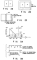
- FIG. 1 illustrates one embodiment of the present invention
- FIGS. 2A and 2B show, in order to clarify the operation of the apparatus, arrangements of the images formed by use of the apparatus
- FIG. 2C illustrates the structure of the charge-coupled device as a solid state imager.
- 100 denotes a body as a housing of the camera, for example, formed as a cylindrical shape.
- a protector 101 made of a transparent material.
- a partition plate 102 is arranged in an axial direction.
- One end portion of the partition plate 102 is integrated with a rear plate 103 formed to be integrated with an inner wall on one side of the body 100.
- a round hole is formed such that a bung 104 is attached therewith.
- the partition plate 102, rear plate 103, and a part of the inner wall of the body 100 form a container section 105.
- the container section 105 is concealed to prevent the permeation of water.
- the side wall of the body 100 forming the container 105 is provided with a lens 111 so as to obtain images on the side of the body.
- the front wall of the body 100 which also forms the container 105 is provided with a lens 112 so as to obtain images in front of the body.
- the light beam supplied from an optical image A passing through the lens 111 for example, is picked up by an image sensing surface of the charge-coupled device 120, which is arranged on the right side, for example.
- the light beam supplied from an optical image B through the lens 112 passes through a prism 113 and turns its passing direction and is picked up by an image sensing surface of the charge-coupled device 120, which is arranged on the left side, for example.
- FIG. 2A schematically illustrates images A and B read as photoelectrically converted images after the images are picked up by the image sensing surfaces of the charge-coupled device 120.
- the image B is laterally inverted (left to right) when the direction in which the light beam passes is turned due to the prism 103.
- the photoelectrically converted signal of the charge-coupled device is output to an amplifier 121 and undergone a noise reduction process in a noise reduction circuit 122.
- the signal undergone the noise reduction process is input to a color separating and signal processing circuit 123 so as to be decoded as a standard video signal.
- the signal processing circuit 123 has a function for dividing the images A and B by outputting each of the image signals A and B so as to be divided to each other.
- the dividing process is executed by a method in which, the output signals are divided in the midst of a horizontal scanning, for example, by use of a switch. If the images A and B are parallelly located in a vertical direction, the signals are divided in the midst of a vertical scanning by use of the switch.
- the image signal of the image A is supplied to a synthesizer 125 through a delay line 124. While, the image signal of the image B is input to an image inverting circuit 126 to be laterally inverted and then supplied to the synthesizer 125.
- the synthesizer 125 synthesizes the image signal of the image B output from the image inverting circuit 126 and the image signal of the image A output from the color separating and signal processing circuit 123, and converts the time-multiplied signal into a video signal to be displayed as one synthesized image.
- the output of the synthesizer 125 is supplied to a monitor 130 through the amplifier 127. In this manner, the images A and B are displayed on the monitor 130 so as not to be inverted, as shown in FIG. 2B.
- the inverting process of the image inverting circuit 126 is executed for inverting the time axis of the horizontal scanning of the image signals by using a memory device. Due to this process of the image circuit 126, the time delay occurs in the signal propagation of the image B. In order to make the image signal for the image A arrive at the same time as the image signal of the image B, the image signal of the image A is delayed by the delay line 124 before the signal is input to the synthesizer 125.
- an optical black portion 140 shown in FIG. 2C is arranged on one end portion of the horizontal scanning in order to prevent the influence of a dark current.
- the charge-coupled device 120 of the present invention is supplied with an image separating black portion 141 for shielding light in the midst of the device.
- the image separating black portion 141 is formed by use of a photolithography or painting method to apply an aluminum layer on a transparent protective film as an insulating layer formed on a sensing section of the charge-coupled device.
- the video camera of this embodiment is intended to obtain both the image A in front of the body and the image B located above or below the body, the above-mentioned lateral image inverting process is replaced with a vertical image inverting process.
- the influence of the image separating black portion 141 on the charge-coupled device 120 is emerged as a black belt-like zone in the central portion of the display when the output of the charge-coupled device 120 is displayed without any processing.
- This influence can be removed from the displayed image by changing the period of time set for reading a signal from the lateral inverting circuit 126 or adjusting the delay time of the delay line 124.
- FIG. 3A presents a sectional view illustrating a specific constitution of the charged-coupled device 120.
- integrated shielding members 151, 152, and 153 are arranged immediately on the optical black portion 140, the image separating black portion 141, and a starting point of the horizontal line, respectively.
- the shielding member 152 is provided to shield the light beams passing through the space between left and right image areas in order to prevent the interference between the light beams supplied from the image areas.
- the shielding members 151, 152, and 153 are also used as a spacer for connecting the prism 113, a protective glass layer 114, and the charge-coupled device 120 to each other.
- FIG. 3B shows a timing chart for comparing a signal S1 generated by the charge-coupled device 120 of the present invention and a signal S2 generated by the conventional charge-coupled device.
- the timing chart clearly shows that, according to the charge-coupled device 120 of the present invention, image signals of two images can be obtained even in accordance with the conventional image reading process.
- the above-mentioned embodiment relates to an example for imaging objects located in two directions.
- the present invention is not limited to the above embodiment.
- FIG. 1 will be described again.
- a through hole 107 is provided in the front of the space 106.
- This hole can be used as a hole in which a lighting device for lighting the front of the body, or a forceps used for a surgical operation or the like is fitted.
- only one through hole 107 is illustrated, but a plurality of holes are provided to the apparatus, in fact.
- the side wall of the body 100 is also provided with a through hole 108 for providing a lighting.
- the video camera apparatus shown in FIG. 1 effectively works as a medical camera. For example, when a stomach is monitored by use of this camera, the images of the portions located in front and on the side of the camera can be simultaneously obtained without turning the camera.
- the color separating and signal processing circuit 123 executes a color signal generating process, then executes a separation of the images.
- the color signal generating process is executed at first so as not to prevent the color synchronization. If the separation of the images were executed at first, the original color of the images could not be precisely reproduced.
- the body is defined as a cylindrical shape. However, the body may be formed as an oval, or triangle or square pole.
- the charge-coupled device 120 is described as a color charge-coupled device having color filters, but may be a monochrome charge-coupled device, of course.
- the body may be also formed with a transparent material so as to be integrated with the lenses.
- the body 100 when the body 100 contains the noise reduction circuit 122, color separating and signal processing circuit 123, image inverting circuit 126, delay line 124, synthesizer 125, and amplifier 127, the body 100 is formed as a fixing structure to be sufficiently waterproofed and to resist the shaking. In the embodiment, these elements are integrated contained in the body 100, but may be formed out of the body 100 at a distance. Similarly, the outputs from the image inverting circuit 126 and the delay line 124 are synthesized by the synthesizer 125, but may be input to different monitors respectively.
- FIG. 4A shows another embodiment of the present invention.
- the apparatus of this embodiment is provided with first, second, and third lenses 201, 202, and 203.
- the first lens 201 gets a ray from the object and an image passes through a protective glass layer 211 and is picked up by an image sensing surface 301 located in a midst of a charge-coupled device 300.
- the second lens 202 gets a light beam supplied from the object located on the left side and the light beam supplied from the image passes through a prism 212 and is picked up by an image sensing surface 302 located in the left side of a charge-coupled device 300.
- the third lens 203 also gets a light beam from the object and an image passes through a prism 213 and is picked up by an image sensing surface 303 located in the right side of a charge-coupled device 300.
- reference numbers 351, 352, 353, and 354 denote shielding members for optically separating the image sensing surfaces from each other.
- image separation black portions 361, 362, 363 and 364 are formed in the charge-coupled device 300.
- the video camera apparatus can be formed as a wide-angle camera which has an imaging area of 270° as shown in FIG. 4B and will not cause so large optical distortion. According to this camera, front, left, and right images can be displayed on the monitor as shown in FIG. 4C.
- This video camera apparatus effectively works as a monitoring camera. If this camera is equipped in a car, the driver can easily monitor the front, left, and right directions. The camera can be set up in rear of a car to effectively monitor the backward, left and right.
- the present invention is not limited to the above-mentioned embodiments, but can be used as a three-dimensional video camera.
- FIG. 5 presents an example of a three-dimensional video camera.
- a body 500 is provided with left and right imaging lenses 5L and 5R each having a convergence angle.
- the light beam supplied from optical images AL and AR pass through the lenses 5L and 5R and arrive at the left and right portions of the image sensing surface of the charge-coupled device 520 through prisms (or reflecting mirrors) 51L and 51R.
- Image signals generated by the charge-coupled device 520 are input into an image dividing circuit 522 through an amplifier 521 and divided into left and right image signals.
- the user can obtain a three-dimensional image on the basis of the left and right images by a method using a peephole or glasses.
- FIG. 6 shows still another embodiment of the present invention.
- charge-coupled devices 120R and 120L are coupled back to back with an adhesive and arranged to hold a central axis of a body 600 there-between.
- Lenses 111R and 111L are arranged oppositely to the rear portions of image sensing areas of the charge-coupled devices 120R and 120L.
- the lenses 111R and 111L are fixed to the side walls of the body 600.
- the front portions of the image sensing areas of the charge-coupled devices 120R and 120L are provided with prisms 113R and 113L respectively so as to be integratedly formed therewith.
- the prisms 113R and 113L respectively receive the optical images passing through lenses 112R and 112L.
- the lenses 112R and 112L is set in and fixed in holes in a front wall of the body 600.
- the front edges and the side edges of the charge-coupled devices 120R and 120L are supported by a supporting member 611 formed in the body 600, and the rear edges of the charge-coupled devices 120R and 120L are supported by a fixing member 621.
- the fixing member 621 has guiding portions for guiding wirings connected to the charge-coupled devices 120R and 120L.
- the images of the front and left and right sides of the object can be obtained, and thus the imaging area can be enhanced.
- How to process and display the imaging signals is determined by a video signal processing circuit for dividing the imaging signals.
- the supporting member 611 is arranged in the body 600.
- the supporting member 611 can be also formed as the rotation axis of a body 600 arranged in the center of the body 600.
- the charge-coupled devices 120R and 120L and prisms 113R and 113L are integrated and rotatably arranged in the body.
- the integrated element is called as a imaging unit.
- lenses having a magnification different from the lenses 111R and 111L may be provided on the circumference of a circle of the section of the body, on which the lenses 111R and 111L are arranged. By providing the lenses with different magnifications in this manner, the user can select a most suitable lens to obtain an image of the object in accordance with the distance between the body and object.
- a small video camera apparatus capable of imaging an object from various angles, and effectively obtaining three-dimensional image information, can be obtained.
- FIG. 7 shows another embodiment of the present invention.
- the protector 101 has a plurality of converting lenses 115, 116, 117, ⁇ (116, 117 are not shown) on the circumference, and the protector 101 can rotate on the body 100, then one of converting lenses is selectively corresponded to the lens 111. According to this embodiment, different magnification images are obtained by switching the converting lenses. Since another portions are same with the embodiment shown FIG. 1, the explanation of those portions is abridged.
Abstract
Description
- This invention relates to a video camera apparatus useful as a monitoring camera, three dimensional camera, endoscopic camera, and so on.
- A system comprising a plurality of video cameras is known which is used as a factory monitoring camera system. In this system, the outputs from the plurality of cameras are input to an image synthesizer, and the synthesized image output from the image synthesizer is displayed on the monitor. Known as electronic endoscope cameras are a both front-view type camera and a side-view type camera which type should be used depends on photographing conditions or requirements.
- In the conventional monitoring system, a plurality of images photographed by the cameras are simultaneously displayed on one monitor by executing the image synthesizing, or different types of cameras are used separately in accordance with the photographing conditions. Therefore, the conventional monitoring system has to comprise a plurality of cameras in order to simultaneously obtain a plurality of images. Similarly, when images in a plurality of directions are simultaneously required, the conventional electronic endoscope camera cannot provide the desired images.
- The object of the present invention is to provide a small video camera apparatus capable of imaging an object from various angles.
- Another object of the present invention is to provide a video camera apparatus useful as a monitor for obtaining image information or an apparatus for obtaining three-dimensional image information.
- In order to attain these objects, a video camera apparatus according to the invention comprises: a body; first and second optical systems arranged at different positions on the body; a charge-coupled device provided in the body and having image sensing surfaces separated by a black portion, for generating an image signal from light beams supplied from the first and second optical systems, respectively; and dividing means for dividing the image signal representing a first image and a second image signal corresponding to the image sensing surfaces.
- The video camera apparatus can generate image information from a plurality of angles by use of the small charge-coupled device formed in the body.
- This invention can be more fully understood from the following detailed description when taken in conjunction with the accompanying drawings, in which:
- FIG. 1 shows a schematic drawing illustrating one embodiment of the video camera apparatus of the present invention;
- FIGS. 2A and 2B show schematic drawings illustrating the operation of the video camera apparatus shown in FIG. 1, and FIG. 2C shows a schematic drawing of the charge-coupled device formed in the video camera apparatus of FIG. 1;
- FIG. 3A shows a schematic drawing illustrating a charge-coupled device section of the video camera apparatus of the present invention, and FIG. 3B shows a timing chart of the signals read from the charge-coupled device;
- FIG. 4A shows a schematic drawing illustrating another embodiment of the video camera apparatus, FIG. 4B shows a drawing showing an imaging area of the video camera apparatus, and FIG. 4C shows a drawing illustrating an image formed by the video camera apparatus;
- FIG. 5 shows a schematic drawing illustrating still another embodiment of the video camera apparatus of the present invention;
- FIG. 6 shows a schematic drawing illustrating further another embodiment of the video camera apparatus of the present invention; and
- FIG. 7 shows a schematic drawing illustrating another embodiment of the video camera apparatus.
- The embodiments of the present invention will be described below with reference to the drawings.
- FIG. 1 illustrates one embodiment of the present invention, FIGS. 2A and 2B show, in order to clarify the operation of the apparatus, arrangements of the images formed by use of the apparatus, and FIG. 2C illustrates the structure of the charge-coupled device as a solid state imager.
- In FIG. 1, 100 denotes a body as a housing of the camera, for example, formed as a cylindrical shape. One end portion of the body is covered with a
protector 101 made of a transparent material. In thebody 100, apartition plate 102 is arranged in an axial direction. One end portion of thepartition plate 102 is integrated with arear plate 103 formed to be integrated with an inner wall on one side of thebody 100. In therear plate 103, a round hole is formed such that abung 104 is attached therewith. Thepartition plate 102,rear plate 103, and a part of the inner wall of thebody 100 form acontainer section 105. Thecontainer section 105 is concealed to prevent the permeation of water. - The side wall of the
body 100 forming thecontainer 105 is provided with alens 111 so as to obtain images on the side of the body. The front wall of thebody 100 which also forms thecontainer 105 is provided with alens 112 so as to obtain images in front of the body. The light beam supplied from an optical image A passing through thelens 111, for example, is picked up by an image sensing surface of the charge-coupleddevice 120, which is arranged on the right side, for example. Similarly, the light beam supplied from an optical image B through thelens 112 passes through aprism 113 and turns its passing direction and is picked up by an image sensing surface of the charge-coupleddevice 120, which is arranged on the left side, for example. - FIG. 2A schematically illustrates images A and B read as photoelectrically converted images after the images are picked up by the image sensing surfaces of the charge-coupled
device 120. The image B is laterally inverted (left to right) when the direction in which the light beam passes is turned due to theprism 103. - The photoelectrically converted signal of the charge-coupled device is output to an
amplifier 121 and undergone a noise reduction process in anoise reduction circuit 122. The signal undergone the noise reduction process is input to a color separating andsignal processing circuit 123 so as to be decoded as a standard video signal. Thesignal processing circuit 123 has a function for dividing the images A and B by outputting each of the image signals A and B so as to be divided to each other. The dividing process is executed by a method in which, the output signals are divided in the midst of a horizontal scanning, for example, by use of a switch. If the images A and B are parallelly located in a vertical direction, the signals are divided in the midst of a vertical scanning by use of the switch. - The image signal of the image A is supplied to a
synthesizer 125 through adelay line 124. While, the image signal of the image B is input to an image invertingcircuit 126 to be laterally inverted and then supplied to thesynthesizer 125. Thesynthesizer 125 synthesizes the image signal of the image B output from theimage inverting circuit 126 and the image signal of the image A output from the color separating andsignal processing circuit 123, and converts the time-multiplied signal into a video signal to be displayed as one synthesized image. The output of thesynthesizer 125 is supplied to amonitor 130 through theamplifier 127. In this manner, the images A and B are displayed on themonitor 130 so as not to be inverted, as shown in FIG. 2B. The inverting process of theimage inverting circuit 126 is executed for inverting the time axis of the horizontal scanning of the image signals by using a memory device. Due to this process of theimage circuit 126, the time delay occurs in the signal propagation of the image B. In order to make the image signal for the image A arrive at the same time as the image signal of the image B, the image signal of the image A is delayed by thedelay line 124 before the signal is input to thesynthesizer 125. - In a conventional charge-coupled device, an optical
black portion 140 shown in FIG. 2C is arranged on one end portion of the horizontal scanning in order to prevent the influence of a dark current. In addition to the optical black portion, the charge-coupleddevice 120 of the present invention is supplied with an image separatingblack portion 141 for shielding light in the midst of the device. The image separatingblack portion 141 is formed by use of a photolithography or painting method to apply an aluminum layer on a transparent protective film as an insulating layer formed on a sensing section of the charge-coupled device. - If the video camera of this embodiment is intended to obtain both the image A in front of the body and the image B located above or below the body, the above-mentioned lateral image inverting process is replaced with a vertical image inverting process.
- In addition, the influence of the image separating
black portion 141 on the charge-coupleddevice 120 is emerged as a black belt-like zone in the central portion of the display when the output of the charge-coupleddevice 120 is displayed without any processing. This influence can be removed from the displayed image by changing the period of time set for reading a signal from thelateral inverting circuit 126 or adjusting the delay time of thedelay line 124. - FIG. 3A presents a sectional view illustrating a specific constitution of the charged-coupled
device 120. On the charge-coupled device, integrated shieldingmembers black portion 140, the image separatingblack portion 141, and a starting point of the horizontal line, respectively. In particular, the shieldingmember 152 is provided to shield the light beams passing through the space between left and right image areas in order to prevent the interference between the light beams supplied from the image areas. The shieldingmembers prism 113, aprotective glass layer 114, and the charge-coupleddevice 120 to each other. - FIG. 3B shows a timing chart for comparing a signal S1 generated by the charge-coupled
device 120 of the present invention and a signal S2 generated by the conventional charge-coupled device. The timing chart clearly shows that, according to the charge-coupleddevice 120 of the present invention, image signals of two images can be obtained even in accordance with the conventional image reading process. - The above-mentioned embodiment relates to an example for imaging objects located in two directions. The present invention, however, is not limited to the above embodiment.
- FIG. 1 will be described again.
- In the
body 100 of FIG. 1, there is a space on the opposite side of thecontainer section 105 with regard to thepartition plate 102, i.e., under thecontainer section 105. In the front of thespace 106, a throughhole 107 is provided. This hole can be used as a hole in which a lighting device for lighting the front of the body, or a forceps used for a surgical operation or the like is fitted. In FIG. 1, only one throughhole 107 is illustrated, but a plurality of holes are provided to the apparatus, in fact. Similarly, the side wall of thebody 100 is also provided with a throughhole 108 for providing a lighting. - The video camera apparatus shown in FIG. 1 effectively works as a medical camera. For example, when a stomach is monitored by use of this camera, the images of the portions located in front and on the side of the camera can be simultaneously obtained without turning the camera.
- In the signal processing of the video camera of the present invention, the color separating and
signal processing circuit 123 executes a color signal generating process, then executes a separation of the images. In the signal processing, the color signal generating process is executed at first so as not to prevent the color synchronization. If the separation of the images were executed at first, the original color of the images could not be precisely reproduced. - In FIG. 1, the body is defined as a cylindrical shape. However, the body may be formed as an oval, or triangle or square pole. The charge-coupled
device 120 is described as a color charge-coupled device having color filters, but may be a monochrome charge-coupled device, of course. The body may be also formed with a transparent material so as to be integrated with the lenses. - Further, when the
body 100 contains thenoise reduction circuit 122, color separating andsignal processing circuit 123,image inverting circuit 126,delay line 124,synthesizer 125, andamplifier 127, thebody 100 is formed as a fixing structure to be sufficiently waterproofed and to resist the shaking. In the embodiment, these elements are integrated contained in thebody 100, but may be formed out of thebody 100 at a distance. Similarly, the outputs from theimage inverting circuit 126 and thedelay line 124 are synthesized by thesynthesizer 125, but may be input to different monitors respectively. - FIG. 4A shows another embodiment of the present invention.
- As shown in FIG. 4A, the apparatus of this embodiment is provided with first, second, and
third lenses first lens 201 gets a ray from the object and an image passes through aprotective glass layer 211 and is picked up by animage sensing surface 301 located in a midst of a charge-coupleddevice 300. Similarly, thesecond lens 202 gets a light beam supplied from the object located on the left side and the light beam supplied from the image passes through aprism 212 and is picked up by animage sensing surface 302 located in the left side of a charge-coupleddevice 300. Thethird lens 203 also gets a light beam from the object and an image passes through aprism 213 and is picked up by animage sensing surface 303 located in the right side of a charge-coupleddevice 300. In FIG. 4A,reference numbers members black portions device 300. - By virtue of this structure, the video camera apparatus can be formed as a wide-angle camera which has an imaging area of 270° as shown in FIG. 4B and will not cause so large optical distortion. According to this camera, front, left, and right images can be displayed on the monitor as shown in FIG. 4C.
- This video camera apparatus effectively works as a monitoring camera. If this camera is equipped in a car, the driver can easily monitor the front, left, and right directions. The camera can be set up in rear of a car to effectively monitor the backward, left and right.
- The present invention is not limited to the above-mentioned embodiments, but can be used as a three-dimensional video camera.
- FIG. 5 presents an example of a three-dimensional video camera.
- A
body 500 is provided with left andright imaging lenses lenses device 520 through prisms (or reflecting mirrors) 51L and 51R. Image signals generated by the charge-coupleddevice 520 are input into animage dividing circuit 522 through anamplifier 521 and divided into left and right image signals. The user can obtain a three-dimensional image on the basis of the left and right images by a method using a peephole or glasses. - FIG. 6 shows still another embodiment of the present invention.
- In this embodiment, charge-coupled
devices body 600 there-between. Lenses 111R and 111L are arranged oppositely to the rear portions of image sensing areas of the charge-coupleddevices body 600. The front portions of the image sensing areas of the charge-coupleddevices prisms prisms lenses lenses body 600. - The front edges and the side edges of the charge-coupled
devices body 600, and the rear edges of the charge-coupleddevices devices - According to the video camera apparatus of this embodiment, the images of the front and left and right sides of the object can be obtained, and thus the imaging area can be enhanced. How to process and display the imaging signals is determined by a video signal processing circuit for dividing the imaging signals.
- In the above embodiment, the supporting member 611 is arranged in the
body 600. The supporting member 611, however, can be also formed as the rotation axis of abody 600 arranged in the center of thebody 600. In this case, the charge-coupleddevices prisms - As described above, according to the present invention, a small video camera apparatus capable of imaging an object from various angles, and effectively obtaining three-dimensional image information, can be obtained.
- FIG. 7 shows another embodiment of the present invention.
- In this embodiment, the
protector 101 has a plurality of convertinglenses 115, 116, 117, ··· (116, 117 are not shown) on the circumference, and theprotector 101 can rotate on thebody 100, then one of converting lenses is selectively corresponded to thelens 111. According to this embodiment, different magnification images are obtained by switching the converting lenses. Since another portions are same with the embodiment shown FIG. 1, the explanation of those portions is abridged.
Claims (8)
- A video camera apparatus comprising:
a body (100);
first and second optical systems (111, 112, 113, 202, 203) arranged at different positions on the body (100);
a charge-coupled device (120, 300) provided in the body and having image sensing surfaces separated by a black portion, for generating an image signal from light beams supplied from the first and second optical systems, respectively; and
dividing means (123) for dividing the image signal representing a first image and a second image signal corresponding to said image sensing surfaces. - A video camera apparatus according to claim 1, characterized in that at least one of the first and second optical systems is integrated with one of the image sensing surfaces.
- A video camera apparatus according to claim 1, characterized in that the image sensing surfaces of the charge-coupled device are in parallel with an axis of the body.
- A video camera apparatus according to claim 1, characterized in that the second optical system (112, 113) guides a light beam supplied from an optical image to one of the image sensing surfaces through a reflection member, and the first optical system (111) guides a light beam supplied from an optical image directly to another one of the image sensing surface.
- A video camera apparatus according to claim 1, characterized in that the first and second optical systems (202, 203) respectively guide light beams supplied from optical images to the image sensing surfaces of the charge-coupled device (300) through reflection member (212, 213).
- A video camera apparatus according to claim 1, characterized by further comprising a lateral image inverting circuit (126) for inverting a time-axis of a horizontal scanning of one of the signals divided by the image signal dividing means (123).
- A video camera apparatus according to claim 6, characterized by further comprising converting means (125) for time-multiplying a second image signal output from the lateral image inverting circuit (126) and said one of the signals divided by the image signal dividing means so as to convert the image signals into one video signal.
- A video camera apparatus comprising:
a charge-coupled device (300) formed in the body;
first optical system (202) for guiding a light beam supplied from a first optical image to a first image sensing surface of the charge-coupled device through a first reflection member (212);
second optical system (203) for guiding a light beam supplied from a second optical image to a second image sensing surface of the charge-coupled device through a second reflection member (213); and
third optical system (201) for guiding a light beam supplied from a third optical image directly to a third image sensing surface of the charge-coupled device.
Applications Claiming Priority (2)
| Application Number | Priority Date | Filing Date | Title |
|---|---|---|---|
| JP260546/94 | 1994-10-25 | ||
| JP26054694 | 1994-10-25 |
Publications (2)
| Publication Number | Publication Date |
|---|---|
| EP0710039A2 true EP0710039A2 (en) | 1996-05-01 |
| EP0710039A3 EP0710039A3 (en) | 1996-11-13 |
Family
ID=17349465
Family Applications (1)
| Application Number | Title | Priority Date | Filing Date |
|---|---|---|---|
| EP95116819A Withdrawn EP0710039A3 (en) | 1994-10-25 | 1995-10-25 | Video camera apparatus |
Country Status (3)
| Country | Link |
|---|---|
| US (1) | US5940126A (en) |
| EP (1) | EP0710039A3 (en) |
| KR (1) | KR100220524B1 (en) |
Cited By (19)
| Publication number | Priority date | Publication date | Assignee | Title |
|---|---|---|---|---|
| EP1079613A2 (en) * | 1999-08-20 | 2001-02-28 | Minolta Co., Ltd. | Image input apparatus |
| EP1146733A1 (en) * | 2000-04-10 | 2001-10-17 | Mitsubishi Denki Kabushiki Kaisha | Image pickup device and portable telephone including the same |
| WO2001082633A1 (en) * | 2000-04-20 | 2001-11-01 | Walter Moser | Recording of dynamic sequences with three dimensional representation and photogrammetry |
| EP1173009A1 (en) * | 2000-06-22 | 2002-01-16 | Mitsubishi Denki Kabushiki Kaisha | Image pick-up apparatus and portable telephone utilizing the same |
| EP1067802A3 (en) * | 1999-06-30 | 2002-11-27 | Canon Kabushiki Kaisha | Colour image pickup apparatus |
| EP1067779A3 (en) * | 1999-06-30 | 2002-11-27 | Canon Kabushiki Kaisha | Image pickup apparatus |
| WO2003098920A1 (en) * | 2002-05-16 | 2003-11-27 | Koninklijke Philips Electronics N.V. | Image sensor device |
| EP1289316A3 (en) * | 2001-08-23 | 2004-11-17 | Valeo Schalter und Sensoren GmbH | Environment monitoring system |
| US7235831B2 (en) | 1999-02-25 | 2007-06-26 | Canon Kabushiki Kaisha | Light-receiving element and photoelectric conversion device |
| US7474349B2 (en) | 2002-12-26 | 2009-01-06 | Canon Kabushiki Kaisha | Image-taking apparatus |
| EP2139224A1 (en) * | 2008-06-23 | 2009-12-30 | SMR PATENTS S.à.r.l. | Imaging system, sensor unit with an imaging system and vehicle mirror comprising an imaging system |
| WO2012056453A2 (en) | 2010-10-28 | 2012-05-03 | Peermedical Ltd. | Optical systems for multi-sensor endoscopes |
| WO2014130547A1 (en) | 2013-02-19 | 2014-08-28 | Integrated Medical Systems International, Inc. | Endoscope with pupil expander |
| CN104799803A (en) * | 2015-05-14 | 2015-07-29 | 珠海视新医用科技有限公司 | Dual-lens distal end part structure for endoscope |
| CN105636499A (en) * | 2013-07-01 | 2016-06-01 | 恩多巧爱思股份有限公司 | Circuit board assembly of a multiple viewing elements endoscope |
| DE102014224903A1 (en) * | 2014-12-04 | 2016-06-09 | Conti Temic Microelectronic Gmbh | Optical environment sensor for vehicles |
| WO2017121609A1 (en) * | 2016-01-13 | 2017-07-20 | Fraunhofer-Gesellschaft zur Förderung der angewandten Forschung e.V. | Multi-aperture imaging device, imaging system and method for detecting an object region |
| EP3482673A1 (en) * | 2013-05-06 | 2019-05-15 | EndoChoice, Inc. | Image capture assembly for use in a multi-viewing elements endoscope |
| EP3747343A1 (en) * | 2010-12-09 | 2020-12-09 | EndoChoice, Inc. | Flexible electronic circuit board multi-camera endoscope |
Families Citing this family (163)
| Publication number | Priority date | Publication date | Assignee | Title |
|---|---|---|---|---|
| US6795120B2 (en) * | 1996-05-17 | 2004-09-21 | Sony Corporation | Solid-state imaging apparatus and camera using the same |
| JP2001500029A (en) * | 1996-08-12 | 2001-01-09 | エムゲーベー エンドスコピッシェ ゲレーテ ゲゼルシャフト ミット ベシュレンクテル ハフツング ベルリン | Rigid (endoscope) endoscope with irradiation system |
| JPH10257396A (en) * | 1997-03-06 | 1998-09-25 | Toshiba Corp | Area separating type solid-state image-pickup device |
| US6750848B1 (en) | 1998-11-09 | 2004-06-15 | Timothy R. Pryor | More useful man machine interfaces and applications |
| US20020036617A1 (en) | 1998-08-21 | 2002-03-28 | Timothy R. Pryor | Novel man machine interfaces and applications |
| US6778211B1 (en) * | 1999-04-08 | 2004-08-17 | Ipix Corp. | Method and apparatus for providing virtual processing effects for wide-angle video images |
| AU4336400A (en) * | 1999-04-08 | 2000-10-23 | Internet Pictures Corporation | Method and apparatus for providing virtual processing effects for wide-angle video images |
| JP2002542729A (en) * | 1999-04-15 | 2002-12-10 | コーニンクレッカ フィリップス エレクトロニクス エヌ ヴィ | Camera with auxiliary camera |
| US7015950B1 (en) | 1999-05-11 | 2006-03-21 | Pryor Timothy R | Picture taking method and apparatus |
| US6766036B1 (en) * | 1999-07-08 | 2004-07-20 | Timothy R. Pryor | Camera based man machine interfaces |
| JP2001036776A (en) * | 1999-07-15 | 2001-02-09 | Mitsubishi Electric Corp | Image pickup device |
| US6767321B2 (en) * | 1999-10-04 | 2004-07-27 | Robert Czarnek | Stereo laparoscope with discrete working distance |
| JP2001197485A (en) * | 2000-01-11 | 2001-07-19 | Asahi Optical Co Ltd | Electronic endoscope system and electronic endoscope signal switching device |
| JP2001275964A (en) * | 2000-03-29 | 2001-10-09 | Matsushita Electric Ind Co Ltd | Video scope |
| IL135571A0 (en) * | 2000-04-10 | 2001-05-20 | Doron Adler | Minimal invasive surgery imaging system |
| US6692430B2 (en) * | 2000-04-10 | 2004-02-17 | C2Cure Inc. | Intra vascular imaging apparatus |
| AU2001261284A1 (en) | 2000-05-09 | 2001-11-20 | Jon Oshima | Multiplexed motion picture camera |
| US6992699B1 (en) * | 2000-08-02 | 2006-01-31 | Telefonaktiebolaget Lm Ericsson (Publ) | Camera device with selectable image paths |
| US20060250514A1 (en) * | 2001-01-09 | 2006-11-09 | Mitsubishi Denki Kabushiki Kaisha | Imaging apparatus |
| US7553276B2 (en) * | 2001-01-16 | 2009-06-30 | Given Imaging Ltd. | Method and device for imaging body lumens |
| JP4486762B2 (en) * | 2001-03-08 | 2010-06-23 | 富士フイルム株式会社 | Image photographing method and apparatus |
| US7061532B2 (en) * | 2001-03-27 | 2006-06-13 | Hewlett-Packard Development Company, L.P. | Single sensor chip digital stereo camera |
| US6869397B2 (en) * | 2001-06-01 | 2005-03-22 | The Board Of Trustees Of The Leland Stanford Junior University | Non-tethered macro-to-micro endoscope |
| DE60228266D1 (en) | 2001-06-18 | 2008-09-25 | Given Imaging Ltd | SWITCHABLE IN VIVO CAPSULE WITH A RIGID AND FLEXIBLE SECTION CIRCUIT BOARD |
| JP4663230B2 (en) * | 2001-06-28 | 2011-04-06 | ギブン イメージング リミテッド | In vivo imaging device having a small cross-sectional area and method for constructing the same |
| US6951536B2 (en) * | 2001-07-30 | 2005-10-04 | Olympus Corporation | Capsule-type medical device and medical system |
| JP4393866B2 (en) * | 2001-08-02 | 2010-01-06 | ギブン イメージング リミテッド | In vivo imaging capsule |
| IL162420A0 (en) * | 2001-12-11 | 2005-11-20 | C2Cure Inc | Apparatus, method and system for intravascular ph otographic imaging |
| US7184086B2 (en) * | 2002-02-25 | 2007-02-27 | Konica Corporation | Camera having flexible display |
| US7591780B2 (en) * | 2002-03-18 | 2009-09-22 | Sterling Lc | Miniaturized imaging device with integrated circuit connector system |
| US8614768B2 (en) | 2002-03-18 | 2013-12-24 | Raytheon Company | Miniaturized imaging device including GRIN lens optically coupled to SSID |
| US20060146172A1 (en) * | 2002-03-18 | 2006-07-06 | Jacobsen Stephen C | Miniaturized utility device having integrated optical capabilities |
| US7787939B2 (en) | 2002-03-18 | 2010-08-31 | Sterling Lc | Miniaturized imaging device including utility aperture and SSID |
| DE10392670B4 (en) * | 2002-05-16 | 2012-10-11 | C2Cure Inc. | Miniature camera head |
| US20040001145A1 (en) * | 2002-06-27 | 2004-01-01 | Abbate Jeffrey A. | Method and apparatus for multifield image generation and processing |
| US6908307B2 (en) * | 2003-02-03 | 2005-06-21 | Schick Technologies | Dental camera utilizing multiple lenses |
| WO2004096008A2 (en) * | 2003-05-01 | 2004-11-11 | Given Imaging Ltd. | Panoramic field of view imaging device |
| JP4533695B2 (en) * | 2003-09-23 | 2010-09-01 | オリンパス株式会社 | Treatment endoscope |
| US8639314B2 (en) * | 2003-12-24 | 2014-01-28 | Given Imaging Ltd. | Device, system and method for in-vivo imaging of a body lumen |
| WO2005060348A2 (en) * | 2003-12-24 | 2005-07-07 | Given Imaging Ltd. | Device, system and method for in-vivo imaging of a body lumen |
| WO2005082226A1 (en) * | 2004-02-27 | 2005-09-09 | Olympus Corporation | Endoscope |
| US20060015013A1 (en) * | 2004-06-30 | 2006-01-19 | Zvika Gilad | Device and method for in vivo illumination |
| US7336833B2 (en) * | 2004-06-30 | 2008-02-26 | Given Imaging, Ltd. | Device, system, and method for reducing image data captured in-vivo |
| WO2006004083A1 (en) * | 2004-07-02 | 2006-01-12 | Osaka University | Endoscope attachment and endoscope |
| US7300397B2 (en) * | 2004-07-29 | 2007-11-27 | C2C Cure, Inc. | Endoscope electronics assembly |
| US8585584B2 (en) | 2004-10-11 | 2013-11-19 | Nitesh Ratnakar | Dual view endoscope |
| US11653816B2 (en) * | 2004-10-11 | 2023-05-23 | Nitesh Ratnakar | Next generation endoscope |
| US7621869B2 (en) * | 2005-05-06 | 2009-11-24 | Nitesh Ratnakar | Next generation colonoscope |
| IL166595A0 (en) * | 2005-01-31 | 2006-01-15 | Uri Neta | Image acquisition system |
| US20060217593A1 (en) * | 2005-03-24 | 2006-09-28 | Zvika Gilad | Device, system and method of panoramic multiple field of view imaging |
| US20060221218A1 (en) * | 2005-04-05 | 2006-10-05 | Doron Adler | Image sensor with improved color filter |
| US20070203396A1 (en) * | 2006-02-28 | 2007-08-30 | Mccutcheon John G | Endoscopic Tool |
| WO2007113801A2 (en) * | 2006-03-30 | 2007-10-11 | Given Imaging Ltd. | In-vivo sensing device and method for communicating between imagers and processor thereof |
| CN101433077B (en) * | 2006-05-05 | 2011-03-23 | 诺基亚公司 | Optical image recording device with small height and high resolution |
| JP4574596B2 (en) * | 2006-07-06 | 2010-11-04 | 富士フイルム株式会社 | Capsule endoscope |
| US7889435B2 (en) * | 2006-10-17 | 2011-02-15 | Samsung Electronics Co., Ltd. | Imaging device having a dual lens optical system |
| KR101278239B1 (en) * | 2006-10-17 | 2013-06-24 | 삼성전자주식회사 | Dual lens optical system and Dual lens camera comprising the same |
| US8662762B2 (en) * | 2006-10-17 | 2014-03-04 | Samsung Electronics Co., Ltd. | Compact lens optical system and digital camera module including the same |
| US7933071B2 (en) * | 2006-10-17 | 2011-04-26 | Samsung Electronics Co., Ltd. | Dual lens optical system and digital camera module including the same |
| US8814779B2 (en) | 2006-12-21 | 2014-08-26 | Intuitive Surgical Operations, Inc. | Stereoscopic endoscope |
| US8556807B2 (en) * | 2006-12-21 | 2013-10-15 | Intuitive Surgical Operations, Inc. | Hermetically sealed distal sensor endoscope |
| DE102008018931A1 (en) | 2007-04-17 | 2008-11-13 | Gyrus ACMI, Inc., Southborough | Light source power based on a predetermined detected condition |
| US7835074B2 (en) | 2007-06-05 | 2010-11-16 | Sterling Lc | Mini-scope for multi-directional imaging |
| US20090046171A1 (en) * | 2007-08-16 | 2009-02-19 | C2Cure, Inc. | Non-linear color correction |
| EP2033571B1 (en) | 2007-09-05 | 2017-02-08 | Vision-Sciences Inc. | Compact endoscope tip and method for assemblying the same |
| US20090102939A1 (en) * | 2007-10-18 | 2009-04-23 | Narendra Ahuja | Apparatus and method for simultaneously acquiring multiple images with a given camera |
| US7969659B2 (en) | 2008-01-11 | 2011-06-28 | Sterling Lc | Grin lens microscope system |
| WO2009155432A2 (en) * | 2008-06-18 | 2009-12-23 | Sterling Lc | Miniaturized imaging device multiple grin lenses optically coupled to multiple ssids |
| JP5596027B2 (en) | 2008-06-18 | 2014-09-24 | レイセオン カンパニー | catheter |
| US9820719B2 (en) | 2008-06-19 | 2017-11-21 | Cogentix Medical, Inc. | Method and system for intrabody imaging |
| US8486735B2 (en) | 2008-07-30 | 2013-07-16 | Raytheon Company | Method and device for incremental wavelength variation to analyze tissue |
| JP2010051538A (en) * | 2008-08-28 | 2010-03-11 | Panasonic Corp | Imaging apparatus |
| WO2010047463A1 (en) * | 2008-10-24 | 2010-04-29 | Meerecompany | Laparoscope and setting method thereof |
| WO2010053916A2 (en) | 2008-11-04 | 2010-05-14 | Sterling Lc | Method and device for wavelength shifted imaging |
| US9795442B2 (en) | 2008-11-11 | 2017-10-24 | Shifamed Holdings, Llc | Ablation catheters |
| JP5225038B2 (en) * | 2008-11-19 | 2013-07-03 | Hoya株式会社 | Optical scanning endoscope, optical scanning endoscope processor, and optical scanning endoscope apparatus |
| US11864734B2 (en) | 2009-06-18 | 2024-01-09 | Endochoice, Inc. | Multi-camera endoscope |
| US9101287B2 (en) * | 2011-03-07 | 2015-08-11 | Endochoice Innovation Center Ltd. | Multi camera endoscope assembly having multiple working channels |
| US9642513B2 (en) | 2009-06-18 | 2017-05-09 | Endochoice Inc. | Compact multi-viewing element endoscope system |
| US9492063B2 (en) | 2009-06-18 | 2016-11-15 | Endochoice Innovation Center Ltd. | Multi-viewing element endoscope |
| US11547275B2 (en) | 2009-06-18 | 2023-01-10 | Endochoice, Inc. | Compact multi-viewing element endoscope system |
| US11278190B2 (en) | 2009-06-18 | 2022-03-22 | Endochoice, Inc. | Multi-viewing element endoscope |
| US9474440B2 (en) | 2009-06-18 | 2016-10-25 | Endochoice, Inc. | Endoscope tip position visual indicator and heat management system |
| US10524645B2 (en) | 2009-06-18 | 2020-01-07 | Endochoice, Inc. | Method and system for eliminating image motion blur in a multiple viewing elements endoscope |
| US9706903B2 (en) | 2009-06-18 | 2017-07-18 | Endochoice, Inc. | Multiple viewing elements endoscope system with modular imaging units |
| US9402533B2 (en) | 2011-03-07 | 2016-08-02 | Endochoice Innovation Center Ltd. | Endoscope circuit board assembly |
| US9101268B2 (en) | 2009-06-18 | 2015-08-11 | Endochoice Innovation Center Ltd. | Multi-camera endoscope |
| WO2010146587A1 (en) | 2009-06-18 | 2010-12-23 | Peer Medical Ltd. | Multi-camera endoscope |
| US9872609B2 (en) * | 2009-06-18 | 2018-01-23 | Endochoice Innovation Center Ltd. | Multi-camera endoscope |
| US10130246B2 (en) | 2009-06-18 | 2018-11-20 | Endochoice, Inc. | Systems and methods for regulating temperature and illumination intensity at the distal tip of an endoscope |
| US10165929B2 (en) | 2009-06-18 | 2019-01-01 | Endochoice, Inc. | Compact multi-viewing element endoscope system |
| US9901244B2 (en) | 2009-06-18 | 2018-02-27 | Endochoice, Inc. | Circuit board assembly of a multiple viewing elements endoscope |
| WO2012077116A1 (en) | 2010-12-09 | 2012-06-14 | Peermedical Ltd. | Flexible electronic circuit board for a multi-camera endoscope |
| US8926502B2 (en) | 2011-03-07 | 2015-01-06 | Endochoice, Inc. | Multi camera endoscope having a side service channel |
| US9713417B2 (en) | 2009-06-18 | 2017-07-25 | Endochoice, Inc. | Image capture assembly for use in a multi-viewing elements endoscope |
| US8512232B2 (en) * | 2009-09-08 | 2013-08-20 | Gyrus Acmi, Inc. | Endoscopic illumination system, assembly and methods for staged illumination of different target areas |
| WO2011041730A2 (en) | 2009-10-01 | 2011-04-07 | Jacobsen Stephen C | Light diffusion apparatus |
| US9144664B2 (en) | 2009-10-01 | 2015-09-29 | Sarcos Lc | Method and apparatus for manipulating movement of a micro-catheter |
| US9661996B2 (en) | 2009-10-01 | 2017-05-30 | Sarcos Lc | Needle delivered imaging device |
| US8828028B2 (en) | 2009-11-03 | 2014-09-09 | Raytheon Company | Suture device and method for closing a planar opening |
| US8764632B2 (en) | 2010-04-08 | 2014-07-01 | Eric James Kezirian | Endoscopic device and system |
| TWI520709B (en) * | 2010-04-23 | 2016-02-11 | 醫電鼎眾股份有限公司 | Endoscope apparatus |
| US9655677B2 (en) | 2010-05-12 | 2017-05-23 | Shifamed Holdings, Llc | Ablation catheters including a balloon and electrodes |
| EP2568905A4 (en) | 2010-05-12 | 2017-07-26 | Shifamed Holdings, LLC | Low profile electrode assembly |
| US9560953B2 (en) * | 2010-09-20 | 2017-02-07 | Endochoice, Inc. | Operational interface in a multi-viewing element endoscope |
| US10080486B2 (en) | 2010-09-20 | 2018-09-25 | Endochoice Innovation Center Ltd. | Multi-camera endoscope having fluid channels |
| US10663714B2 (en) | 2010-10-28 | 2020-05-26 | Endochoice, Inc. | Optical system for an endoscope |
| US9706908B2 (en) | 2010-10-28 | 2017-07-18 | Endochoice, Inc. | Image capture and video processing systems and methods for multiple viewing element endoscopes |
| US11889986B2 (en) | 2010-12-09 | 2024-02-06 | Endochoice, Inc. | Flexible electronic circuit board for a multi-camera endoscope |
| CN103491854B (en) | 2011-02-07 | 2016-08-24 | 恩多卓斯创新中心有限公司 | Multicomponent cover for many cameras endoscope |
| US20170325665A1 (en) * | 2011-02-07 | 2017-11-16 | Endochoice, Inc. | Illuminator Circuit Board Assembly for An Endoscope |
| US10517464B2 (en) | 2011-02-07 | 2019-12-31 | Endochoice, Inc. | Multi-element cover for a multi-camera endoscope |
| US11304590B2 (en) | 2011-02-07 | 2022-04-19 | Endochoice, Inc. | Illuminator circuit board assembly for an endoscope |
| JP5238892B2 (en) * | 2011-02-28 | 2013-07-17 | パナソニック株式会社 | Camera head and camera device |
| JP5318142B2 (en) * | 2011-03-31 | 2013-10-16 | 富士フイルム株式会社 | Electronic endoscope |
| CA2798729A1 (en) | 2011-12-13 | 2013-06-13 | Peermedical Ltd. | Rotatable connector for an endoscope |
| CA2798716A1 (en) | 2011-12-13 | 2013-06-13 | Peermedical Ltd. | Removable tip endoscope |
| KR20140005418A (en) * | 2012-07-03 | 2014-01-15 | 삼성전자주식회사 | Endoscope and endoscope system |
| US9560954B2 (en) | 2012-07-24 | 2017-02-07 | Endochoice, Inc. | Connector for use with endoscope |
| JP5509400B1 (en) * | 2012-08-30 | 2014-06-04 | オリンパスメディカルシステムズ株式会社 | Endoscope |
| WO2014104405A1 (en) * | 2012-12-28 | 2014-07-03 | Olympus Corporation | Three-dimensional endoscope |
| US10595714B2 (en) | 2013-03-28 | 2020-03-24 | Endochoice, Inc. | Multi-jet controller for an endoscope |
| US9986899B2 (en) | 2013-03-28 | 2018-06-05 | Endochoice, Inc. | Manifold for a multiple viewing elements endoscope |
| US9993142B2 (en) | 2013-03-28 | 2018-06-12 | Endochoice, Inc. | Fluid distribution device for a multiple viewing elements endoscope |
| US9636003B2 (en) | 2013-06-28 | 2017-05-02 | Endochoice, Inc. | Multi-jet distributor for an endoscope |
| US10098694B2 (en) | 2013-04-08 | 2018-10-16 | Apama Medical, Inc. | Tissue ablation and monitoring thereof |
| KR20150140760A (en) | 2013-04-08 | 2015-12-16 | 아파마 메디칼, 인크. | Cardiac ablation catheters and methods of use thereof |
| US10349824B2 (en) | 2013-04-08 | 2019-07-16 | Apama Medical, Inc. | Tissue mapping and visualization systems |
| WO2014182723A1 (en) | 2013-05-07 | 2014-11-13 | Endochoice, Inc. | White balance enclosed for use with a multi-viewing elements endoscope |
| US10499794B2 (en) | 2013-05-09 | 2019-12-10 | Endochoice, Inc. | Operational interface in a multi-viewing element endoscope |
| WO2014183012A1 (en) * | 2013-05-09 | 2014-11-13 | Endochoice, Inc. | Operational interface in a multi-viewing elements endoscope |
| US9949623B2 (en) | 2013-05-17 | 2018-04-24 | Endochoice, Inc. | Endoscope control unit with braking system |
| US9257763B2 (en) | 2013-07-02 | 2016-02-09 | Gyrus Acmi, Inc. | Hybrid interconnect |
| US9510739B2 (en) | 2013-07-12 | 2016-12-06 | Gyrus Acmi, Inc. | Endoscope small imaging system |
| US10064541B2 (en) | 2013-08-12 | 2018-09-04 | Endochoice, Inc. | Endoscope connector cover detection and warning system |
| US9943218B2 (en) | 2013-10-01 | 2018-04-17 | Endochoice, Inc. | Endoscope having a supply cable attached thereto |
| US9968242B2 (en) | 2013-12-18 | 2018-05-15 | Endochoice, Inc. | Suction control unit for an endoscope having two working channels |
| WO2015112747A2 (en) | 2014-01-22 | 2015-07-30 | Endochoice, Inc. | Image capture and video processing systems and methods for multiple viewing element endoscopes |
| US11234581B2 (en) | 2014-05-02 | 2022-02-01 | Endochoice, Inc. | Elevator for directing medical tool |
| CN111436896A (en) | 2014-07-21 | 2020-07-24 | 恩多巧爱思股份有限公司 | Multi-focus and multi-camera endoscope system |
| CN106687024B (en) | 2014-08-29 | 2020-10-09 | 恩多巧爱思股份有限公司 | System and method for varying the stiffness of an endoscope insertion tube |
| WO2016039269A1 (en) * | 2014-09-08 | 2016-03-17 | オリンパス株式会社 | Endoscope system, and endoscope system operation method |
| EP3235241B1 (en) | 2014-12-18 | 2023-09-06 | EndoChoice, Inc. | System for processing video images generated by a multiple viewing elements endoscope |
| WO2016112034A2 (en) | 2015-01-05 | 2016-07-14 | Endochoice, Inc. | Tubed manifold of a multiple viewing elements endoscope |
| KR101556881B1 (en) * | 2015-02-10 | 2015-10-01 | 강윤식 | Endoscope |
| US10376181B2 (en) | 2015-02-17 | 2019-08-13 | Endochoice, Inc. | System for detecting the location of an endoscopic device during a medical procedure |
| US10078207B2 (en) | 2015-03-18 | 2018-09-18 | Endochoice, Inc. | Systems and methods for image magnification using relative movement between an image sensor and a lens assembly |
| US10401611B2 (en) | 2015-04-27 | 2019-09-03 | Endochoice, Inc. | Endoscope with integrated measurement of distance to objects of interest |
| US10105040B2 (en) * | 2015-05-08 | 2018-10-23 | Nanosurgery Technology Corporation | Imaging needle apparatus |
| US10516865B2 (en) | 2015-05-17 | 2019-12-24 | Endochoice, Inc. | Endoscopic image enhancement using contrast limited adaptive histogram equalization (CLAHE) implemented in a processor |
| TWM523106U (en) * | 2015-08-07 | 2016-06-01 | 高準精密工業股份有限公司 | Optical device |
| US20170119474A1 (en) | 2015-10-28 | 2017-05-04 | Endochoice, Inc. | Device and Method for Tracking the Position of an Endoscope within a Patient's Body |
| WO2017087549A1 (en) | 2015-11-16 | 2017-05-26 | Apama Medical, Inc. | Energy delivery devices |
| EP3383244A4 (en) | 2015-11-24 | 2019-07-17 | Endochoice, Inc. | Disposable air/water and suction valves for an endoscope |
| JP6266179B2 (en) * | 2015-12-22 | 2018-01-24 | オリンパス株式会社 | Endoscope image processing apparatus and endoscope system |
| WO2017110351A1 (en) * | 2015-12-25 | 2017-06-29 | オリンパス株式会社 | Endoscope and endoscope adaptor |
| EP3419497B1 (en) | 2016-02-24 | 2022-06-01 | Endochoice, Inc. | Circuit board assembly for a multiple viewing element endoscope using cmos sensors |
| US10292570B2 (en) | 2016-03-14 | 2019-05-21 | Endochoice, Inc. | System and method for guiding and tracking a region of interest using an endoscope |
| CN109310408B (en) | 2016-06-21 | 2021-11-23 | 安多卓思公司 | Endoscope system with multiple connection interfaces for connection to different video data signal sources |
| CN106725246A (en) * | 2016-12-30 | 2017-05-31 | 安徽尤泰克医疗科技有限公司 | A kind of endoscope probe |
| JP6979510B2 (en) * | 2018-02-22 | 2021-12-15 | 富士フイルム株式会社 | Endoscope system and how to operate it |
| WO2019176171A1 (en) * | 2018-03-16 | 2019-09-19 | オリンパス株式会社 | Endoscope and endoscope system |
| US20210153725A1 (en) * | 2019-11-22 | 2021-05-27 | Lake Region Manufacturing, Inc. | Guidewire And Catheter System For In-Vivo Forward Viewing Of The Vasculature |
Family Cites Families (13)
| Publication number | Priority date | Publication date | Assignee | Title |
|---|---|---|---|---|
| US2854901A (en) * | 1955-04-26 | 1958-10-07 | Thompson Prod Inc | Camera and mirror arrangement |
| FR1442335A (en) * | 1965-01-26 | 1966-06-17 | Optical system for relief television | |
| US4167756A (en) * | 1976-09-08 | 1979-09-11 | Lectrolarm Custom Systems, Inc. | Split image camera system |
| US4571628A (en) * | 1984-03-23 | 1986-02-18 | Thirstol Thornton | Portable video viewing assembly |
| US4622954A (en) * | 1984-05-15 | 1986-11-18 | Fuji Photo Optical Co., Ltd. | Endoscope having a plate-like image sensor for forming images |
| GB2240444B (en) * | 1985-12-20 | 1991-10-30 | Philips Electronic Associated | Imaging array devices and staring array imaging systems |
| US4873572A (en) * | 1987-02-27 | 1989-10-10 | Olympus Optical Co., Ltd. | Electronic endoscope apparatus |
| JPH01121725A (en) * | 1987-11-05 | 1989-05-15 | Mitsubishi Electric Corp | Infrared monitoring device |
| US5159455A (en) * | 1990-03-05 | 1992-10-27 | General Imaging Corporation | Multisensor high-resolution camera |
| DE69228629T2 (en) * | 1991-06-20 | 1999-09-09 | Canon Kk | Arrangement of several image sensors in one video camera |
| GB9125954D0 (en) * | 1991-12-06 | 1992-02-05 | Vlsi Vision Ltd | Electronic camera |
| WO1993021736A1 (en) * | 1992-04-21 | 1993-10-28 | Cromwell Marketing Co., Inc. | Image splitter for security cameras and the like |
| US5547455A (en) * | 1994-03-30 | 1996-08-20 | Medical Media Systems | Electronically steerable endoscope |
-
1995
- 1995-10-24 US US08/547,554 patent/US5940126A/en not_active Expired - Fee Related
- 1995-10-25 EP EP95116819A patent/EP0710039A3/en not_active Withdrawn
- 1995-10-25 KR KR1019950036989A patent/KR100220524B1/en not_active IP Right Cessation
Non-Patent Citations (1)
| Title |
|---|
| None |
Cited By (28)
| Publication number | Priority date | Publication date | Assignee | Title |
|---|---|---|---|---|
| US7235831B2 (en) | 1999-02-25 | 2007-06-26 | Canon Kabushiki Kaisha | Light-receiving element and photoelectric conversion device |
| US6882368B1 (en) | 1999-06-30 | 2005-04-19 | Canon Kabushiki Kaisha | Image pickup apparatus |
| EP1067802A3 (en) * | 1999-06-30 | 2002-11-27 | Canon Kabushiki Kaisha | Colour image pickup apparatus |
| EP1067779A3 (en) * | 1999-06-30 | 2002-11-27 | Canon Kabushiki Kaisha | Image pickup apparatus |
| US6859229B1 (en) | 1999-06-30 | 2005-02-22 | Canon Kabushiki Kaisha | Image pickup apparatus |
| EP1079613A2 (en) * | 1999-08-20 | 2001-02-28 | Minolta Co., Ltd. | Image input apparatus |
| EP1079613A3 (en) * | 1999-08-20 | 2008-05-28 | Minolta Co., Ltd. | Image input apparatus |
| EP1146733A1 (en) * | 2000-04-10 | 2001-10-17 | Mitsubishi Denki Kabushiki Kaisha | Image pickup device and portable telephone including the same |
| WO2001082633A1 (en) * | 2000-04-20 | 2001-11-01 | Walter Moser | Recording of dynamic sequences with three dimensional representation and photogrammetry |
| EP1173009A1 (en) * | 2000-06-22 | 2002-01-16 | Mitsubishi Denki Kabushiki Kaisha | Image pick-up apparatus and portable telephone utilizing the same |
| US7030926B2 (en) | 2000-06-22 | 2006-04-18 | Mitsubishi Denki Kabushiki Kaisha | Image pick-up apparatus and portable telephone utilizing the same |
| EP1289316A3 (en) * | 2001-08-23 | 2004-11-17 | Valeo Schalter und Sensoren GmbH | Environment monitoring system |
| US7332701B2 (en) | 2002-05-16 | 2008-02-19 | Koninklijke Philips Electronics N.V. | Dual-mode CMOS imaging sensor with supporting LED |
| WO2003098920A1 (en) * | 2002-05-16 | 2003-11-27 | Koninklijke Philips Electronics N.V. | Image sensor device |
| US7474349B2 (en) | 2002-12-26 | 2009-01-06 | Canon Kabushiki Kaisha | Image-taking apparatus |
| EP2139224A1 (en) * | 2008-06-23 | 2009-12-30 | SMR PATENTS S.à.r.l. | Imaging system, sensor unit with an imaging system and vehicle mirror comprising an imaging system |
| EP2635932A4 (en) * | 2010-10-28 | 2017-11-08 | EndoChoice Innovation Center Ltd. | Optical systems for multi-sensor endoscopes |
| WO2012056453A2 (en) | 2010-10-28 | 2012-05-03 | Peermedical Ltd. | Optical systems for multi-sensor endoscopes |
| US11543646B2 (en) | 2010-10-28 | 2023-01-03 | Endochoice, Inc. | Optical systems for multi-sensor endoscopes |
| EP3747343A1 (en) * | 2010-12-09 | 2020-12-09 | EndoChoice, Inc. | Flexible electronic circuit board multi-camera endoscope |
| WO2014130547A1 (en) | 2013-02-19 | 2014-08-28 | Integrated Medical Systems International, Inc. | Endoscope with pupil expander |
| EP2958482A4 (en) * | 2013-02-19 | 2016-11-02 | Integrated Medical Systems International Inc | Endoscope with pupil expander |
| EP3482673A1 (en) * | 2013-05-06 | 2019-05-15 | EndoChoice, Inc. | Image capture assembly for use in a multi-viewing elements endoscope |
| CN105636499A (en) * | 2013-07-01 | 2016-06-01 | 恩多巧爱思股份有限公司 | Circuit board assembly of a multiple viewing elements endoscope |
| DE102014224903A1 (en) * | 2014-12-04 | 2016-06-09 | Conti Temic Microelectronic Gmbh | Optical environment sensor for vehicles |
| CN104799803A (en) * | 2015-05-14 | 2015-07-29 | 珠海视新医用科技有限公司 | Dual-lens distal end part structure for endoscope |
| WO2017121609A1 (en) * | 2016-01-13 | 2017-07-20 | Fraunhofer-Gesellschaft zur Förderung der angewandten Forschung e.V. | Multi-aperture imaging device, imaging system and method for detecting an object region |
| US10771668B2 (en) | 2016-01-13 | 2020-09-08 | Fraunhofer-Gesellschaft Zur Foerderung Der Angewandten Forschung E.V. | Multi-aperture imaging device, imaging system and method for capturing an object area |
Also Published As
| Publication number | Publication date |
|---|---|
| KR960016426A (en) | 1996-05-22 |
| EP0710039A3 (en) | 1996-11-13 |
| US5940126A (en) | 1999-08-17 |
| KR100220524B1 (en) | 1999-09-15 |
Similar Documents
| Publication | Publication Date | Title |
|---|---|---|
| US5940126A (en) | Multiple image video camera apparatus | |
| US5172235A (en) | Imaging system for simultaneous viewing of two images | |
| US4870488A (en) | Endoscope imaging system used with an electronic scope and an optical endoscope | |
| US20050231590A1 (en) | Three-dimensional image-capturing apparatus | |
| US6674462B1 (en) | Videoscope and its display unit | |
| JPH08181894A (en) | Video camera | |
| JP3091628B2 (en) | Stereoscopic video camera | |
| JP2003140280A (en) | Stereo adapter and stereo image pickup device | |
| JPH0815616A (en) | Stereoscopic endoscope image pickup device | |
| JP2001008067A (en) | Digital camera system displaying image via optical view finder and its method | |
| JPH09214992A (en) | Image pickup device | |
| US5365058A (en) | Compensating optical system for video monitor | |
| KR100257333B1 (en) | Digital still camera for displaying a tree-dimensional image | |
| JPH07333552A (en) | Head mount display | |
| KR200155733Y1 (en) | Stereoscopic imaging apparatus for a video camera | |
| JPH1048538A (en) | Stereoscopic endscope | |
| WO1997008897A1 (en) | Remote video display system with liquid crystal colour filter | |
| JPH06301111A (en) | Camera device | |
| JPS61255318A (en) | Endoscope device | |
| JPS58103285A (en) | 3-dimensional picture reproducer | |
| JPH05103238A (en) | Wide angle of visibility video photographing device | |
| JPS6033652Y2 (en) | Viewfinder for television cameras | |
| JPS61234668A (en) | Finder of electronic camera | |
| JP2002320239A (en) | Imaging apparatus | |
| JPH02140075A (en) | Infrared ray image pickup device |
Legal Events
| Date | Code | Title | Description |
|---|---|---|---|
| PUAI | Public reference made under article 153(3) epc to a published international application that has entered the european phase |
Free format text: ORIGINAL CODE: 0009012 |
|
| 17P | Request for examination filed |
Effective date: 19951121 |
|
| AK | Designated contracting states |
Kind code of ref document: A2 Designated state(s): DE FR GB NL |
|
| PUAL | Search report despatched |
Free format text: ORIGINAL CODE: 0009013 |
|
| AK | Designated contracting states |
Kind code of ref document: A3 Designated state(s): DE FR GB NL |
|
| 17Q | First examination report despatched |
Effective date: 19990125 |
|
| STAA | Information on the status of an ep patent application or granted ep patent |
Free format text: STATUS: THE APPLICATION IS DEEMED TO BE WITHDRAWN |
|
| 18D | Application deemed to be withdrawn |
Effective date: 20000110 |