EP0710561A2 - Printer and ink cartridge to be employed in the same - Google Patents
Printer and ink cartridge to be employed in the same Download PDFInfo
- Publication number
- EP0710561A2 EP0710561A2 EP95117329A EP95117329A EP0710561A2 EP 0710561 A2 EP0710561 A2 EP 0710561A2 EP 95117329 A EP95117329 A EP 95117329A EP 95117329 A EP95117329 A EP 95117329A EP 0710561 A2 EP0710561 A2 EP 0710561A2
- Authority
- EP
- European Patent Office
- Prior art keywords
- ink
- printer
- ink cartridge
- cartridge
- storage chamber
- Prior art date
- Legal status (The legal status is an assumption and is not a legal conclusion. Google has not performed a legal analysis and makes no representation as to the accuracy of the status listed.)
- Granted
Links
- 239000002699 waste material Substances 0.000 claims abstract description 48
- 238000001514 detection method Methods 0.000 claims abstract description 8
- 238000007639 printing Methods 0.000 claims description 42
- 238000004891 communication Methods 0.000 claims description 39
- 238000010276 construction Methods 0.000 claims description 14
- 238000003780 insertion Methods 0.000 claims description 7
- 230000037431 insertion Effects 0.000 claims description 7
- 238000011084 recovery Methods 0.000 abstract description 10
- 230000010349 pulsation Effects 0.000 abstract description 6
- 238000000638 solvent extraction Methods 0.000 abstract description 5
- 239000000976 ink Substances 0.000 description 368
- 230000007246 mechanism Effects 0.000 description 18
- 239000007788 liquid Substances 0.000 description 7
- 238000012546 transfer Methods 0.000 description 5
- 238000001816 cooling Methods 0.000 description 3
- 238000007641 inkjet printing Methods 0.000 description 3
- 239000000463 material Substances 0.000 description 3
- 230000005499 meniscus Effects 0.000 description 3
- 230000000994 depressogenic effect Effects 0.000 description 2
- 238000011144 upstream manufacturing Methods 0.000 description 2
- 238000009825 accumulation Methods 0.000 description 1
- 230000000903 blocking effect Effects 0.000 description 1
- 238000009835 boiling Methods 0.000 description 1
- 239000003086 colorant Substances 0.000 description 1
- 238000011109 contamination Methods 0.000 description 1
- 230000000881 depressing effect Effects 0.000 description 1
- 238000001035 drying Methods 0.000 description 1
- 238000001704 evaporation Methods 0.000 description 1
- 230000008020 evaporation Effects 0.000 description 1
- 239000004744 fabric Substances 0.000 description 1
- 238000009434 installation Methods 0.000 description 1
- 239000004973 liquid crystal related substance Substances 0.000 description 1
- 238000012423 maintenance Methods 0.000 description 1
- 238000002156 mixing Methods 0.000 description 1
- 230000003134 recirculating effect Effects 0.000 description 1
- 238000010408 sweeping Methods 0.000 description 1
- XLYOFNOQVPJJNP-UHFFFAOYSA-N water Substances O XLYOFNOQVPJJNP-UHFFFAOYSA-N 0.000 description 1
Images


Classifications
-
- B—PERFORMING OPERATIONS; TRANSPORTING
- B41—PRINTING; LINING MACHINES; TYPEWRITERS; STAMPS
- B41J—TYPEWRITERS; SELECTIVE PRINTING MECHANISMS, i.e. MECHANISMS PRINTING OTHERWISE THAN FROM A FORME; CORRECTION OF TYPOGRAPHICAL ERRORS
- B41J2/00—Typewriters or selective printing mechanisms characterised by the printing or marking process for which they are designed
- B41J2/005—Typewriters or selective printing mechanisms characterised by the printing or marking process for which they are designed characterised by bringing liquid or particles selectively into contact with a printing material
- B41J2/01—Ink jet
- B41J2/17—Ink jet characterised by ink handling
- B41J2/175—Ink supply systems ; Circuit parts therefor
- B41J2/17503—Ink cartridges
- B41J2/1752—Mounting within the printer
-
- B—PERFORMING OPERATIONS; TRANSPORTING
- B41—PRINTING; LINING MACHINES; TYPEWRITERS; STAMPS
- B41J—TYPEWRITERS; SELECTIVE PRINTING MECHANISMS, i.e. MECHANISMS PRINTING OTHERWISE THAN FROM A FORME; CORRECTION OF TYPOGRAPHICAL ERRORS
- B41J2/00—Typewriters or selective printing mechanisms characterised by the printing or marking process for which they are designed
- B41J2/005—Typewriters or selective printing mechanisms characterised by the printing or marking process for which they are designed characterised by bringing liquid or particles selectively into contact with a printing material
- B41J2/01—Ink jet
- B41J2/135—Nozzles
- B41J2/165—Preventing or detecting of nozzle clogging, e.g. cleaning, capping or moistening for nozzles
- B41J2/16517—Cleaning of print head nozzles
- B41J2/1652—Cleaning of print head nozzles by driving a fluid through the nozzles to the outside thereof, e.g. by applying pressure to the inside or vacuum at the outside of the print head
- B41J2/16523—Waste ink collection from caps or spittoons, e.g. by suction
-
- B—PERFORMING OPERATIONS; TRANSPORTING
- B41—PRINTING; LINING MACHINES; TYPEWRITERS; STAMPS
- B41J—TYPEWRITERS; SELECTIVE PRINTING MECHANISMS, i.e. MECHANISMS PRINTING OTHERWISE THAN FROM A FORME; CORRECTION OF TYPOGRAPHICAL ERRORS
- B41J2/00—Typewriters or selective printing mechanisms characterised by the printing or marking process for which they are designed
- B41J2/005—Typewriters or selective printing mechanisms characterised by the printing or marking process for which they are designed characterised by bringing liquid or particles selectively into contact with a printing material
- B41J2/01—Ink jet
- B41J2/17—Ink jet characterised by ink handling
- B41J2/175—Ink supply systems ; Circuit parts therefor
- B41J2/17503—Ink cartridges
- B41J2/17513—Inner structure
-
- B—PERFORMING OPERATIONS; TRANSPORTING
- B41—PRINTING; LINING MACHINES; TYPEWRITERS; STAMPS
- B41J—TYPEWRITERS; SELECTIVE PRINTING MECHANISMS, i.e. MECHANISMS PRINTING OTHERWISE THAN FROM A FORME; CORRECTION OF TYPOGRAPHICAL ERRORS
- B41J2/00—Typewriters or selective printing mechanisms characterised by the printing or marking process for which they are designed
- B41J2/005—Typewriters or selective printing mechanisms characterised by the printing or marking process for which they are designed characterised by bringing liquid or particles selectively into contact with a printing material
- B41J2/01—Ink jet
- B41J2/17—Ink jet characterised by ink handling
- B41J2/175—Ink supply systems ; Circuit parts therefor
- B41J2/17566—Ink level or ink residue control
Abstract
Description
- The present invention relates generally to a printer and an ink cartridge to be widely used in POS, factory automation (FA), physical distribution (PD) and so forth, for example, and an ink cartridge to be employed in such printer. More specifically, the invention relates to a printer employing an ink-jet printing system and an ink cartridge to be used with such printer.
- Up to now, a label printer utilizing an ink-jet printing system has not been put into practical use. In general sense, advantages of an ink-jet printing are quietness in operation for not contacting with a printing medium, high printing speed, capability of high density printing, easiness of color printing, compactness in overall apparatus and so forth.
- A paper, such as label, to be used in the label printer is smaller in size in comparison with normal paper, such as A4 paper and so forth, typically used in the office. Therefore, a full-line type printing head can be easily employed as a printing head for the label printer.
- When the full-line type ink-jet head is employed, special construction different from the case where a normal serial type ink-jet head is employed, in ink recirculation for recovery of ejection, ink supply and so forth. Also, in such ink supply system, when a tube pump is employed as a driving source, derivative problem may be encountered in simplification of drive control.
- On the other hand, in the ink-jet type label printer, it becomes necessary to appropriately manage ink to be used, including management of ink leakage in the apparatus and so forth. As a system which provides various advantages in ink management or ink supply management, an ink cartridge has been known. Namely, by making an individual cartridge storing the ink detachable with respect to the apparatus by inserting and removing an ink supply needle, the ink cartridge can be replaced with new one when the ink therein is spent out.
- However, associating with the above-mentioned ink cartridge, problems may encountered in the label printer in management of waste ink and ink leakage upon detaching of the ink cartridge. Also, due to interference between the ink cartridge and the label printer body upon loading of the ink cartridge, a seal formed by an electrically resistant member provided on the ink cartridge for identification and so forth can be damaged.
- It is an object of the present invention to provide a printer which can solve various problems derived in an ink supply system as set forth above, and particularly to provide a label printer which can solve the problems in the case where a tube pump is employed.
- Another object of the present invention is to provide an ink cartridge which is employed in the label printer set forth above and permits appropriate management of waste ink.
- According to one aspect of the invention, a printer having an ink-jet head ejecting an ink for performing printing on a printing medium, comprises an ink cartridge storing the ink to be supplied to the ink-jet head, ink storage means for temporarily storing the ink to be supplied from the ink cartridge to the ink-jet head, having an atmosphere communication opening and having an ink path for returning an excess amount of ink to the ink cartridge, buffer means connected to the ink cartridge via an ink path having an one-way valve permitting only flow of the ink from the ink cartridge, connected to the ink storage means via an ink path having a tube pump and connected to the ink-jet head via an ink passage having an one-way valve permitting only flow of the ink toward head ink-jet head, for maintaining the ink amount at a predetermined amount, and opening and closing means for opening and closing the atmosphere communication opening of the ink storage means.
- Here, the printer may further comprise second buffer means connected to the ink-jet head via an ink path and connected to the ink strage chamber via an ink path having a second tube pump, for maintaining the ink amount at the predetermined amount.
- On the other hand, the tube pump may guide a tube at portions other than a portion where a depression roller of the tube pump acts on the tube.
- Also, the ink path for returning the excess amount of ink in the ink storage means to the ink cartridge may include a needle unit having a needle communicated with the inside of the ink cartridge associating with loading operation of the ink cartridge, the needle unit having a valve for establishing communication between the inside of the ink cartridge and the needle by loading operation of the ink cartridge.
- Furthermore, a positional relationship between the ink cartridge and the needle unit upon loading of the ink cartridge may be that a communication opening of the needle penetrates within the ink cartridge and subsequently the valve is opened.
- Also, the ink path connecting the ink cartridge and the buffer means may include a needle unit having a needle to be communicated with the inside of the ink cartridge associating with loading of the ink cartridge, the needle unit having a valve establishing communication between the ink cartridge and the needle by a suction pressure transmitted via the buffer means by driving of the tube pump.
- The printer may further comprise means for manually opening and closing the atmosphere communication opening of the ink storage means.
- Furthermore, the ink cartridge may include an ink storage chamber for storing the ink to be supplied to the ink-jet head and a waste ink storage chamber having an absorbing member for holding and storing the ink discharged from the printer, and the ink storage chamber and the waste ink storage chamber are formed integrally, and the waste ink storage chamber has two stage construction.
- Also, the printer may further comprise a cartridge receptacle chamber, to which the ink cartridge is detachably loaded, and having a shutter member pivotably provided at an insertion opening for the ink cartridge and engaging with the outer surface of the ink cartridge when the ink cartridge is inserted for loading, the ink cartridge being provided with a resistant member depending upon information relating the ink cartridge, on the outer surface thereof, and
the shutter member is formed into a configuration having a cut-out portion so as not to interfere with the resistant member upon engagement with the outer surface of the ink cartridge, - It should be noted that the ink-jet head may eject the ink by generating a bubble of the ink utilizing a thermal energy and ejecting the ink by generation of the bubble.
- According to the second aspect of the invention, an ink cartridge to be employed in a printer performing printing on a printing medium, comprises an ink storage chamber for storing an ink to be supplied to the printer, a waste ink storage chamber storing the ink discharged from the printer and having an absorbing member holding the ink, the ink storage chamber and the waste ink storage chamber being formed integrally and the waste ink storage chamber has two stage structure.
- The waste ink storage chamber may be provided with a detection sensor for detecting presence of the ink.
- Also, the detection sensor may be located at an upper stage of the two stage structure and defines by a given height of wall, in which the absorbing member is not present.
- Furthermore, an ink inlet portion of the waste ink storage chamber may be provided at the lower stage of the two stage structure.
- Also, ink supply for the printer and introduction of discharge of ink from the printer may be performed a supply needle inserted within the ink cartridge, and an absorbing member is provided at least at the portion where the supply needle is inserted.
- According to the third aspect of the invention, an ink cartridge for storing an ink to be used by a printer for performing printing on a printing medium, characterized in that ink supply for the printer and introduction of discharge of ink from the printer is performed a supply needle inserted within the ink cartridge, and an absorbing member is provided at least at the portion where the supply needle is inserted.
- With the present invention, when the ink is forcedly fed from the ink strage chamber to the ink-jet head by means of the tube pump, influence of the pulsation of the pressure induced by the tube pump can be successfully avoided. Also, since interference between the depression roller and the tube in the tube pump can be successfully avoided, the problem of cutting of the tube by the depression roller can be prevented. Also, associating with the detachable ink cartridge, , connection of the ink cartridge and the ink supply system can be performed without causing leakage. Furthermore, since the atmosphere communication opening of the ink strage chamber can be opened and closed by manual operation, leakage of the ink through the atmosphere communication opening during transportation can be successfully avoided. As a result, the printer having the ink supply system which can perform satisfactory ink supply can be provided.
- In addition, the waste ink flowing into the ink cartridge can be maintained therein. Also, since the presence of the ink is detected only when the waster ink chamber is filled with the waster ink, error in detecting the waste ink with accumulation of small amount of the waste ink to cause erroneous exchange of the ink cartridge may not be caused. Furthermore, upon piercing and removing of the supply needle associating with loading and unloading of the ink cartridge, since the ink adhering on the supply needle can be removed by the absorbing member, leakage of the ink will not be caused. In addition, upon loading of the ink cartridge, interference between the shutter member and the resistant member on the ink cartridge can be avoided. As a result, it becomes possible to provide the ink cartridge in which management of the waste ink can be appropriately performed.
- The present invention will be understood more fully from the detailed description given herebelow and from the accompanying drawings of the preferred embodiment of the invention, which, however, should not be taken to be limitative to the present invention, but are for explanation and understanding only.
- In the drawings:
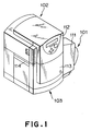
- Fig. 1 is a perspective view showing external appearance of one embodiment of a label printer according to the present invention;
- Fig. 2 is an exploded perspective view showing the label printer shown in Fig. 1 in a condition where a case cover is removed;
- Fig. 3 is a perspective view of the label printer shown in Fig. 1 in a condition where a front cover is opened;
- Fig. 4 is a section showing a mechanism of a print head station of the label printer of Fig. 1;
- Fig. 5 is a diagrammatic illustration showing an ink supply system in the label printer;
- Fig. 6 is a front elevation showing a general construction of the shown embodiment of a tube pump to be employed in the ink supply system;
- Fig. 7 is a front elevation showing a general constriction of the conventional tube pump to be employed in the ink supply system;
- Fig. 8 is a front elevation showing a ink strage chamber and an opening and closing mechanism of an atmosphere communication opening of the ink strage chamber;
- Fig. 9 is a front elevation showing the ink strage chamber shown in Fig. 8 in a condition where the atmosphere communication opening is opened;
- Fig. 10 is a section showing an internal structure of an ink cartridge;
- Fig. 11 is a plan view of the ink cartridge shown in Fig. 10;
- Fig. 12 is a bottom view of the ink cartridge of Fig. 10;
- Fig. 13 is a conceptual illustration showing a relationship between the ink cartridge shown in Fig. 10 and an ink supply needle unit;
- Fig. 14 is an enlarged section showing a structure of the ink supply needle unit;
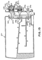
- Fig. 15 is a section showing an operating condition of the ink supply needle unit of Fig. 14 in an ink supply mode;
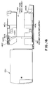
- Fig. 16 is a section in a condition where the ink cartridge is removed;
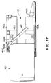
- Fig. 17 is a section showing an intermediate position in detaching of the ink cartridge;
- Fig. 18 is a section showing a condition where the ink cartridge is loaded;
- Fig. 19 is a section showing a structure of an under case frame in an ink cartridge receptacle chamber;
- Fig. 20 is an exploded section, in which the ink cartridge and the ink supply needle unit are shown in disassembled position;
- Fig. 21 is a section showing an intermediate condition in loading or unloading of the ink cartridge and the ink supply needle unit;
- Fig. 22 is a section showing the ink cartridge and the ink supply needle unit in the loaded condition;
- Fig. 23 is a front elevation of a head connector before assembling of the printer;
- Fig. 24 is a front elevation of the head connector corresponding to respective inks after assembling of printer;
- Fig. 25 is a front elevation of a transfer station;
- Fig. 26 is a right side elevation of the transfer station shown in Fig. 25;
- Fig. 27 is a section showing a positional relationship between a head cooling fin and fan; and
- Fig. 28 is a partial section showing a fin and an ink jet head.
- The preferred embodiment of the present invention will be discussed hereinafter in detail with reference to the accompanying drawings. In the following description, numerous specific details are set forth in order to provide a thorough understanding of the present invention. It will be obvious, however, to those skilled in the art that the present invention may be practiced without these specific details. In other instance, well-known structures are not shown in detail in order to unnecessary obscure the present invention.
- It should be noted that while the preferred embodiment will be discussed in terms of a printer employing a paper in a form of roll paper, in which a large number of labels are sequentially arranged on a released paper, as a printing medium, any type of printing medium in a form, a king and a material may be selected adapting the printer. For example, a cut paper may be employed as the printing medium. Also, as a material for the printing medium, film, cloth or any other material may be selected.
- Also, while the discussion given hereinafter is concentrated for application of the present invention to a label printer, the printer according to the present invention may be applicable for printing mediums, such as perforated continuous paper, name card, card and so forth. In the alternative, the printer according to the present invention can be in a form of a ticket printer and so forth. In short, the present invention is applicable for wide variety of forms of printers.
- Fig. 1 is a perspective view showing an external appearance of one embodiment of a label printer according to the present invention.
- The shown embodiment of the label printer employs a roll paper form paper, in which a plurality of labels are sequentially arranged on a released paper. The label printer generally comprises three pars, i.e. a roll
paper supply unit 101, aprinting head portion 102 and an inkcartridge receptacle portion 103. Acover 111 of the rollpaper supply unit 101 is provided in detachable fashion. By this,new roll paper 124 can be set (see Fig. 2). Theroll paper 124 to be stored in the rollpaper supply unit 101 is, as discussed later with reference to Fig. 2, fed by a paper feeding mechanism formed between theprinting head portion 102 and the inkcartridge receptacle portion 103. During feeding, printing is performed by a printing head in theprinting head portion 102 and ejected out of the apparatus through anejection opening 114. It should be appreciated that it is possible to connect a device for peeling off the label from the released paper ejected through theejection opening 114. Also, it is possible to connect a device for taking up the label together with the released paper, on which the labels are adhered. - The
printing head portion 102 is provided for pivoting about the rear end (in the drawing) serving as a pivot shaft with respect to the inkcartridge receptacle portion 103 for opening and closing. By this, it becomes possible to perform maintenance of the printing head of the printing head portion, the paper feeding mechanism and so forth and setting of theroll paper 124. At the front end portion of theprinting head portion 102, an operatingportion 112 including a lamp or liquid crystal indicator for indication of various condition of the label printer, and operating keys, is provided. - A
front cover 103 of the inkcartridge receptacle portion 103 can be opened and closed about a pivot axis which is established at the left side end in the shown case. By this, upon exchanging of the ink cartridge, the ink cartridge can be unloaded and loaded by opening thefront cover 113. - Fig. 2 is a perspective view of the label printer of Fig. 1, showing a condition where the
cover 111 of the rollpaper supply unit 101 is removed and theprinting head portion 102 is pivoted upwardly to be situated in the open position. Fig. 3 is a perspective view of the label printer of Fig. 1, in which thefront cover 113 of the inkcartridge receptacle portion 103 is held open. - As shown in Fig. 2, a
roll 126 on which theroll paper 124 is wound and which is stored in the rollpaper supply unit 101, is mounted on a pair of drive roller 301 (only one is shown). At this condition, the outer periphery of theroll 126 and thedrive roller 301 are kept in contact under a pressure due to own weight of theroll paper 124. At this condition, by rotation of thedrive roller 301 and so forth by a driving force of a not shown motor, theoutermost roll paper 124 is separated from the remaining innerside roll paper 124 and fed into the label printer. Supply of theroll paper 124 performed in substantially irrespective of feeding by a roll paper feeding mechanism 104 (detail is not shown) located between theprinting head portion 102 and the inkcartridge receptacle portion 103. Accordingly, for adjusting feeding between these two parts, in the supply of theroll paper 124, supply of theroll paper 124 is controlled to form a loop (not shown in Fig. 2) serving as a buffer. Namely, when a loop is not detected by a loop sensor (not shown) by feeding in the rollpaper feeding mechanism 104, thedrive roller 301 is driven to feed theroll paper 124 with forming the loop. - A
paper guide 131 is provided for sliding in a width direction of the storedroll 126. Namely, upon storing theroll paper 124, thepaper guide 131 is slide in a magnitude greater than the width of theroll paper 124 to place theroll 126 on thedrive roller 301. Thereafter, thepaper guide 131 is slide to the width of theroll 126 to contact a part thereof onto acore member 125 of theroll 126. By this, upon supplying of theroll paper 124, vibration of theroll paper 124 in the width direction at the upstream of the drive roller in the supply direction can be restricting by permitting constant fine vibration. It should be noted that, on thepaper guide 131, astopper 316 for fixing the slide position is provided. - In the feeding path of the
roll paper 124, in the vicinity of the feeding path in the rollpaper feeding mechanism 104, an obliquely feedingunit 128 is provided. The obliquely feedingunit 128 includes two obliquely feeding rollers (not shown) contacting with the lower surface of theroll paper 124 and obliquely feedingrolls roll paper 124. Two obliquely feeding rollers comprises drive roller opposing to the obliquely feedingroll 130 and driven by a driving force from the rollpaper feeding mechanism 104, and driven roller opposing to the obliquely feedingroll 129 and not driven by the driving force. Respective of the driving roller and the driven roller rotate in oblique direction relative to the feeding direction of the roll paper 124 (a rotation axis also lies in oblique with respect to a direction perpendicular to the feeding direction). Also, the obliquely feedingrolls rolls roll paper 124 to be fed to abut theroll paper 124 onto a predetermined guide in the distal side in the drawing. As a result, theroll paper 124 is applied a restricting force in a given direction in the feeding direction and thus can be fed stably without causing vibration in the feeding direction. - While it is neglected from illustration in Fig. 2, the roll
paper feeding mechanism 104 disposed between theprinting head portion 102 and the inkcartridge receptacle portion 103 is constructed with a plurality of belts arranged at the lower side of the roll paper 124 (thereafter arranged on the upper surface of the ink cartridge receptacle portion 103), rollers provided at upstream side and downstream side of the belt with respect to the feeding direction for driving the belts, and a wheel 141 (see Fig. 4) arranged at the lower surface of theprinting head portion 102 and transmitted the driving force via the predetermined belt among the belts. - In Fig. 3, the ink
cartridge receptacle portion 103 has fourcartridge receptacle chambers cartridge receptacle chambers shutters cartridge receptacle chambers shutters cartridge receptacle chambers - Fig. 4 is a front elevation showing a construction of a printing head station 151 (hereinafter referred to as "PHS"), as primary mechanism of the
printing head portion 102. - The
PHS 151 has ink-jet heads 155Y, 155M, 155C and 155Bk having ejection openings arranged beyond overall width of the label in the width direction of theroll paper 124 for performing printing with respect to the label arranged on theroll paper 124. As theseheads PHS 151 has an ink collection means for collecting ink ejected through ink ejection openings arranged in respective of theheads heads recovery system unit 153 having a cap preventing drying in the vicinity of the ink ejection openings. - In the
PHS 151, a drive system unit for shifting thehead holder unit 152 supporting theheads roll paper 124 and shifting therecovery type unit 153 for a given magnitude in horizontal direction along the feeding direction of theroll paper 124, and a cooling unit for cooling theheads - On the lower portion of the
PHS 151,wheels 141 are provided at both sides ofrespective heads - It should be noted that, while the discussion is given with generally dividing the label printer into three portions as set forth above, it is manner of course that not only the disclosed elements or mechanisms but also other elements and mechanisms are provided in respective portions. Discussion for other elements associated with the disclosed elements, control board, drive motor, ink supply system and so forth may be arranged appropriately . For the elements and mechanisms other than those disclosed in the foregoing discussion will be constructed with known elements and mechanisms.
- Fig. 5 is a diagrammatic illustration showing an ink supply system provided in the label printer set forth above.
- The shown embodiment of the ink supply system has
ink strage chambers 203 havingink cartridges 201 and an ink-jet heads 155 for respective colors, a plurality of buffer means 205 and 207. The ink supply in this system is performed by a pressure difference between tube pumps 209 and 211 and meniscus difference between respective elements. It should be noted that theink strage chamber 203, the plurality of buffer means 205 and 207, tube pumps 209 and 211 and so forth shown in Fig. 5 are provided for each ink similarly to the ink-jet head 155, theink cartridge 201, anink receptacle 215. Namely, the ink supply system shown in Fig. 5 is provided for each color of ink. - Discussion will be given hereinafter with respect to major ink supply modes in the shown embodiment of the ink supply system.
- At first, discussion will be given for a mode for maintaining the liquid level of the
ink strage chamber 203 at reference liquid level S. L. by supplying ink from theink cartridge 201 to theink strage chamber 203. In this mode, asolenoid 227 is driven to close theatmosphere communication opening 203A of theink strage chamber 203 by aplug 225. On the other hand, by the roller of thetube pump 211, atube 241 is crushed for closing. At this condition, the tube pump 208 is driven in counterclockwise direction (C.C.W.) to introduce a vacuum into thebuffer tank 205. At this time, by an one-way valve 219, ink does not flow into asupply path 237 from thehead 155. On the other hand, ink flows into the buffer tank only from the ink cartridge through thesupply path 231, in which an one-way valve 217 is in forward direction. When an ink level reaches atube 205A in thebuffer tank 205 by introduction of the ink, the ink flows into theink strage chamber 203 via the supply passage 238. By introduction of the ink, when the ink level in theink strage chamber 203 reaches the reference liquid level S.L., the excessive ink by further flow of the ink flows into theink cartridge 201 via thesupply path 235 to maintain the reference liquid level S.L. - Namely, this ink supply mode is performed by driving the
tube pump 209 for a given period at an appropriate timing other than the period of printing operation, in which ink is ejected from thehead 155. Thus, a printer control portion can maintain the reference liquid level S.L. in theink strage chamber 203 only by controlling the drive timing and driving period. The reference liquid level S.L. is held in a range of appropriate meniscus level with respect to the head to appropriately perform ink supply upon ejection of ink. - It should be noted that a
sensor 223 provided in theink strage chamber 203 is for detecting presence and absence of the ink and is used for detecting spent out of the ink in thecartridge tank 201 whensensor 223 does not detect presence of the ink even after driving of thetube pump 209 for a given period. - Next, discussion will be given for a supply mode upon ejection of ink in the ink-jet head.
- In this mode, the
atmosphere communication opening 203A of theink strage chamber 203 is held in open condition, and thetube pump ink strage chamber 203 is supplied to the ink-jet head 155 via two systems ofsupply paths ink strage chamber 203 and thehead 155. - The third to be discussed is a supply mode in recirculation of ink to be performed as one of ejection recovery process of the ink-
jet head 155. In this mode, theatmosphere communication opening 203A of theink strage chamber 203 is held open and twotube pumps head 155 via thesupply paths ink strage chamber 203, and in conjunction therewith, the ink flows into theink strage chamber 203 from thehead 155 via thesupply paths head 155 can be collected within theink strage chamber 203 together with the ink and finally discharge to the atmosphere via theatmosphere communication opening 203A. - On the other hand, upon recirculation of the ink as set forth above, the pressure in the
head 155 is desired to be maintained at a level slightly higher than the atmospheric pressure. By this, leakage of the ink via the ink ejection opening during recirculation can be minimized. However, in the ink supply system of the shown embodiment, pulsation of the pressure is large since thetube pump 209 is employed as a supply power source and synchronization control between twotube pumps head 155 during recirculation becomes further greater in magnitude. - Therefore, in the shown embodiment, by providing the plurality of buffer means 205 and 207 between the
head 155 and the tube pumps 209 and 211, pulsation of the tube pumps 209 and 211 is absorbed by these a plurality of buffer means 205 and 207. Therefore, during recirculation of the ink, the pressure within thehead 155 can be maintained at constant value in the appropriate level. - Further ink supply mode is a supply mode during pressurizing recovery to be performed as one of ejection recovery process similarly to the foregoing mode. In this mode, the
atmosphere communication opening 203A is held open and thetube pump 211 is held in the condition where thetube 241 is crushed by the roller. When thetube pump 209 is driven in the clockwise direction (C.W direction) at this condition, the ink is supplied to the head from theink strage chamber 203 via thesupply paths tube pump 211 is held inoperative. Therefore, the ink in thehead 155 is ejected to theink receptacle 215 via the ejection opening. Associating with ejection of the ink, high viscous ink within thehead 155 can be ejected. - The ink within the
ink receptacle portion 215 receiving the ejected ink by preparatory ejection performed as one of ejection recovery processes, is introduced into the waste ink storage portion of theink cartridge 201 via thesupply path 243 by atube pump 213. - Fig. 6 is a front elevation showing a detail of the tube pump 209 (211) to be employed in the ink supply system of Fig. 5, and Fig. 7 is a similar illustration showing the tube pump in the prior art.
- As shown in Fig. 6, the shown embodiment of the
tube pump 209 is formed with a semicircular recess is atube holder 212 which forms a support member. Along the semicircular portion, thetube 233 is arranged. At a position offset from the center of the semicircular, a roller rotating portion having a rotary axis is arranged. In the roller rotating portion,depression rollers respective depression rollers tube 233 to place thetube 233 in crushed position in a range of 65 in back and force direction at the lowermost position in the drawing. - On the other hand, the
tube holder 212 is pushed by means of aspring 216 to be held in the condition illustrated in Fig. 6. However, while thetube 233 is not depressed and thus in the through condition, it drives thecam 218 to rotate to pivot thetube holder 212 toward left in the drawing about anaxis 220. - Here, the difference between the shown embodiment of the tube pump 209 (see Fig. 6) and the conventional tube pump (see Fig. 7) is that, in the conventional tube pump, a
tube guide 214 is provided in the overall length for the portion of thetube 233 extending along the semicircular portion. In contrast to this, in the shown embodiment, theguide 210 is provided only portion except for the semicircular portion. (Theguide 210 is also provided symmetrically on the back side relative to the tube, in the drawing.) - With the construction of the guide in the shown embodiment, the guide restricts the
tube 233 at the portions in the vicinity of the depressing portion other than the portion where the tube is crushed by thedepression rollers 209A to 209D. In contrast to this, in the prior art shown in Fig. 7, theoverall tube 233 including the portion to be depressed is guided. Therefore, when thetube 233 rides over the guide in certain cause, it becomes possible that thetube 233 is cut off by the depression roller. - Thus, according to the shown embodiment, since the guide is not present at the portion where the
depression rollers 209A to 209D act, the possibility of cutting of thetube 233 can be successfully avoided even when large magnitude of offset is caused in thetube 233. - Figs. 8 and 9 are front elevations showing the detailed configuration of the
ink strage chamber 203 shown in Fig. 5 and the opening mechanism of theatmosphere communication opening 203A. Fig. 8 shows the closed condition of theatmosphere communication opening 203A and Fig. 9 shows the open condition thereof. - The opening mechanism for the atmosphere communication opening 20A is constructed as follow. A
seal lever 247 is pivotably supported by asupport shaft 249. Theplug 225 for contacting with the opening end of theatmosphere communication opening 203A is carried at one end of theseal lever 247. The other end of theseal lever 247 is connected to a plunger of asolenoid 227 for pivotal movement therewith. Here, thesolenoid 227 is so-called latch solenoid which can maintain the plunger in place when no power is supplied and is placed at a given position. On the other hand, theseal lever 247 is connected to atension spring 255 in the vicinity of the portion where theplug 225 is provided. The other end of thespring 255 is connected to a casing member holding thesolenoid 227. Also, theseal lever 247 is integrally formed with anoperation lever 251. - In the opening and closing mechanism as set forth above, as shown in Fig. 5, power supply for the
solenoid 227 is controlled depending upon respective ink supply modes to operate the actuating member. In conjunction therewith, by the action of thespring 255, theseal lever 247 is pivoted. By this, theplug 225 contacts and released from the opening end of theatmosphere communication opening 203A to open and close theatmosphere communication opening 203A. - In addition to the opening and closing mechanism as set forth above, upon transportation for shipping of the label printer or moving of the installation position of the printer, the
operation lever 251 is operated as shown by arrow in Fig. 9 to establish closed position shown in Fig. 8. By this, even when the label printer subjects vibration during transportation, moving or so forth, ink will never leak through theatmosphere communication opening 203A. - Fig. 10 is a section of the side showing the internal structure of the ink cartridge illustrated in Fig. 5, Fig. 11 is a plan view and Fig. 12 is a bottom view of the ink cartridge.
- As shown in these drawings, the
ink cartridge 201 includes anink storage chamber 257 and a wasteink storage chamber 260. At the end of the ink storage chamber, rubber plugs 265 are provided at two portions for passing ink supply needles 275 which will be discussed later. These rubber plugs 265 have a construction sandwiches by the case member of the ink cartridge, anink absorbing member 263 and arubber plug holder 267 except for the portions whereneedles ink absorbing member 263. Therefore, it can prevent contamination of the inside of the label printer by the ink adhering on the supply needles 275C and 279C and plugging of thesupply nozzles - The waste
ink storage chamber 260 is formed with a two stages of storage portions communicated at one ends. A portion, in which theink supply needle 279C passes through is provided corresponding to the lower stage storage portion. Namely, in thewaste storage chamber 260, theink supply needle 279C connected to thesupply path 243 as illustrated in Fig. 5 passes through. By this, the waste ink discharged in the ejection recovery process and so forth flows into the lower stage portion of theink storage chamber 260. Generally, in the whole body of theink storage chamber 260 is filled with anink absorbing member 259. Thus, the waste ink flowing into the lower stage storage portion of thewater storage chamber 260 is absorbed by theink absorbing member 259. According to introduction of the waste ink, the region of holding the waste ink among the waste ink gradually extends to theink absorbing member 259 to partly exude out of the ink absorbing member. On the other hand, adjacent to the end of the wasteink absorbing member 259, a partitioning wall 261A is provided. By this, before the waster ink amount exceeds the holding capacity of theink absorbing member 259, the exuded ink as set forth above is prevented from moving to the portion at the right side where theink absorbing member 259 is not filled. Accumulatively, the waste ink among introduced tends to be increased to exceed the holding capacity of theink absorbing member 259, Then, the exuded waste ink is then transferred to cause overflow to elevate the liquid lever, When the increased level fills up the wasted in the wasteink storage chamber 260 can be detected. Thus, it becomes possible to promote exchanging of theink cartridge 201. - The inside of the waste
ink storage chamber 260 is adapted to communicate with the outside via a Microtext (tradename: Nitto Denko K.K.) disposed therebetween. By this, leakage of the waste ink can be prevented, and in conjunction therewith, evaporation of the moisture content in the waste ink becomes possible. - On the upper surface of the
ink cartridge 201, anidentification seal 273 is adhered for identifying the kind of the ink stored therein. Also, at the front end of theink cartridge 201, aresistant seal 271 for electrical detection of loading of theink cartridge 201 and the kind of ink, is adhered. - Fig. 13 is an illustration showing a loading condition of the
ink cartridge 201 to the label printer. Namely, Fig. 13 shows the condition where respective ink supply needles 275C pierce therubber plug 265 of theink cartridge 201. - The
supply needle unit 275 shown in Fig. 13 is connected to the supply path 235 (see Fig. 5) for recirculating the ink from theink strage chamber 203. When theink cartridge 201 is not loaded, thevalve 275A is biased by means of a spring (not shown) toward left in the drawing to block communication between aconnection tube 275D and theneedle 275C. When theink cartridge 201 is loaded, by an action of a not shown lever upon loading operation of the ink cartridge which will be discussed with reference to Fig. 20 and so forth, thevalve 275A is opened against the spring force to establish communication between theconnection tube 275D and theneedle 275C. - A
supply needle unit 277 is adapted to be connected to the supply path 231 (see Fig. 5) for supplying ink to the buffer tank 206 (see Fig. 5). Irrespective of loading or unloading condition of theink cartridge 201, avalve 277A is normally biased toward left by aspring 277B to block communication between aconnection tube 277D and theneedle 277C, as shown in Fig. 14. - The
supply needle unit 277 establishes the communication between theconnection tube 277D and theneedle 277C in the following condition. As discussed with respect to Fig. 5, when thetube pump 209 is driven in counterclockwise direction in the ink supply mode to theink strage chamber 203, vacuum is introduced into theconnection tube 277D via thebuffer tank 205. By this, as shown in Fig. 15, thevalve 277A is shifted toward right against the biasing force of thespring 277B to establish communication between theconnection tube 277D and theneedle 277C. Then, the ink in theink cartridge 201 is supplied to thebuffer tank 205. Thus, thesupply needle unit 277 serves to perform function of thecheck valve 217 shown in Fig. 5. - A
supply needle unit 279 is connected to the supply path 243 (see Fig. 5) for the waste ink, in which a connection tube 279D and aneedle 279C are constantly communicated with each other. - Fig. 16 to 18 are illustration showing detailed construction of the
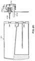
shutter 142 of thecartridge receptacle chamber 140 discussed with respect to Fig. 3 and loading operation of theink cartridge 201 to thecartridge receptacle chamber 140. - As shown in Figs. 16 to 18, the
shutter 142 is pivoted at a predetermined position on anupper frame 140U of thecartridge receptacle chamber 140 and slidably engaged with astopper lever 142A for sliding movement within a given range. On the other hand, thestopper lever 142A is similarly pivoted at a point frontwardly shifted from the pivot point of theshutter 142. Thestopper lever 142A is restricted frontward pivoting range by astopper 142C. With the construction set forth above, theshutter 142 is prevented from opening by pulling it frontwardly. - Upon insertion of the
ink cartridge 201, as shown in Fig. 17, theink cartridge 201 is pushed into the ink cartridge receptacle chamber with abutting the front end shoulder thereof with thestopper lever 142A, By this, theink cartridge 201 finally abut to astopper 140S provided on alower frame 140L of thecartridge receptacle chamber 140 and thus is placed at the loading position shown in Fig. 18. At the loading position, theresistant seal 271 provided on the upper surface of theink cartridge 201 comes into contact with anelectrode 281 at the side of the main body and anelectrode 269 for detection of the waste ink also contacts with anelectrode 282 at the side of the main body. At this time, since the most part of the tip end portion of theshutter 142 is cut out as shown in Fig. 3, theshutter 142 is prevented from contacting with theresistant seal 271. - Fig. 19 is a diagrammatic longitudinal section showing the entire construction of the
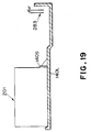
lower frame 140L of thecartridge receptacle chamber 140 set forth above. - The
lower frame 140L is formed into tub-shaped configuration to accommodate therein thecartridge receptacle chamber 140 and other ink supply systems shown in Fig. 5. With such construction, even when leakage of ink is cased in the ink supply system, the ink will not flow out of thelower frame 140L. Furthermore, thelower frame 140L is inclined toward the rear side (right side in Fig. 19) and asensor 283 for detecting the ink accumulated in thelower frame 140L is provided in the vicinity of the lowermost position of the lower frame. By this, presence of a given amount of leaked ink can be detected. - Figs. 20 to 22 are illustration for explaining positional relationship between the
needle 275C of thesupply needle unit 275 and theink cartridge 201, in the loading position. - At first, immediately before contacting the
needle 275C with therubber plug 265 of theink cartridge 201 associating with loading of theink cartridge 201, no force is exerted on thelever 275F. Therefore, thevalve 275A is biased by thespring 275B to be held in the position blocking communication between theconnection tube 275D and theneedle 275C. - Next, as the
ink cartridge 201 is further advanced for loading, as shown in Fig. 21, thelever 275F of thesupply needle unit 275 comes into contact with a part of theink cartridge 201. At this timing, a portion having the communication opening of the tip end of theneedle 275C already passes through therubber plug 265 and placed within theink cartridge 201. On the other hand, at this time, thelever 275F has just come into contact with the part of theink cartridge 201, the depression force of theink cartridge 201 is not yet acted onlever 275F. Accordingly, the communication between theconnection tube 275D and theneedle 275C is still blocked. - Next, by further advancement of the
ink cartridge 201 in the loading direction, as shown in Fig. 22, the depression force of theink cartridge 201 acts on thelever 275F to depress the latter. By this, aconnection lever 275E is shifted toward right in Fig. 22 about one end serving as pivot point. As a result, theconnection lever 275E and thevalve 275A are shifted rightwardly against the biasing force of thespring 275B to establish communication between theconnection tube 275D and theneedle 275C. - As can be clear from the discussion with respect to Figs. 20 to 22, the
supply needle unit 275 for ink recirculation from theink strage chamber 203 to thecartridge 201 initially penetrate the tip portion of the needle carrying the communication opening into theink cartridge 201 and subsequently open thevalve 275A, associating with insertion of theink cartridge 201 into thecartridge receptacle chamber 140 upon loading. In other words, the relationship of the length of thelever 275F and the length of theneedle 275C is determined to certainly cause the sequence of actions set forth above. - With the construction set forth above, a problem that the
valve 275A is opened before theneedle 275C is inserted into theink cartridge 201 to cause the ink from theink strage chamber 203 to leak into the apparatus through the communication opening of theneedle 275C, can be successfully prevented. - Fig. 23 to 26 are illustration showing a
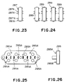
head connector 289 and atransfer station 285 provided at a part of the ink supply path and establish connection of the supply tubes. - In the shown embodiment, since four kinds of inks, i.e. yellow (Y), magenta (M), cyan (C) and black (Bk), are employed, four ink supply paths are present. Accordingly, it becomes necessary that respective head connectors and the kinds of the inks are corresponded and the head connectors corresponded to the kinds of inks are set corresponding to the
transfer station 285. - Therefore, as shown in Fig. 23, the
head connector 289 in assembling of printer has respectively fourbosses 287A at both sides. During assembling, thebosses 287A located at the positions corresponding to respective kinds of inks are cut away to form thehead connector 289 after completion of assembling. - On the other hand, as shown in the front elevation of Fig. 25 and right side elevation of Fig. 26, the
transfer station 285 pairs ofbosses 285A are diagonally arranged. Respective positions of thebosses 285A corresponds to the positions of the bosses of thehead connectors 287 which are cut away for identifying the corresponding kind of the ink. With the construction set forth above, thehead connector 289 will never set at erroneous position. Thus, a problem of color mixing can be successfully prevented. - Fig. 27 is a section showing a part of the
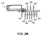
printing head 102 shown in Fig. 1 and so forth. - On each ink-
jet head 155, as shown in Fig. 28, a plurality offins 291 extending in overall length of the head in the longitudinal direction are provided. For generating an air flow along the longitudinal direction of the fines, afan 293 is provided. Thefan 293 is adapted to be driven by a not shown motor. At the front side and rear side of thefan 293,ducts duct 295A is communicated with the atmosphere via alouver 297 formed in a par of thecover member 114. By this, relatively low temperature air can be taken from the outside of the printer. - In a printer employing an ink-jet system, for appropriately managing loading and unloading of an ink cartridge and waste ink and for obtaining appropriate ink supply system for an ink-jet head, an ink storage chamber (257) and a waste ink storage chamber (260) of the ink cartridge (201) is formed integrally. Most part of the waste ink storage chamber (260) is filled with an absorbing member (259). Also, at a portion where a supply needle is pierced and removed at the front end face of the cartridge (201), an ink absorbing member (263) is provided. Also, among two stage structure of the waste ink storage chamber, a portion where the absorbing member is not present is defined by a partitioning wall (260A) to detect the ink exuded from the absorbing member and stored in the portion beyond the partitioning wall (260A) is detected by a detection electrode (269). On the other hand, when the ink is forcedly supplied from the ink strage chamber to the ink-jet head by driving the tube pump (209) in clockwise direction, the ink supply is performed via a buffer tank (205). Therefore, pulsation of the ink pressure due to driving of the tube pump (209) will not affect for the ink-jet head to make the pressure at the ink-jet head stable to tisfactorily perform ejection recovery process.
Claims (18)
- A printer having an ink-jet head ejecting an ink for performing printing on a printing medium, characterized by comprising:
an ink cartridge storing the ink to be supplied to said ink-jet head;
ink storage means for temporarily storing the ink to be supplied from said ink cartridge to said ink-jet head, having an atmosphere communication opening and having an ink path for returning an excess amount of ink to said ink cartridge;
buffer means connected to said ink cartridge via an ink path having an one-way valve permitting only flow of the ink from said ink cartridge, connected to said ink storage means via an ink path having a tube pump and connected to said ink-jet head via an ink passage having an one-way valve permitting only flow of the ink toward head ink-jet head, for maintaining the ink amount at a predetermined amount; and
opening and closing means for opening and closing said atmosphere communication opening of said ink storage means. - A printer as claimed in claim 1, which further comprises second buffer means connected to said ink-jet head via an ink path and connected to said ink strage chamber via an ink path having a second tube pump, for maintaining the ink amount at the predetermined amount.
- A printer as claimed in claim 1, characterized in that said tube pump guides a tube at portions other than a portion where a depression roller of the tube pump acts on the tube.
- A printer as claimed in claim 2, characterized in that said tube pump guides a tube at portions other than a portion where a depression roller of the tube pump acts on the tube.
- A printer as claimed in claim 1, characterized in that said ink path for returning the excess amount of ink in said ink storage means to said ink cartridge includes a needle unit having a needle communicated with the inside of said ink cartridge associating with loading operation of said ink cartridge, said needle unit having a valve for establishing communication between the inside of the ink cartridge and said needle by loading operation of said ink cartridge.
- A printer as claimed in claim 5, characterized in that a positional relationship between said ink cartridge and said needle unit upon loading of the ink cartridge is that a communication opening of said needle penetrates within said ink cartridge and subsequently said valve is opened.
- A printer as claimed in claim 1, characterized in that said ink path connecting said ink cartridge and said buffer means includes a needle unit having a needle to be communicated with the inside of said ink cartridge associating with loading of said ink cartridge, said needle unit having a valve establishing communication between said ink cartridge and said needle by a suction pressure transmitted via said buffer means by driving of said tube pump.
- A printer as claimed in claim 1, which further comprises means for manually opening and closing said atmosphere communication opening of said ink storage means.
- A printer as claimed in claim 1, characterized in that said ink cartridge includes an ink storage chamber for storing the ink to be supplied to said ink-jet head and a waste ink storage chamber having an absorbing member for holding and storing the ink discharged from the printer, and said ink storage chamber and said waste ink storage chamber are formed integrally, and said waste ink storage chamber has two stage construction.
- A printer as claimed in claim 1, which further comprises a cartridge receptacle chamber, to which said ink cartridge is detachably loaded, and having a shutter member pivotably provided at an insertion opening for said ink cartridge and engaging with the outer surface of the ink cartridge when said ink cartridge is inserted for loading,
said ink cartridge being provided with a resistant member depending upon information relating said ink cartridge, on the outer surface thereof; and
said shutter member is formed into a configuration having a cut-out portion so as not to interfere with said resistant member upon engagement with the outer surface of said ink cartridge, - A printer as claimed in claim 1, characterized in that said printer is a label printer.
- A printer as claimed in claim 1, wherein said ink-jet head ejects the ink by generating a bubble of the ink utilizing a thermal energy and ejecting the ink by generation of the bubble.
- An ink cartridge to be employed in a printer performing printing on a printing medium, characterized by comprising:
an ink storage chamber for storing an ink to be supplied to said printer;
a waste ink storage chamber storing the ink discharged from said printer and having an absorbing member holding said ink;
said ink storage chamber and said waste ink storage chamber being formed integrally and said waste ink storage chamber has two stage structure. - An ink cartridge as claimed in claim 13, characterized in that said waste ink storage chamber is provided with a detection sensor for detecting presence of the ink.
- An ink cartridge as claimed in claim 14, characterized in that said detection sensor is located at an upper stage of said two stage structure and defines by a given height of wall, in which said absorbing member is not present.
- An ink cartridge as claimed in claim 13, characterized in that an ink inlet portion of said waste ink storage chamber is provided at the lower stage of said two stage structure.
- An ink cartridge as claimed in claim 13, characterized in that ink supply for said printer and introduction of discharge of ink from said printer is performed a supply needle inserted within said ink cartridge, and an absorbing member is provided at least at the portion where said supply needle is inserted.
- An ink cartridge for storing an ink to be used by a printer for performing printing on a printing medium, characterized in that ink supply for said printer and introduction of discharge of ink from said printer is performed a supply needle inserted within said ink cartridge, and an absorbing member is provided at least at the portion where said supply needle is inserted.
Applications Claiming Priority (6)
| Application Number | Priority Date | Filing Date | Title |
|---|---|---|---|
| JP272767/94 | 1994-11-07 | ||
| JP27277494 | 1994-11-07 | ||
| JP27276794A JP3247558B2 (en) | 1994-11-07 | 1994-11-07 | Printer |
| JP27277494A JP3167553B2 (en) | 1994-11-07 | 1994-11-07 | Ink cartridge and label printer using the cartridge |
| JP27276794 | 1994-11-07 | ||
| JP272774/94 | 1994-11-07 |
Publications (3)
| Publication Number | Publication Date |
|---|---|
| EP0710561A2 true EP0710561A2 (en) | 1996-05-08 |
| EP0710561A3 EP0710561A3 (en) | 1997-01-29 |
| EP0710561B1 EP0710561B1 (en) | 2002-04-10 |
Family
ID=26550368
Family Applications (1)
| Application Number | Title | Priority Date | Filing Date |
|---|---|---|---|
| EP95117329A Expired - Lifetime EP0710561B1 (en) | 1994-11-07 | 1995-11-03 | Printer and ink cartridge to be employed in the same |
Country Status (3)
| Country | Link |
|---|---|
| US (2) | US5801736A (en) |
| EP (1) | EP0710561B1 (en) |
| DE (1) | DE69526302T2 (en) |
Cited By (10)
| Publication number | Priority date | Publication date | Assignee | Title |
|---|---|---|---|---|
| EP0768183A2 (en) * | 1995-10-13 | 1997-04-16 | Canon Kabushiki Kaisha | Ink tank with ink container and waste ink container |
| EP0928694A1 (en) * | 1997-08-28 | 1999-07-14 | Seiko Epson Corporation | Ink cartridge having waste ink absorbing function |
| WO2000015440A1 (en) * | 1998-09-16 | 2000-03-23 | Wincor Nixdorf Gmbh & Co Kg | Ink jet printer with a holder for a printing-ink container |
| EP1004446A2 (en) * | 1998-11-24 | 2000-05-31 | Eastman Kodak Company | Insertable cartridge for digital camera with ink jet printer |
| EP1063095A2 (en) | 1999-06-25 | 2000-12-27 | Eastman Kodak Company | Ink jet printer for photofinishing |
| EP1063096A2 (en) | 1999-06-25 | 2000-12-27 | Eastman Kodak Company | Ink jet printer for photofinishing |
| EP1295723A1 (en) * | 2001-09-19 | 2003-03-26 | Seiko Epson Corporation | Ink cartridge and its manufacturing method |
| SG145558A1 (en) * | 1998-11-26 | 2008-09-29 | Seiko Epson Corp | Method of storing data |
| ES2385407A1 (en) * | 2008-10-31 | 2012-07-24 | Durst Phototechnik Digital Technology Gmbh | Ink supply system and method of operating an ink supply system of an inkjet printer |
| CN107984906A (en) * | 2016-10-26 | 2018-05-04 | 精工爱普生株式会社 | Fluid Supplying apparatus and printing equipment |
Families Citing this family (44)
| Publication number | Priority date | Publication date | Assignee | Title |
|---|---|---|---|---|
| EP0710561B1 (en) * | 1994-11-07 | 2002-04-10 | Canon Aptex Inc. | Printer and ink cartridge to be employed in the same |
| JP3684022B2 (en) | 1996-04-25 | 2005-08-17 | キヤノン株式会社 | Liquid replenishment method, liquid discharge recording apparatus, and ink tank used as a main tank of the liquid discharge recording apparatus |
| US6302516B1 (en) * | 1997-01-14 | 2001-10-16 | Markem Corporation | Ink supply system for ink jet printhead |
| US6786420B1 (en) | 1997-07-15 | 2004-09-07 | Silverbrook Research Pty. Ltd. | Data distribution mechanism in the form of ink dots on cards |
| US6618117B2 (en) | 1997-07-12 | 2003-09-09 | Silverbrook Research Pty Ltd | Image sensing apparatus including a microcontroller |
| US7551201B2 (en) | 1997-07-15 | 2009-06-23 | Silverbrook Research Pty Ltd | Image capture and processing device for a print on demand digital camera system |
| US6879341B1 (en) | 1997-07-15 | 2005-04-12 | Silverbrook Research Pty Ltd | Digital camera system containing a VLIW vector processor |
| SG116449A1 (en) * | 1997-07-15 | 2005-11-28 | Silverbrook Res Pty Ltd | Ink and media cartridge with axial ink chambers. |
| US6624848B1 (en) | 1997-07-15 | 2003-09-23 | Silverbrook Research Pty Ltd | Cascading image modification using multiple digital cameras incorporating image processing |
| US7110024B1 (en) | 1997-07-15 | 2006-09-19 | Silverbrook Research Pty Ltd | Digital camera system having motion deblurring means |
| US6690419B1 (en) | 1997-07-15 | 2004-02-10 | Silverbrook Research Pty Ltd | Utilising eye detection methods for image processing in a digital image camera |
| US6293662B1 (en) | 1998-01-19 | 2001-09-25 | Canon Kabushiki Kaisha | Ink tank coupling method, ink jet recording apparatus, and ink tank |
| AUPP702098A0 (en) | 1998-11-09 | 1998-12-03 | Silverbrook Research Pty Ltd | Image creation method and apparatus (ART73) |
| CN1550879B (en) * | 1998-11-09 | 2012-05-02 | 西尔弗布鲁克研究有限公司 | Digital print cartridge and ink jet cartridge |
| AUPQ056099A0 (en) | 1999-05-25 | 1999-06-17 | Silverbrook Research Pty Ltd | A method and apparatus (pprint01) |
| JP2002234180A (en) | 2001-02-09 | 2002-08-20 | Canon Inc | Ink feed unit, ink feed mechanism and ink jet recorder |
| US6698870B2 (en) * | 2002-07-25 | 2004-03-02 | Hewlett-Packard Development Company, L.P. | Ball check valve for bulk ink supply system |
| JP2004090432A (en) * | 2002-08-30 | 2004-03-25 | Seiko Epson Corp | Liquid injection device, tank for discharging liquid of liquid injection device, and liquid discharging method of liquid injection device |
| US7033012B2 (en) * | 2003-01-31 | 2006-04-25 | Hewlett-Packard Development Company, L.P. | Ink containment apparatus and methods for inkjet printers |
| JP2005053212A (en) * | 2003-07-18 | 2005-03-03 | Seiko Epson Corp | Liquid container |
| US7452062B2 (en) * | 2003-07-18 | 2008-11-18 | Seiko Epson Corporation | Liquid container with structure for controlling leaked liquid |
| US7758172B2 (en) * | 2003-07-18 | 2010-07-20 | Seiko Epson Corporation | Injection apparatus and a valve device provided in a passage |
| US7472986B2 (en) * | 2004-03-31 | 2009-01-06 | Fujifilm Corporation | Liquid droplet discharge head and liquid droplet discharge device |
| JP3952054B2 (en) * | 2004-09-28 | 2007-08-01 | 富士フイルム株式会社 | Image forming apparatus |
| WO2006064036A1 (en) * | 2004-12-17 | 2006-06-22 | Agfa Graphics Nv | Ink circulation system for inkjet printing |
| JP2006192638A (en) * | 2005-01-12 | 2006-07-27 | Fuji Photo Film Co Ltd | Inkjet recording apparatus |
| JP2006305902A (en) * | 2005-04-28 | 2006-11-09 | Brother Ind Ltd | Ink jet recorder |
| US7556340B2 (en) * | 2005-05-31 | 2009-07-07 | Brother Kogyo Kabushiki Kaisha | Ink jet recording apparatus |
| JP4533274B2 (en) * | 2005-08-11 | 2010-09-01 | キヤノン株式会社 | Liquid coating apparatus and inkjet recording apparatus |
| EP1961574B1 (en) * | 2005-12-09 | 2013-01-23 | Sharp Kabushiki Kaisha | Liquid drop ejection unit and liquid drop ejection device |
| JP5002232B2 (en) * | 2006-10-06 | 2012-08-15 | キヤノン株式会社 | Inkjet recording device |
| AT507142B1 (en) * | 2008-08-14 | 2011-05-15 | Durst Phototechnik Digital Technology Gmbh | INK SUPPLY SYSTEM AND METHOD FOR CLEANING AN INK SUPPLY SYSTEM |
| JP5549231B2 (en) * | 2010-01-13 | 2014-07-16 | セイコーエプソン株式会社 | Printing device |
| WO2011132256A1 (en) * | 2010-04-19 | 2011-10-27 | キヤノン株式会社 | Printing device |
| US8544991B2 (en) | 2010-12-29 | 2013-10-01 | Funai Electric Co., Ltd. | Consumable supply item, fluid reservoir and recirculation system for micro-fluid applications |
| JP2013000986A (en) * | 2011-06-17 | 2013-01-07 | Brother Industries Ltd | Inkjet printer |
| US9180674B2 (en) * | 2013-02-08 | 2015-11-10 | R.R. Donnelley & Sons Company | System and method for supplying ink to an inkjet cartridge |
| US8851136B1 (en) * | 2013-03-13 | 2014-10-07 | Alexander V. Drynkin | Laboratory tube printer and labeler |
| CN104339871B (en) * | 2013-07-30 | 2017-01-18 | 京瓷办公信息系统株式会社 | Flow path opening/closing device and inkjet recording apparatus provided with the flow path opening/closing device |
| JP6179989B2 (en) | 2014-06-30 | 2017-08-16 | キヤノンファインテックニスカ株式会社 | Liquid container, liquid ejection device, and liquid recovery method |
| JP6769057B2 (en) * | 2016-03-14 | 2020-10-14 | ブラザー工業株式会社 | Printing equipment |
| JP6665649B2 (en) * | 2016-04-15 | 2020-03-13 | セイコーエプソン株式会社 | cartridge |
| CN207291314U (en) | 2016-05-09 | 2018-05-01 | R.R.当纳利父子公司 | Ink feeding unit |
| JP7057190B2 (en) * | 2018-03-30 | 2022-04-19 | キヤノン株式会社 | Liquid discharge device |
Family Cites Families (28)
| Publication number | Priority date | Publication date | Assignee | Title |
|---|---|---|---|---|
| DE3042997A1 (en) * | 1980-11-14 | 1982-07-01 | Olympia Werke Ag, 2940 Wilhelmshaven | Typing head nozzle ink collector - has moistened surface placed against edge between nozzle face and underside |
| JPS5828385A (en) | 1981-08-12 | 1983-02-19 | Matsushita Electric Ind Co Ltd | Magnetic ink recorder |
| JPS58108153A (en) * | 1981-12-22 | 1983-06-28 | Seiko Epson Corp | Ink cartridge |
| JPS58194550A (en) * | 1982-05-10 | 1983-11-12 | Canon Inc | Ink cassette for multicolor ink jet printer |
| JPS58194561A (en) | 1982-05-11 | 1983-11-12 | Canon Inc | Recording apparatus |
| JPS59131837U (en) * | 1983-02-23 | 1984-09-04 | シャープ株式会社 | Ink cartridge device for inkjet printers |
| DE3428434C2 (en) * | 1983-08-02 | 1995-09-14 | Canon Kk | Printing device |
| GB2147975B (en) * | 1983-10-11 | 1987-07-08 | Dick Co Ab | Valve for ink marking systems |
| US4695851A (en) * | 1984-02-24 | 1987-09-22 | Canon Kabushiki Kaisha | Ink jet printer |
| US4677488A (en) | 1985-07-25 | 1987-06-30 | Zenith Electronics Corporation | Video system with television receiver and teletext processor capable of switching external RGB signals |
| US4772900A (en) * | 1985-10-22 | 1988-09-20 | Canon Kabushiki Kaisha | Ink-jet recording apparatus |
| JPS63247048A (en) * | 1987-04-03 | 1988-10-13 | Canon Inc | Liquid jet recorder |
| JP2611257B2 (en) | 1987-09-17 | 1997-05-21 | セイコーエプソン株式会社 | ink cartridge |
| US4965596A (en) * | 1988-02-09 | 1990-10-23 | Canon Kabushiki Kaisha | Ink jet recording apparatus with waste ink distribution paths to plural cartridges |
| US4837585A (en) * | 1988-04-25 | 1989-06-06 | Eastman Kodak Company | Continuous ink jet printer having improved system for reducing pressure variations |
| JP2725281B2 (en) | 1988-05-27 | 1998-03-11 | セイコーエプソン株式会社 | Ink collection container |
| JPH035159A (en) * | 1989-06-02 | 1991-01-10 | Canon Inc | Waste ink container in ink jet recorder |
| JP3112459B2 (en) * | 1989-06-05 | 2000-11-27 | セイコーエプソン株式会社 | ink cartridge |
| EP1234675B1 (en) * | 1989-08-05 | 2007-05-09 | Canon Kabushiki Kaisha | Ink jet recording apparatus and ink cartridge for the apparatus |
| US5221935A (en) * | 1990-02-15 | 1993-06-22 | Canon Kabushiki Kaisha | Waste ink receiving cartridge and ink recording apparatus using said cartridge |
| ATE139941T1 (en) * | 1990-02-26 | 1996-07-15 | Canon Kk | INK JET RECORDING APPARATUS AND METHOD FOR CLEANING THE RECORDING HEAD |
| JPH03247462A (en) * | 1990-02-27 | 1991-11-05 | Canon Inc | Ink cartridge and recording device |
| JP2924098B2 (en) | 1990-06-12 | 1999-07-26 | セイコーエプソン株式会社 | ink cartridge |
| JPH04364960A (en) * | 1991-06-12 | 1992-12-17 | Canon Inc | Head cartridge for ink jet recording apparatus |
| JPH0612044A (en) | 1992-06-26 | 1994-01-21 | Mita Ind Co Ltd | Character pattern information generation device |
| CA2101017C (en) * | 1992-07-24 | 1999-10-26 | Masahiko Higuma | Ink jet cartridge, ink jet head and printer |
| US6286921B1 (en) * | 1993-04-06 | 2001-09-11 | Sharp Kabushiki Kaisha | Ink cartridge of an ink jet printer and an ink jet printer including an ink cartridge |
| EP0710561B1 (en) * | 1994-11-07 | 2002-04-10 | Canon Aptex Inc. | Printer and ink cartridge to be employed in the same |
-
1995
- 1995-11-03 EP EP95117329A patent/EP0710561B1/en not_active Expired - Lifetime
- 1995-11-03 DE DE69526302T patent/DE69526302T2/en not_active Expired - Lifetime
- 1995-11-06 US US08/553,867 patent/US5801736A/en not_active Expired - Lifetime
-
1998
- 1998-06-15 US US09/094,626 patent/US6283585B1/en not_active Expired - Lifetime
Non-Patent Citations (1)
| Title |
|---|
| None |
Cited By (19)
| Publication number | Priority date | Publication date | Assignee | Title |
|---|---|---|---|---|
| EP0768183A3 (en) * | 1995-10-13 | 1998-02-11 | Canon Kabushiki Kaisha | Ink tank with ink container and waste ink container |
| US5953031A (en) * | 1995-10-13 | 1999-09-14 | Canon Kabushiki Kaisha | Ink tank with ink container and waste ink container |
| EP0768183A2 (en) * | 1995-10-13 | 1997-04-16 | Canon Kabushiki Kaisha | Ink tank with ink container and waste ink container |
| US6281911B1 (en) | 1997-08-28 | 2001-08-28 | Seiko Epson Corporation | Ink cartridge having waste ink absorbing function |
| EP0928694A1 (en) * | 1997-08-28 | 1999-07-14 | Seiko Epson Corporation | Ink cartridge having waste ink absorbing function |
| EP0928694A4 (en) * | 1997-08-28 | 1999-07-28 | ||
| WO2000015440A1 (en) * | 1998-09-16 | 2000-03-23 | Wincor Nixdorf Gmbh & Co Kg | Ink jet printer with a holder for a printing-ink container |
| EP1004446A2 (en) * | 1998-11-24 | 2000-05-31 | Eastman Kodak Company | Insertable cartridge for digital camera with ink jet printer |
| EP1004446A3 (en) * | 1998-11-24 | 2000-07-05 | Eastman Kodak Company | Insertable cartridge for digital camera with ink jet printer |
| SG145558A1 (en) * | 1998-11-26 | 2008-09-29 | Seiko Epson Corp | Method of storing data |
| EP1063095A2 (en) | 1999-06-25 | 2000-12-27 | Eastman Kodak Company | Ink jet printer for photofinishing |
| US6382850B1 (en) | 1999-06-25 | 2002-05-07 | Eastman Kodak Company | Ink jet printer for photofinishing |
| EP1063096A2 (en) | 1999-06-25 | 2000-12-27 | Eastman Kodak Company | Ink jet printer for photofinishing |
| EP1295723A1 (en) * | 2001-09-19 | 2003-03-26 | Seiko Epson Corporation | Ink cartridge and its manufacturing method |
| US6796642B2 (en) | 2001-09-19 | 2004-09-28 | Seiko Epson Corporation | Ink cartridge and its manufacturing method |
| US6986569B2 (en) | 2001-09-19 | 2006-01-17 | Seiko Epson Corporation | Ink cartridge and its manufacturing method |
| ES2385407A1 (en) * | 2008-10-31 | 2012-07-24 | Durst Phototechnik Digital Technology Gmbh | Ink supply system and method of operating an ink supply system of an inkjet printer |
| CN107984906A (en) * | 2016-10-26 | 2018-05-04 | 精工爱普生株式会社 | Fluid Supplying apparatus and printing equipment |
| CN107984906B (en) * | 2016-10-26 | 2020-12-15 | 精工爱普生株式会社 | Liquid supply device and printing device |
Also Published As
| Publication number | Publication date |
|---|---|
| DE69526302T2 (en) | 2002-11-14 |
| EP0710561B1 (en) | 2002-04-10 |
| US5801736A (en) | 1998-09-01 |
| EP0710561A3 (en) | 1997-01-29 |
| US6283585B1 (en) | 2001-09-04 |
| DE69526302D1 (en) | 2002-05-16 |
Similar Documents
| Publication | Publication Date | Title |
|---|---|---|
| US5801736A (en) | Ink jet printer with cartridge having integral ink storage chamber | |
| EP2496421B1 (en) | Printing system with fixed printheads and movable vacuum platen | |
| US20110228289A1 (en) | Inkjet printer | |
| JP5205851B2 (en) | Inkjet printer | |
| KR100314876B1 (en) | Inkjet printer | |
| JPH04214360A (en) | Ink jet recording device, ink tank cartridge for said device and manufacture of said cartridge | |
| KR20010013262A (en) | Method and apparatus for securing an ink container | |
| JP2001253087A (en) | Replaceable ink container for ink jet printing system | |
| EP0768183B1 (en) | Ink tank with ink container and waste ink container | |
| PL203149B1 (en) | Method and apparatus for providing ink container extraction characteristics to a printing system | |
| JP2009233876A (en) | Inkjet printer | |
| US7431438B2 (en) | Ink cartridge, recording apparatus employing ink cartridge, and manufacturing method for ink cartridge | |
| US20020113836A1 (en) | Image forming method and apparatus therefor | |
| JP3217645B2 (en) | Ink jet recording apparatus and ink ejection recovery method in the apparatus | |
| JP3247558B2 (en) | Printer | |
| JPH10119297A (en) | Device for detecting residue of ink | |
| EP0435666B1 (en) | Suction recovery device and ink jet recording apparatus with the device | |
| JP2000289222A (en) | Liquid ejection recording apparatus, liquid supply method, liquid removing method, and liquid replacing method for the liquid ejection recording apparatus | |
| JP2007313829A (en) | Inkjet recording apparatus and ink recovery method | |
| US7101027B2 (en) | Inkjet printer | |
| JP3167553B2 (en) | Ink cartridge and label printer using the cartridge | |
| JP3323831B2 (en) | Ink tank and recording device | |
| JP2001253086A (en) | Replaceable ink container for inkjet printing system | |
| JP2009233860A (en) | Inkjet printer | |
| EP0884185B1 (en) | Image forming method and apparatus therefor |
Legal Events
| Date | Code | Title | Description |
|---|---|---|---|
| PUAI | Public reference made under article 153(3) epc to a published international application that has entered the european phase |
Free format text: ORIGINAL CODE: 0009012 |
|
| AK | Designated contracting states |
Kind code of ref document: A2 Designated state(s): DE FR GB IT |
|
| PUAL | Search report despatched |
Free format text: ORIGINAL CODE: 0009013 |
|
| AK | Designated contracting states |
Kind code of ref document: A3 Designated state(s): DE FR GB IT |
|
| 17P | Request for examination filed |
Effective date: 19970523 |
|
| 17Q | First examination report despatched |
Effective date: 19980506 |
|
| GRAG | Despatch of communication of intention to grant |
Free format text: ORIGINAL CODE: EPIDOS AGRA |
|
| GRAG | Despatch of communication of intention to grant |
Free format text: ORIGINAL CODE: EPIDOS AGRA |
|
| GRAH | Despatch of communication of intention to grant a patent |
Free format text: ORIGINAL CODE: EPIDOS IGRA |
|
| GRAH | Despatch of communication of intention to grant a patent |
Free format text: ORIGINAL CODE: EPIDOS IGRA |
|
| REG | Reference to a national code |
Ref country code: GB Ref legal event code: IF02 |
|
| GRAA | (expected) grant |
Free format text: ORIGINAL CODE: 0009210 |
|
| AK | Designated contracting states |
Kind code of ref document: B1 Designated state(s): DE FR GB IT |
|
| PG25 | Lapsed in a contracting state [announced via postgrant information from national office to epo] |
Ref country code: IT Free format text: LAPSE BECAUSE OF FAILURE TO SUBMIT A TRANSLATION OF THE DESCRIPTION OR TO PAY THE FEE WITHIN THE PRESCRIBED TIME-LIMIT;WARNING: LAPSES OF ITALIAN PATENTS WITH EFFECTIVE DATE BEFORE 2007 MAY HAVE OCCURRED AT ANY TIME BEFORE 2007. THE CORRECT EFFECTIVE DATE MAY BE DIFFERENT FROM THE ONE RECORDED. Effective date: 20020410 Ref country code: FR Free format text: LAPSE BECAUSE OF FAILURE TO SUBMIT A TRANSLATION OF THE DESCRIPTION OR TO PAY THE FEE WITHIN THE PRESCRIBED TIME-LIMIT Effective date: 20020410 |
|
| REF | Corresponds to: |
Ref document number: 69526302 Country of ref document: DE Date of ref document: 20020516 |
|
| PG25 | Lapsed in a contracting state [announced via postgrant information from national office to epo] |
Ref country code: GB Free format text: LAPSE BECAUSE OF NON-PAYMENT OF DUE FEES Effective date: 20021103 |
|
| EN | Fr: translation not filed | ||
| PLBE | No opposition filed within time limit |
Free format text: ORIGINAL CODE: 0009261 |
|
| STAA | Information on the status of an ep patent application or granted ep patent |
Free format text: STATUS: NO OPPOSITION FILED WITHIN TIME LIMIT |
|
| 26N | No opposition filed |
Effective date: 20030113 |
|
| GBPC | Gb: european patent ceased through non-payment of renewal fee | ||
| PGFP | Annual fee paid to national office [announced via postgrant information from national office to epo] |
Ref country code: DE Payment date: 20141029 Year of fee payment: 20 |
|
| REG | Reference to a national code |
Ref country code: DE Ref legal event code: R071 Ref document number: 69526302 Country of ref document: DE |