EP0711609A2 - Atomizer - Google Patents
Atomizer Download PDFInfo
- Publication number
- EP0711609A2 EP0711609A2 EP95307936A EP95307936A EP0711609A2 EP 0711609 A2 EP0711609 A2 EP 0711609A2 EP 95307936 A EP95307936 A EP 95307936A EP 95307936 A EP95307936 A EP 95307936A EP 0711609 A2 EP0711609 A2 EP 0711609A2
- Authority
- EP
- European Patent Office
- Prior art keywords
- air
- deflector
- gas
- atomizer according
- outlet
- Prior art date
- Legal status (The legal status is an assumption and is not a legal conclusion. Google has not performed a legal analysis and makes no representation as to the accuracy of the status listed.)
- Granted
Links
Images


Classifications
-
- A—HUMAN NECESSITIES
- A61—MEDICAL OR VETERINARY SCIENCE; HYGIENE
- A61M—DEVICES FOR INTRODUCING MEDIA INTO, OR ONTO, THE BODY; DEVICES FOR TRANSDUCING BODY MEDIA OR FOR TAKING MEDIA FROM THE BODY; DEVICES FOR PRODUCING OR ENDING SLEEP OR STUPOR
- A61M11/00—Sprayers or atomisers specially adapted for therapeutic purposes
- A61M11/06—Sprayers or atomisers specially adapted for therapeutic purposes of the injector type
-
- A—HUMAN NECESSITIES
- A61—MEDICAL OR VETERINARY SCIENCE; HYGIENE
- A61M—DEVICES FOR INTRODUCING MEDIA INTO, OR ONTO, THE BODY; DEVICES FOR TRANSDUCING BODY MEDIA OR FOR TAKING MEDIA FROM THE BODY; DEVICES FOR PRODUCING OR ENDING SLEEP OR STUPOR
- A61M11/00—Sprayers or atomisers specially adapted for therapeutic purposes
- A61M11/001—Particle size control
- A61M11/002—Particle size control by flow deviation causing inertial separation of transported particles
-
- B—PERFORMING OPERATIONS; TRANSPORTING
- B05—SPRAYING OR ATOMISING IN GENERAL; APPLYING FLUENT MATERIALS TO SURFACES, IN GENERAL
- B05B—SPRAYING APPARATUS; ATOMISING APPARATUS; NOZZLES
- B05B7/00—Spraying apparatus for discharge of liquids or other fluent materials from two or more sources, e.g. of liquid and air, of powder and gas
- B05B7/0012—Apparatus for achieving spraying before discharge from the apparatus
-
- A—HUMAN NECESSITIES
- A61—MEDICAL OR VETERINARY SCIENCE; HYGIENE
- A61M—DEVICES FOR INTRODUCING MEDIA INTO, OR ONTO, THE BODY; DEVICES FOR TRANSDUCING BODY MEDIA OR FOR TAKING MEDIA FROM THE BODY; DEVICES FOR PRODUCING OR ENDING SLEEP OR STUPOR
- A61M15/00—Inhalators
- A61M15/0091—Inhalators mechanically breath-triggered
-
- A—HUMAN NECESSITIES
- A61—MEDICAL OR VETERINARY SCIENCE; HYGIENE
- A61M—DEVICES FOR INTRODUCING MEDIA INTO, OR ONTO, THE BODY; DEVICES FOR TRANSDUCING BODY MEDIA OR FOR TAKING MEDIA FROM THE BODY; DEVICES FOR PRODUCING OR ENDING SLEEP OR STUPOR
- A61M16/00—Devices for influencing the respiratory system of patients by gas treatment, e.g. mouth-to-mouth respiration; Tracheal tubes
- A61M16/0003—Accessories therefor, e.g. sensors, vibrators, negative pressure
- A61M2016/0015—Accessories therefor, e.g. sensors, vibrators, negative pressure inhalation detectors
- A61M2016/0018—Accessories therefor, e.g. sensors, vibrators, negative pressure inhalation detectors electrical
-
- A—HUMAN NECESSITIES
- A61—MEDICAL OR VETERINARY SCIENCE; HYGIENE
- A61M—DEVICES FOR INTRODUCING MEDIA INTO, OR ONTO, THE BODY; DEVICES FOR TRANSDUCING BODY MEDIA OR FOR TAKING MEDIA FROM THE BODY; DEVICES FOR PRODUCING OR ENDING SLEEP OR STUPOR
- A61M16/00—Devices for influencing the respiratory system of patients by gas treatment, e.g. mouth-to-mouth respiration; Tracheal tubes
- A61M16/0003—Accessories therefor, e.g. sensors, vibrators, negative pressure
- A61M2016/003—Accessories therefor, e.g. sensors, vibrators, negative pressure with a flowmeter
- A61M2016/0033—Accessories therefor, e.g. sensors, vibrators, negative pressure with a flowmeter electrical
Definitions
- the present invention relates to atomizers and, in particular, to atomizers of the type which include a gas exit, at least one outlet in the region of the gas exit and a deflector for deflecting gas issuing from the gas exit across the at least one outlet whereby a substance to be atomized is drawn out of the at least one outlet and atomized.
- atomizers atomize liquids or powders into the gas.
- atomizers of the above type operate continuously whether atomization is required or not. Strictly speaking, when such atomizers, frequently called nebulisers, are used in medical applications, atomization is only required during the inhalation phase of a breathing cycle so that a drug can be administered by deposition in the lungs. In practice a patient usually inhales for about 30 percent of the breathing cycle, consequently, use of a continuously operating atomizer results in a large proportion of the atomized drug being wasted.
- Some designs of medical atomizer overcome such wastage by giving the patient a trigger to start the atomization when they begin to inhale. Such a trigger controlled type of atomizer is not satisfactory since the patient must coordinate inhalation with trigger operation.
- a gas duct leads gas under pressure to a gas exit
- a reservoir for holding the substance to be atomized is formed around the base of the gas duct
- a sleeve placed around the gas duct defines a passageway through which the substance to be atomized may pass to at least one outlet.
- a fixed deflector in the form of a bar is disposed in line with the gas outlet so that gas issuing from the gas exit is deflected so as to pass over the outlet or outlets.
- the passage of gas over each outlet draws the substance to be atomised from the reservoir, through the passageway to each outlet.
- the deflected gas atomizes the substance, and atomized particles of the substance are carried away during the inhalation phase of the patient since the patient breathes air or gas in through the atomizer some of the drug is lost while the patient is not inhaling.
- Atomizers are used in other applications.
- powders or liquid may be sprayed from a jet, the liquid or powder being atomized and entrained by a propellant.
- operation is controlled by a valve for releasing propellant.
- the valve When the valve is released, the spraying operation is stopped and some of the liquid or powder collects in the jet since insufficient propellant has been released.
- the collected spray either dries to block the jet or is propelled by a re-started spraying operation in large droplets. Where paint is being sprayed, this causes splatter and uneven deposition on a surface to be painted.
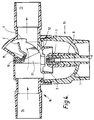
- an atomizer includes a gas duct 6 which leads gas under pressure to a gas exit 4 within a jet head 3.
- the gas duct 6 passes through a wall of a reservoir 7 within which a substance to be atomised is held.
- a sleeve 8 is disposed around the jet head 3 and the gas duct 6. Passages are formed between the inner surface of the sleeve 8 and the outer surface of the gas duct 6 for leading the substance to be atomized from the reservoir 7 to outlets 5 in the jet head adjacent to the gas exit 4.
- a deflector 1 must be placed in the path of the pressurised gas exiting from the gas exit 4 so that it is redirected to pass directly over the outlets 5.
- This flow of pressure air draws the substance to be atomized from the reservoir 7, through the passage between the sleeve 8 and the gas duct 6 to the outlets 5. The flow of pressure air atomizes the substance as the substance leaves the outlets 5.
- a downwardly and outwardly shaped baffle 9 is disposed around the jet head 3 to the atomized substance downwards before it is carried away. It is important that the substance is atomized into very fine droplets.
- the substance to be atomized is a drug for administering to a patient by lung deposition. The finer the droplets, the deeper into the lungs the drug will pass. This maximises the deposition of the drug. Larger droplets collect on the inside of the baffle 9 where they coalesce to drop back down into the reservoir 7.
- the atomizer also includes an air inlet 13 and an air outlet 14.
- air inlet 13 In the above-mentioned medical application, as a patient inhales, ambient air is drawn into the atomizer through the inlet 13. The air then passes into the region of the air exit 4 and outlets 5 where droplets are entrained by the inhaled ambient air. The air then passes down under the baffle 9 before passing upwardly and out via the air outlet 14 carrying droplets of the drug to the patient. This action is described in more detail in our British Patent applications 9219327.5 and 9311614.3 which are hereby imported into this description in their entirety.
- a planar arcuate gas deflector 1 is mounted above the gas exit to be movable about a pivot in that plane.
- the gas deflector 1 may be disposed across the gas exit 4, in which case atomization takes place, or may be disposed away from the gas exit 4, in which case no atomization takes place.
- a vane 2 is joined to the deflector bar 1 so as to be pivotally mounted and to move with the deflector bar 1.
- the flap 2 responds to the breathing pattern of a patient by moving around the pivot.
- the vane When the apparatus is not in use, the vane assumes the position shown in Figure 1 in which the gas deflector is not disposed across the gas exit. The vane forms a partial seal against a curved surface 12 (shown in outline). Even when pressure gas is issuing from the gas exit, no atomization takes place since the deflector is not disposed in the path of the gas.
- the vane must move only a few degrees before the deflector bar 1 is brought into position to commence atomization, but must move a few more degrees before breaking the seal between the flap and the curved surface to permit ambient air to enter the nebulizer. This ensures that the deflector is fully in position and atomizing cleanly before the ambient air passes through the atomizer to carry the droplets away.
- the deflector extends further from the pivot than the flap so that the deflector can be positioned very close to the gas exit without obstruction from the flap.
- the curved surface 12 against which the vane seals therefore includes an arcuate slot through which the deflector may pass.
- the vane 2 assumes the position shown in Figure 3 wherein the deflector bar 1 remains in the path of the gas exit so that atomization takes place, but excess air passes directly from the air inlet 13 to the air outlet 14 without entraining the atomized substance.
- the main reason for this is that the efficiency of entrainment of droplets decreases where air passes through the atomizer too quickly since a proportion of droplets will impact against the walls of the atomizer.
- a typical optimum flow rate is of the order of twenty five litres per minute.
- the vane 2 When the patient exhales, the vane 2 is displaced to a position as shown in figure 4 where the deflector is displaced such that it is not in the path of the gas exit. Atomization therefore does not occur, and so no drug is wasted.
- the vane allows exhaled air to pass directly from the air outlet 14 to the air inlet 13 without having to pass through the atomizing chamber.
- the combination of the vane 2 and the deflector 1 therefore constitutes a one-way valve.
- the vane 2 When the patient is not breathing in or out, the vane 2 is biassed towards the position shown in Figure 1.
- the vane 2 and deflector 1 are mounted on a rubber tongue 11 extending from a fixed rubber block 10. The vane 2 and deflector 1 are therefore resiliently mounted.
- the atomizer shown in Figures 1 to 4 includes three separable units.
- a base unit 15 includes the reservoir 7, the gas duct 6, the jet head 3 and outlets 5.
- the reservoir 7 includes a threaded rim.
- An upper unit 16 includes three air inlet 13, and the air outlet 14.
- the baffle 9, sleeve 8, frame members 17, the vane 2, gas deflector 1, the rubber tongue 11 and the fixed rubber block 10 constitute the third unit. Separation of the third unit permits the atomizer to be more easily cleaned.
- the vane 2 and gas deflector are connected to the air inlet 13 in the upper unit 16, and to the baffle 9 since the gas deflector 1 must pass through a slot in the baffle.
- the sleeve 8 may be part of the base unit 15, or part of the third unit.
- Figures 5 and 6 show the vane 2 and deflector 1 mounted on the fixed rubber block and rubber tongue.
- the rubber tongue 11 is held at the ends by the frame members 17 so that when the tongue 11 is bent by the vane, a load is applied.
- the vane 2 and deflector 1 are attached directly to the tongue 11 so that they are pivotally displaceable.
- Figure 7 shows a second embodiment of this invention in which the base unit 15 is exactly as described in relation to Figures 1 to 4.
- the vane 2 and deflector 1 are also mounted as described above.
- the main difference in this second embodiment is that the air outlet 14 leading to a patient extends vertically from the atomizer as shown in Figure 7. Drug laden air does not have to pass around a sharp corner into the air outlet 14 once it has passed around the baffle 9. Fewer drug droplets will collect on the inner surface of the air outlet 14.
- the lower edge of the vane 2 forms a seal with the curved surface 12 as explained above.
- the vane 2 also includes two other edges which must be sealed.
- the vane 2 swings between two vertical wedgeshaped frame members 17 which form a seal so that flow of air to bypass the vane 2 is restricted when the vane 2 is disposed in any of the positions shown in Figures 1, 2 or 7.
- the frame members 17 also act as supports for the fixed rubber block 10.
- the frame members 17 may extend from the baffle 9, from the edge of the curved surface 12 or from the base unit 15. Where the frame members extend from the edge of the curved surface 12, the vane 2, deflector 1 and rubber block 10 are all mounted on the frame members 17 and within the upper unit 16.
- the rubber block 10 is replaced by a metal spring eg, a leaf spring which permits the vane 2 and deflector 1 to be pivotally moveable in the same manner as described in relation to the rubber block 10 and tongue 11.
- a metal spring eg, a leaf spring which permits the vane 2 and deflector 1 to be pivotally moveable in the same manner as described in relation to the rubber block 10 and tongue 11.
- the vane 2 is omitted, and the deflector is movable into and out of the stream of gas issuing from the gas exit according to the breathing pattern of a patient.
- the vane is replaced by a flow sensor which detects when a patient begins to inhale and moves the deflector 1 into the path of gas issuing from the gas exit.
- the deflector is a bar which is moveable perpendicularly or laterally relevant to the longitudinal extent of the bar.
- the deflector 1 is displaceable up and down in line with the gas issuing from the gas outlet. Once the deflector is raised above a certain height, atomization ceases to take place.
- the deflector is not a straight bar, but is of any suitable shape for deflecting the gas across the outlets to cause atomization.
- the deflector- may, for example, be a spherical ball disposed in the path of gas exiting the gas exit.
- the deflector may be a longitudinal blade movable into the path of the gas in the longitudinal direction of the blade.
- the atomizer is used for producing a spray.
- This spray may be liquid droplets or powder particles.
- the spray may contain a drug.
- This spray producing apparatus may be used for producing sprays of paint droplets, perfume droplets or any other suitable liquids or powders.
- a base unit 15 of Figures 1 - 4 may be used to produce a gas exit 4 and outlets 5 for the substance to be atomized.
- a moveable deflector 1 is displaceable by a user. The user first activates a compressor which sends gas through the gas duct.
- a mechanical compressor may be used, although this could be substituted for an aerosol propellant.
- the propellant then carries the droplets or powder through an outlet jet to form a spray.
- a two-stage button can be used whereby atomization only takes place when the button is fully depressed while gas issues from the gas exit when the button is only partially depressed.
- the deflector bar 1 is housed entirely within the baffle 9 so that any liquid which collects on the deflector bar merely drips back into the reservoir, or if it is sprayed from the deflector bar by the flow of gas from the gas exit 4, is collected on the underside of the baffle 9 whereupon it coalesces and drops back down into the reservoir 7.
- Figure 8 shows the nebulizer in a position where the patient is not inhaling.
- the segment shaped deflector bar 1 is disposed outside the line of gas exiting from the gas exit 4 so that nebulization does not take place.
- the segment is pivoted at a pivot point 21, and is also connected to the vane or flap 2.
- a proportion of the inhaled air passes directly from the air inlet 13 to the air outlet 14 as shown by arrow A.
- the flow of air for entraining droplets B Once the flow of air for entraining droplets B has passed beneath the baffle 9, it returns around the outside of the baffle 9 to rejoin the through flow of air A.
- a further advantage of this embodiment is that only a certain volume of air passes under the baffle 9 in a given time.
- the nebulizer works most effectively when the flow of air for entraining droplets is of the rate of about 25 litres per minute. If this rate of flow of air is much greater than this or much less than this, the effectiveness of entrainment decreases. This means that if the patient inhales sharply, the rate of through flow of air A increases without significantly altering the flow of air for entraining droplets B passing beneath the baffle.
Abstract
Description
- The present invention relates to atomizers and, in particular, to atomizers of the type which include a gas exit, at least one outlet in the region of the gas exit and a deflector for deflecting gas issuing from the gas exit across the at least one outlet whereby a substance to be atomized is drawn out of the at least one outlet and atomized. These atomizers atomize liquids or powders into the gas.
- Most conventional atomizers of the above type operate continuously whether atomization is required or not. Strictly speaking, when such atomizers, frequently called nebulisers, are used in medical applications, atomization is only required during the inhalation phase of a breathing cycle so that a drug can be administered by deposition in the lungs. In practice a patient usually inhales for about 30 percent of the breathing cycle, consequently, use of a continuously operating atomizer results in a large proportion of the atomized drug being wasted.
- Some designs of medical atomizer overcome such wastage by giving the patient a trigger to start the atomization when they begin to inhale. Such a trigger controlled type of atomizer is not satisfactory since the patient must coordinate inhalation with trigger operation.
- In one conventional atomizer a gas duct leads gas under pressure to a gas exit, a reservoir for holding the substance to be atomized is formed around the base of the gas duct, and a sleeve placed around the gas duct defines a passageway through which the substance to be atomized may pass to at least one outlet. A fixed deflector in the form of a bar is disposed in line with the gas outlet so that gas issuing from the gas exit is deflected so as to pass over the outlet or outlets. The passage of gas over each outlet draws the substance to be atomised from the reservoir, through the passageway to each outlet. The deflected gas atomizes the substance, and atomized particles of the substance are carried away during the inhalation phase of the patient since the patient breathes air or gas in through the atomizer some of the drug is lost while the patient is not inhaling.
- Atomizers are used in other applications. For example, powders or liquid may be sprayed from a jet, the liquid or powder being atomized and entrained by a propellant. In conventional sprays, operation is controlled by a valve for releasing propellant. When the valve is released, the spraying operation is stopped and some of the liquid or powder collects in the jet since insufficient propellant has been released. The collected spray either dries to block the jet or is propelled by a re-started spraying operation in large droplets. Where paint is being sprayed, this causes splatter and uneven deposition on a surface to be painted.
- It is an object of this invention to reduce at least some of the above disadvantages of the above-mentioned prior art.
- The present invention is defined in the appended claims.
- Embodiments of the invention are described below by way of example only with reference to the accompanying drawings in which:
- Figure 1 shows a first embodiment of the invention in a relaxed position;
- Figure 2 shows the first embodiment of the invention in a first operational position in which atomization takes place;
- Figure 3 shows the first embodiment of he invention in a second operational position in which atomization takes place;
- Figure 4 shows the first embodiment of the invention in a third operational position in which no atomization takes place;
- Figures 5 and 6 show one embodiment of the flap valve and gas deflector;
- Figure 7 shows a second embodiment of the invention in a second operational position in which atomization takes place,
- Figure 8 shows a further embodiment of the invention in which the movable baffle bar is located beneath the baffle, and
- Figure 9 shows the further embodiment during inhalation by a patient.
- Referring to Figures 1 to 4, an atomizer includes a
gas duct 6 which leads gas under pressure to agas exit 4 within ajet head 3. Thegas duct 6 passes through a wall of areservoir 7 within which a substance to be atomised is held. Asleeve 8 is disposed around thejet head 3 and thegas duct 6. Passages are formed between the inner surface of thesleeve 8 and the outer surface of thegas duct 6 for leading the substance to be atomized from thereservoir 7 tooutlets 5 in the jet head adjacent to thegas exit 4. For atomization of the substance to take place, a deflector 1 must be placed in the path of the pressurised gas exiting from thegas exit 4 so that it is redirected to pass directly over theoutlets 5. This flow of pressure air draws the substance to be atomized from thereservoir 7, through the passage between thesleeve 8 and thegas duct 6 to theoutlets 5. The flow of pressure air atomizes the substance as the substance leaves theoutlets 5. - A downwardly and outwardly shaped
baffle 9 is disposed around thejet head 3 to the atomized substance downwards before it is carried away. It is important that the substance is atomized into very fine droplets. In medical applications, the substance to be atomized is a drug for administering to a patient by lung deposition. The finer the droplets, the deeper into the lungs the drug will pass. This maximises the deposition of the drug. Larger droplets collect on the inside of thebaffle 9 where they coalesce to drop back down into thereservoir 7. - The atomizer also includes an
air inlet 13 and anair outlet 14. In the above-mentioned medical application, as a patient inhales, ambient air is drawn into the atomizer through theinlet 13. The air then passes into the region of theair exit 4 andoutlets 5 where droplets are entrained by the inhaled ambient air. The air then passes down under thebaffle 9 before passing upwardly and out via theair outlet 14 carrying droplets of the drug to the patient. This action is described in more detail in our British Patent applications 9219327.5 and 9311614.3 which are hereby imported into this description in their entirety. - A planar arcuate gas deflector 1 is mounted above the gas exit to be movable about a pivot in that plane. The gas deflector 1 may be disposed across the
gas exit 4, in which case atomization takes place, or may be disposed away from thegas exit 4, in which case no atomization takes place. - A
vane 2 is joined to the deflector bar 1 so as to be pivotally mounted and to move with the deflector bar 1. Theflap 2 responds to the breathing pattern of a patient by moving around the pivot. - When the apparatus is not in use, the vane assumes the position shown in Figure 1 in which the gas deflector is not disposed across the gas exit. The vane forms a partial seal against a curved surface 12 (shown in outline). Even when pressure gas is issuing from the gas exit, no atomization takes place since the deflector is not disposed in the path of the gas.
- When a patient inhales, ambient air is drawn into the atomizer through the
air inlet 13. Thevane 2 is displaced into the position shown in Figure 2 permitting and directing the ambient air to pass into the region of the gas exit before being directed downwardly and outwardly around the baffle. The air then escapes via theair outlet 14 to the patient. The displacement of the flap moves the deflector bar into the path of the gas issuing from the gas exit. Atomization therefore begins as soon as the patient begins to breath in. The atomized drug is carried away by the air passing through the atomizer. The vane must move only a few degrees before the deflector bar 1 is brought into position to commence atomization, but must move a few more degrees before breaking the seal between the flap and the curved surface to permit ambient air to enter the nebulizer. This ensures that the deflector is fully in position and atomizing cleanly before the ambient air passes through the atomizer to carry the droplets away. - The deflector extends further from the pivot than the flap so that the deflector can be positioned very close to the gas exit without obstruction from the flap. The
curved surface 12 against which the vane seals therefore includes an arcuate slot through which the deflector may pass. - If the patient inhales sharply or quickly, the
vane 2 assumes the position shown in Figure 3 wherein the deflector bar 1 remains in the path of the gas exit so that atomization takes place, but excess air passes directly from theair inlet 13 to theair outlet 14 without entraining the atomized substance. The main reason for this is that the efficiency of entrainment of droplets decreases where air passes through the atomizer too quickly since a proportion of droplets will impact against the walls of the atomizer. A typical optimum flow rate is of the order of twenty five litres per minute. - When the patient exhales, the
vane 2 is displaced to a position as shown in figure 4 where the deflector is displaced such that it is not in the path of the gas exit. Atomization therefore does not occur, and so no drug is wasted. The vane allows exhaled air to pass directly from theair outlet 14 to theair inlet 13 without having to pass through the atomizing chamber. The combination of thevane 2 and the deflector 1 therefore constitutes a one-way valve. - When the patient is not breathing in or out, the
vane 2 is biassed towards the position shown in Figure 1. Thevane 2 and deflector 1 are mounted on arubber tongue 11 extending from a fixedrubber block 10. Thevane 2 and deflector 1 are therefore resiliently mounted. - The atomizer shown in Figures 1 to 4 includes three separable units. A
base unit 15 includes thereservoir 7, thegas duct 6, thejet head 3 andoutlets 5. Thereservoir 7 includes a threaded rim. Anupper unit 16 includes threeair inlet 13, and theair outlet 14. Thebaffle 9,sleeve 8,frame members 17, thevane 2, gas deflector 1, therubber tongue 11 and the fixedrubber block 10 constitute the third unit. Separation of the third unit permits the atomizer to be more easily cleaned. Thevane 2 and gas deflector are connected to theair inlet 13 in theupper unit 16, and to thebaffle 9 since the gas deflector 1 must pass through a slot in the baffle. Thesleeve 8 may be part of thebase unit 15, or part of the third unit. - Figures 5 and 6 show the
vane 2 and deflector 1 mounted on the fixed rubber block and rubber tongue. Therubber tongue 11 is held at the ends by theframe members 17 so that when thetongue 11 is bent by the vane, a load is applied. Thevane 2 and deflector 1 are attached directly to thetongue 11 so that they are pivotally displaceable. - Figure 7 shows a second embodiment of this invention in which the
base unit 15 is exactly as described in relation to Figures 1 to 4. Thevane 2 and deflector 1 are also mounted as described above. The main difference in this second embodiment is that theair outlet 14 leading to a patient extends vertically from the atomizer as shown in Figure 7. Drug laden air does not have to pass around a sharp corner into theair outlet 14 once it has passed around thebaffle 9. Fewer drug droplets will collect on the inner surface of theair outlet 14. - Referring to Figures 3, 4 and 7, the lower edge of the
vane 2 forms a seal with thecurved surface 12 as explained above. Thevane 2 also includes two other edges which must be sealed. Thevane 2 swings between two verticalwedgeshaped frame members 17 which form a seal so that flow of air to bypass thevane 2 is restricted when thevane 2 is disposed in any of the positions shown in Figures 1, 2 or 7. In the first and second embodiments shown in Figures 1 to 7, theframe members 17 also act as supports for the fixedrubber block 10. Theframe members 17 may extend from thebaffle 9, from the edge of thecurved surface 12 or from thebase unit 15. Where the frame members extend from the edge of thecurved surface 12, thevane 2, deflector 1 andrubber block 10 are all mounted on theframe members 17 and within theupper unit 16. - According to another embodiment (not shown), the
rubber block 10 is replaced by a metal spring eg, a leaf spring which permits thevane 2 and deflector 1 to be pivotally moveable in the same manner as described in relation to therubber block 10 andtongue 11. - In a further embodiment (not shown) the
vane 2 is omitted, and the deflector is movable into and out of the stream of gas issuing from the gas exit according to the breathing pattern of a patient. The vane is replaced by a flow sensor which detects when a patient begins to inhale and moves the deflector 1 into the path of gas issuing from the gas exit. In this embodiment the deflector is a bar which is moveable perpendicularly or laterally relevant to the longitudinal extent of the bar. - In another embodiment the deflector 1 is displaceable up and down in line with the gas issuing from the gas outlet. Once the deflector is raised above a certain height, atomization ceases to take place.
- In yet a further embodiment, the deflector is not a straight bar, but is of any suitable shape for deflecting the gas across the outlets to cause atomization. The deflector-may, for example, be a spherical ball disposed in the path of gas exiting the gas exit. The deflector may be a longitudinal blade movable into the path of the gas in the longitudinal direction of the blade.
- In yet another embodiment (not shown) of this invention, the atomizer is used for producing a spray. This spray may be liquid droplets or powder particles. In medical applications, the spray may contain a drug. This spray producing apparatus may be used for producing sprays of paint droplets, perfume droplets or any other suitable liquids or powders. A
base unit 15 of Figures 1 - 4 may be used to produce agas exit 4 andoutlets 5 for the substance to be atomized. A moveable deflector 1 is displaceable by a user. The user first activates a compressor which sends gas through the gas duct. For paint spraying, a mechanical compressor may be used, although this could be substituted for an aerosol propellant. The user then moves the deflector into the path of the gas issuing from thegas exit 4 to start atomization. The propellant then carries the droplets or powder through an outlet jet to form a spray. The user stops atomization before stopping the flow of gas from the gas exit. This keeps the outlet jet clean and free from paint and the like. A two-stage button can be used whereby atomization only takes place when the button is fully depressed while gas issues from the gas exit when the button is only partially depressed. - Under certain conditions, although 95% of the gas issuing from the
gas exit 4 is deflected to either side of the deflector bar 1, a small amount hits the baffle bar depositing the substance to be atomized on the deflector bar 1. The gas which hits the baffle bar drives the liquid along the baffle bar towards the ends where the liquid can collect on top of thebaffle 9 so that it is lost to the atomizer system. The whole dose of medicament is then not available to be administered to the patient. Furthermore, in some arrangements, as the deflector bar is moved out of the flow of gas issuing from thegas exit 4, the liquid that is running along the edge of the deflector bar 1 is sprayed into the top of the nebulizer where it collects without returning back to thereservoir 7. Referring now to Figures 8 and 9, the deflector bar 1 is housed entirely within thebaffle 9 so that any liquid which collects on the deflector bar merely drips back into the reservoir, or if it is sprayed from the deflector bar by the flow of gas from thegas exit 4, is collected on the underside of thebaffle 9 whereupon it coalesces and drops back down into thereservoir 7. Figure 8 shows the nebulizer in a position where the patient is not inhaling. The segment shaped deflector bar 1 is disposed outside the line of gas exiting from thegas exit 4 so that nebulization does not take place. The segment is pivoted at apivot point 21, and is also connected to the vane orflap 2. When a patient inhales, air is drawn into the nebulizer throughair inlet 13, and deflects the vane orflap 2 moving the deflector bar 1 into line with the gas exit thus causing atomization of the substance to occur. For clarity, theoutlets 5 and thesleeve 8 are not shown in the Figure. However the jet head is arranged in the same way as described in connection with Figures 1 to 7. The atomization of the substance causes the pressure beneath thebaffle 9 to be decreased thereby drawing part of the inhaled air under thebaffle 9 as shown by arrow B. Thebaffle 9 includes anaperture 20 for permitting the flow of air for entraining droplets B to enter beneath thebaffle 9. A proportion of the inhaled air passes directly from theair inlet 13 to theair outlet 14 as shown by arrow A. Once the flow of air for entraining droplets B has passed beneath thebaffle 9, it returns around the outside of thebaffle 9 to rejoin the through flow of air A. A further advantage of this embodiment is that only a certain volume of air passes under thebaffle 9 in a given time. The nebulizer works most effectively when the flow of air for entraining droplets is of the rate of about 25 litres per minute. If this rate of flow of air is much greater than this or much less than this, the effectiveness of entrainment decreases. This means that if the patient inhales sharply, the rate of through flow of air A increases without significantly altering the flow of air for entraining droplets B passing beneath the baffle.
Claims (25)
Applications Claiming Priority (2)
| Application Number | Priority Date | Filing Date | Title |
|---|---|---|---|
| GB9422821A GB9422821D0 (en) | 1994-11-11 | 1994-11-11 | Atomizer |
| GB9422821 | 1994-11-11 |
Publications (3)
| Publication Number | Publication Date |
|---|---|
| EP0711609A2 true EP0711609A2 (en) | 1996-05-15 |
| EP0711609A3 EP0711609A3 (en) | 1996-10-16 |
| EP0711609B1 EP0711609B1 (en) | 2000-02-09 |
Family
ID=10764267
Family Applications (1)
| Application Number | Title | Priority Date | Filing Date |
|---|---|---|---|
| EP95307936A Expired - Lifetime EP0711609B1 (en) | 1994-11-11 | 1995-11-07 | Atomizer |
Country Status (12)
| Country | Link |
|---|---|
| US (3) | US5687912A (en) |
| EP (1) | EP0711609B1 (en) |
| AT (1) | ATE189624T1 (en) |
| AU (1) | AU702001B2 (en) |
| CA (1) | CA2162511C (en) |
| DE (1) | DE69514986T2 (en) |
| DK (1) | DK0711609T3 (en) |
| ES (1) | ES2141897T3 (en) |
| GB (1) | GB9422821D0 (en) |
| GR (1) | GR3033380T3 (en) |
| NZ (1) | NZ280445A (en) |
| PT (1) | PT711609E (en) |
Cited By (20)
| Publication number | Priority date | Publication date | Assignee | Title |
|---|---|---|---|---|
| WO1997029799A2 (en) * | 1996-02-13 | 1997-08-21 | Trudell Medical Limited | Nebulizer apparatus and method |
| WO1999011310A1 (en) * | 1997-08-29 | 1999-03-11 | 1263152 Ontario Inc. | Breath actuated nebulizer with valve assembly having a relief piston |
| EP0938906A2 (en) | 1998-02-26 | 1999-09-01 | Medic-Aid Limited | Nebuliser |
| GB2358356B (en) * | 1999-12-22 | 2004-03-10 | Pari Gmbh | Inhalation atomizer with a one piece valve element |
| US6929003B2 (en) | 2001-03-20 | 2005-08-16 | Trudell Medical International | Nebulizer apparatus and method |
| US6994083B2 (en) | 2001-12-21 | 2006-02-07 | Trudell Medical International | Nebulizer apparatus and method |
| AU2004202959B2 (en) * | 1996-02-13 | 2006-05-11 | Trundell Medical Limited | Nebulizer Apparatus and Method |
| US7270123B2 (en) | 2003-08-13 | 2007-09-18 | Trudell Medical International | Nebulizer apparatus and method |
| WO2013036406A2 (en) * | 2011-09-08 | 2013-03-14 | Tenneco Automotive Operating Company Inc. | Pre-injection exhaust flow modifier |
| WO2014099556A1 (en) * | 2012-12-19 | 2014-06-26 | Carefusion 303, Inc. | Nebulizer mouthpiece for reducing drug loss |
| US9347355B2 (en) | 2011-09-08 | 2016-05-24 | Tenneco Automotive Operating Company Inc. | In-line flow diverter |
| US9539408B2 (en) | 2012-10-31 | 2017-01-10 | Trudell Medical International | Nebulizer apparatus |
| US9700689B2 (en) | 2002-05-21 | 2017-07-11 | Trudell Medical International | Medication delivery apparatus and system and methods for the use and assembly thereof |
| US9726063B2 (en) | 2011-09-08 | 2017-08-08 | Tenneco Automotive Operating Company Inc. | In-line flow diverter |
| US10786638B2 (en) | 2016-07-08 | 2020-09-29 | Trudell Medical International | Nebulizer apparatus and method |
| US10850050B2 (en) | 2016-05-19 | 2020-12-01 | Trudell Medical International | Smart valved holding chamber |
| US11497867B2 (en) | 2016-12-09 | 2022-11-15 | Trudell Medical International | Smart nebulizer |
| US11666801B2 (en) | 2018-01-04 | 2023-06-06 | Trudell Medical International | Smart oscillating positive expiratory pressure device |
| US11712175B2 (en) | 2019-08-27 | 2023-08-01 | Trudell Medical International | Smart oscillating positive expiratory pressure device with feedback indicia |
| US11839716B2 (en) | 2016-07-08 | 2023-12-12 | Trudell Medical International | Smart oscillating positive expiratory pressure device |
Families Citing this family (51)
| Publication number | Priority date | Publication date | Assignee | Title |
|---|---|---|---|---|
| JP3845736B2 (en) * | 1995-09-18 | 2006-11-15 | レスメッド・リミテッド | Pressure control in CPAP treatment or assisted ventilation |
| GB2321419B (en) * | 1997-01-27 | 2001-02-07 | Medic Aid Ltd | Atomizer |
| US6338443B1 (en) | 1999-06-18 | 2002-01-15 | Mercury Enterprises, Inc. | High efficiency medical nebulizer |
| DE60140121D1 (en) * | 2000-02-11 | 2009-11-19 | Respironics Respiratory Drug D | ACTIVE DUTY DEVICE |
| US8820316B2 (en) * | 2000-02-11 | 2014-09-02 | Respironics Respiratory Drug Delivery (Uk) Ltd | Drug delivery apparatus |
| AU4867001A (en) | 2000-04-11 | 2001-10-23 | Trudell Medical International | Aerosol delivery apparatus with positive expiratory pressure capacity |
| CA2424358A1 (en) * | 2000-10-19 | 2002-04-25 | Mallinckrodt Inc. | Ventilator with dual gas supply |
| GB0100756D0 (en) | 2001-01-11 | 2001-02-21 | Powderject Res Ltd | Needleless syringe |
| US6725858B2 (en) * | 2001-05-07 | 2004-04-27 | Hudson Respiratory Care Inc. | Valved aerosol tee adapter assembly |
| WO2003026559A2 (en) | 2001-09-28 | 2003-04-03 | Kurve Technology, Inc | Nasal nebulizer |
| US20030205226A1 (en) | 2002-05-02 | 2003-11-06 | Pre Holding, Inc. | Aerosol medication inhalation system |
| US8122881B2 (en) | 2002-05-09 | 2012-02-28 | Kurve Technology, Inc. | Particle dispersion device for nasal delivery |
| US7267120B2 (en) | 2002-08-19 | 2007-09-11 | Allegiance Corporation | Small volume nebulizer |
| DE10238683A1 (en) * | 2002-08-19 | 2004-03-11 | Rist, Max, Dr. | Device for influencing gas flows |
| US8001963B2 (en) * | 2003-09-05 | 2011-08-23 | Kurve Technology, Inc. | Integrated nebulizer and particle dispersion chamber for nasal delivery of medicament to deep nasal cavity and paranasal sinuses |
| US20070131230A1 (en) * | 2003-09-05 | 2007-06-14 | Kurve Technology, Inc. | Nasal adapter for the base of the nose |
| US20050183718A1 (en) | 2004-02-24 | 2005-08-25 | Boehringer Ingelheim International Gmbh | Nebulizer |
| US7493898B2 (en) * | 2005-04-13 | 2009-02-24 | Healthline Medical, Inc. | Inhalation apparatus |
| CA2698137A1 (en) | 2006-08-30 | 2008-03-06 | Kurve Technology, Inc. | Aerosol generating and delivery device |
| GB0708758D0 (en) | 2007-05-04 | 2007-06-13 | Powderject Res Ltd | Particle cassettes and process thereof |
| US20090050141A1 (en) * | 2007-08-21 | 2009-02-26 | Russell Wayne King | Pre-filled, single-use, disposable small volume medication nebulizer |
| US8144309B2 (en) * | 2007-09-05 | 2012-03-27 | Asml Netherlands B.V. | Imprint lithography |
| US7624968B2 (en) * | 2008-02-25 | 2009-12-01 | Hsueh-Yu Lu | Compressor nebulizer with a pressure gage |
| US7581718B1 (en) * | 2008-04-16 | 2009-09-01 | Hsiner Co., Ltd. | Atomizer |
| EP2498848A2 (en) * | 2009-11-12 | 2012-09-19 | Stc.Unm | Dry powder inhaler with flutter dispersion member |
| US8596263B2 (en) * | 2009-11-16 | 2013-12-03 | Samuel David Piper | Inhalation actuated nebulizer with impingement shield |
| US9687626B2 (en) | 2011-05-11 | 2017-06-27 | Nostrum Technology Llc | Swivel adapter for nebulizer |
| JP5808490B2 (en) | 2011-09-06 | 2015-11-10 | ブリティッシュ アメリカン タバコ (インヴェストメンツ) リミテッドBritish Americantobacco (Investments) Limited | Smoking material heating |
| JP2013132473A (en) * | 2011-12-27 | 2013-07-08 | Omron Healthcare Co Ltd | Nebulizer and nebulizer kit |
| JP6035738B2 (en) * | 2011-12-27 | 2016-11-30 | オムロンヘルスケア株式会社 | Nebulizer and nebulizer kit |
| JP5929176B2 (en) * | 2011-12-27 | 2016-06-01 | オムロンヘルスケア株式会社 | Nebulizer and nebulizer kit |
| US10463815B2 (en) | 2012-02-21 | 2019-11-05 | Respira Therapeutics, Inc. | Inhaler to deliver substances for prophylaxis or prevention of disease or injury caused by the inhalation of biological or chemical agents |
| US9022023B2 (en) | 2012-06-29 | 2015-05-05 | Carefusion 207, Inc. | Breath actuated nebulizer having a pressurized gas diverter with a diverter orifice |
| GB201217067D0 (en) | 2012-09-25 | 2012-11-07 | British American Tobacco Co | Heating smokable material |
| GB201311620D0 (en) | 2013-06-28 | 2013-08-14 | British American Tobacco Co | Devices Comprising a Heat Source Material and Activation Chambers for the Same |
| US9849257B2 (en) * | 2013-08-22 | 2017-12-26 | Trudell Medical International | Oscillating positive respiratory pressure device |
| WO2015042343A1 (en) | 2013-09-21 | 2015-03-26 | Inspirx, Inc. | Breath actuated nebulizer |
| ITVR20130279A1 (en) * | 2013-12-12 | 2015-06-13 | Elettroplastica S P A | DEVICE FOR NEBULIZATION OF SUBSTANCES FOR AEROSOL |
| GB201500582D0 (en) | 2015-01-14 | 2015-02-25 | British American Tobacco Co | Apparatus for heating or cooling a material contained therein |
| US10076712B2 (en) | 2014-09-11 | 2018-09-18 | Mediamation, Inc. | Systems and methods for fluid delivery in seat systems |
| US9307841B2 (en) | 2014-09-11 | 2016-04-12 | Mediamation, Inc. | Systems and methods for fluid delivery in seat systems |
| CN107427650A (en) | 2015-01-14 | 2017-12-01 | 瑞必治公司 | Powder process for dispersing and device |
| US9566399B1 (en) | 2015-04-14 | 2017-02-14 | Clempharma LLC | Deep lung alveolar aerosol targeted drug delivery |
| US20170055584A1 (en) | 2015-08-31 | 2017-03-02 | British American Tobacco (Investments) Limited | Article for use with apparatus for heating smokable material |
| US20170055575A1 (en) | 2015-08-31 | 2017-03-02 | British American Tobacco (Investments) Limited | Material for use with apparatus for heating smokable material |
| US11924930B2 (en) | 2015-08-31 | 2024-03-05 | Nicoventures Trading Limited | Article for use with apparatus for heating smokable material |
| US20170119046A1 (en) | 2015-10-30 | 2017-05-04 | British American Tobacco (Investments) Limited | Apparatus for Heating Smokable Material |
| US20170119047A1 (en) | 2015-10-30 | 2017-05-04 | British American Tobacco (Investments) Limited | Article for Use with Apparatus for Heating Smokable Material |
| IT201700082273A1 (en) * | 2017-07-19 | 2019-01-19 | Flaem Nuova Spa | Spray device for a medical mixture |
| EP3661576B1 (en) * | 2017-08-02 | 2023-04-05 | Medline Industries, LP | Medical nebulizer for fast drug delivery |
| US11930846B2 (en) * | 2021-03-11 | 2024-03-19 | Shenzhen Eigate Technology Co., Ltd. | Atomizer and electronic cigarette comprising the same |
Citations (1)
| Publication number | Priority date | Publication date | Assignee | Title |
|---|---|---|---|---|
| GB1493116A (en) | 1973-11-08 | 1977-11-23 | Weichel Ernst | Method and apparatus for loosening soil |
Family Cites Families (39)
| Publication number | Priority date | Publication date | Assignee | Title |
|---|---|---|---|---|
| US2535844A (en) | 1946-08-01 | 1950-12-26 | John H Emerson | Aspirator for administering medicine |
| US2535444A (en) | 1948-09-17 | 1950-12-26 | Clarke E Miller | Door strike plate adjuster |
| GB675524A (en) | 1949-01-31 | 1952-07-09 | Pierre Louis Andre Vergne | Improvements in apparatus for delivering mists or aerosols for breathing purposes |
| FR1070292A (en) * | 1953-02-03 | 1954-07-21 | Sprayer | |
| US2785679A (en) * | 1953-06-06 | 1957-03-19 | Wullschleger Hans | Inhalation apparatus |
| NL262192A (en) | 1960-03-09 | |||
| US3206175A (en) * | 1960-04-18 | 1965-09-14 | Puritan Compressed Gas Corp | Humidifier |
| GB1067486A (en) * | 1963-08-26 | 1967-05-03 | George Szekely | Aerosol device |
| US3398897A (en) * | 1966-09-24 | 1968-08-27 | Nick N. Urbanowicz | Nebulizer |
| US3530890A (en) | 1966-12-14 | 1970-09-29 | Bird F M | Ventilating apparatus |
| US3516771A (en) * | 1968-08-01 | 1970-06-23 | Hewlett Packard Co | Burner for spectroscopic use |
| DE1813993C3 (en) * | 1968-12-11 | 1974-01-24 | Paul Ritzau Pari-Werk Kg, 8135 Soecking | Device for atomizing and atomizing liquid or powdery substances |
| US3630196A (en) | 1969-08-22 | 1971-12-28 | Bird F M | Manual positive pressure breathing device |
| US3591090A (en) * | 1969-10-27 | 1971-07-06 | Air Reduction | Nebulizer |
| US3664337A (en) * | 1970-04-15 | 1972-05-23 | Bio Logics Inc | Respiration assembly and methods |
| US3838686A (en) | 1971-10-14 | 1974-10-01 | G Szekely | Aerosol apparatus for inhalation therapy |
| US3874379A (en) | 1973-08-15 | 1975-04-01 | Becton Dickinson Co | Manifold nebulizer system |
| US3990442A (en) | 1975-06-06 | 1976-11-09 | Patneau Robert A | Respiratory treatment device |
| US4333450A (en) * | 1976-12-14 | 1982-06-08 | Lester Victor E | Nebulizer-manifold |
| US4200093A (en) * | 1978-04-20 | 1980-04-29 | Nat Camp | Steam-air inhalator |
| US4368850A (en) * | 1980-01-17 | 1983-01-18 | George Szekely | Dry aerosol generator |
| DE3043377A1 (en) * | 1980-11-17 | 1982-07-01 | Brugger, Inge, 8130 Starnberg | SPRAYER |
| US4657007A (en) * | 1982-06-28 | 1987-04-14 | Whittaker General Medical Corporation | Nebulizer |
| DE3224849A1 (en) * | 1982-07-02 | 1984-01-05 | Plantorgan Werk Heinrich G.E. Christensen, KG, 2903 Bad Zwischenahn | STEAM INHALER |
| DE3429411A1 (en) * | 1984-08-09 | 1986-02-13 | Brugger, Inge, geb. Ritzau, 8130 Starnberg | Atomiser nozzle |
| ATE33447T1 (en) * | 1984-08-09 | 1988-04-15 | Brugger Inge | ATOMIZER. |
| DE3775679D1 (en) | 1986-09-22 | 1992-02-13 | Omron Tateisi Electronics Co | MISTAKER. |
| US4792097A (en) * | 1987-03-31 | 1988-12-20 | Mallinckrodt, Inc. | Non-sputtering nebulizer |
| US5398714A (en) | 1990-03-06 | 1995-03-21 | Price; William E. | Resuscitation and inhalation device |
| US5277175A (en) | 1991-07-12 | 1994-01-11 | Riggs John H | Continuous flow nebulizer apparatus and method, having means maintaining a constant-level reservoir |
| US5165392A (en) * | 1991-07-16 | 1992-11-24 | Small Jr John C | Accuvent aerosol delivery system |
| GB2273660B (en) | 1992-09-11 | 1996-07-17 | Aid Medic Ltd | Drug delivery arrangement |
| GB9311614D0 (en) * | 1993-06-04 | 1993-07-21 | Aid Medic Ltd | Nebulizer |
| US5503139A (en) * | 1994-02-02 | 1996-04-02 | Mcmahon; Michael D. | Continuous flow adaptor for a nebulizer |
| US5603314A (en) | 1995-03-22 | 1997-02-18 | Bono; Michael | Aerosol filtration device and inhalation apparatus containing same |
| US5533497A (en) * | 1995-03-27 | 1996-07-09 | Ryder; Steven L. | Sidestream aerosol generator and method in variable positions |
| US5584285A (en) | 1995-06-07 | 1996-12-17 | Salter Labs | Breathing circuit apparatus for a nebulizer |
| US5823179A (en) | 1996-02-13 | 1998-10-20 | 1263152 Ontario Inc. | Nebulizer apparatus and method |
| US6044841A (en) | 1997-08-29 | 2000-04-04 | 1263152 Ontario Inc. | Breath actuated nebulizer with valve assembly having a relief piston |
-
1994
- 1994-11-11 GB GB9422821A patent/GB9422821D0/en active Pending
-
1995
- 1995-11-07 DK DK95307936T patent/DK0711609T3/en active
- 1995-11-07 EP EP95307936A patent/EP0711609B1/en not_active Expired - Lifetime
- 1995-11-07 ES ES95307936T patent/ES2141897T3/en not_active Expired - Lifetime
- 1995-11-07 PT PT95307936T patent/PT711609E/en unknown
- 1995-11-07 AT AT95307936T patent/ATE189624T1/en not_active IP Right Cessation
- 1995-11-07 DE DE69514986T patent/DE69514986T2/en not_active Expired - Lifetime
- 1995-11-09 US US08/556,093 patent/US5687912A/en not_active Ceased
- 1995-11-09 CA CA002162511A patent/CA2162511C/en not_active Expired - Lifetime
- 1995-11-10 AU AU37798/95A patent/AU702001B2/en not_active Ceased
- 1995-11-13 NZ NZ280445A patent/NZ280445A/en not_active IP Right Cessation
-
1999
- 1999-10-19 US US09/425,031 patent/USRE40591E1/en not_active Expired - Lifetime
-
2000
- 2000-05-08 GR GR20000401065T patent/GR3033380T3/en not_active IP Right Cessation
-
2008
- 2008-04-01 US US12/060,577 patent/USRE42911E1/en not_active Expired - Lifetime
Patent Citations (1)
| Publication number | Priority date | Publication date | Assignee | Title |
|---|---|---|---|---|
| GB1493116A (en) | 1973-11-08 | 1977-11-23 | Weichel Ernst | Method and apparatus for loosening soil |
Cited By (51)
| Publication number | Priority date | Publication date | Assignee | Title |
|---|---|---|---|---|
| US6612303B1 (en) | 1996-02-13 | 2003-09-02 | 1263152 Ontario Inc. | Nebulizer apparatus and method |
| WO1997029799A3 (en) * | 1996-02-13 | 1997-10-23 | Trudell Medical Ltd | Nebulizer apparatus and method |
| US5823179A (en) * | 1996-02-13 | 1998-10-20 | 1263152 Ontario Inc. | Nebulizer apparatus and method |
| EP2324876A3 (en) * | 1996-02-13 | 2012-08-22 | Trudell Medical Limited | Nebulizer apparatus and method |
| AU2004202959B2 (en) * | 1996-02-13 | 2006-05-11 | Trundell Medical Limited | Nebulizer Apparatus and Method |
| WO1997029799A2 (en) * | 1996-02-13 | 1997-08-21 | Trudell Medical Limited | Nebulizer apparatus and method |
| EP1417982A3 (en) * | 1996-02-13 | 2005-11-23 | Trudell Medical International | Nebulizer apparatus |
| US6748945B2 (en) | 1996-02-13 | 2004-06-15 | Trudell Medical International | Nebulizer apparatus and method |
| US6644304B2 (en) | 1996-02-13 | 2003-11-11 | 1263152 Ontario Inc. | Nebulizer apparatus and method |
| US6044841A (en) * | 1997-08-29 | 2000-04-04 | 1263152 Ontario Inc. | Breath actuated nebulizer with valve assembly having a relief piston |
| US6450163B1 (en) | 1997-08-29 | 2002-09-17 | Trudell Medical International | Breath actuated nebulizer with valve assembly having a relief piston |
| AU739756B2 (en) * | 1997-08-29 | 2001-10-18 | Trudell Medical International | Breath actuated nebulizer with valve assembly having a relief piston |
| WO1999011310A1 (en) * | 1997-08-29 | 1999-03-11 | 1263152 Ontario Inc. | Breath actuated nebulizer with valve assembly having a relief piston |
| EP0938906A3 (en) * | 1998-02-26 | 2000-07-05 | Medic-Aid Limited | Nebuliser |
| EP1576979A2 (en) * | 1998-02-26 | 2005-09-21 | Profile Respiratory Systems Limited | Nebuliser |
| US6131568A (en) * | 1998-02-26 | 2000-10-17 | Medic-Aid Limited | Nebulizer |
| EP1576979A3 (en) * | 1998-02-26 | 2005-12-07 | Profile Respiratory Systems Limited | Nebuliser |
| EP0938906A2 (en) | 1998-02-26 | 1999-09-01 | Medic-Aid Limited | Nebuliser |
| GB2358356B (en) * | 1999-12-22 | 2004-03-10 | Pari Gmbh | Inhalation atomizer with a one piece valve element |
| US6929003B2 (en) | 2001-03-20 | 2005-08-16 | Trudell Medical International | Nebulizer apparatus and method |
| US7131439B2 (en) | 2001-03-20 | 2006-11-07 | Trudell Medical International | Nebulizer apparatus and method |
| US9907918B2 (en) | 2001-03-20 | 2018-03-06 | Trudell Medical International | Nebulizer apparatus and method |
| US6994083B2 (en) | 2001-12-21 | 2006-02-07 | Trudell Medical International | Nebulizer apparatus and method |
| US9814849B2 (en) | 2002-05-21 | 2017-11-14 | Trudell Medical International | Medication delivery apparatus and system and methods for the use and assembly thereof |
| US10881816B2 (en) | 2002-05-21 | 2021-01-05 | Trudell Medical International | Medication delivery apparatus and system and methods for the use and assembly thereof |
| US9700689B2 (en) | 2002-05-21 | 2017-07-11 | Trudell Medical International | Medication delivery apparatus and system and methods for the use and assembly thereof |
| US7270123B2 (en) | 2003-08-13 | 2007-09-18 | Trudell Medical International | Nebulizer apparatus and method |
| US9726063B2 (en) | 2011-09-08 | 2017-08-08 | Tenneco Automotive Operating Company Inc. | In-line flow diverter |
| US8677738B2 (en) | 2011-09-08 | 2014-03-25 | Tenneco Automotive Operating Company Inc. | Pre-injection exhaust flow modifier |
| CN103857889A (en) * | 2011-09-08 | 2014-06-11 | 田纳科汽车营运公司 | Pre-injection exhaust flow modifier |
| WO2013036406A3 (en) * | 2011-09-08 | 2013-04-25 | Tenneco Automotive Operating Company Inc. | Pre-injection exhaust flow modifier |
| US10077702B2 (en) | 2011-09-08 | 2018-09-18 | Tenneco Automotive Operating Company Inc. | In-line flow diverter |
| US9347355B2 (en) | 2011-09-08 | 2016-05-24 | Tenneco Automotive Operating Company Inc. | In-line flow diverter |
| WO2013036406A2 (en) * | 2011-09-08 | 2013-03-14 | Tenneco Automotive Operating Company Inc. | Pre-injection exhaust flow modifier |
| US10668229B2 (en) | 2012-10-31 | 2020-06-02 | Trude Medical International | Nebulizer apparatus |
| US9539408B2 (en) | 2012-10-31 | 2017-01-10 | Trudell Medical International | Nebulizer apparatus |
| EP4035713A1 (en) * | 2012-12-19 | 2022-08-03 | Carefusion 303 Inc. | Nebulizer mouthpiece for reducing drug loss |
| AU2013363364B2 (en) * | 2012-12-19 | 2017-11-30 | Sunmed Group Holdings, Llc | Nebulizer mouthpiece for reducing drug loss |
| CN104884109B (en) * | 2012-12-19 | 2018-06-01 | 康尔福盛303公司 | For reducing the sprayer mouth part of drug loss |
| US9248252B2 (en) | 2012-12-19 | 2016-02-02 | Carefusion 303, Inc. | Nebulizer mouthpiece for reducing drug loss |
| US10130786B2 (en) | 2012-12-19 | 2018-11-20 | Vyaire Medical Consumables, LLC | Nebulizer mouthpiece for reducing drug loss |
| AU2018200844B2 (en) * | 2012-12-19 | 2020-01-30 | Sunmed Group Holdings, Llc | Nebulizer mouthpiece for reducing drug loss |
| CN104884109A (en) * | 2012-12-19 | 2015-09-02 | 康尔福盛303公司 | Nebulizer mouthpiece for reducing drug loss |
| EP3144024A1 (en) * | 2012-12-19 | 2017-03-22 | Carefusion 303 Inc. | Nebulizer mouthpiece for reducing drug loss |
| WO2014099556A1 (en) * | 2012-12-19 | 2014-06-26 | Carefusion 303, Inc. | Nebulizer mouthpiece for reducing drug loss |
| US10850050B2 (en) | 2016-05-19 | 2020-12-01 | Trudell Medical International | Smart valved holding chamber |
| US10786638B2 (en) | 2016-07-08 | 2020-09-29 | Trudell Medical International | Nebulizer apparatus and method |
| US11839716B2 (en) | 2016-07-08 | 2023-12-12 | Trudell Medical International | Smart oscillating positive expiratory pressure device |
| US11497867B2 (en) | 2016-12-09 | 2022-11-15 | Trudell Medical International | Smart nebulizer |
| US11666801B2 (en) | 2018-01-04 | 2023-06-06 | Trudell Medical International | Smart oscillating positive expiratory pressure device |
| US11712175B2 (en) | 2019-08-27 | 2023-08-01 | Trudell Medical International | Smart oscillating positive expiratory pressure device with feedback indicia |
Also Published As
| Publication number | Publication date |
|---|---|
| DE69514986D1 (en) | 2000-03-16 |
| DK0711609T3 (en) | 2000-07-24 |
| GR3033380T3 (en) | 2000-09-29 |
| PT711609E (en) | 2000-06-30 |
| CA2162511C (en) | 2007-01-09 |
| EP0711609B1 (en) | 2000-02-09 |
| NZ280445A (en) | 1997-05-26 |
| ATE189624T1 (en) | 2000-02-15 |
| ES2141897T3 (en) | 2000-04-01 |
| GB9422821D0 (en) | 1995-01-04 |
| USRE40591E1 (en) | 2008-12-02 |
| US5687912A (en) | 1997-11-18 |
| EP0711609A3 (en) | 1996-10-16 |
| USRE42911E1 (en) | 2011-11-15 |
| CA2162511A1 (en) | 1996-05-11 |
| DE69514986T2 (en) | 2000-06-29 |
| AU3779895A (en) | 1996-05-16 |
| AU702001B2 (en) | 1999-02-11 |
Similar Documents
| Publication | Publication Date | Title |
|---|---|---|
| EP0711609B1 (en) | Atomizer | |
| US6129080A (en) | Atomizer | |
| US6131568A (en) | Nebulizer | |
| JP3564391B2 (en) | Breath-actuated nebulizer with valve assembly having relief piston | |
| US6584971B1 (en) | Drug delivery apparatus | |
| US6418925B1 (en) | Low spray force, low retention atomization system | |
| JP5395100B2 (en) | Method and apparatus for delivering aerosolized drug | |
| AU759191B2 (en) | Improvements in and relating to drug delivery apparatus | |
| US5170782A (en) | Medicament nebulizer with improved aerosol chamber | |
| US20110114090A1 (en) | Inhalation actuated nebulizer with impingement shield | |
| CN107278159B (en) | Atomizer for nasal fluid preparation | |
| JP2023011484A (en) | Medical nebulizer for fast drug delivery | |
| WO1998031411A1 (en) | Aerosol inhaler device | |
| NL1001682C2 (en) | Nebulizer device. | |
| JPH05317427A (en) | Method and device for inhalation | |
| JPS61240966A (en) | Inhalator |
Legal Events
| Date | Code | Title | Description |
|---|---|---|---|
| PUAI | Public reference made under article 153(3) epc to a published international application that has entered the european phase |
Free format text: ORIGINAL CODE: 0009012 |
|
| AK | Designated contracting states |
Kind code of ref document: A2 Designated state(s): AT BE CH DE DK ES FR GB GR IE IT LI LU MC NL PT SE |
|
| PUAL | Search report despatched |
Free format text: ORIGINAL CODE: 0009013 |
|
| AK | Designated contracting states |
Kind code of ref document: A3 Designated state(s): AT BE CH DE DK ES FR GB GR IE IT LI LU MC NL PT SE |
|
| 17P | Request for examination filed |
Effective date: 19970613 |
|
| 17Q | First examination report despatched |
Effective date: 19990216 |
|
| GRAG | Despatch of communication of intention to grant |
Free format text: ORIGINAL CODE: EPIDOS AGRA |
|
| GRAG | Despatch of communication of intention to grant |
Free format text: ORIGINAL CODE: EPIDOS AGRA |
|
| GRAH | Despatch of communication of intention to grant a patent |
Free format text: ORIGINAL CODE: EPIDOS IGRA |
|
| RAP1 | Party data changed (applicant data changed or rights of an application transferred) |
Owner name: MEDIC-AID LIMITED |
|
| GRAH | Despatch of communication of intention to grant a patent |
Free format text: ORIGINAL CODE: EPIDOS IGRA |
|
| GRAA | (expected) grant |
Free format text: ORIGINAL CODE: 0009210 |
|
| AK | Designated contracting states |
Kind code of ref document: B1 Designated state(s): AT BE CH DE DK ES FR GB GR IE IT LI LU MC NL PT SE |
|
| REF | Corresponds to: |
Ref document number: 189624 Country of ref document: AT Date of ref document: 20000215 Kind code of ref document: T |
|
| REG | Reference to a national code |
Ref country code: CH Ref legal event code: NV Representative=s name: KELLER & PARTNER PATENTANWAELTE AG Ref country code: CH Ref legal event code: EP |
|
| REF | Corresponds to: |
Ref document number: 69514986 Country of ref document: DE Date of ref document: 20000316 |
|
| REG | Reference to a national code |
Ref country code: ES Ref legal event code: FG2A Ref document number: 2141897 Country of ref document: ES Kind code of ref document: T3 |
|
| ITF | It: translation for a ep patent filed |
Owner name: JACOBACCI & PERANI S.P.A. |
|
| ET | Fr: translation filed | ||
| REG | Reference to a national code |
Ref country code: IE Ref legal event code: FG4D |
|
| REG | Reference to a national code |
Ref country code: PT Ref legal event code: SC4A Free format text: AVAILABILITY OF NATIONAL TRANSLATION Effective date: 20000403 |
|
| REG | Reference to a national code |
Ref country code: DK Ref legal event code: T3 |
|
| PLBE | No opposition filed within time limit |
Free format text: ORIGINAL CODE: 0009261 |
|
| STAA | Information on the status of an ep patent application or granted ep patent |
Free format text: STATUS: NO OPPOSITION FILED WITHIN TIME LIMIT |
|
| 26N | No opposition filed | ||
| REG | Reference to a national code |
Ref country code: GB Ref legal event code: IF02 |
|
| REG | Reference to a national code |
Ref country code: GB Ref legal event code: 732E |
|
| REG | Reference to a national code |
Ref country code: FR Ref legal event code: TP |
|
| REG | Reference to a national code |
Ref country code: CH Ref legal event code: PUE Owner name: MEDIC-AID LIMITED TRANSFER- PROFILE DRUG DELIVERY Ref country code: CH Ref legal event code: PFA Free format text: PROFILE DRUG DELIVERY LIMITED,TOWN QUAY HOUSE, 7 TOWN QUAY,SOUTHAMPTON, HAMPSHIRE SO14 2PT (GB) -DANN IN- PROFILE DRUG DELIVERY LIMITED,HEATH PLACE BOGNOR REGIS,WEST SUSSEX PO22 9SL (GB) |
|
| NLS | Nl: assignments of ep-patents |
Owner name: PROFILE DRUG DELIVERY LIMITED |
|
| REG | Reference to a national code |
Ref country code: PT Ref legal event code: TE4A Free format text: PROFILE DRUG DELIVERY LIMITED GB Effective date: 20020710 Ref country code: PT Ref legal event code: PC4A Free format text: PROFILE DRUG DELIVERY LIMITED GB Effective date: 20020710 |
|
| REG | Reference to a national code |
Ref country code: FR Ref legal event code: CA |
|
| PGFP | Annual fee paid to national office [announced via postgrant information from national office to epo] |
Ref country code: MC Payment date: 20021031 Year of fee payment: 8 |
|
| PGFP | Annual fee paid to national office [announced via postgrant information from national office to epo] |
Ref country code: LU Payment date: 20021105 Year of fee payment: 8 |
|
| REG | Reference to a national code |
Ref country code: ES Ref legal event code: PC2A |
|
| NLS | Nl: assignments of ep-patents |
Owner name: PROFILE RESPIRATORY SYSTEMS LIMITED |
|
| PG25 | Lapsed in a contracting state [announced via postgrant information from national office to epo] |
Ref country code: LU Free format text: LAPSE BECAUSE OF NON-PAYMENT OF DUE FEES Effective date: 20031107 |
|
| PG25 | Lapsed in a contracting state [announced via postgrant information from national office to epo] |
Ref country code: MC Free format text: LAPSE BECAUSE OF NON-PAYMENT OF DUE FEES Effective date: 20031130 |
|
| REG | Reference to a national code |
Ref country code: FR Ref legal event code: TP |
|
| PGFP | Annual fee paid to national office [announced via postgrant information from national office to epo] |
Ref country code: PT Payment date: 20051013 Year of fee payment: 11 |
|
| PGFP | Annual fee paid to national office [announced via postgrant information from national office to epo] |
Ref country code: IE Payment date: 20051024 Year of fee payment: 11 |
|
| PGFP | Annual fee paid to national office [announced via postgrant information from national office to epo] |
Ref country code: SE Payment date: 20051031 Year of fee payment: 11 Ref country code: ES Payment date: 20051031 Year of fee payment: 11 |
|
| PGFP | Annual fee paid to national office [announced via postgrant information from national office to epo] |
Ref country code: DK Payment date: 20051101 Year of fee payment: 11 |
|
| PGFP | Annual fee paid to national office [announced via postgrant information from national office to epo] |
Ref country code: AT Payment date: 20051103 Year of fee payment: 11 |
|
| PGFP | Annual fee paid to national office [announced via postgrant information from national office to epo] |
Ref country code: GR Payment date: 20051115 Year of fee payment: 11 |
|
| PGFP | Annual fee paid to national office [announced via postgrant information from national office to epo] |
Ref country code: NL Payment date: 20051116 Year of fee payment: 11 Ref country code: CH Payment date: 20051116 Year of fee payment: 11 |
|
| PGFP | Annual fee paid to national office [announced via postgrant information from national office to epo] |
Ref country code: BE Payment date: 20051208 Year of fee payment: 11 |
|
| PG25 | Lapsed in a contracting state [announced via postgrant information from national office to epo] |
Ref country code: IE Free format text: LAPSE BECAUSE OF NON-PAYMENT OF DUE FEES Effective date: 20061107 Ref country code: AT Free format text: LAPSE BECAUSE OF NON-PAYMENT OF DUE FEES Effective date: 20061107 |
|
| PG25 | Lapsed in a contracting state [announced via postgrant information from national office to epo] |
Ref country code: SE Free format text: LAPSE BECAUSE OF NON-PAYMENT OF DUE FEES Effective date: 20061108 |
|
| PG25 | Lapsed in a contracting state [announced via postgrant information from national office to epo] |
Ref country code: LI Free format text: LAPSE BECAUSE OF NON-PAYMENT OF DUE FEES Effective date: 20061130 Ref country code: DK Free format text: LAPSE BECAUSE OF NON-PAYMENT OF DUE FEES Effective date: 20061130 Ref country code: CH Free format text: LAPSE BECAUSE OF NON-PAYMENT OF DUE FEES Effective date: 20061130 Ref country code: BE Free format text: LAPSE BECAUSE OF NON-PAYMENT OF DUE FEES Effective date: 20061130 |
|
| PG25 | Lapsed in a contracting state [announced via postgrant information from national office to epo] |
Ref country code: PT Free format text: LAPSE BECAUSE OF NON-PAYMENT OF DUE FEES Effective date: 20070507 |
|
| REG | Reference to a national code |
Ref country code: PT Ref legal event code: MM4A Free format text: LAPSE DUE TO NON-PAYMENT OF FEES Effective date: 20070507 |
|
| PG25 | Lapsed in a contracting state [announced via postgrant information from national office to epo] |
Ref country code: NL Free format text: LAPSE BECAUSE OF NON-PAYMENT OF DUE FEES Effective date: 20070601 |
|
| REG | Reference to a national code |
Ref country code: DK Ref legal event code: EBP |
|
| REG | Reference to a national code |
Ref country code: CH Ref legal event code: PL |
|
| EUG | Se: european patent has lapsed | ||
| NLV4 | Nl: lapsed or anulled due to non-payment of the annual fee |
Effective date: 20070601 |
|
| REG | Reference to a national code |
Ref country code: IE Ref legal event code: MM4A |
|
| BERE | Be: lapsed |
Owner name: *PROFILE DRUG DELIVERY LTD SOCIETE BRITANNIQUE N Effective date: 20061130 |
|
| REG | Reference to a national code |
Ref country code: ES Ref legal event code: FD2A Effective date: 20061108 |
|
| PG25 | Lapsed in a contracting state [announced via postgrant information from national office to epo] |
Ref country code: ES Free format text: LAPSE BECAUSE OF NON-PAYMENT OF DUE FEES Effective date: 20061108 |
|
| PG25 | Lapsed in a contracting state [announced via postgrant information from national office to epo] |
Ref country code: GR Free format text: LAPSE BECAUSE OF NON-PAYMENT OF DUE FEES Effective date: 20070604 |
|
| PGFP | Annual fee paid to national office [announced via postgrant information from national office to epo] |
Ref country code: GB Payment date: 20131129 Year of fee payment: 19 |
|
| PGFP | Annual fee paid to national office [announced via postgrant information from national office to epo] |
Ref country code: IT Payment date: 20131128 Year of fee payment: 19 Ref country code: FR Payment date: 20131129 Year of fee payment: 19 |
|
| PGFP | Annual fee paid to national office [announced via postgrant information from national office to epo] |
Ref country code: DE Payment date: 20140131 Year of fee payment: 19 |
|
| REG | Reference to a national code |
Ref country code: DE Ref legal event code: R119 Ref document number: 69514986 Country of ref document: DE |
|
| GBPC | Gb: european patent ceased through non-payment of renewal fee |
Effective date: 20141107 |
|
| REG | Reference to a national code |
Ref country code: FR Ref legal event code: ST Effective date: 20150731 |
|
| PG25 | Lapsed in a contracting state [announced via postgrant information from national office to epo] |
Ref country code: GB Free format text: LAPSE BECAUSE OF NON-PAYMENT OF DUE FEES Effective date: 20141107 Ref country code: DE Free format text: LAPSE BECAUSE OF NON-PAYMENT OF DUE FEES Effective date: 20150602 |
|
| PG25 | Lapsed in a contracting state [announced via postgrant information from national office to epo] |
Ref country code: FR Free format text: LAPSE BECAUSE OF NON-PAYMENT OF DUE FEES Effective date: 20141201 |
|
| PG25 | Lapsed in a contracting state [announced via postgrant information from national office to epo] |
Ref country code: IT Free format text: LAPSE BECAUSE OF NON-PAYMENT OF DUE FEES Effective date: 20141107 |