EP0711665A1 - Sleeve arrangement and intermediate sleeve for carrying a thin sleeve, in particular for a flexographic printing machine - Google Patents
Sleeve arrangement and intermediate sleeve for carrying a thin sleeve, in particular for a flexographic printing machine Download PDFInfo
- Publication number
- EP0711665A1 EP0711665A1 EP95450016A EP95450016A EP0711665A1 EP 0711665 A1 EP0711665 A1 EP 0711665A1 EP 95450016 A EP95450016 A EP 95450016A EP 95450016 A EP95450016 A EP 95450016A EP 0711665 A1 EP0711665 A1 EP 0711665A1
- Authority
- EP
- European Patent Office
- Prior art keywords
- sleeve
- nozzles
- intermediate sleeve
- ring
- support cylinder
- Prior art date
- Legal status (The legal status is an assumption and is not a legal conclusion. Google has not performed a legal analysis and makes no representation as to the accuracy of the status listed.)
- Granted
Links
Images

Classifications
-
- B—PERFORMING OPERATIONS; TRANSPORTING
- B41—PRINTING; LINING MACHINES; TYPEWRITERS; STAMPS
- B41F—PRINTING MACHINES OR PRESSES
- B41F27/00—Devices for attaching printing elements or formes to supports
- B41F27/14—Devices for attaching printing elements or formes to supports for attaching printing formes to intermediate supports, e.g. adapter members
-
- B—PERFORMING OPERATIONS; TRANSPORTING
- B41—PRINTING; LINING MACHINES; TYPEWRITERS; STAMPS
- B41F—PRINTING MACHINES OR PRESSES
- B41F27/00—Devices for attaching printing elements or formes to supports
- B41F27/10—Devices for attaching printing elements or formes to supports for attaching non-deformable curved printing formes to forme cylinders
- B41F27/105—Devices for attaching printing elements or formes to supports for attaching non-deformable curved printing formes to forme cylinders for attaching cylindrical printing formes
Definitions
- the subject of the present invention is an intermediate sleeve-sleeve holder for a flexographic machine in particular and the arrangement of a complete printing cylinder.
- Flexographic printing machines include several successive groups of prints depending on the number of colors, each group having the role of printing, in the given color which has been assigned to it, an image so as to obtain the graphic representation in colors as desired.
- Such machines have very large printing capacities so that they produce images of high graphic quality at high rates. Also, the operators are brought very regularly to change the cylinders carrying the stereotypes.
- the images are carried by cliché sleeves or rubber-lined sleeves which are directly lasered in the thickness of the lining.
- the plates are prepared, that is to say mounted and wedged and then fixed on the sleeve, then the plate or engraved sleeves are mounted on additional cylinders while a first set is in place and operating on the machine.
- the fleet must be doubled, otherwise, the machine must be stopped, the clichés used must be removed, the new ones must be positioned on the sleeves, which is impossible from the point of view of profitability.
- the cliché or trim sleeves have a small thickness and a very large number of support cylinders is required to cover the range of developments required. Rectified metal cylinders are expensive and the investment of the cylinder fleet of a flexographic machine is very high, especially since there are colors.
- a sleeve made of composite material can be worn by one person, without break labor laws, regardless of diameter, in the current range. This avoids all handling with the hoist with all the drawbacks attached to it. As a result, it not only becomes unnecessary to have a set of metal support cylinders covering each development and the immediately higher developments, but the second set of cylinders in the same development is also eliminated.
- the object of the present invention is therefore to propose intermediate sleeves which solve this problem of the double series in the same development and which, more generally, make it possible to use sleeves for cliché or trimmed and laser engraved of small thickness, this for all developments, while requiring a reduced fleet of metal support cylinders.
- the thin sleeves are renewed for each plate because they cannot be refilled with rubber, or they may be damaged when the plate is removed.
- the subject of the present invention is an arrangement of a complete cylinder for flexographic printing, comprising a hollow support cylinder of a given diameter, intended to be driven in rotation and equipped with an internal supply of compressed air. with through nozzles, arranged according to a given angular distribution, at the periphery substantially along a circle in the immediate vicinity of the insertion end, and which is characterized in that it comprises at least one intermediate sleeve of a internal diameter compatible with the external diameter of the support cylinder for a radially tight mounting, and an external diameter compatible with the diameter of a thin sleeve bearing the image for a radially tight mounting whose external diameter is equal to that of the desired development, said intermediate sleeve comprising nozzles substantially along a circle, having the same angular distribution as that of the support cylinder and means for closing off these nozzles so as to allow the mounting of this intermediate sleeve on the support cylinder.
- the sealing means comprise a ring mounted fixed in translation, in particular by means of a fixed ring, along the longitudinal axis of the intermediate sleeve and movable in rotation between two positions, open and closed, in a projection formed in line with the nozzles of the intermediate sleeve, said ring itself being provided with nozzles having the same angular distribution as that of the nozzles of the support cylinder and of the intermediate sleeve with the open position corresponding to the coincidence of the nozzles of the intermediate sleeve with the ring nozzles and a closed position in which the ring nozzles are offset from those of the sleeve.
- the ring comprises seals, so as to avoid the leakage of compressed air between the ring and the sleeve and the ring is mounted in a projection formed from the inner periphery.
- the closure means comprise hollow fixed inserts passing through the thickness of the intermediate sleeve, said inserts having an angular distribution identical to that of the nozzles of the support cylinder, said inserts being tapped to receive removable threaded plugs.
- these sleeves include indexes so as to allow the alignment of the different nozzles in radial directions.
- the invention also relates to the intermediate sleeve for the implementation of the arrangement indicated above.
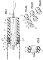
- Figure 1 there is shown the coaxial mounting of the metal support cylinder 10, the intermediate sleeve 12, the thin sleeve 14 on which we have shown under the reference 16, either a rubber lining engraved with the image 18, or an actual photograph with the same image, according to the choice of the user and the needs dictated by the type of image.
- the central nozzle 20 for introducing compressed air is generally formed coaxially with one of the axes of the metal support cylinder.
- the support cylinder is made of metal and the intermediate sleeve as well as the thin sleeve are made of polymer material.
- the intermediate sleeve is produced according to the teaching of French patent application No. 94 06417.
- the metal support cylinder 10 comprises nozzles 22 distributed regularly, along a through circle, at the periphery of said cylinder in order to put the interior of this cylinder into communication with the outside, the air path 24 being symbolized by arrows 26.
- the intermediate sleeve 12 comprises a ring 28 fixed in rotation relative to the body of the intermediate sleeve and a movable ring 29, free to rotate on the fixed ring 28.
- the fixed ring has an outside diameter equal to that of the outside diameter of the sleeve, and an internal diameter equal to the diameter of a projection 30 formed at the end of the intermediate body.
- This fixed ring has a reduced diameter over a part of its length, equal, apart from play, to the inside diameter of the movable ring.
- the movable ring 29 has an outside diameter equal to the outside diameter of the body of the intermediate sleeve and to the outside diameter of the fixed ring in its non-reduced diameter portion.
- Nozzles 34, 36 are machined respectively through the thickness of the reduced diameter portion of the fixed ring 28 and through the thickness of the movable ring 29.
- the sleeve body also carries nozzles 38 in the part located to the right of the projection.
- this intermediate sleeve is carried out according to steps 2A to 2C.
- the movable ring 29 is threaded onto the reduced diameter part of the fixed ring 28 and then the fixed ring is mounted with its movable ring coaxially with the projection 30 of the corsp of the intermediate cylinder by interposing a fixing means such as a cyanoacrylate type adhesive sold under the name "loctite" taking the precaution of making the nozzles 34 of the fixed ring coincide with the nozzles 38 of the projection 30 of the intermediate sleeve.
- the movable ring 29 can rotate relative to the reduced diameter portion of the fixed ring while this same fixed ring is immobilized in translation, thus retaining the mobile ring.
- FIG. 3A it can be seen that the nozzles 22, 34, 36 and 38 are distributed along identical angular sectors so that in a given position, they can be aligned.
- the assembly of such an assembly is carried out by introducing pressurized air through the nozzle 20 which passes through the nozzles 22 of the support cylinder 10.
- the operator threads the intermediate sleeve 12 through the end of the cylinder provided with these nozzles 22.
- the air film allows easy insertion of this intermediate sleeve.
- the ring 29 is in the position shown in FIG. 3B, that is to say a position in which the nozzles 36 and 38 are in coincidence by manufacture but in which the nozzles 34 are not in coincidence with the nozzles 36 and 38.
- the intermediate sleeve once inserted as far as possible and correctly positioned on the metal support cylinder, is locked on this support cylinder by rotation of the movable ring 29 in order to bring the nozzles 36 and 38 in coincidence with the nozzles 34, c ' that is to say in the position of FIG. 3A.
- the thin sleeve 14 is then threaded in turn on the intermediate sleeve 12, because the air which escapes through the four series of nozzles forms an air film which allows a very easy assembly.
- the operator can then mount a new thin sleeve.
- the intermediate sleeve is removed by rotation of the ring and the operator mounts, after removal of the sleeve used, the new sleeve.
- the metal support cylinder should also be changed.
- FIG 4 there is shown a variant of the intermediate sleeve in which the ring has been removed and replaced by threaded cylindrical inserts 40 in which threaded plugs 42 can be screwed.
- Threaded plugs play the same role as the ring and if they are a little less flexible to use, their cost is lower.
- the ring is formed in a projection machined from the inner periphery of the intermediate sleeve, but such a projection can be formed from the outer periphery.
- positioning indexes can be displayed to facilitate assembly and prior adjustment operations.
- the intermediate sleeves are produced according to the teaching of patent application FR-A-94 06417.
- Each sleeve comprises a succession of layers of honeycomb material preferably embedded in a resin matrix.
- the manufacturing support is a metal cylinder rectified to the diameter of the subsequent support cylinder.
- the peripheral inner surface has a polished appearance.
- the outer surface is ground to the exact diameter allowing tight fitting of the thin sleeve.
- composition of the resin is adapted to give the sleeve a calculated shrinkage which ensures a tight fitting radially.
- a known mechanical machining is provided and within the reach of those skilled in the art.
Landscapes
- Manufacture Or Reproduction Of Printing Formes (AREA)
- Rotary Presses (AREA)
- Printing Plates And Materials Therefor (AREA)
- Rolls And Other Rotary Bodies (AREA)
- Discharging, Photosensitive Material Shape In Electrophotography (AREA)
- Delivering By Means Of Belts And Rollers (AREA)
- Rollers For Roller Conveyors For Transfer (AREA)
Abstract
Description
La présente invention a pour objet un manchon intercalaire porte-manchon pour machine notamment flexographique et l'agencement d'un cylindre d'impression complet.The subject of the present invention is an intermediate sleeve-sleeve holder for a flexographic machine in particular and the arrangement of a complete printing cylinder.
Les machines d'impression flexographique comprennent plusieurs groupes d'impressions successifs en fonction du nombre de couleurs, chaque groupe ayant pour rôle d'imprimer, dans la couleur donnée qui lui a été attribuée, une image en sorte d'obtenir la représentation graphique en couleurs telle que désirée.Flexographic printing machines include several successive groups of prints depending on the number of colors, each group having the role of printing, in the given color which has been assigned to it, an image so as to obtain the graphic representation in colors as desired.
De telles machines ont des capacités d'impression très importantes si bien qu'elles produisent à de grandes cadences des images d'une grande qualité graphique. Aussi, les opérateurs sont amenés très régulièrement à changer les cylindres portant les clichés.Such machines have very large printing capacities so that they produce images of high graphic quality at high rates. Also, the operators are brought very regularly to change the cylinders carrying the stereotypes.
De façon à gagner du temps et de l'argent, les images sont portées par des manchons porte-cliché ou des manchons garnis caoutchouc qui sont directement gravés au laser dans l'épaisseur du garnissage.In order to save time and money, the images are carried by cliché sleeves or rubber-lined sleeves which are directly lasered in the thickness of the lining.
Ainsi, il est possible de gagner un temps précieux pour effectuer des changements de production ; les clichés sont préparés, c'est-à-dire montés et calés puis fixés sur le manchon, ensuite les manchons porte-cliché ou gravés sont montés sur des cylindres supplémentaires pendant qu'un premier jeu est en place et fonctionne sur la machine.Thus, it is possible to save precious time to make production changes; the plates are prepared, that is to say mounted and wedged and then fixed on the sleeve, then the plate or engraved sleeves are mounted on additional cylinders while a first set is in place and operating on the machine.
Lors du changement, les cylindres et leurs manchons sont retirés de la machine tandis que le jeu de cylindres et de manchons en attente sont alors mis en place sur la machine.When changing, the cylinders and their sleeves are removed from the machine while the set of waiting cylinders and sleeves are then placed on the machine.
Il reste ensuite à caler la machine, c'est-à-dire à caler le déplacement de la bande à imprimer d'un groupe à l'autre pour qu'il y ait une superposition des impressions dans chacune des couleurs. On comprend, s'il s'agit d'une image différente mais avec un même développement, qu'il faille deux jeux de cylindres supports en métal.It then remains to wedge the machine, that is to say to wedge the displacement of the strip to be printed from one group to another so that there is a superposition of the prints in each of the colors. We understand, if it is a different image but with the same development, that it takes two sets of metal support cylinders.
Ainsi, le parc doit être doublé, faute de quoi, il faut arrêter la machine, retirer les clichés utilisés, positionner les nouveaux sur les manchons, ce qui est impossible du point de vue de la rentabilité.Thus, the fleet must be doubled, otherwise, the machine must be stopped, the clichés used must be removed, the new ones must be positioned on the sleeves, which is impossible from the point of view of profitability.
Une telle opération est ainsi un net progrès.Such an operation is thus a clear progress.
Ainsi, on constate que l'investissement dans des jeux de cylindres en double est déjà une solution intéressante, mais qui reste encore très coûteuse.Thus, it can be seen that investing in sets of duplicate cylinders is already an attractive solution, but one which is still very expensive.
Néanmoins, les manchons porte-cliché ou garnis ont une faible épaisseur et il faut un nombre de cylindres supports très important pour couvrir la gamme de développements nécessaires. Les cylindres en métal rectifié coûtent cher et l'investissement du parc cylindres d'une machine flexographique est très élevé, ceci d'autant plus qu'il y a de couleurs.However, the cliché or trim sleeves have a small thickness and a very large number of support cylinders is required to cover the range of developments required. Rectified metal cylinders are expensive and the investment of the cylinder fleet of a flexographic machine is very high, especially since there are colors.
Une première solution pour diminuer le parc a été proposée par les Demandeurs dans la demande de brevet français N° 94 06417 qui consiste à réaliser des manchons de forte épaisseur en matériau adapté pour présenter une dureté suffisante, des qualités de tenue dans le temps parfaites et être aptes à la rectification lorsqu'ils doivent supporter des clichés collés ou êtres aptes à l'accrochage d'un garnissage en caoutchouc pour un gravage laser ultérieur.A first solution to reduce the fleet has been proposed by the Applicants in French patent application No. 94 06417 which consists in making sleeves of very thick material suitable for having sufficient hardness, qualities of resistance over time perfect and be suitable for rectification when they have to support glued plates or be suitable for attaching a rubber lining for later laser engraving.
Cette solution très attractive permet de diminuer l'investissement en cylindres supports en métal car les manchons de forte épaisseur en matériau composite sont moins chers. De plus, ils sont beaucoup plus aisés à manipuler grâce à un poids très inférieur à celui des cylindres en métal.This very attractive solution makes it possible to reduce the investment in metal support cylinders because the thick sleeves made of composite material are less expensive. In addition, they are much easier to handle thanks to a much lower weight than that of metal cylinders.
Pour des laizes de type courant, un manchon en matériau composite peut être porté par une seule personne, sans enfreindre les lois du travail, ceci quel que soit le diamètre, dans la gamme courante. Ceci évite toutes les manutentions au palan avec tous les inconvénients qui y sont attachés. De ce fait, il devient non seulement inutile de disposer d'un jeu de cylindres supports en métal couvrant chaque développement et les développements immédiatement supérieurs mais on supprime de plus le second jeu de cylindres dans le même développement.For standard widths, a sleeve made of composite material can be worn by one person, without break labor laws, regardless of diameter, in the current range. This avoids all handling with the hoist with all the drawbacks attached to it. As a result, it not only becomes unnecessary to have a set of metal support cylinders covering each development and the immediately higher developments, but the second set of cylinders in the same development is also eliminated.
Il suffit donc de constituer un parc réduit de cylindres supports en métal avec des écarts d'une ou plusieurs dizaines de développements et d'investir dans des manchons avec un même diamètre intérieur, mais couvrant les développements intermédiaires, avec un nombre doublé si l'on souhaite préparer les clichés préalablement lorsque le développement de remplacement est identique au développement en cours.It therefore suffices to constitute a reduced fleet of metal support cylinders with deviations of one or more tens of developments and to invest in sleeves with the same internal diameter, but covering intermediate developments, with a number doubled if the we want to prepare the shots beforehand when the replacement development is identical to the development in progress.
Bien sûr, si les développements sont différents mais que le diamètre intérieur du manchon est identique, c'est-à-dire que le développement est situé dans l'intervalle de développement compris entre deux jeux de cylindres supports en métal consécutifs, on comprend tout l'intérêt de ces manchons de forte épaisseur ; il est en effet possible de laisser en place les cylindres supports en métal, de retirer les manchons utilisés et de monter les nouveaux manchons préalablement préparés. Le temps d'immobilisation de la machine est réduit à son minimum.Of course, if the developments are different but the inside diameter of the sleeve is identical, that is to say that the development is located in the development interval between two sets of consecutive metal support cylinders, we understand everything the advantage of these thick sleeves; it is indeed possible to leave the metal support cylinders in place, remove the sleeves used and mount the new sleeves previously prepared. The machine downtime is reduced to a minimum.
En effet, l'opération du changement de manchons est rendue très facile grâce à l'utilisation de cylindres supports à l'intérieur desquels on introduit de l'air sous pression qui est évacué par des ajutages répartis sur la périphérie du cylindre le long d'un cercle dans une zone située à proximité immédiate de l'extrémité du cylindre support par laquelle on introduit ou on retire ledit manchon.Indeed, the operation of changing sleeves is made very easy thanks to the use of support cylinders inside which air is introduced under pressure which is evacuated by nozzles distributed over the periphery of the cylinder along d 'a circle in an area located in the immediate vicinity of the end of the support cylinder by which said sleeve is inserted or removed.
L'air, sous une pression de quelques bars, forme un matelas d'air entre la surface externe du cylindre support en métal et le manchon, dilatant très faiblement ce dernier mais de façon suffisante pour qu'il coulisse aisément en translation sur ledit cylindre support. Dès que l'introduction d'air sous pression à l'intérieur du cylindre est interrompue, le manchon se plaque sous l'effet de sa propre élasticité sur le cylindre support. On a pu constater que l'effort de serrage radial sur toute la surface assure une immobilisation parfaite du manchon sur le cylindre support, en tous cas, tout à fait suffisante pour l'application concernée.The air, under a pressure of a few bars, forms an air mattress between the external surface of the metal support cylinder and the sleeve, expanding the latter very slightly but sufficiently so that it slides easily in translation on said cylinder support. As soon as the introduction of pressurized air inside the cylinder is interrupted, the sleeve is pressed under the effect of its own elasticity on the support cylinder. We could see that the radial clamping force over the entire surface ensures perfect immobilization of the sleeve on the support cylinder, in any case, quite sufficient for the application concerned.
Si une telle solution des manchons de forte épaisseur est un progrès considérable par rapport aux solutions de l'art antérieur par diminution du parc de cylindres supports en métal, par une grande facilité de manutention, par des gains de temps très substantiels au montage, par la facilité de dépose et repose sur les cylindres supports, il n'en demeure pas moins qu'il faut disposer, dans le cas d'un même développement, de deux jeux de manchons. Le surcoût est proportionnel également à l'épaisseur même si cette proportionnalité n'est pas linéaire.If such a solution of thick sleeves is a considerable improvement over the solutions of the prior art by reducing the number of metal support cylinders, by great ease of handling, by very substantial time savings during assembly, by ease of removal and rests on the support cylinders, the fact remains that it is necessary in the case of the same development, two sets of sleeves. The additional cost is also proportional to the thickness even if this proportionality is not linear.
La présente invention a donc pour objet de proposer des manchons intercalaires qui solutionnent ce problème de la double série dans un même développement et qui, de façon plus générale, permettent de recourir à des manchons porte-cliché ou garnis et gravés laser de faible épaisseur, ceci pour tous les développements, tout en requérant un parc réduit de cylindres supports en métal. Les manchons minces sont renouvelés pour chaque cliché car ils ne peuvent être rechargés en caoutchouc, ou ils risquent d'être endommagés lors de la dépose du cliché.The object of the present invention is therefore to propose intermediate sleeves which solve this problem of the double series in the same development and which, more generally, make it possible to use sleeves for cliché or trimmed and laser engraved of small thickness, this for all developments, while requiring a reduced fleet of metal support cylinders. The thin sleeves are renewed for each plate because they cannot be refilled with rubber, or they may be damaged when the plate is removed.
A cet effet, la présente invention a pour objet un agencement d'un cylindre complet d'imprimerie flexographique, comprenant un cylindre support creux d'un diamètre donné, prévu pour être entraîné en rotation et équipé d'une alimentation interne d'air comprimé avec des ajutages traversants, ménagés suivant une répartition angulaire donnée, en périphérie sensiblement le long d'un cercle à proximité immédiate de l'extrémité d'introduction, et qui se caractérise en ce qu'il comprend au moins un manchon intercalaire d'un diamètre intérieur compatible avec le diamètre extérieur du cylindre support pour un montage serré radialement, et un diamètre extérieur compatible avec le diamètre d'un manchon mince portant l'image pour un montage serré radialement dont le diamètre extérieur est égal à celui du développement recherché, ledit manchon intercalaire comprenant des ajutages sensiblement le long d'un cercle, ayant la même répartition angulaire que celle du cylindre support et des moyens d'obturation de ces ajutages de façon à permettre le montage de ce manchon intercalaire sur le cylindre support.To this end, the subject of the present invention is an arrangement of a complete cylinder for flexographic printing, comprising a hollow support cylinder of a given diameter, intended to be driven in rotation and equipped with an internal supply of compressed air. with through nozzles, arranged according to a given angular distribution, at the periphery substantially along a circle in the immediate vicinity of the insertion end, and which is characterized in that it comprises at least one intermediate sleeve of a internal diameter compatible with the external diameter of the support cylinder for a radially tight mounting, and an external diameter compatible with the diameter of a thin sleeve bearing the image for a radially tight mounting whose external diameter is equal to that of the desired development, said intermediate sleeve comprising nozzles substantially along a circle, having the same angular distribution as that of the support cylinder and means for closing off these nozzles so as to allow the mounting of this intermediate sleeve on the support cylinder.
Selon un mode préférentiel de réalisation, les moyens d'obturation comprennent une bague montée fixe en translation, notamment grâce à une bague fixe, suivant l'axe longitudinal du manchon intercalaire et mobile en rotation entre deux positions, ouverte et fermée, dans un ressaut ménagé au droit des ajutages du manchon intercalaire, ladite bague étant elle-même munie d'ajutages ayant la même répartition angulaire que celle des ajutages du cylindre support et du manchon intercalaire avec la position ouverte correspondant à la coïncidence des ajutages du manchon intercalaire avec les ajutages de la bague et une position fermée dans laquelle les ajutages de la bague sont décalés par rapport à ceux du manchon.According to a preferred embodiment, the sealing means comprise a ring mounted fixed in translation, in particular by means of a fixed ring, along the longitudinal axis of the intermediate sleeve and movable in rotation between two positions, open and closed, in a projection formed in line with the nozzles of the intermediate sleeve, said ring itself being provided with nozzles having the same angular distribution as that of the nozzles of the support cylinder and of the intermediate sleeve with the open position corresponding to the coincidence of the nozzles of the intermediate sleeve with the ring nozzles and a closed position in which the ring nozzles are offset from those of the sleeve.
Selon ce mode de réalisation, la bague comprend des joints d'étanchéité, de façon à éviter les fuites d'air comprimé entre la bague et le manchon et la bague est montée dans un ressaut ménagé à partir de la périphérie intérieure.According to this embodiment, the ring comprises seals, so as to avoid the leakage of compressed air between the ring and the sleeve and the ring is mounted in a projection formed from the inner periphery.
Selon une variante de réalisation, les moyens d'obturation comprennent des inserts fixes creux traversant l'épaisseur du manchon intercalaire, lesdits inserts ayant une répartition angulaire identique à celle des ajutages du cylindre support, lesdits inserts étant taraudés pour recevoir des bouchons filetés amovibles.According to an alternative embodiment, the closure means comprise hollow fixed inserts passing through the thickness of the intermediate sleeve, said inserts having an angular distribution identical to that of the nozzles of the support cylinder, said inserts being tapped to receive removable threaded plugs.
Dans le cas de plusieurs manchons intercalaires coaxiaux, ces manchons comprennent des index de façon à permettre l'alignement des différents ajutages suivant des directions radiales.In the case of several coaxial intermediate sleeves, these sleeves include indexes so as to allow the alignment of the different nozzles in radial directions.
L'invention a également pour objet le manchon intercalaire pour la mise en oeuvre de l'agencement indiqué ci-avant.The invention also relates to the intermediate sleeve for the implementation of the arrangement indicated above.
Les avantages liés aux manchons intercalaires sont d'ordre pratique car, d'une part, le stockage est réduit et, d'autre part, les "voyages" de manchons de forte épaisseur à regarnir et à graver sont supprimés. Ceci influe sur les coûts des investissements et sur les coûts de production tant par la réduction des frais de stockage, de gestion mais aussi de manutention et surtout par une nouvelle réduction du temps d'immobilisation machine.The advantages linked to the intermediate sleeves are practical because, on the one hand, the storage is reduced and, on the other hand, the "journeys" of sleeves of great thickness to be relined and engraved are eliminated. This influences investment costs and production costs both by reducing storage and management costs, but also handling and above all by further reducing machine downtime.
La présente invention est décrite ci-après selon un mode de réalisation particulier avec des variantes, ceci en regard des dessins annexés qui représentent sur :
- la figure 1, une vue schématique en perspective d'un ensemble cylindre support en métal, manchon intercalaire et manchon mince,
- la figure 2, une vue en coupe longitudinale d'un mode de réalisation préférentiel de l'invention,
- les figures 2A, 2B, 2C montrent des vues éclatées du montage de la bague du manchon de la figure 2,
- la figure 3A une vue en section transversale, suivant la ligne 3-3, de l'ensemble de la figure 2, dans la position pose ou dépose du manchon mince sur le manchon intercalaire,
- la figure 3B, une vue en section transversale dans la position pose ou dépose du manchon intercalaire, et
- la figure 4, une vue en coupe longitudinale d'une variante de réalisation du manchon intercalaire.
- FIG. 1, a schematic perspective view of a metal support cylinder, intermediate sleeve and thin sleeve assembly,
- FIG. 2, a view in longitudinal section of a preferred embodiment of the invention,
- FIGS. 2A, 2B, 2C show exploded views of the mounting of the ring of the sleeve of FIG. 2,
- FIG. 3A is a cross-sectional view, along line 3-3, of the assembly of FIG. 2, in the position of placing or removing the thin sleeve on the intermediate sleeve,
- FIG. 3B, a cross-sectional view in the position of placing or removing the intermediate sleeve, and
- Figure 4, a longitudinal sectional view of an alternative embodiment of the intermediate sleeve.
Sur la figure 1, on a représenté le montage coaxial du cylindre support en métal 10, du manchon intercalaire 12, du manchon mince 14 sur lequel on a fait apparaître sous la référence 16, soit un garnissage caoutchouc gravé avec l'image 18, soit un cliché proprement dit avec la même image, suivant le choix de l'utilisateur et les besoins dictés par le type d'image.In Figure 1, there is shown the coaxial mounting of the
Le piquage central 20 d'introduction d'air comprimé est généralement ménagé coaxialement à l'un des axes du cylindre support en métal.The
Les références identiques sont portées sur la figure 2. Le cylindre support est en métal et le manchon intercalaire tout comme le manchon mince sont réalisés en matériau polymère.Identical references are given in FIG. 2. The support cylinder is made of metal and the intermediate sleeve as well as the thin sleeve are made of polymer material.
Avantageusement, le manchon intercalaire est réalisé selon l'enseignement de la demande de brevet français N° 94 06417.Advantageously, the intermediate sleeve is produced according to the teaching of French patent application No. 94 06417.
Le cylindre support 10 en métal comprend des ajutages 22 répartis régulièrement, le long d'un cercle débouchant, à la périphérie dudit cylindre afin de mettre en communication l'intérieur de ce cylindre avec l'extérieur, le trajet de l'air 24 étant symbolisé par des flèches 26.The
Le manchon intermédiaire 12 comprend une bague 28 fixe en rotation par rapport au corps du manchon intermédiaire et une bague mobile 29, libre en rotation sur la bague fixe 28. La bague fixe a un diamètre extérieur égal à celui du diamètre extérieur du manchon, et un diamètre intérieur égal au diamètre d'un ressaut 30 ménagé à l'extrémité du corps intermédiaire.The
Cette bague fixe a un diamètre réduit sur une partie de sa longueur, égal, au jeu près, au diamètre intérieur de la bague mobile.This fixed ring has a reduced diameter over a part of its length, equal, apart from play, to the inside diameter of the movable ring.
La bague mobile 29 a un diamètre extérieur égal au diamètre extérieur du corps du manchon intermédiaire et au diamètre extérieur de la bague fixe dans sa partie à diamètre non réduit.The
Des ajutages 34, 36 sont usinés respectivement à travers l'épaisseur de la partie à diamètre réduit de la bague fixe 28 et à travers l'épaisseur de la bague mobile 29.
Le corps du manchon porte également des ajutages 38 dans la partie située au droit du ressaut.The sleeve body also carries
Le montage de ce manchon intercalaire s'effectue suivant les étapes 2A à 2C. On enfile la bague mobile 29 sur la partie à diamètre réduit de la bague fixe 28 puis on monte la bague fixe avec sa bague mobile coaxialement au ressaut 30 du corsp du cylindre intermédiaire en interposant un moyen de fixation tel qu'une colle de type cyanoacrylate vendue sous le dénomination "loctite" en prenant la précaution de faire coïncider les ajutages 34 de la bague fixe avec les ajutages 38 du ressaut 30 du manchon intermédiaire.The mounting of this intermediate sleeve is carried out according to steps 2A to 2C. The
Ainsi, la bague mobile 29 peut tourner par rapport à la partie à diamètre réduit de la bague fixe tandis que cette même bague fixe est immobilisée en translation retenant ainsi la bague mobile.Thus, the
Sur la figure 3A, on constate que les ajutages 22, 34, 36 et 38 sont répartis suivant des secteurs angulaires identiques de façon que dans une position donnée, ils puissent être alignés.In FIG. 3A, it can be seen that the
Le montage d'un tel ensemble s'effectue en introduisant de l'air sous pression par le piquage 20 qui passe à travers les ajutages 22 du cylindre support 10.The assembly of such an assembly is carried out by introducing pressurized air through the
L'opérateur enfile le manchon intermédiaire 12 par l'extrémité du cylindre munie de ces ajutages 22. Le film d'air permet une introduction aisée de ce manchon intercalaire.The operator threads the
La bague 29 est dans la position représentée sur la figure 3B, c'est-à-dire une position dans laquelle les ajutages 36 et 38 sont en coïncidence par fabrication mais dans laquelle les ajutages 34 ne sont pas en coïncidence avec les ajutages 36 et 38.The
Le manchon intercalaire, une fois enfilé au maximum et correctement positionné sur le cylindre support en métal, est bloqué sur ce cylindre support par rotation de la bague mobile 29 afin d'amener les ajutages 36 et 38 en coïncidence avec les ajutages 34, c'est-à-dire dans la position de la figure 3A.The intermediate sleeve, once inserted as far as possible and correctly positioned on the metal support cylinder, is locked on this support cylinder by rotation of the
Le manchon mince 14 est alors enfilé à son tour sur le manchon intercalaire 12, car l'air qui s'échappe à travers les quatre séries d'ajutages forme un film d'air qui autorise un montage tout à fait aisé.The
Une fois ce manchon mince correctement positionné, l'opérateur coupe l'alimentation en air comprimé, ce qui a pour effet immédiat de bloquer le manchon mince sur le manchon intercalaire, lui-même solidarisé sur le cylindre support en métal.Once this thin sleeve is correctly positioned, the operator cuts off the supply of compressed air, which has the immediate effect of blocking the thin sleeve on the intermediate sleeve, itself secured to the metal support cylinder.
Pour la dépose, il suffit de procéder aux opérations ci-dessus dans l'ordre inverse.For removal, simply carry out the above operations in reverse order.
Si le développement est identique, on remarque qu'il suffit d'alimenter l'ensemble en air comprimé, de retirer le manchon mince sans toucher à la bague, de façon que le manchon intercalaire reste en place.If the development is identical, we note that it suffices to supply the assembly with compressed air, to remove the thin sleeve without touching the ring, so that the intermediate sleeve remains in place.
L'opérateur peut ensuite monter un nouveau manchon mince.The operator can then mount a new thin sleeve.
Dans le cas où il faut changer de développement, on retire le manchon intercalaire par rotation de la bague et l'opérateur monte, après retrait du manchon utilisé, le nouveau manchon.In the case where it is necessary to change development, the intermediate sleeve is removed by rotation of the ring and the operator mounts, after removal of the sleeve used, the new sleeve.
Si le développement est grandement différent du diamètre du cylindre support en métal, et ne peut être couvert par un manchon intercalaire, il convient de procéder également au changement du cylindre support en métal.If the development is very different from the diameter of the metal support cylinder, and cannot be covered by an intermediate sleeve, the metal support cylinder should also be changed.
Sur la figure 4, on a représenté une variante du manchon intercalaire dans laquelle la bague a été supprimée et remplacée par des inserts cylindriques taraudés 40 dans lesquels des bouchons filetés 42 peuvent se visser.In Figure 4, there is shown a variant of the intermediate sleeve in which the ring has been removed and replaced by threaded
Les bouchons filetés jouent le même rôle que la bague et s'ils sont un peu moins souple d'utilisation, leur prix de revient est moins élevé.Threaded plugs play the same role as the ring and if they are a little less flexible to use, their cost is lower.
On peut imaginer, avec les seules connaissances de l'homme de l'art, d'autres solutions pour laisser passer l'air ou obturer le passage prévu à cet effet, sans sortir du cadre de l'invention.One can imagine, with the knowledge of those skilled in the art alone, other solutions for letting the air pass or closing the passage provided for this purpose, without departing from the scope of the invention.
On peut également donner un exemple chiffré qui, même s'il ne donne pas nécessairement des montants exacts en valeur absolue, représente néanmoins l'échelle et les rapports.We can also give a numerical example which, even if it does not necessarily give exact amounts in absolute value, nevertheless represents the scale and the relationships.
Un imprimeur souhaite honorer une commande de 10 modèles d'impression différents en quatre couleurs, avec un même développement d'impression, par exemple 820 mm. Cet imprimeur ne possède qu'un ensemble de cylindres supports en métal de 680 mm, soit quinze développements inférieurs à celui de la commande. Il y a donc 40 clichés gravés et 10 changements en machine il a alors l'opportunité de faire les solutions suivantes.
- PREMIERE SOLUTION :
- Achat de 4 cylindres supports en métal de 820 mm.
- Pour une laize donnée, le prix est de :

- INCONVENIENT :
- L'imprimeur doit arrêter sa machine après chaque tirage, retirer les cylindres, retirer les clichés de ces cylindres, repositionner les nouveaux clichés du tirage suivant. Arrêt de 5 heures à 6 heures suivant la dextérité des opérateurs.
- Au coût horaire d'une machine 4 couleurs, la perte est de :

- Il vaut donc mieux, ainsi que cela a été mentionné dans le préambule, prévoir l'investissement de deux jeux de cylindres, soit 56.000 F.
- DEUXIEME SOLUTION :
- Achat de deux jeux de manchons composites de forte épaisseur (22 mm) au prix de 3.200 F.

- Il y a alors un gain sur l'investissement par rapport à la solution métal car la manutention est aisée. De plus, les cylindres supports en métal restent sur la machine, il suffit de déposer et reposer les manchons sur les cylindres, ce qui procure un gain de temps à nouveau important.
- Un problème se pose lorsque les manchons épais sont directement garnis en caoutchouc car la présente opération de 10 tirages successifs différents oblige à avoir tous les manchons épais prêts et ceci pour chaque tirage.
- Cette solution présente tout son intérêt mais essentiellement pour les manchons porte-cliché.
- Achat de deux jeux de manchons composites de forte épaisseur (22 mm) au prix de 3.200 F.
- TROISIEME SOLUTION :
- Achat de 4 manchons intercalaires de 21 mm d'épaisseur et de 20 manchons minces porte-clichés ou garnis, soit :

- Cette solution permet de rentabiliser au mieux la machine en optimisant les changements qui ne prennent plus que quelques minutes, si bien que l'arrêt machine peut être quasiment négligé et cette fois-ci quelle que soit la technique retenue, manchon mince porte-cliché ou garni et gravé. De plus, la manutention est encore diminuée puisque les manchons minces sont d'un poids très faible et le positionnement est également très aisé.
- On constate que pour un investissement du même ordre que pour la deuxième solution, seul le manchon intercalaire permet de gagner en coût d'immobilisation machine, en temps et qualité de pose et dépose, quel que soit le mode de cliché imprimant retenu.
- On remarque également que la présence d'un manchon intercalaire permet de jouer sur le garnissage du manchon mince pour traiter les développements très voisins également. Il n'est mentionné que les développements très voisins car le caoutchouc est cher, lourd et, de plus, la qualité d'impression serait altérée par une épaisseur trop importante.
- Achat de 4 manchons intercalaires de 21 mm d'épaisseur et de 20 manchons minces porte-clichés ou garnis, soit :
- FIRST SOLUTION :
- Purchase of 4 820 mm metal support cylinders.
- For a given width, the price is:
- DISADVANTAGE :
- The printer must stop his machine after each print, remove the cylinders, remove the photos from these cylinders, reposition the new photos from the next print. Stop from 5 hours to 6 hours depending on the operators' dexterity.
- At the hourly cost of a 4-color machine, the loss is:
- It is therefore better, as mentioned in the preamble, to plan the investment of two sets of cylinders, that is 56,000 F.
- SECOND SOLUTION :
- Purchase of two sets of thick composite sleeves (22 mm) at a price of 3,200 F.
- There is then a gain on the investment compared to the metal solution because the handling is easy. In addition, the metal support cylinders remain on the machine, it suffices to deposit and rest the sleeves on the cylinders, which again saves time.
- A problem arises when the thick sleeves are directly lined with rubber because the present operation of 10 different successive prints obliges to have all the thick sleeves ready and this for each draw.
- This solution is of great interest, but mainly for plate-holding sleeves.
- Purchase of two sets of thick composite sleeves (22 mm) at a price of 3,200 F.
- THIRD SOLUTION :
- Purchase of 4 intermediate sleeves, 21 mm thick and 20 thin sleeves for plate or trim, either:
- This solution makes it possible to make the machine profitable as much as possible by optimizing the changes which only take a few minutes, so that the machine stop can be almost neglected and this time whatever the technique chosen, thin sleeve cliché holder or trimmed and engraved. In addition, handling is further reduced since the thin sleeves are very light and positioning is also very easy.
- It is noted that for an investment of the same order as for the second solution, only the intermediate sleeve makes it possible to save in machine immobilization cost, in time and quality of installation and removal, whatever the mode of printing cliché adopted.
- It is also noted that the presence of an intermediate sleeve makes it possible to play on the lining of the thin sleeve to treat very similar developments as well. Only very similar developments are mentioned because the rubber is expensive, heavy and, moreover, the print quality would be impaired by an excessively large thickness.
- Purchase of 4 intermediate sleeves, 21 mm thick and 20 thin sleeves for plate or trim, either:
Par contre, on peut envisager, compte tenu des qualités notamment mécaniques des manchons intercalaires en matériau composite, du prix et du poids, de disposer plusieurs manchons intercalaires montés coaxialement. On comprend dès lors qu'avec un jeu de cylindres supports en métal et quelques jeux de manchons intercalaires et en jouant sur l'épaisseur du garnissage des manchons minces, on couvre une gamme de développements très importante.On the other hand, it is possible to envisage, taking into account the notably mechanical qualities of the intermediate sleeves made of composite material, the price and the weight, to have several intermediate sleeves mounted coaxially. It is therefore understandable that with a set of metal support cylinders and a few sets of intermediate sleeves and by varying the thickness of the lining of the thin sleeves, a very large range of developments is covered.
Cet agencement est d'un grand intérêt pour ce domaine d'activité que constitue l'impression flexographique. Selon un mode de réalisation tel que représenté, la bague est ménagée dans un ressaut usiné à partir de la périphérie intérieure du manchon intercalaire mais un tel ressaut peut être ménagé à partir de la périphérie extérieure.This arrangement is of great interest for this field of activity that constitutes flexographic printing. According to an embodiment as shown, the ring is formed in a projection machined from the inner periphery of the intermediate sleeve, but such a projection can be formed from the outer periphery.
De façon perfectionnée, on peut faire apparaître des index de positionnement pour faciliter les opérations de montage et de réglage préalable.In an improved manner, positioning indexes can be displayed to facilitate assembly and prior adjustment operations.
Les manchons intercalaires sont réalisés suivant l'enseignement de la demande de brevet FR-A-94 06417.The intermediate sleeves are produced according to the teaching of patent application FR-A-94 06417.
Chaque manchon comprend une succession de couches de matériau en nid d'abeille de préférence noyées dans une matrice en résine. Le support de fabrication est un cylindre en métal rectifié au diamètre du cylindre support ultérieur.Each sleeve comprises a succession of layers of honeycomb material preferably embedded in a resin matrix. The manufacturing support is a metal cylinder rectified to the diameter of the subsequent support cylinder.
Ainsi, la surface intérieure périphérique est d'aspect poli.Thus, the peripheral inner surface has a polished appearance.
La surface extérieure est rectifiée au diamètre exact permettant le montage serré du manchon mince.The outer surface is ground to the exact diameter allowing tight fitting of the thin sleeve.
La composition de la résine est adaptée pour conférer au manchon un retrait calculé qui assure un montage serré radialement. Dans le cas du montage d'une bague, il est prévu un usinage mécanique connu et à la portée de l'homme de l'art.The composition of the resin is adapted to give the sleeve a calculated shrinkage which ensures a tight fitting radially. In the case of mounting a ring, a known mechanical machining is provided and within the reach of those skilled in the art.
Dans le cas du montage avec inserts, ceux-ci sont noyés préalablement dans les couches lors de la fabrication, à une profondeur suffisante pour permettre la rectification finale du manchon intercalaire.In the case of assembly with inserts, these are previously embedded in the layers during manufacture, to a depth sufficient to allow the final rectification of the intermediate sleeve.
Claims (9)
Applications Claiming Priority (2)
| Application Number | Priority Date | Filing Date | Title |
|---|---|---|---|
| FR9413801 | 1994-11-14 | ||
| FR9413801A FR2726786A1 (en) | 1994-11-14 | 1994-11-14 | ARRANGEMENT AND INTERMEDIATE SLEEVE THIN SLEEVE HOLDER IN PARTICULAR FOR FLEXOGRAPHIC PRINTING MACHINE |
Publications (2)
| Publication Number | Publication Date |
|---|---|
| EP0711665A1 true EP0711665A1 (en) | 1996-05-15 |
| EP0711665B1 EP0711665B1 (en) | 1999-03-10 |
Family
ID=9468909
Family Applications (1)
| Application Number | Title | Priority Date | Filing Date |
|---|---|---|---|
| EP95450016A Expired - Lifetime EP0711665B1 (en) | 1994-11-14 | 1995-11-13 | Sleeve arrangement and intermediate sleeve for carrying a thin sleeve, in particular for a flexographic printing machine |
Country Status (9)
| Country | Link |
|---|---|
| US (1) | US5706731A (en) |
| EP (1) | EP0711665B1 (en) |
| JP (1) | JPH08207235A (en) |
| AT (1) | ATE177366T1 (en) |
| CA (1) | CA2162657A1 (en) |
| DE (1) | DE69508184T2 (en) |
| DK (1) | DK0711665T3 (en) |
| ES (1) | ES2131786T3 (en) |
| FR (1) | FR2726786A1 (en) |
Cited By (9)
| Publication number | Priority date | Publication date | Assignee | Title |
|---|---|---|---|---|
| EP0753416A1 (en) * | 1995-07-10 | 1997-01-15 | POLYWEST KUNSTSTOFFTECHNIK Saueressig & Partner GmbH & Co. KG | Process for the fabrication of a seamless printing sleeve, in particular for a flexographic printing cylinder |
| FR2785226A1 (en) * | 1998-11-02 | 2000-05-05 | Polyfibron Technologies Sa | Printing cylinder for offset printer includes transverse channels with non-return valves linking inner support cylinder to outer removable cylinder |
| US6283026B1 (en) | 1998-11-02 | 2001-09-04 | Polybribron Technologies S.A. | Device for automatically blocking air passages in cylinder, specifically for support cylinders and compensation mantles |
| WO2001070505A2 (en) * | 2000-03-17 | 2001-09-27 | Day International, Inc. | Bridge mandrel for flexographic printing systems |
| US6647879B1 (en) | 2002-12-26 | 2003-11-18 | Paper Converting Machine Co. | Bridge sleeve for printing apparatus |
| WO2004018210A1 (en) * | 2002-08-09 | 2004-03-04 | T.C.M. Tecno Converting Machinery Srl | Device and method for mounting/demounting sleeves on/from a printing cylinder, particularly for a rotary printing press |
| FR2922479A1 (en) * | 2007-10-19 | 2009-04-24 | Philippe Francille | METHOD OF MOUNTING A THIN SLEEVE ON A PRINTING MACHINE CARRIER ROLLER, ADAPTED TRANSFER SLEEVE |
| EP2093059A3 (en) * | 2008-02-21 | 2010-05-05 | E. I. du Pont de Nemours and Company | Extended print sleeve and method for preparing a printing form from the sleeve |
| WO2019172769A1 (en) * | 2018-03-09 | 2019-09-12 | Apex Europe B.V. | An apparatus for flexographic printing and a method of forming the apparatus |
Families Citing this family (38)
| Publication number | Priority date | Publication date | Assignee | Title |
|---|---|---|---|---|
| DE19523441A1 (en) * | 1995-06-28 | 1997-01-02 | Kurz Leonhard Fa | Embossing roller for an embossing device |
| US5819657A (en) * | 1996-03-11 | 1998-10-13 | Ermino Rossini, Spa | Air carrier spacer sleeve for a printing cylinder |
| CA2224762A1 (en) * | 1998-01-23 | 1999-07-23 | Bob Erbstein | Variable cutoff press unit |
| US5953992A (en) * | 1998-07-31 | 1999-09-21 | Monarch Marking Systems, Inc. | Method of making ink roller assembly |
| US5987748A (en) * | 1998-07-31 | 1999-11-23 | Monarch Marking Systems, Inc. | Method of making ink roller assembly |
| US6425327B1 (en) * | 1999-08-12 | 2002-07-30 | E. I. Du Pont De Nemours And Company | Method for forming a cylindrical photosensitive element |
| US6360662B1 (en) | 2000-03-17 | 2002-03-26 | Day International, Inc. | Bridge mandrel for flexographic printing systems |
| DE10066292B4 (en) * | 2000-05-17 | 2014-12-11 | Manroland Web Systems Gmbh | Format-variable web offset printing press and method for producing format-variable surfaces |
| DE10024001B4 (en) * | 2000-05-17 | 2014-11-13 | Manroland Web Systems Gmbh | Format-variable web offset printing press and method for producing format-variable surfaces |
| US6401613B1 (en) * | 2000-05-23 | 2002-06-11 | Xymid, Llc | Printing cylinder sleeve assembly |
| DE10046559A1 (en) | 2000-09-19 | 2002-04-04 | Akl Flexo Technik Gmbh | Printing plate mounting system |
| EP1228870A1 (en) | 2001-02-06 | 2002-08-07 | Hannethane N.V. | Covered rollers comprising air channels and method for covering a roller |
| US7011021B2 (en) * | 2001-09-10 | 2006-03-14 | Day International, Inc. | Printing blanket sleeve with replaceable printing surface |
| FR2834802B1 (en) * | 2002-01-11 | 2004-06-04 | Macdermid Graphic Arts Sa | METHOD FOR MANUFACTURING A FLEXOGRAPHY PLATE AND FLEXOGRAPHY PLATE OBTAINED BY THIS PROCESS |
| US6799510B2 (en) * | 2002-05-02 | 2004-10-05 | New Hudson Corporation | Thin-walled bridge mandrel |
| WO2003095207A1 (en) * | 2002-05-10 | 2003-11-20 | Comexi, S.A. | Device for removing printing cylinder sleeves |
| FR2843071B1 (en) * | 2002-08-02 | 2005-02-18 | Komori Chambon | IMPROVEMENTS TO PRINTING MACHINES |
| DE10306196B3 (en) * | 2003-02-13 | 2004-10-07 | Windmöller & Hölscher Kg | Ink transfer roller |
| US7530938B2 (en) * | 2003-07-01 | 2009-05-12 | Illinois Tool Works Inc. | Pneumatic roller for passing film with attachments through rollers of machine |
| DE102004031645A1 (en) * | 2003-07-25 | 2005-02-10 | Heidelberger Druckmaschinen Ag | Method for fitting a plate-shaped type form to a tubular cylinder sleeve involves heating up the type form to change its length before fixing the second edge of same |
| US20050205824A1 (en) * | 2004-03-18 | 2005-09-22 | Osborne Charles A | Segmented ball control valve with universal end connections |
| DE102004022181B3 (en) * | 2004-05-05 | 2005-11-03 | Man Roland Druckmaschinen Ag | Support frame for inner roller for printing machine, being fitted with outer roller casing has baseplate with centering elements for inner roller, held apart by three vertical columns |
| US7124685B2 (en) * | 2004-05-18 | 2006-10-24 | Meca & Technology Machine, Inc. | Internally piped print cylinder and method for making same |
| ITFI20040226A1 (en) * | 2004-11-08 | 2005-02-08 | Om Futura S P A | DEVICE AND PROCEDURE FOR REMOVING THE SHIRT FROM THE CLICHE 'ROLLERS IN PRINTING MACHINES |
| US20070126144A1 (en) * | 2005-12-02 | 2007-06-07 | Yadong Jin | Polish/texture thermoplastic film and method for making the same |
| US20070125653A1 (en) * | 2005-12-02 | 2007-06-07 | Coyle Dennis J | Multilayer electroform, methods of making multilayer electroforms, and products made therefrom |
| US20070125651A1 (en) * | 2005-12-02 | 2007-06-07 | Buckley Paul W | Electroform, methods of making electroforms, and products made from electroforms |
| US20070125655A1 (en) * | 2005-12-02 | 2007-06-07 | Buckley Paul W | Electroform, methods of making electroforms, and products made from electroforms |
| US20070125248A1 (en) * | 2005-12-02 | 2007-06-07 | Coyle Dennis J | Embossing drum system with removable outer sleeve and methods of use |
| US20070125652A1 (en) * | 2005-12-02 | 2007-06-07 | Buckley Paul W | Electroform, methods of making electroforms, and products made from electroforms |
| US20070126148A1 (en) * | 2005-12-02 | 2007-06-07 | General Electric Company | Microstructured embossing drum and articles made therefrom |
| US20070125654A1 (en) * | 2005-12-02 | 2007-06-07 | Buckley Paul W | Electroform, methods of making electroforms, and products made from electroforms |
| EP2191969B1 (en) * | 2008-11-26 | 2012-09-19 | Agfa Graphics N.V. | Sleeves and sleeve segments for flexography |
| US20110155006A1 (en) * | 2009-12-31 | 2011-06-30 | Bryce Corporation | Interlocking printing sleeves |
| US8596197B2 (en) | 2011-06-07 | 2013-12-03 | Goss International Americas, Inc. | Printing press cylinder assembly and method of installing sleeves on a mandrel of a printing press cylinder assembly |
| PL3243660T3 (en) * | 2016-05-09 | 2019-03-29 | Flint Group Germany Gmbh | Cylinder with partially gas-permeable surface |
| KR102190980B1 (en) * | 2019-03-12 | 2020-12-15 | 부산대학교 산학협력단 | Apparatus And Method for Fastening Seamless Sleeve on Pattern Forming Roll |
| US11865571B2 (en) | 2019-12-31 | 2024-01-09 | 3M Innovative Properties Company | Die coating on air supported shell |
Citations (3)
| Publication number | Priority date | Publication date | Assignee | Title |
|---|---|---|---|---|
| DE2542748A1 (en) * | 1974-09-26 | 1976-04-15 | Buckley M A Engraving Ltd | ANILINE PRESSURE ROLLER AND PROCEDURE FOR ITS ASSEMBLY |
| US5216954A (en) * | 1991-10-24 | 1993-06-08 | Thompson William L | Multi-section mountable sleeves and methods for mounting and dismounting same |
| EP0546973A1 (en) * | 1991-12-11 | 1993-06-16 | Jean Francille | Plate sleeve for flexographic printing cylinder |
Family Cites Families (4)
| Publication number | Priority date | Publication date | Assignee | Title |
|---|---|---|---|---|
| US4378622A (en) * | 1977-11-10 | 1983-04-05 | Dayco Corporation | Method of making compressible printing roller |
| US4178664A (en) * | 1978-07-17 | 1979-12-18 | Mcloughlin Nelson E | Roller with replaceable sleeve |
| US4381709A (en) * | 1980-06-13 | 1983-05-03 | Robert Katz | Printing roller with removable cylinder |
| US5481975A (en) * | 1994-10-03 | 1996-01-09 | Schulz; Werner | Printing cylinder mandrel and image carrier sleeve |
-
1994
- 1994-11-14 FR FR9413801A patent/FR2726786A1/en active Granted
-
1995
- 1995-11-10 CA CA002162657A patent/CA2162657A1/en not_active Abandoned
- 1995-11-13 EP EP95450016A patent/EP0711665B1/en not_active Expired - Lifetime
- 1995-11-13 AT AT95450016T patent/ATE177366T1/en not_active IP Right Cessation
- 1995-11-13 ES ES95450016T patent/ES2131786T3/en not_active Expired - Lifetime
- 1995-11-13 DK DK95450016T patent/DK0711665T3/en active
- 1995-11-13 DE DE69508184T patent/DE69508184T2/en not_active Expired - Lifetime
- 1995-11-14 US US08/555,712 patent/US5706731A/en not_active Expired - Fee Related
- 1995-11-14 JP JP7319487A patent/JPH08207235A/en active Pending
Patent Citations (3)
| Publication number | Priority date | Publication date | Assignee | Title |
|---|---|---|---|---|
| DE2542748A1 (en) * | 1974-09-26 | 1976-04-15 | Buckley M A Engraving Ltd | ANILINE PRESSURE ROLLER AND PROCEDURE FOR ITS ASSEMBLY |
| US5216954A (en) * | 1991-10-24 | 1993-06-08 | Thompson William L | Multi-section mountable sleeves and methods for mounting and dismounting same |
| EP0546973A1 (en) * | 1991-12-11 | 1993-06-16 | Jean Francille | Plate sleeve for flexographic printing cylinder |
Cited By (14)
| Publication number | Priority date | Publication date | Assignee | Title |
|---|---|---|---|---|
| EP0753416A1 (en) * | 1995-07-10 | 1997-01-15 | POLYWEST KUNSTSTOFFTECHNIK Saueressig & Partner GmbH & Co. KG | Process for the fabrication of a seamless printing sleeve, in particular for a flexographic printing cylinder |
| FR2785226A1 (en) * | 1998-11-02 | 2000-05-05 | Polyfibron Technologies Sa | Printing cylinder for offset printer includes transverse channels with non-return valves linking inner support cylinder to outer removable cylinder |
| US6283026B1 (en) | 1998-11-02 | 2001-09-04 | Polybribron Technologies S.A. | Device for automatically blocking air passages in cylinder, specifically for support cylinders and compensation mantles |
| AU770336B2 (en) * | 2000-03-17 | 2004-02-19 | Day International, Inc. | Bridge mandrel for flexographic printing systems |
| WO2001070505A3 (en) * | 2000-03-17 | 2002-03-07 | Day Int Inc | Bridge mandrel for flexographic printing systems |
| WO2001070505A2 (en) * | 2000-03-17 | 2001-09-27 | Day International, Inc. | Bridge mandrel for flexographic printing systems |
| WO2004018210A1 (en) * | 2002-08-09 | 2004-03-04 | T.C.M. Tecno Converting Machinery Srl | Device and method for mounting/demounting sleeves on/from a printing cylinder, particularly for a rotary printing press |
| US6647879B1 (en) | 2002-12-26 | 2003-11-18 | Paper Converting Machine Co. | Bridge sleeve for printing apparatus |
| FR2922479A1 (en) * | 2007-10-19 | 2009-04-24 | Philippe Francille | METHOD OF MOUNTING A THIN SLEEVE ON A PRINTING MACHINE CARRIER ROLLER, ADAPTED TRANSFER SLEEVE |
| WO2009053655A1 (en) * | 2007-10-19 | 2009-04-30 | Philippe Francille | Method of mounting a thin-walled sleeve on a printing press form cylinder, and suitable transfer sleeve |
| EP2093059A3 (en) * | 2008-02-21 | 2010-05-05 | E. I. du Pont de Nemours and Company | Extended print sleeve and method for preparing a printing form from the sleeve |
| EP2251199A1 (en) * | 2008-02-21 | 2010-11-17 | E. I. du Pont de Nemours and Company | Method for preparing a printing form from a sleeve |
| WO2019172769A1 (en) * | 2018-03-09 | 2019-09-12 | Apex Europe B.V. | An apparatus for flexographic printing and a method of forming the apparatus |
| NL2020561B1 (en) * | 2018-03-09 | 2019-09-13 | Apex Europe B V | An Apparatus for Flexographic Printing and A Method of Forming and Operating the Apparatus |
Also Published As
| Publication number | Publication date |
|---|---|
| FR2726786B1 (en) | 1997-02-07 |
| US5706731A (en) | 1998-01-13 |
| CA2162657A1 (en) | 1996-05-15 |
| DE69508184T2 (en) | 1999-10-14 |
| JPH08207235A (en) | 1996-08-13 |
| DE69508184D1 (en) | 1999-04-15 |
| FR2726786A1 (en) | 1996-05-15 |
| ATE177366T1 (en) | 1999-03-15 |
| DK0711665T3 (en) | 1999-09-27 |
| ES2131786T3 (en) | 1999-08-01 |
| EP0711665B1 (en) | 1999-03-10 |
Similar Documents
| Publication | Publication Date | Title |
|---|---|---|
| EP0711665B1 (en) | Sleeve arrangement and intermediate sleeve for carrying a thin sleeve, in particular for a flexographic printing machine | |
| EP2064062B1 (en) | Device for printing by transfer onto a cylindrical print support | |
| JP3223788B2 (en) | Concentric double plate cylinder for rotary printing cylinder | |
| JPH0664136A (en) | Printer with plate cylinder and method for preparing plate cylinder for printing | |
| FR2744389A1 (en) | PRINTING GROUP ALLOWING CHANGE OF PRINTING PLATES ON THE GO | |
| FR2751268A1 (en) | INK TRANSFER ROLL FOR INKING UNIT OF OFFSET PRINTING MACHINE AND METHOD FOR MANUFACTURING THE ROLLER | |
| EP0132859A2 (en) | Perfecting rotary multicolour printing machine | |
| FR2518455A1 (en) | FLEXOGRAPHIC PRINTER | |
| EP0625466A1 (en) | Image applying device in a security printing machine | |
| FR2763888A1 (en) | IMPROVED SLEEVE FOR A CYLINDER OF A PRINTING MACHINE OR THE LIKE AND METHOD FOR FITTING THEREOF | |
| EP0683040A1 (en) | Process for the manufacture of a sleeve for a printing machine, and sleeve obtained thereby | |
| FR2737154A1 (en) | CYLINDER COMPRISING A PRINTING COATING FOR OFFSET PRINTING | |
| EP1773593B1 (en) | Method and device for marking an ophthalmic lens | |
| FR2639581A1 (en) | PRINTING GROUP CARRIAGE FOR A PRINTING STATION IN ROTARY MACHINES | |
| FR2695068A1 (en) | An inking mechanism comprising an anilox roll supported at one end and a format cylinder supported at one end. | |
| FR2714632A1 (en) | Method and installation for sheet-by-sheet printing. | |
| EP0683046B1 (en) | Sleeve for mounting on support cylinders in flexographic machines | |
| FR2684924A1 (en) | SLEEVE HOLDER FOR FLEXOGRAPHIC PRINTING CYLINDER. | |
| FR2611164A1 (en) | DEVICE FOR REMOTELY CONTROLLING AND DIGITAL CONTROL OF FINE AND PRECISE POSITIONING SETTINGS OF A FLEXOGRAPHIC INK | |
| EP0976532A1 (en) | Vehicle tyre mould, and adapted vulcanisation press for holding such a mould | |
| FR2723708A1 (en) | PLATE HOLDER CYLINDER PROVIDED IN A ROTARY PRESS | |
| FR2702996A1 (en) | Offset cassette printing device. | |
| WO2009053655A1 (en) | Method of mounting a thin-walled sleeve on a printing press form cylinder, and suitable transfer sleeve | |
| FR2785226A1 (en) | Printing cylinder for offset printer includes transverse channels with non-return valves linking inner support cylinder to outer removable cylinder | |
| EP0888577A1 (en) | Industrial method and device for preparing lightened or pre-lightened positive plates for offset printing |
Legal Events
| Date | Code | Title | Description |
|---|---|---|---|
| PUAI | Public reference made under article 153(3) epc to a published international application that has entered the european phase |
Free format text: ORIGINAL CODE: 0009012 |
|
| AK | Designated contracting states |
Kind code of ref document: A1 Designated state(s): AT BE DE DK ES GB IT LU NL SE |
|
| 17P | Request for examination filed |
Effective date: 19961002 |
|
| GRAG | Despatch of communication of intention to grant |
Free format text: ORIGINAL CODE: EPIDOS AGRA |
|
| 17Q | First examination report despatched |
Effective date: 19980427 |
|
| GRAG | Despatch of communication of intention to grant |
Free format text: ORIGINAL CODE: EPIDOS AGRA |
|
| GRAH | Despatch of communication of intention to grant a patent |
Free format text: ORIGINAL CODE: EPIDOS IGRA |
|
| GRAH | Despatch of communication of intention to grant a patent |
Free format text: ORIGINAL CODE: EPIDOS IGRA |
|
| GRAA | (expected) grant |
Free format text: ORIGINAL CODE: 0009210 |
|
| AK | Designated contracting states |
Kind code of ref document: B1 Designated state(s): AT BE DE DK ES GB IT LU NL SE |
|
| REF | Corresponds to: |
Ref document number: 177366 Country of ref document: AT Date of ref document: 19990315 Kind code of ref document: T |
|
| REF | Corresponds to: |
Ref document number: 69508184 Country of ref document: DE Date of ref document: 19990415 |
|
| GBT | Gb: translation of ep patent filed (gb section 77(6)(a)/1977) |
Effective date: 19990601 |
|
| REG | Reference to a national code |
Ref country code: ES Ref legal event code: FG2A Ref document number: 2131786 Country of ref document: ES Kind code of ref document: T3 |
|
| REG | Reference to a national code |
Ref country code: DK Ref legal event code: T3 |
|
| PLBE | No opposition filed within time limit |
Free format text: ORIGINAL CODE: 0009261 |
|
| STAA | Information on the status of an ep patent application or granted ep patent |
Free format text: STATUS: NO OPPOSITION FILED WITHIN TIME LIMIT |
|
| 26N | No opposition filed | ||
| PGFP | Annual fee paid to national office [announced via postgrant information from national office to epo] |
Ref country code: LU Payment date: 20001205 Year of fee payment: 6 |
|
| PG25 | Lapsed in a contracting state [announced via postgrant information from national office to epo] |
Ref country code: LU Free format text: LAPSE BECAUSE OF NON-PAYMENT OF DUE FEES Effective date: 20011113 |
|
| REG | Reference to a national code |
Ref country code: GB Ref legal event code: IF02 |
|
| PGFP | Annual fee paid to national office [announced via postgrant information from national office to epo] |
Ref country code: DK Payment date: 20030312 Year of fee payment: 8 |
|
| PGFP | Annual fee paid to national office [announced via postgrant information from national office to epo] |
Ref country code: AT Payment date: 20030313 Year of fee payment: 8 |
|
| PGFP | Annual fee paid to national office [announced via postgrant information from national office to epo] |
Ref country code: SE Payment date: 20030318 Year of fee payment: 8 |
|
| PGFP | Annual fee paid to national office [announced via postgrant information from national office to epo] |
Ref country code: NL Payment date: 20030328 Year of fee payment: 8 Ref country code: BE Payment date: 20030328 Year of fee payment: 8 |
|
| PG25 | Lapsed in a contracting state [announced via postgrant information from national office to epo] |
Ref country code: AT Free format text: LAPSE BECAUSE OF NON-PAYMENT OF DUE FEES Effective date: 20031113 |
|
| PG25 | Lapsed in a contracting state [announced via postgrant information from national office to epo] |
Ref country code: SE Free format text: LAPSE BECAUSE OF NON-PAYMENT OF DUE FEES Effective date: 20031114 |
|
| PG25 | Lapsed in a contracting state [announced via postgrant information from national office to epo] |
Ref country code: BE Free format text: LAPSE BECAUSE OF NON-PAYMENT OF DUE FEES Effective date: 20031130 |
|
| PG25 | Lapsed in a contracting state [announced via postgrant information from national office to epo] |
Ref country code: DK Free format text: LAPSE BECAUSE OF NON-PAYMENT OF DUE FEES Effective date: 20031201 |
|
| BERE | Be: lapsed |
Owner name: *FRANCILLE PHILIPPE Effective date: 20031130 Owner name: *FRANCILLE JEAN Effective date: 20031130 |
|
| PG25 | Lapsed in a contracting state [announced via postgrant information from national office to epo] |
Ref country code: NL Free format text: LAPSE BECAUSE OF NON-PAYMENT OF DUE FEES Effective date: 20040601 |
|
| EUG | Se: european patent has lapsed | ||
| REG | Reference to a national code |
Ref country code: DK Ref legal event code: EBP |
|
| NLV4 | Nl: lapsed or anulled due to non-payment of the annual fee |
Effective date: 20040601 |
|
| PGFP | Annual fee paid to national office [announced via postgrant information from national office to epo] |
Ref country code: ES Payment date: 20061114 Year of fee payment: 12 |
|
| REG | Reference to a national code |
Ref country code: ES Ref legal event code: FD2A Effective date: 20071114 |
|
| PG25 | Lapsed in a contracting state [announced via postgrant information from national office to epo] |
Ref country code: ES Free format text: LAPSE BECAUSE OF NON-PAYMENT OF DUE FEES Effective date: 20071114 |
|
| PG25 | Lapsed in a contracting state [announced via postgrant information from national office to epo] |
Ref country code: IT Free format text: LAPSE BECAUSE OF NON-PAYMENT OF DUE FEES Effective date: 20071113 |
|
| PGRI | Patent reinstated in contracting state [announced from national office to epo] |
Ref country code: IT Effective date: 20110616 |
|
| REG | Reference to a national code |
Ref country code: DE Ref legal event code: R082 Ref document number: 69508184 Country of ref document: DE Representative=s name: MEISSNER, BOLTE & PARTNER GBR, DE |
|
| PGFP | Annual fee paid to national office [announced via postgrant information from national office to epo] |
Ref country code: DE Payment date: 20121018 Year of fee payment: 18 |
|
| PGFP | Annual fee paid to national office [announced via postgrant information from national office to epo] |
Ref country code: GB Payment date: 20121004 Year of fee payment: 18 Ref country code: IT Payment date: 20121107 Year of fee payment: 18 |
|
| GBPC | Gb: european patent ceased through non-payment of renewal fee |
Effective date: 20131113 |
|
| REG | Reference to a national code |
Ref country code: DE Ref legal event code: R119 Ref document number: 69508184 Country of ref document: DE Effective date: 20140603 |
|
| PG25 | Lapsed in a contracting state [announced via postgrant information from national office to epo] |
Ref country code: DE Free format text: LAPSE BECAUSE OF NON-PAYMENT OF DUE FEES Effective date: 20140603 Ref country code: IT Free format text: LAPSE BECAUSE OF NON-PAYMENT OF DUE FEES Effective date: 20131113 |
|
| PG25 | Lapsed in a contracting state [announced via postgrant information from national office to epo] |
Ref country code: GB Free format text: LAPSE BECAUSE OF NON-PAYMENT OF DUE FEES Effective date: 20131113 |