EP0712019A2 - Projection optical system and projection exposure apparatus - Google Patents

Projection optical system and projection exposure apparatus Download PDF

Info

Publication number
EP0712019A2
EP0712019A2 EP95117090A EP95117090A EP0712019A2 EP 0712019 A2 EP0712019 A2 EP 0712019A2 EP 95117090 A EP95117090 A EP 95117090A EP 95117090 A EP95117090 A EP 95117090A EP 0712019 A2 EP0712019 A2 EP 0712019A2
Authority
EP
European Patent Office
Prior art keywords
lenses
group
optical system
projection optical
represented
Prior art date
Legal status (The legal status is an assumption and is not a legal conclusion. Google has not performed a legal analysis and makes no representation as to the accuracy of the status listed.)
Withdrawn
Application number
EP95117090A
Other languages
German (de)
French (fr)
Other versions
EP0712019A3 (en
Inventor
Toshihiro Sasaya
Kazuo Ushida
Yutaka Suenaga
Romeo I. Mercado
Current Assignee (The listed assignees may be inaccurate. Google has not performed a legal analysis and makes no representation or warranty as to the accuracy of the list.)
Nikon Corp
Original Assignee
Nikon Corp
Nippon Kogaku KK
Priority date (The priority date is an assumption and is not a legal conclusion. Google has not performed a legal analysis and makes no representation as to the accuracy of the date listed.)
Filing date
Publication date
Application filed by Nikon Corp, Nippon Kogaku KK filed Critical Nikon Corp
Priority to EP20000127533 priority Critical patent/EP1091230A3/en
Publication of EP0712019A2 publication Critical patent/EP0712019A2/en
Publication of EP0712019A3 publication Critical patent/EP0712019A3/en
Withdrawn legal-status Critical Current

Links

Images

Classifications

    • GPHYSICS
    • G03PHOTOGRAPHY; CINEMATOGRAPHY; ANALOGOUS TECHNIQUES USING WAVES OTHER THAN OPTICAL WAVES; ELECTROGRAPHY; HOLOGRAPHY
    • G03FPHOTOMECHANICAL PRODUCTION OF TEXTURED OR PATTERNED SURFACES, e.g. FOR PRINTING, FOR PROCESSING OF SEMICONDUCTOR DEVICES; MATERIALS THEREFOR; ORIGINALS THEREFOR; APPARATUS SPECIALLY ADAPTED THEREFOR
    • G03F7/00Photomechanical, e.g. photolithographic, production of textured or patterned surfaces, e.g. printing surfaces; Materials therefor, e.g. comprising photoresists; Apparatus specially adapted therefor
    • G03F7/20Exposure; Apparatus therefor
    • GPHYSICS
    • G03PHOTOGRAPHY; CINEMATOGRAPHY; ANALOGOUS TECHNIQUES USING WAVES OTHER THAN OPTICAL WAVES; ELECTROGRAPHY; HOLOGRAPHY
    • G03FPHOTOMECHANICAL PRODUCTION OF TEXTURED OR PATTERNED SURFACES, e.g. FOR PRINTING, FOR PROCESSING OF SEMICONDUCTOR DEVICES; MATERIALS THEREFOR; ORIGINALS THEREFOR; APPARATUS SPECIALLY ADAPTED THEREFOR
    • G03F7/00Photomechanical, e.g. photolithographic, production of textured or patterned surfaces, e.g. printing surfaces; Materials therefor, e.g. comprising photoresists; Apparatus specially adapted therefor
    • G03F7/70Microphotolithographic exposure; Apparatus therefor
    • G03F7/70216Mask projection systems
    • G03F7/70241Optical aspects of refractive lens systems, i.e. comprising only refractive elements
    • GPHYSICS
    • G02OPTICS
    • G02BOPTICAL ELEMENTS, SYSTEMS OR APPARATUS
    • G02B13/00Optical objectives specially designed for the purposes specified below
    • G02B13/18Optical objectives specially designed for the purposes specified below with lenses having one or more non-spherical faces, e.g. for reducing geometrical aberration
    • GPHYSICS
    • G02OPTICS
    • G02BOPTICAL ELEMENTS, SYSTEMS OR APPARATUS
    • G02B13/00Optical objectives specially designed for the purposes specified below
    • G02B13/22Telecentric objectives or lens systems
    • GPHYSICS
    • G02OPTICS
    • G02BOPTICAL ELEMENTS, SYSTEMS OR APPARATUS
    • G02B13/00Optical objectives specially designed for the purposes specified below
    • G02B13/24Optical objectives specially designed for the purposes specified below for reproducing or copying at short object distances
    • GPHYSICS
    • G02OPTICS
    • G02BOPTICAL ELEMENTS, SYSTEMS OR APPARATUS
    • G02B9/00Optical objectives characterised both by the number of the components and their arrangements according to their sign, i.e. + or -
    • G02B9/12Optical objectives characterised both by the number of the components and their arrangements according to their sign, i.e. + or - having three components only

Definitions

  • the present invention generally relates to projection optical systems as well as projection aligners used for reducing and projecting patterns on the first object onto the second object such as a substrate, and particularly relates to projection optical systems as well as projection aligners which are ideal for projection alignment of integrated circuit patterns formed on a reticle (mask) as the first object onto a substrate (wafer) as the second object.
  • a light source to be used for exposure is being substituted from the one that emits g line (436 nm) ray to mainly the one that emits i line (365 nm) ray. Furthermore, a light source that emits light with shorter wavelength, such as excimer laser (248 nm, 193 nm), is about to be used.
  • a projection optical system is required to reduce image distortion as well as to improve resolution.
  • image distortion what is termed as "image distortion” herein are, besides the image distortion (distortion) a projection optical system has, the one due to curvature of a wafer to be imaged thereon on the image side of a projection optical system and the one due to curvature of a reticle on the object side of the projection optical system on which IC patterns and such are drawn.
  • print patterns are becoming even more refined, and the requirement for decreasing image distortion is becoming more severe.
  • an object of this invention is, while maintaining a comparatively large exposure area, to provide a projection optical system with high resolution and a large numerical aperture with small constraint to the illumination optical system, whose deviation from telecentricity on the object side as well as the image side is extremely small even when the flatness of the first object (reticle) as well as the second object (wafer) is unfavorable, so as to be able to obtain substantially small image distortion, and to provide a projection aligner provided therewith.
  • One aspect of the present invention for the purpose of achieving the aforementioned object is a projection optical system that projects an image of a first object with fixed reduced magnification onto a second object, and it comprises, viewed from said first object side, in order of succession, a first group of lenses with positive refractive power G1, a second group of lenses G2 virtually constituted by afocal systems, and a third group of lenses G3 with positive refractive power, and
  • a focal length of the overall system is represented by F
  • projection magnification of said projection optical system is represented by B
  • a distance between said first object and said second object is represented by L
  • a distance from an entrance pupil position of said projection optical system or a position where an extension of an incident ray from an object intersects an optical axis (hereinafter called "an incident point position corresponding to a finite object height" for convenience) that can be found when a ray from the second object side of said projection optical system that is parallel to the optical axis of said projection optical system is incident on said projection optical system to said first object plane is represented by e
  • a height of said ray from the optical axis at said first object plane when said ray that determines an entrance pupil, or an incident point position corresponding to a finite object height of said projection optical system, passes through said projection optical system is represented by h, then it is constituted so as to satisfy the following conditions: (I) 1.8 ⁇
  • FIG. 1 is a conceptual drawing showing the projection optical system according to the present invention, wherein deviation from telecentricity on both the object side and the image side is small enough.
  • FIG. 2 shows a basic structure of the projection optical system according to the present invention.
  • FIG. 3 is a drawing to show how the sufficient angle of view and NA are achieved by the configuration as in FIG. 2.
  • FIG. 4 is one example of ray behavior in the vicinity (a1) between the lens groups G1 and G2, showing the slope of the height of the paraxial marginal ray from the axial object point being incident on lens surfaces indicating its tendency to peak in the vicinity closest to the object, and moreover, the inclination is near 0.
  • FIG. 5 is an other example of ray behavior in the vicinity (a2) between the lens groups G1 and G2, wherein the variation of the inclination of the paraxial marginal ray from the axial object point indicates its tendency to be 0 in the vicinity closest to the object, and the inclination is near 0, and then the height of the ray incident on lenses indicates its tendency to increase.
  • FIG. 6 shows one example of ray behavior in the region (b1) between the lens groups G2 and G3, wherein the height of the paraxial marginal ray from the axial object point that is incident on lens surfaces indicates its tendency to peak in the vicinity closest to the image side, and moreover, the inclination is near 0.
  • FIG. 7 shows an other example of ray behavior in the region (b2) between the lens groups G2 and G3, wherein the height of the paraxial marginal ray from the axial object point that is incident on lens surfaces indicates its tendency to decrease, and then the variation of the inclination indicates its tendency to become 0 in the vicinity closest to the object, and the inclination becomes near 0.
  • FIG. 8 shows a schematic structure of the projection aligner when the projection optical system according to the present invention is applied thereto.
  • FIG. 9 shows the lens arrangement of the first embodiment according to the present invention.
  • FIG. 10 shows the lens arrangement of the second embodiment according to the present invention.
  • FIG. 11 shows the lens arrangement of the third embodiment according to the present invention.
  • FIG. 12 shows the lens arrangement of the fourth embodiment according to the present invention.
  • FIG. 13 shows the lens arrangement of the fifth embodiment according to the present invention.
  • FIG. 14 shows the lens arrangement of the sixth embodiment according to the present invention.
  • FIG. 15 shows the various aberrations of the first embodiment according to the present invention.
  • FIG. 16 shows the various aberrations of the second embodiment according to the present invention.
  • FIG. 17 shows the various aberrations of the third embodiment according to the present invention.
  • FIG. 18 shows the various aberrations of the fourth embodiment according to the present invention.
  • FIG. 19 shows the various aberrations of the fifth embodiment according to the present invention.
  • FIG. 20 shows the various aberrations of the sixth embodiment according to the present invention.
  • an aperture stop AS is normally installed in a projection optical system.
  • An entrance pupil position of a projection optical system can be found by paraxial ray tracing as an image position of AS by an optical system that is placed on the object side (reticle side) of its aperture stop AS.
  • an extension of a real principal ray (a ray that passes through the center of an aperture stop AS) of a ray bundle that emerges from the object height h does not exactly intersect the optical axis of the system at the paraxial entrance pupil position (so called pupil aberration).
  • the point where the extension of the principal ray on the object side of the ray bundle emerging from the object height h intercepts the optical axis will be called "the entrance pupil position corresponding to the object height h”
  • the point where the extension of the principal ray on the image side of the ray bundle emerging from the object height h intercepts the optical axis will be called "the exit pupil position corresponding to the object height h”.
  • the influence of the reticle curvature on the object side of a projection optical system upon the image distortion is proportionate to the deviation from telecentricity T of the incident ray bundle that is incident on a projection optical system from the reticle, i.e., an inclination of the principal ray of the incident ray bundle subtended by the optical axis of the projection optical system.
  • T(h) a distance between the entrance pupil position corresponding to the object height h and the reticle is represented by E(h)
  • the entrance pupil position corresponding to the object height h generally varies depending on the object height
  • the fact that a degree of the influence of the entrance pupil position corresponding to the object height upon the image distortion also varies depending on the height of the object is being paid attention to, and by well balancing the entrance pupil positions according to the height of the object height h (the height from the optical axis on the reticle), it is made possible to make the influence upon the image distortion on the entire object plane uniform.
  • Condition (I) provides for an optimal ratio of the focal length of the projection optical system F and imagery magnification of the projection optical system B, multiplied by the distance between the object and the image L (the distance between the reticle and the wafer). 1.8 ⁇
  • This condition (I) implies that it will be equivalent as providing for the ratio of the distance E from the object plane (reticle plane) to the entrance pupil of the projection optical system and the distance L between the object and the image (the distance from the reticle to the wafer), when the exit pupil position of the projection optical system on the image side (wafer side) is supposed to be at infinity.
  • the primary focal point of the entire projection optical system f corresponds to the entrance pupil position, supposing the exit pupil position of the projection optical system is at infinity, and if the focal length of the overall projection optical system with P representing a primary principal plane of the projection optical system is represented by F, the projection magnification of the projection optical system is represented by B, the distance from the object plane (reticle plane) to the primary focal point of the entire projection optical system f is represented by E, then according to a lateral magnification equation, the following relation should be established.
  • B F / E
  • E F/ B and dividing the both sides of Eq.
  • Condition (I) provides for the absolute value of the optimal ratio of the distance from the object plane (reticle plane) to the entrance pupil E and the distance between the object and the image L (the distance between the reticle and the wafer), supposing the exit pupil position of the projection optical system on the image side (wafer side) is at infinity.
  • Condition (I) At below the lower limit of Condition (I), the entrance pupil position of the projection optical system becomes too close to the object compared to the distance L between the object and the image (the distance between the reticle and the wafer) and the deviation from telecentricity over the entire object plane (entire reticle plane) will aggravate, and thus some difficulty is encountered in correcting the deviation from telecentricity. Furthermore, in order to uniformly and adequately reduce the influence upon the image distortion on the entire object plane, it is desirable to define Condition (I) as 6 ⁇
  • Condition (I) provides for an optimal entrance pupil position of the projection optical system in order to diminish the influence upon the image distortion on the image side, supposing the exit pupil position of the projection optical system on the image side (wafer side) is at infinity, but it also concurrently provides for the optimal exit pupil position of the projection optical system.
  • Condition (I) provides for the optimal entrance pupil position of the projection optical system, supposing the exit pupil position of the projection optical system is at infinity, and concurrently, by considering the amount of the entire Condition (I) multiplied by B 2, it can be understood that it also provides for the exit pupil position in order to diminish the influence upon the image distortion on the image side, supposing the entrance pupil position of the projection optical system is at infinity.
  • the exit pupil position of the projection optical system on the image side (wafer side) as well as the entrance pupil position of the projection optical system on the object side (reticle side) do not have to be perfectly at infinity, but as long as it is within the range of Condition (I), it can be understood that it is possible to maintain the deviation from telecentricity on both the image side (wafer side) and the object side (reticle side) in a virtually well-balanced manner. Furthermore, in order to reduce the number of optical members (lenses, etc.) to constitute the projection optical system, while securing the degree of freedom in correcting aberration in the projection optical system, it is more preferable to define Condition (I) as
  • an exit pupil position of the projection optical system is supposed to be at infinity, and the distance between said first object plane and an entrance pupil position or an incident point position corresponding to a finite object height on the first object side of the projection optical system, that is determined when a ray from the second object side that is parallel to an optical axis of said projection optical system is incident on said projection optical system, is represented by e, and a height of said ray from the optical axis of the projection optical system on a reticle, when said ray, coming through said projection optical system, determining the entrance pupil position or an incident point position corresponding to a finite object height on the first object side of said projection optical system, reaches said first object, is represented by h, the optimal distance e from the first object plane to the entrance pupil or the incident point position corresponding to the object height h is provided.
  • Condition (I) provides for, when the exit pupil position of the projection optical system on the image side (wafer side) is supposed to be at infinity, the optimal ratio between the distance E from the object plane (reticle plane) to the paraxial entrance pupil of the projection optical system, and the distance L between the object and the image (the distance from the reticle to wafer), but the entrance pupil position with respect to the finite object height h should also be taken into consideration in the projection optical system that has a limited exposure area in actuality. In particular, as print patterns become more refined and the requirement to reduce the image distortion is becoming more severe. Condition (II) along with Condition (I) needs to be satisfied.
  • Condition (II) could be in the range shown in Eq. (10), when the maximum height from the optical axis is H. 0 ⁇ h ⁇ H Therefore, it becomes necessary that the object height h satisfies Condition (II) within the range of the Eq. (10), in other words, Condition (II) needs to be satisfied in the combination of h and e where
  • Condition (II) provides for the optimal entrance pupil position or the incident point position corresponding to the object height h of the projection optical system when the exit pupil position of the projection optical system on the image side (wafer side) is supposed to be at infinity, but similar to previously mentioned Condition (I), it also provides for the optimal exit pupil position of the projection optical system corresponding to the object height h.
  • Condition (II) also provides for the emergence point position corresponding to the object height h at the time when the entrance pupil position of the projection optical system is supposed to be at infinity, by giving consideration to the amount of the entire Condition (II) divided by B.
  • Condition (I) shows the fundamental condition where the paraxial ray tracing is used, whereas the Condition (II) further takes the finite object height h ( ⁇ H ) into consideration.
  • Condition (II) either the entrance pupil position or the exit pupil position with respect to the finite object height h ( ⁇ H ) is so close to the object plane or the image surface that some difficulty is encountered in compensating the deviation from telecentricity on the image side (wafer side) and the object side (reticle side) in a well-balanced manner.
  • satisfying Condition (II) makes it possible to construct a projection optical system where the influence of the deviation from telecentricity of the incident ray bundle as well as the emergence ray bundle upon the image distortion can be almost ignored, making it a projection optical system with remarkably small deviation from telecentricity.
  • Condition (III) shows the optimal range of the ratio between the product of the maximum height H of the first object from the optical axis of the projection optical system and the projection magnification B of the projection optical system and the focal length F of the projection optical system.
  • BH / F
  • the entrance pupil position and the exit pupil position with respect to the finite image height h ( ⁇ H ) are taken into consideration for the paraxial ray approach.
  • the exit pupil position of the projection optical system on the image side (wafer side) is assumed to be at infinity, according to the above mentioned Eq. (3), the distance from the object plane (reticle plane) to the entrance pupil E is F/B.
  • the quotient of the maximum object height H divided by this value, BH/F is the inclination on the object side (reticle side) of the light flux incident on the projection optical system, given by the paraxial ray tracing, when the exit pupil position of the projection optical system on the image side (wafer side) is supposed to be at infinity, and it corresponds to the inclination of the principal ray of the ray bundle at the maximum object height H on the object side (reticle side) when there is no pupil aberration.
  • What Condition (III) provides for with regard to this inclination implies defining aberration related to pupils with the paraxial ray tracing and obtaining an optical system with preferable imagery performance.
  • Condition (III) when the exit pupil position of the projection optical system is supposed to be at infinity, if the inclination of the principal ray of the ray bundle from the finite object height ( ⁇ H ) that is incident on the projection optical system satisfies Condition (II), the inclination of the principal ray of the ray bundle that is provided for by the paraxial ray tracing will become significantly larger. This implies that an optical system whose character is not originally suitable to be an optical system with small deviation from telecentricity is being forced to improve its inclination of the principal ray of the ray bundle from the actual finite object height h that is incident on the projection optical system, making the optical system complicated more than necessary, rendering it to be not preferable.
  • Condition (III) is more preferable to define Condition (III) as
  • Condition (IV) shows the ratio between Condition (II) that corresponds to the inclination of the principal ray of the ray bundle, that is incident on the projection optical system on the object side and Condition (III) that provides for it with the paraxial ray tracing.
  • this Condition (IV) expresses to what extent it is preferable to allow Condition (II) when Condition (III) is controlled with the paraxial ray tracing to some extent, and provides for the optimal balance between by the paraxial ray tracing and the actual ray trace.
  • this Condition (IV) even though it is a value defined with the paraxial ray tracing that was well-controlled, it means that the inclination of the principal ray of the ray bundle from the actual finite object height h that is incident on the projection optical system will be used in the worse condition than the paraxial evaluation, and is not preferable because the potential performance of the optical system is not fully utilized.
  • Condition (IV) as
  • satisfying above mentioned Conditions (I) as well as (II) makes it possible to construct a projection optical system wherein the influence of deviation from telecentricity of both the incident ray bundle as well as the exit ray bundle can be almost ignored. Furthermore, satisfying Condition (III) that uses the paraxial ray tracing makes it possible to easily obtain a projection optical system with small deviation from telecentricity . Furthermore, satisfying Condition (IV) makes it possible to make it a projection optical system with small deviation from telecentricity , where the original potential performance of the optical system is fully utilized.
  • the projection optical system is basically comprising, viewed from said first object side, in order of succession, a first group of lenses with positive refractive power, a second group of lenses virtually constituted by afocal system, and a third group of lenses with positive refractive power
  • This Condition (V) is for the purpose of attaining the projection optical system with high resolution, while maintaining a large exposure area and realizing a high numerical aperture (NA).
  • the projection optical system according to the present invention basically comprises, viewed from the object side (reticle side), in order of succession, the first group of lenses G1 with positive refractive power, the second group of lenses G2 that substantially consists of the afocal system, and the third group of lenses G3 with positive refractive power. Furthermore in FIG. 2, the projection optical system according to the present invention basically comprises, viewed from the object side (reticle side), in order of succession, the first group of lenses G1 with positive refractive power, the second group of lenses G2 that substantially consists of the afocal system, and the third group of lenses G3 with positive refractive power. Furthermore in FIG.
  • a ray shown in a solid line from the position where the object height h on the object (reticle) is zero (a position where the reticle and the optical axis of the projection optical system intersect) indicates the paraxial marginal ray from the axial object point (the center of the object)
  • a ray shown in a dash from the position of the object height h (the height of the object h from the optical axis) indicates the paraxial marginal ray from an off-axis object point.
  • the paraxial marginal ray in the present invention is the peripheral (outer) incident ray, which was found by the paraxial ray tracing, when a ray emerged from an object point with a certain divergence angle is incident on the optical system.
  • the focal length f3 of the third group of lenses G3 is fixed, then the focal length f1 of the first group of lenses G1 will become longer, and although it will be relatively easier to correct the aberration (spherical aberration) related to the numerical aperture on the image side of the projection optical system and the aberration related to the angle of view (image field curvature, astigmatic aberration, coma aberration and distortion aberration), the distance from the object plane (reticle plane) to the first lens surface of the projection optical system d 0 will become longer. Because of this, not only the overall length of the projection optical system but also the diameter of the lens will become longer, and it will become extremely difficult to attempt to keep the projection optical system compact.
  • the focal length f3 of the third group of lenses G3 is fixed, then the focal length f1 of the first group of lenses G1 will become shorter, and the numerical aperture NA c related to the pupil on the incidence side of the second group of lenses will become larger, and it will become difficult to better the aberration related to the angle of view (image field curvature, astigmatic aberration, coma aberration and distorted aberration), and as a result, the favorable image formation performance cannot be obtained.
  • f1 represents the focal length of the first group of lenses G1 and L represents the distance (the distance between the object and the image) between the first object (reticle) and the second object (wafer).
  • Condition (VI) is to warrant shortening the overall length of the projection optical system by providing for the optimal ratio of the focal length f1 of the first group of lenses G1 and the distance between the object and the image L.
  • Condition (VI) At above the upper limit of Condition (VI), it will become difficult to keep the projection optical system compact because the overall length of the projection optical system becomes longer. On the contrary, at below the lower limit of Condition (VI), it will become difficult to correct various aberrations because the power (refractive power) of the first group of lenses G1 becomes too strong with respect to the distance between the object and the image L. Furthermore, in order to correct aberration in the entire projection optical system satisfactorily, it is more preferable to define Condition (VI) as 0.15 ⁇ f 1/ L with the lower limit of 0.15.
  • H expresses the maximum object height (a half the length of the diagonal line within the available pattern region on the reticle) from the optical axis of the projection optical system on the first object (reticle)
  • L expresses the distance (the distance between the object and the image) between the first object (reticle) and the second object (wafer).
  • Condition (VII) is to provide for the optimal ratio of the distance L between the object and the image with respect to the maximum object height H. If the distance L between the object and the image against the maximum object height H becomes longer at below the lower limit of Condition (VII), it will become impossible to attempt to keep the system compact because the overall length of the projection optical system becomes too long. On the contrary, surpassing the upper limit of Condition (VII) makes it difficult to correct various aberrations well over the entire image formation field (the entire wafer surface). Furthermore, in order to better the aberration over the entire imaging surface, while maintaining the image surface flat, it is more preferable to define Condition (VII) as H / L ⁇ 0.1 with the upper limit of 0.1.
  • the first group of lenses G1 comprises at least 2 or more positive lenses
  • the second group of lenses G2 comprises at least 4 or more negative lenses and at least 4 or more positive lenses
  • the third group of lenses G3 comprises at least 2 or more positive lenses.
  • aspherical optical elements are used instead of spherical optical elements for each lens group, it is possible to reduce the number of optical elements to constitute the entire optical system and secure higher transmittance of rays, making the system lighter, and if the same number of the elements are used, then, it is possible to have an optical system of higher performance (higher NA and larger visual field).
  • the projection optical system based on the lens groups comprising, viewed from the object side (reticle side), in order of succession, the first group of lenses G1 with positive refractive power, the second group of lenses G2 that substantially consists of afocal systems, and the third group of lenses G3 with positive refractive power, has been described.
  • the structure of the second group of lenses G2 for the purpose of keeping the overall size of the projection optical system compact and successfully correcting image field curvature. It is desirable if the second group of lenses G2, which substantially consists of afocal systems, comprises, as shown in FIG. 2 and FIG.
  • the negative first group of sub lenses G21 in this second group of lenses G2 and the positive second group of sub lenses G22 place a principal point on the image side (wafer side) and shorten the distance from the object plane (reticle plane) to the projection optical system, and thus shorten the overall length of the projection optical system in order to form the reverse-Galileo system (or retro-focus system).
  • the third group of sub lenses G23 in the second group of lenses G2 contributes mainly to the correction of the Petzval sum and smoothes the image field by satisfactorily, correcting the image field curvature.
  • the entrance pupil of the projection optical system comes closer to the object plane (reticle plane) because the above mentioned first group of sub lenses G21 and the second group of sub lenses G22 form the reverse-Galileo system
  • Condition (VIII) corresponds to giving the optimal magnification for the first group of sub lenses G21 and the second group of sub lenses G22 that comprises the reverse Galileo system (or retro focus system), and it is a condition to keep the overall length of the projection optical system compact. Going below the lower limit of Condition (VIII) makes it difficult to keep the projection optical system compact. Furthermore, in order to satisfactorily keep the system compact, supposing the lower limit value of Condition (VIII) is 1.7, it is more desirable if 1.7 ⁇
  • Condition (IX) is a condition to have the third group of lenses G23 function to correct the Petzval sum satisfactorily. Going below the lower limit of Condition (IX) causes the focal length f23 of the third group of sub lenses G23 to become too short, and it will become difficult to correct various aberrations, and on the contrary, surpassing the upper limit of Condition (IX) causes the Petzval sum to be corrected insufficiently, and it will become difficult to smooth the image field. Furthermore, in order to correct the Petzval sum satisfactorily, it is more desirable to define Condition (IX) as
  • Condition (I) In order to place the entrance pupil of the projection optical system farther, it is preferable to satisfy Condition (I) as mentioned before, but in order to fully assure this, within this Condition (I), it will become necessary to make the focal length of the entire system F longer in proportion to the projection magnification B and the distance between the object and the image L, supposing the distance between the first object and the second object L and the projection magnification B are fixed.
  • Condition (X) shows a condition to make the focal length of the entire system F larger, in proportion to the projection magnification B and the distance between the first object and the second object L, because simply making a focal length of each group longer to make the ratio of the focal length of the projection optical system F longer would also make the distance between the object and the image L longer.
  • the composite focal length of the first group of lenses G1 the first group of sub lenses G21 in the second group of lenses G2 and the second group of sub lenses G22 f a is made 4 times or more longer than the focal length f23 of the third group of sub lenses, the distance between the first object and the second object L will be controlled, and the focal length of the overall system F will be maintained large in proportion to the projection magnification B.
  • satisfying the range of this Condition (X) implies that the focal length f23 of the third group of sub lenses G23 with negative refractive power can be maintained smaller than the composite focal length f a that is on the first object side than the third group of sub lenses G23, making the Petzval sum smaller as well as maintaining the image field flat.
  • Condition (X) At below the lower limit of Condition (X), not only will it become difficult to make the focal length of the entire system F larger compared to the projection magnification B and the distance between and the first object and the second object L, it will become difficult to maintain the image field flat. Furthermore, in order to shorten the length of the overall system as well as making the focal length of the overall system longer, it is more preferable to define Condition (X) as 4.4 ⁇
  • the focal length of the first group of lenses G1 is represented by f1
  • the focal length of the third group of lenses G3 is represented by f3
  • the focal length of the ith group of sub lenses from the object side in the second group of lenses G21 is represented by f 2i
  • Condition (XI) At above the upper limit of Condition (XI), it will become either difficult to make the focal length of the projection optical system F or to correct the field curvature difficult. On the contrary, at below the lower limit of Condition (XI), the negative refractive power becomes too strong, and it will become difficult to make the focal length of the overall system F larger and to correct the field curvature. In order to make the ratio of the focal length F of the overall system to the overall length larger, while maintaining the image surface flat further satisfactorily, it is more desirable to define Condition (XI) as ( L / f 1 )+( L / f 3 )+ ⁇ ( L / f 2 i ) ⁇ -10 with the upper limit of -10.
  • the second group of lenses G1 has, when all the components are spherical optical elements, at least 4 or more negative lenses and at least 4 or more positive lenses
  • a more preferable configuration of the second group of lenses G2 comprises the first group of sub lenses G21 with at least 2 or more negative lenses and the second group of sub lenses G22 with at least 4 or more positive lenses, and the third group of sub lenses G23 with at least 2 or more negative lenses.
  • At least 2 positive lenses out of 4 or more positive lenses in the second group of sub lenses G22 are biconvex lenses.
  • aspherical optical elements are used for each group of sub lenses that constitutes the second group of lenses G2
  • spherical optical elements it will become possible to reduce the number of optical elements to constitute the entire optical system and secure a higher ray transmittance, making the system lighter, and if the same number of the components are used, then it will become possible to have an optical system of higher performance (higher NA and a larger visual field).
  • the second group of lenses G2 according to the present invention composes a substantially afocal system, it does not necessarily have to be the perfect afocal system.
  • the paraxial marginal ray when the paraxial marginal ray is traced, with the position where the object height h on the object (reticle) is zero (the position where the reticle and the optical axis of the projection optical system intersect) as the axial object point, if the space between lenses where the variation of the inclination of the paraxial marginal ray shows its tendency to become 0 in the region closest to the object (reticle side), and the inclination becomes 0 or closest to 0 is designated as the boundary between the first group of lenses G1 and the second group of lenses G2, and if the space between lenses where the variation of the inclination of the paraxial marginal ray shows its tendency to become 0 in the region closest to the image (wafer side), and the inclination becomes 0 or closest to 0 is designated as the boundary between the second group of lenses G2 and the third group of lenses G3, then the second group of lenses G2 in that case will be included in the definition of the afocal system connoted by the present invention.
  • FIGs. 4 and 5 qualitatively show the optical path of the paraxial marginal ray in the region ( a 1, a 2) closest to the object side (reticle side) where the variation of the inclination of the paraxial marginal ray shows its tendency to become 0 when the paraxial marginal ray is traced, and FIG.
  • FIG. 4 shows the slope of the paraxial marginal ray in the region a1 that includes the position where the height of the paraxial marginal ray that is incident on each lens of the projection optical system shows its tendency to peak in the vicinity closest to the object and the vicinity thereof.
  • the boundary between the first group of lenses G1 and the second group of lenses G2 will be at a position in the lens space d a 1 where the inclination of the paraxial marginal ray is either zero or closest to zero in the region a 1.
  • FIG. 5 shows the slope of the paraxial marginal ray when the inclination is in its tendency to increase.
  • the variation of the inclination of the paraxial marginal ray that is incident on each lens of the projection optical system tends to be close to 0 in the vicinity closest to the object side (reticle side) in the projection optical system, and the inclination becomes near 0.
  • the boundary between the first group of lenses G1 and the second group of lenses G2 will be at a position in the space between lenses d a 2 where the angle of the slope of the paraxial marginal ray is either zero or closest to zero in the region a 2.
  • FIG. 6 shows the slope of the ray in the region b1 that includes the position where the height of the paraxial marginal ray that is incident on each lens of the projection optical system shows its tendency to peak in the vicinity closest to the object or the vicinity thereof.
  • the boundary between the second group of lenses G2 and the third group of lenses G3 will be at a position d b 1 between the lenses where the angle of the slope of the paraxial marginal ray becomes either zero or closest to zero in the region b 1.
  • FIG. 7 shows the slope of the paraxial marginal ray when the inclination of the paraxial marginal ray is in its tendency to decrease.
  • the variation of the inclination of the paraxial marginal ray that is incident on each lens of the projection optical system tends to be close to 0 in the vicinity closest to the image side (wafer side), and the inclination becomes near 0.
  • the boundary between the second group of lenses G2 and the third group of lenses G3 will be at a position in the space between the lenses d b 2 where the angle of the slope of the paraxial marginal ray becomes either zero or closest to zero in the region b2.
  • the second group of lenses G2 function as an afocal system sufficiently based on the above mentioned lens configurations of the first group of lenses G1 ⁇ the third group of lenses G3, if the angle of incidence of the paraxial marginal ray as the paraxial marginal ray from the axial object point on the object (reticle) is incident on the first group of lenses G1 is represented by u 1, the angle of incidence of the paraxial marginal ray when the paraxial marginal ray from the axial object point on the object (reticle) is incident on the second group of lenses G2 is represented by u 2, the angle of emergence of the paraxial marginal ray when the paraxial marginal ray from the axial object point on the object (reticle) emerges from the second group of lenses G2 is represented by u 2', the angle of emergence of the paraxial ray when the paraxial marginal ray from the axial object point on the object (reticle) emerges from the third group of lens G3 is represented by u 3', then it is desirable to satisfy the following equations. (XI
  • Conditions (XII) and (XIII) as
  • Condition (XIV) Unless Condition (XIV) is satisfied, it will be impossible to make the deviation from telecentricity on the object side (reticle side) small with the first group of the lenses G1, and the kind of the projection optical system as set forth in the present invention as its object is unattainable. Furthermore, in order to secure sufficiently small deviation from telecentricity, it is more preferable to define Condition (XIV) as
  • the paraxial marginal ray which emerges from the second group of lenses G2 will diverge.
  • the numerical aperture NA on the image side (wafer side) of the projection optical system becomes smaller, rendering it difficult to realize the projection optical system with high resolution.
  • an attempt to secure the numerical aperture NA on the image side (wafer side) of the projection optical system will increase the lens diameter of the third group of the lenses G3, rendering it difficult to keep the system compact.
  • Condition (XV) when the focal length of the second group of lenses becomes positive, deviating from the relationship of Condition (XV), although it is possible to secure the numerical aperture NA on the image side (wafer side) of the projection optical system, it will become impossible to secure the distance (back focus) between the projection optical system and the image field (wafer plane), rendering it undesirable. Because of this, an attempt to secure the distance (back focus) between the projection optical system and the image field (wafer surface) brings an increase in the lens diameter of the second group of the lenses G2, and thus the system cannot be kept compact. Furthermore, in order to achieve high imaging performance, while making the projection optical system compact, it is more preferable to define Condition (XV) as
  • the second group of the lenses G2 comprises, viewed from the object side (reticle side), in order of succession, at least the first group of sub lenses with negative refractive power G21, the second group of sub lenses G22 with positive refractive power, and the third group of sub lenses with negative refractive power G23, but as shown in FIG. 2 and 3, it is also acceptable to place the fourth group of sub lenses G24 with positive refractive power on the image side of the third group of sub lenses G23 with negative refractive power.
  • the fourth group of sub lenses G24 in the third group of lenses G3 which is greatly related to the correction of spherical aberration for the purpose of increasing the numerical aperture NA on the image side (wafer side) of the projection optical system, and thus a well-balanced correction of the spherical aberration can be attained.
  • the first group of sub lenses G21 and the second group of sub lenses G22 compose the reverse-Galileo system or retro-focus system
  • the third group of sub lenses G23 and the fourth group of sub lenses G24 also compose the reverse-Galileo system or retro focus system.
  • the second group of lenses G2 comes to have two partial optical systems (reverse Galileo system or retro focus system) which contribute to keeping the projection optical system compact, the addition of the fourth group of lenses G24 does not virtually cause the size of the projection optical system to be enlarged.
  • G24 comprises at least two or more positive lenses in order to accomplish a satisfactory correction of spherical aberration.
  • the second group of lenses G2 comprises only three groups of lenses which are, viewed from the object side (reticle side), in order of succession, the first group of sub lenses G21 with negative refractive power, the second group of sub lenses G22 with positive refractive power and the third group of sub lenses G23 with negative refractive power, it is possible to make the ray emerging from the third group of sub lenses G23 an almost parallel ray bundle by making the ray emerging from the second group of sub lenses G22 convergent ray bundle.
  • the lens arrangement of the fourth group of sub lenses G24 is not essential in concretely composing the second group of lenses.
  • the projection optical system in this embodiment is what is applied to the projection aligner shown in FIG. 8.
  • a reticle R as an original edition for projection on which the fixed integrated circuit pattern is formed is placed on the object plane of the projection optical system PL, and a wafer W as a substrate is placed on the image field of the projection optical system PL.
  • the reticle R is held by a reticle stage RS, and the wafer W is held by a wafer stage WS.
  • an illumination optical apparatus IS is installed above the reticle R in order to illuminate the reticle R evenly.
  • the light supplied from the illumination optical system IS according to the above mentioned configuration illuminates the reticle R, and the image formed by the light source in the illumination optical system IS at the pupil position (aperture stop AS position) of the projection optical system PL.
  • Koehler illumination is provided.
  • the pattern on the reticle R which is Koehler illuminated by the projection optical system PL will be exposed (printed) onto the wafer W by the projection optical system PL.
  • the present invention shows an example wherein the projection optical system uses excimer laser which supplies the ray with 248 nm exposure wavelength ⁇ as a light source, which is installed inside the illumination optical system IS, and FIGs. 9 ⁇ 14 show the arrangement of the lenses of the projection optical system of the 1st ⁇ 6th embodiments.
  • the projection optical system in each of the embodiments has, viewed from the object side (reticle side), in order of succession, the first group of lenses with positive refractive power G1, the second group of lenses G2 consists of afocal systems, and the third group of lenses G3 with positive refractive power, and the second group of lenses G2 has, viewed from the object side (reticle side), in order of succession, the first group of sub lenses with negative refractive power G21, the second group of sub lenses G22 with positive refractive power, the third group of sub lenses G23 with negative refractive power, and the fourth group of sub lenses G24 with positive refractive power, and it is an optical system whose deviation from telecentricity is extremely small on the object side (reticle side) as well as on the image side (wafer side).
  • the projection optical system as in the first embodiment shown in FIG. 9 has a spec. which stipulates that the distance between the object and image L (the distance from the object plane to image field, or the distance from the reticle R to the wafer W) is 1000, the numerical aperture NA on the image side is 0.56, the projection magnification B is 1/4, and the diameter of the exposure area over the wafer W is 23.4.
  • the first group of lenses G1 with positive refractive power comprises, viewed from the object side, in order of succession, a positive meniscus lens with its convex facing the image side L 11 and a biconvex positive lens L 12
  • the first group of sub lenses G21 in the second group of lenses G2 comprises, viewed from the object side, in order of succession, a negative meniscus lens with its stronger curvature facing the image side L 211, the negative biconcave lens L 212, a negative lens with its stronger curvature facing the image side L 213, and a negative lens with its stronger curvature facing the object side L 214.
  • the second group of sub lenses G22 in the second group of lenses G2 comprises, viewed from the object side, in order of succession, a positive lens with its stronger curvature facing the image side L 221, three positive biconcave lenses ( L 222 ⁇ L 224), and a positive meniscus lens with its convex facing the object side, L 225
  • the third group of sub lenses G23 in the second group of lenses G2 comprises, viewed from the object side, in order of succession, a negative lens with its stronger curvature facing the image side L 231, a negative biconcave lens L 232, and a negative lens with its stronger curvature facing the object side L 233.
  • the fourth group of the sub lenses G24 in the second group of the lenses G2 comprises, viewed from the object side, in order of succession, two positive lenses with their convex facing the image side ( L 241, L 242) and a positive biconcave lens L 243
  • the third group of lenses G3 comprises, viewed from the object side, in order of succession, two positive lenses with their convex facing the object side ( L 31, L 32), a negative meniscus with its convex facing the object side L 33, and a positive lens with its concave facing the object side L 34.
  • the projection optical system in the second embodiment, shown in FIG. 10, has a specification that stipulates that the distance between the object and the image L is 1000, the numerical aperture NA on the image side is 0.56, the projection magnification B is 1/4, and the diameter of the exposure area on the wafer W is 23.7.
  • a concrete lens arrangement of the second embodiment is, as shown in FIG. 10, basically similar to that of the first embodiment shown previously in FIG. 9, but the different point is that the second biconvex positive lens L 12 in the first group of lenses G1 comprises thinner lenses than the ones in the first embodiment, and the meniscus negative lenses L 211 with its stronger curvature facing the image side which is the first lens in the first group of sub lenses G21 in the second group of lenses G2 comprises thicker lenses than that in the first embodiment.
  • the projection optical system in the third embodiment shown in FIG. 11 has a specification that stipulates that the distance between the object and the image L is 1000, the numerical aperture NA on the image side is 0.60, the projection magnification B is 1/4, and the diameter of the exposure area on the wafer W is 20.0.
  • a concrete lens arrangement of the third embodiment is, as shown in FIG. 11, similar to the aforementioned first embodiment, but the different point is that the third biconvex positive lenses L 243 comprises thicker lenses than that in the first embodiment.
  • the projection optical system according to the fourth embodiment shown in FIG. 12 has the specification that stipulates that the distance between the object and the image L is 1000, the numerical aperture NA on the image side is 0.60, the projection magnification B is 1/4, and the diameter of the exposure area of the wafer W is 20.0.
  • a concrete lens arrangement of the fourth embodiment is, as shown in FIG. 12, basically identical to that of the aforementioned third embodiment.
  • the projection optical system according to the fifth embodiment as shown in FIG. 13 has the specification of the distance between object and the image L of 1000, the numerical aperture NA on the image side of 0.62, the projection magnification B of 1/4, and the diameter of the exposure area on the wafer W of 19.8.
  • a concrete lens arrangement of the fifth embodiment is, as shown in Fig. 13, basically identical to that of the aforementioned first embodiment, but the lens surface on the image side (wafer side) of the positive lens L 34 with its convex surface facing the object side which is the fourth in the third group of lenses G3 is aspherical.
  • the projection optical system according to the sixth embodiment has the specification which stipulates that the distance between the object and the image L is 1000, the numerical aperture NA on the image side is 0.6, the projection magnification B is 1/4, and the diameter of the exposure area on the wafer W is 23.3.
  • a concrete lens arrangement of the sixth embodiment is as shown in FIG. 13. And similar to that of the fifth embodiment, the lens surface on the image side (wafer side) of the positive lens with its concave facing the object side which is the fourth in the third group of lenses G3 is aspherical.
  • the numbers on the left express the surface number from the object side (reticle side), r expresses a curvature radius of the lens surface, d expresses the space between the lens surfaces, n expresses a refractive index of fused silica Si O 2 when the exposure wavelength ⁇ is 248 nm, d 0 expresses the distance from the object (reticle) to the lens surface (the first lens surface) closest to the object side (reticle side) in the first group of lenses G1, B expresses the projection magnification ratio of the projection optical system, NA is a numerical aperture on the image side of the projection optical system, F is the focal length of the entire system, L expresses the distance between the object plane (reticle plane) and the image plane (wafer side), e expresses the distance between the incident point position of the projection optical system, being determined when the ray from the image side (wafer side) of the projection optical system that is parallel to the optical axis of the projection optical system is incident on the projection optical system
  • k expresses a conic constant
  • A4, A6, A8 and A10 express aspherical coefficients
  • r expresses paraxial radius of curvature. Only cone constant k and aspherical coefficient (A4, A6, A8, A10) are shown in the values of the various items in the fifth and the sixth embodiments.
  • FIGs. 15, 16, 17, 18, 19, and 20 show various aberrations in the first to the sixth embodiments.
  • NA expresses the numerical aperture of the projection optical system
  • Y expresses the height of the image
  • a dashed line expresses the meridional image surface
  • the solid line expresses the sagittal image surface.
  • the second group of lenses G2 comprises a group of 4 sub lenses of negative, positive, negative, and positive are shown, however, it is needless to say that the second group of lenses G2 can be composed by a group of 3 sub lenses of negative, positive, and negative.
  • the refractive power in the second group of lenses G2 in each of the above mentioned embodiments has relatively weak positive refractive power, however, it is of course appropriate to compose the second group of lenses G2 with zero refractive power, or relatively weak negative refractive power.
  • quartz ( SiO 2) only a single optical material, namely, quartz ( SiO 2), is used as an optical material to compose the projection optical system, however, if an exposure light has a certain half-value band width, then it is possible to combine quartz ( SiO 2) and fluorite ( C a F 2) to correct chromatic aberration, and furthermore, it is possible to correct chromatic aberration by combining other optical materials through which ultraviolet ray can pass.
  • only one surface of the last lens in the third group of lenses L34 is aspherical, but it is needless to say that if a plural number of lenses are constructed with aspherical surfaces in the projection optical system in each of the embodiments, then the number of optical elements to be used for the entire optical system will be reduced, making it possible to obtain a lighter optical system with higher transmittance, and if the same number of optical elements will be used, higher NA and larger visual field can be achieved.
  • each of the embodiments has shown examples wherein excimer laser which supplies a ray of 248 nm is used as a light source, but it does not necessarily have to be limited to this, and it is needless to say that mercury-arc lamp which supplies g line (436 nm) and i line (365 nm) and excimer laser which supplies a ray of 193 nm, and furthermore, other light sources which supply ultraviolet ray can also be applied.
  • a projection optical system with high resolution with high numerical aperture wherein various aberrations are corrected in a well-balanced manner can be achieved, while securing relatively large exposure area and maintaining it as an optical system with nearly perfectly small deviation from telecentricity both on the object side (reticle side) and on the image side (wafer side).

Abstract

In the projection optical system that projects an image of the first object onto the second object with a fixed reduction ratio and a projection aligner equipped therewith, said projection optical system comprises, viewed from said first object side, in order of succession, the first group of lenses with positive refractive power, and the second group of lenses virtually consists of afocal system, and the third group of lens with positive refractive power, and
If the focal length of the overall system is represented by F, the projection magnification ratio of said projection optical system is represented by B, the distance between said first object and said second object is represented by L, and when a ray from the second object side of said projection optical system that is parallel to the optical axis of said projection optical system is incident on said projection optical system, a distance between a point where an extension on the first object side of said ray intercepts the optical axis and said first object plane is represented by e, and a height of said ray on said first object from the optical axis of said projection optical system, when said ray, coming through said projection optical system, reaches said first object is represented by h, then the following conditions should be satisfied. 1.8≦| F /( B · L )| | h / e |≦3/1000
Figure imga0001

Description

    BACKGROUND OF THE INVENTION Field of the Invention
  • The present invention generally relates to projection optical systems as well as projection aligners used for reducing and projecting patterns on the first object onto the second object such as a substrate, and particularly relates to projection optical systems as well as projection aligners which are ideal for projection alignment of integrated circuit patterns formed on a reticle (mask) as the first object onto a substrate (wafer) as the second object.
  • Related Background Art
  • As integrated circuit patterns become more refined, projection optical systems used for wafer printing are required to have still more higher performance. Under such circumstances, in order to improve resolution of projection optical systems, it can be considered either to further shorten an exposure wavelength λ or to increase a numerical aperture (NA) of projection optical systems.
  • In recent years, in order to accommodate further refinement of print patterns, a light source to be used for exposure is being substituted from the one that emits g line (436 nm) ray to mainly the one that emits i line (365 nm) ray. Furthermore, a light source that emits light with shorter wavelength, such as excimer laser (248 nm, 193 nm), is about to be used.
  • And a projection optical system which performs projection alignment of a pattern on a reticle onto a wafer by use of the aforementioned various exposure wavelengths is being proposed.
  • A projection optical system is required to reduce image distortion as well as to improve resolution. What is termed as "image distortion" herein are, besides the image distortion (distortion) a projection optical system has, the one due to curvature of a wafer to be imaged thereon on the image side of a projection optical system and the one due to curvature of a reticle on the object side of the projection optical system on which IC patterns and such are drawn. In recent years, print patterns are becoming even more refined, and the requirement for decreasing image distortion is becoming more severe.
  • In order to diminish an influence of wafer curvature upon image distortion, an optical system whose image side is made nearly telecentric which places an exit pupil position far from an image position has been used.
  • Meanwhile, with regard to reduction of image distortion caused by reticle curvature, an optical system that places an entrance pupil position of a projection optical system relatively far from an object plane whose object side is made nearly telecentric has been considered, and such a projection optical system has been proposed. Some of such examples are set forth in Patent Disclosure Showa #63-118115, Patent Disclosure Heisei #4-157412, and Patent Disclosure Heisei #5-173065.
  • The projection optical systems proposed in each of the above mentioned Patent public information, however, had small numerical apertures (NA) and insufficient resolution, or had narrow exposure areas. Furthermore, in spite of more severe requirement to reduce image distortion, all it has been done in the above reference patents was to simply place an entrance pupil position of the projection optical systems relatively farther from the object plane (reticle), and the deviation from a fully telecentric system (hereinafter called "deviation from telecentricity") on the object side as well as the image side (wafer side) was so large that it was insufficient to accommodate further refinement of print patterns.
  • Also, if deviation from telecentricity on the object side (reticle side) is large, an illumination light for illuminating a reticle uniformly needs to enter in the manner that the influence of said deviation from telecentricity is compensated by the illumination optical system. Therefore, it has been extremely difficult to design an illumination optical system to be installed in an aligner.
  • The present invention was accomplished with the foregoing in mind, and an object of this invention is, while maintaining a comparatively large exposure area, to provide a projection optical system with high resolution and a large numerical aperture with small constraint to the illumination optical system, whose deviation from telecentricity on the object side as well as the image side is extremely small even when the flatness of the first object (reticle) as well as the second object (wafer) is unfavorable, so as to be able to obtain substantially small image distortion, and to provide a projection aligner provided therewith.
  • SUMMARY OF THE INVENTION
  • One aspect of the present invention for the purpose of achieving the aforementioned object is a projection optical system that projects an image of a first object with fixed reduced magnification onto a second object, and it comprises, viewed from said first object side, in order of succession, a first group of lenses with positive refractive power G1, a second group of lenses G2 virtually constituted by afocal systems, and a third group of lenses G3 with positive refractive power, and
  • if a focal length of the overall system is represented by F, projection magnification of said projection optical system is represented by B, a distance between said first object and said second object is represented by L, a distance from an entrance pupil position of said projection optical system or a position where an extension of an incident ray from an object intersects an optical axis (hereinafter called "an incident point position corresponding to a finite object height" for convenience) that can be found when a ray from the second object side of said projection optical system that is parallel to the optical axis of said projection optical system is incident on said projection optical system to said first object plane is represented by e, and a height of said ray from the optical axis at said first object plane when said ray that determines an entrance pupil, or an incident point position corresponding to a finite object height of said projection optical system, passes through said projection optical system is represented by h, then it is constituted so as to satisfy the following conditions: (I) 1.8≦| F /( B · L )| (II) | h / e |≦3/1000
    Figure imgb0001
       A projection aligner, according to an other aspect of the present invention, comprises an illumination system that illuminates the first object on which a fixed pattern is formed, a projection optical system which projects the image of said first object onto the second object, the first supporting means which supports the first object, and the second supporting means which supports the second object, and
       said projection optical system thereof comprises, viewed from said first object side, in order of succession, the first group of lenses G1 with positive refractive power, the second group of lenses G2 virtually constituted by afocal systems, and the third group of lenses G3 with positive refractive power, and
       when the focal length of the overall system is represented by F, the projection magnification of said projection optical system is represented by B, the distance between said first object and said second object is represented by L, the distance from an entrance pupil position of said projection optical system or an incident point position corresponding to a finite object height that can be found when a ray from the second object side of said projection optical system that is parallel to the optical axis of said projection optical system is incident on said projection optical system to said first object plane is represented by e, and the height of said ray from the optical axis at said first object plane when said ray that determines an entrance pupil position, or an incident point position corresponding to a finite object height of said projection optical system, passes through said projection optical system is represented by h, then it is constituted so as to satisfy the following conditions: (I) 1.8≦| F /( B · L )| (II) | h / e |≦3/1000
    Figure imgb0002
  • BRIEF DESCRIPTION OF DRAWINGS
  • FIG. 1 is a conceptual drawing showing the projection optical system according to the present invention, wherein deviation from telecentricity on both the object side and the image side is small enough.
  • FIG. 2 shows a basic structure of the projection optical system according to the present invention.
  • FIG. 3 is a drawing to show how the sufficient angle of view and NA are achieved by the configuration as in FIG. 2.
  • FIG. 4 is one example of ray behavior in the vicinity (a₁) between the lens groups G1 and G2, showing the slope of the height of the paraxial marginal ray from the axial object point being incident on lens surfaces indicating its tendency to peak in the vicinity closest to the object, and moreover, the inclination is near 0.
  • FIG. 5 is an other example of ray behavior in the vicinity (a₂) between the lens groups G1 and G2, wherein the variation of the inclination of the paraxial marginal ray from the axial object point indicates its tendency to be 0 in the vicinity closest to the object, and the inclination is near 0, and then the height of the ray incident on lenses indicates its tendency to increase.
  • FIG. 6 shows one example of ray behavior in the region (b₁) between the lens groups G2 and G3, wherein the height of the paraxial marginal ray from the axial object point that is incident on lens surfaces indicates its tendency to peak in the vicinity closest to the image side, and moreover, the inclination is near 0.
  • FIG. 7 shows an other example of ray behavior in the region (b₂) between the lens groups G2 and G3, wherein the height of the paraxial marginal ray from the axial object point that is incident on lens surfaces indicates its tendency to decrease, and then the variation of the inclination indicates its tendency to become 0 in the vicinity closest to the object, and the inclination becomes near 0.
  • FIG. 8 shows a schematic structure of the projection aligner when the projection optical system according to the present invention is applied thereto.
  • FIG. 9 shows the lens arrangement of the first embodiment according to the present invention.
  • FIG. 10 shows the lens arrangement of the second embodiment according to the present invention.
  • FIG. 11 shows the lens arrangement of the third embodiment according to the present invention.
  • FIG. 12 shows the lens arrangement of the fourth embodiment according to the present invention.
  • FIG. 13 shows the lens arrangement of the fifth embodiment according to the present invention.
  • FIG. 14 shows the lens arrangement of the sixth embodiment according to the present invention.
  • FIG. 15 shows the various aberrations of the first embodiment according to the present invention.
  • FIG. 16 shows the various aberrations of the second embodiment according to the present invention.
  • FIG. 17 shows the various aberrations of the third embodiment according to the present invention.
  • FIG. 18 shows the various aberrations of the fourth embodiment according to the present invention.
  • FIG. 19 shows the various aberrations of the fifth embodiment according to the present invention.
  • FIG. 20 shows the various aberrations of the sixth embodiment according to the present invention.
  • DESCRIPTION OF THE PREFERRED EMBODIMENT
  • First of all, before the present invention are described, a basic configuration as well as various preferred conditions thereof will be described.
  • As shown in FIG. 1, an aperture stop AS is normally installed in a projection optical system. An entrance pupil position of a projection optical system can be found by paraxial ray tracing as an image position of AS by an optical system that is placed on the object side (reticle side) of its aperture stop AS.
  • However, an extension of a real principal ray (a ray that passes through the center of an aperture stop AS) of a ray bundle that emerges from the object height h does not exactly intersect the optical axis of the system at the paraxial entrance pupil position (so called pupil aberration). Here, the point where the extension of the principal ray on the object side of the ray bundle emerging from the object height h intercepts the optical axis will be called "the entrance pupil position corresponding to the object height h", and the point where the extension of the principal ray on the image side of the ray bundle emerging from the object height h intercepts the optical axis will be called "the exit pupil position corresponding to the object height h".
  • Meanwhile, the influence of the reticle curvature on the object side of a projection optical system upon the image distortion is proportionate to the deviation from telecentricity T of the incident ray bundle that is incident on a projection optical system from the reticle, i.e., an inclination of the principal ray of the incident ray bundle subtended by the optical axis of the projection optical system.
  • Now on a reticle, if deviation from telecentricity of the incident ray bundle (principal ray) from the point whose height from the optical axis is h (the object height h) is represented by T(h), a distance between the entrance pupil position corresponding to the object height h and the reticle is represented by E(h), then T(h) and E(h) are related by T(h) = H / E(h)
    Figure imgb0003
  • Therefore, in order to obtain constantly uniform deviation from telecentricity to make the influence upon the image distortion on the object side uniform, irrespective of the object height h, it would be sufficient to change an entrance pupil position corresponding to the object height h so as to be proportionate to the object height h. In other words, by placing an entrance pupil position corresponding to the object height h when the object height h is low to a position that is close to the object (reticle side) than the entrance pupil position corresponding to the object height h when the object height h is high, it will become possible to make an influence upon the image distortion on the object side nearly uniform.
  • In the present invention, although the entrance pupil position corresponding to the object height h generally varies depending on the object height, the fact that a degree of the influence of the entrance pupil position corresponding to the object height upon the image distortion also varies depending on the height of the object is being paid attention to, and by well balancing the entrance pupil positions according to the height of the object height h (the height from the optical axis on the reticle), it is made possible to make the influence upon the image distortion on the entire object plane uniform.
  • Condition (I), as shown below, provides for an optimal ratio of the focal length of the projection optical system F and imagery magnification of the projection optical system B, multiplied by the distance between the object and the image L (the distance between the reticle and the wafer). 1.8≦ | F /( B · L )|
    Figure imgb0004
       This condition (I) implies that it will be equivalent as providing for the ratio of the distance E from the object plane (reticle plane) to the entrance pupil of the projection optical system and the distance L between the object and the image (the distance from the reticle to the wafer), when the exit pupil position of the projection optical system on the image side (wafer side) is supposed to be at infinity.
  • Hence to describe it more concretely, as shown in FIG. 1, the primary focal point of the entire projection optical system f (a focal point on the reticle side) corresponds to the entrance pupil position, supposing the exit pupil position of the projection optical system is at infinity, and if the focal length of the overall projection optical system with P representing a primary principal plane of the projection optical system is represented by F, the projection magnification of the projection optical system is represented by B, the distance from the object plane (reticle plane) to the primary focal point of the entire projection optical system f is represented by E, then according to a lateral magnification equation, the following relation should be established. B = F / E
    Figure imgb0005
       And transforming the above mentioned Eq. (2) yields E = F/ B
    Figure imgb0006
    and dividing the both sides of Eq. (3) by the distance between the object and the image L (the distance between the reticle and the wafer), and taking its absolute value then finally derives Eq. (4) that accounts for the meaning of the above mentioned Condition (I). | E / L |=| F /( B · L )|
    Figure imgb0007
    From the above, it can be understood that Condition (I) provides for the absolute value of the optimal ratio of the distance from the object plane (reticle plane) to the entrance pupil E and the distance between the object and the image L (the distance between the reticle and the wafer), supposing the exit pupil position of the projection optical system on the image side (wafer side) is at infinity.
  • At below the lower limit of Condition (I), the entrance pupil position of the projection optical system becomes too close to the object compared to the distance L between the object and the image (the distance between the reticle and the wafer) and the deviation from telecentricity over the entire object plane (entire reticle plane) will aggravate, and thus some difficulty is encountered in correcting the deviation from telecentricity. Furthermore, in order to uniformly and adequately reduce the influence upon the image distortion on the entire object plane, it is desirable to define Condition (I) as 6≦| F /( B · L )|
    Figure imgb0008
    with the lower limit of 6. This will make it possible to construct a type of projection optical system wherein the influence upon the image distortion by the deviation from telecentricity of the incident rays can be almost ignored, and this gives such an advantage wherein the necessity to compensate the deviation from telecentricity of incident rays is reduced, and the degree of freedom in designing the illumination system is increased. Furthermore, in order to reduce the deviation from telecentricity nearly to perfection and to substantially increase the degree of freedom in designing the illumination optical system, it is more preferable to define the above mentioned Condition (I) as 7.2≦| F /( B · L )|
    Figure imgb0009
    with the lower limit of 7.2.
  • Also, Condition (I) provides for an optimal entrance pupil position of the projection optical system in order to diminish the influence upon the image distortion on the image side, supposing the exit pupil position of the projection optical system on the image side (wafer side) is at infinity, but it also concurrently provides for the optimal exit pupil position of the projection optical system.
  • Hence to describe it concretely, supposing the entrance pupil position of the projection optical system on the object side (reticle side) is at infinity, if the distance from the exit pupil position of this projection optical system to the image field (wafer plane) is represented by E', then according to the lateral magnification equation, the following equation should hold. 1 / B = F / E'
    Figure imgb0010
    And transforming Eq. (5) derives the following Eq. (6). E '= F · B =( F / B B 2
    Figure imgb0011
    Using the above mentioned Eq. (3), further transformation of the above mentioned Eq. (5) derives the following Eq. (7). E '= E · B 2
    Figure imgb0012
       This Eq. (7) is equivalent to the right side of Eq. (3), multiplied by the square of the projection magnification B (B²) of the projection optical system, and dividing the both sides of the above mentioned Eq. (7) by the distance between the object and the image L (the distance between the reticle and the wafer) and taking its absolute value derive the following Eq. (8). | F · B / L |=|[ F /( B · L )]|· B 2
    Figure imgb0013
       This Eq. (8) is equivalent to the right side of the above mentioned Eq. (4) that accounts for the meaning of Condition (I) multiplied by the square of the projection magnification of the projection optical system B(B²), and applying the above to the aforementioned Condition (I) yields the following (9). | F /( B · L )|· B 2 ≧1.8· B 2
    Figure imgb0014
       Therefore, Condition (I) provides for the optimal entrance pupil position of the projection optical system, supposing the exit pupil position of the projection optical system is at infinity, and concurrently, by considering the amount of the entire Condition (I) multiplied by B², it can be understood that it also provides for the exit pupil position in order to diminish the influence upon the image distortion on the image side, supposing the entrance pupil position of the projection optical system is at infinity.
  • Therefore, the exit pupil position of the projection optical system on the image side (wafer side) as well as the entrance pupil position of the projection optical system on the object side (reticle side) do not have to be perfectly at infinity, but as long as it is within the range of Condition (I), it can be understood that it is possible to maintain the deviation from telecentricity on both the image side (wafer side) and the object side (reticle side) in a virtually well-balanced manner. Furthermore, in order to reduce the number of optical members (lenses, etc.) to constitute the projection optical system, while securing the degree of freedom in correcting aberration in the projection optical system, it is more preferable to define Condition (I) as | F /( B · L )|≦22
    Figure imgb0015
    with the upper limit of 22.
  • In Condition II, an exit pupil position of the projection optical system is supposed to be at infinity, and the distance between said first object plane and an entrance pupil position or an incident point position corresponding to a finite object height on the first object side of the projection optical system, that is determined when a ray from the second object side that is parallel to an optical axis of said projection optical system is incident on said projection optical system, is represented by e, and a height of said ray from the optical axis of the projection optical system on a reticle, when said ray, coming through said projection optical system, determining the entrance pupil position or an incident point position corresponding to a finite object height on the first object side of said projection optical system, reaches said first object, is represented by h, the optimal distance e from the first object plane to the entrance pupil or the incident point position corresponding to the object height h is provided. | h / e |≦3/1000
    Figure imgb0016
       Said Condition (I) provides for, when the exit pupil position of the projection optical system on the image side (wafer side) is supposed to be at infinity, the optimal ratio between the distance E from the object plane (reticle plane) to the paraxial entrance pupil of the projection optical system, and the distance L between the object and the image (the distance from the reticle to wafer), but the entrance pupil position with respect to the finite object height h should also be taken into consideration in the projection optical system that has a limited exposure area in actuality. In particular, as print patterns become more refined and the requirement to reduce the image distortion is becoming more severe. Condition (II) along with Condition (I) needs to be satisfied.
  • h in Condition (II) could be in the range shown in Eq. (10), when the maximum height from the optical axis is H. 0≦ h H
    Figure imgb0017
       Therefore, it becomes necessary that the object height h satisfies Condition (II) within the range of the Eq. (10), in other words, Condition (II) needs to be satisfied in the combination of h and e where |h/e| is the maximum.
  • Furthermore, Condition (II) provides for the optimal entrance pupil position or the incident point position corresponding to the object height h of the projection optical system when the exit pupil position of the projection optical system on the image side (wafer side) is supposed to be at infinity, but similar to previously mentioned Condition (I), it also provides for the optimal exit pupil position of the projection optical system corresponding to the object height h.
  • Hence to describe it concretely, |h/e| in Condition (II) corresponds to an inclination of the ray emerging from the object side (reticle side), with respect to the optical axis, of the projection optical system, when the exit pupil position of the projection optical system on the image side (wafer side) is supposed to be at infinity. At this time, in the case when the inclination of the emergence ray satisfies Condition (II), if a ray at the height (object height) h from the optical axis on the object plane (reticle plane) that is parallel to the optical axis of the projection optical system, i.e., a ray whose inclination with respect to the optical axis is zero, is incident on the projection optical system, the inclination α of the ray emerged from the optical system will be as follows: α≈| h /( e · B )|
    Figure imgb0018
       This implies that the both sides of Condition (II) divided by B, that is, | h /( e · B )|≦3/(1000| B |)
    Figure imgb0019
    provides for the exit pupil position or the emergence point position corresponding to the object height h when the entrance pupil position of the projection optical system is at infinity.
  • Therefore, it can be understood that, when the exit pupil position of the projection optical system is supposed to be at infinity, along with providing for the optimal incident point position to the projection optical system corresponding to an object height h, Condition (II) also provides for the emergence point position corresponding to the object height h at the time when the entrance pupil position of the projection optical system is supposed to be at infinity, by giving consideration to the amount of the entire Condition (II) divided by B. In other words, although it is similar to Condition (I) in the sense that the behavior of a ray bundle on the entrance pupil side and the exit pupil side are concurrently taken into account, Condition (I) shows the fundamental condition where the paraxial ray tracing is used, whereas the Condition (II) further takes the finite object height h (≦H) into consideration.
  • At above the upper limit of Condition (II), either the entrance pupil position or the exit pupil position with respect to the finite object height h (≦H) is so close to the object plane or the image surface that some difficulty is encountered in compensating the deviation from telecentricity on the image side (wafer side) and the object side (reticle side) in a well-balanced manner. Within the range of the maximum object height H, satisfying Condition (II) makes it possible to construct a projection optical system where the influence of the deviation from telecentricity of the incident ray bundle as well as the emergence ray bundle upon the image distortion can be almost ignored, making it a projection optical system with remarkably small deviation from telecentricity.
  • Furthermore, Condition (III) as shown below, shows the optimal range of the ratio between the product of the maximum height H of the first object from the optical axis of the projection optical system and the projection magnification B of the projection optical system and the focal length F of the projection optical system. | BH / F |≦8/1000
    Figure imgb0020
       In Condition III, the entrance pupil position and the exit pupil position with respect to the finite image height h (≦H) are taken into consideration for the paraxial ray approach. In other words, when the exit pupil position of the projection optical system on the image side (wafer side) is assumed to be at infinity, according to the above mentioned Eq. (3), the distance from the object plane (reticle plane) to the entrance pupil E is F/B. Therefore, the quotient of the maximum object height H divided by this value, BH/F, is the inclination on the object side (reticle side) of the light flux incident on the projection optical system, given by the paraxial ray tracing, when the exit pupil position of the projection optical system on the image side (wafer side) is supposed to be at infinity, and it corresponds to the inclination of the principal ray of the ray bundle at the maximum object height H on the object side (reticle side) when there is no pupil aberration. What Condition (III) provides for with regard to this inclination implies defining aberration related to pupils with the paraxial ray tracing and obtaining an optical system with preferable imagery performance.
  • At above the upper limit of Condition (III), when the exit pupil position of the projection optical system is supposed to be at infinity, if the inclination of the principal ray of the ray bundle from the finite object height (≦H) that is incident on the projection optical system satisfies Condition (II), the inclination of the principal ray of the ray bundle that is provided for by the paraxial ray tracing will become significantly larger. This implies that an optical system whose character is not originally suitable to be an optical system with small deviation from telecentricity is being forced to improve its inclination of the principal ray of the ray bundle from the actual finite object height h that is incident on the projection optical system, making the optical system complicated more than necessary, rendering it to be not preferable. Furthermore, in order to realize a projection optical system whose deviation from telecentricity is small, while making it an optical system with less components, it is more preferable to define Condition (III) as | BH / F |≦ 6.5/1000
    Figure imgb0021
    with the upper limit of 6.5/1000.
  • Furthermore, in order to realize a projection optical system with sufficiently small deviation from telecentricity , it is desirable to satisfy the following Condition (IV): | Fh /( BHe )|≦4.
    Figure imgb0022
       Furthermore, based on the following equation, | Fh /( BHe )|=| h / e |/| BH / F |
    Figure imgb0023
    Condition (IV) shows the ratio between Condition (II) that corresponds to the inclination of the principal ray of the ray bundle, that is incident on the projection optical system on the object side and Condition (III) that provides for it with the paraxial ray tracing. In other words, this Condition (IV) expresses to what extent it is preferable to allow Condition (II) when Condition (III) is controlled with the paraxial ray tracing to some extent, and provides for the optimal balance between by the paraxial ray tracing and the actual ray trace. At above this Condition (IV), even though it is a value defined with the paraxial ray tracing that was well-controlled, it means that the inclination of the principal ray of the ray bundle from the actual finite object height h that is incident on the projection optical system will be used in the worse condition than the paraxial evaluation, and is not preferable because the potential performance of the optical system is not fully utilized. Furthermore, in order to realize a projection optical system that can maintain desirable telecentricity, while being an optical system with less number of components, it is further preferable to define Condition (IV) as | Fh /( BHe )|≦2
    Figure imgb0024
    with the upper limit of 2.
  • Thus, satisfying above mentioned Conditions (I) as well as (II) makes it possible to construct a projection optical system wherein the influence of deviation from telecentricity of both the incident ray bundle as well as the exit ray bundle can be almost ignored. Furthermore, satisfying Condition (III) that uses the paraxial ray tracing makes it possible to easily obtain a projection optical system with small deviation from telecentricity . Furthermore, satisfying Condition (IV) makes it possible to make it a projection optical system with small deviation from telecentricity , where the original potential performance of the optical system is fully utilized.
  • Furthermore, when the projection optical system is basically comprising, viewed from said first object side, in order of succession, a first group of lenses with positive refractive power, a second group of lenses virtually constituted by afocal system, and a third group of lenses with positive refractive power, it is desirable if the optimal ratio between the focal distance f₁ of the first group of lenses G1 and a focal length f₃ of the third group of lenses G3 is satisfied as shown below. 0.80≦ f 3 / f 1 ≦1.5
    Figure imgb0025
       This Condition (V) is for the purpose of attaining the projection optical system with high resolution, while maintaining a large exposure area and realizing a high numerical aperture (NA). In the following, a basic configuration of the projection optical system according to the present invention will be studied prior to explaining this condition. As shown in FIG. 2, the projection optical system according to the present invention basically comprises, viewed from the object side (reticle side), in order of succession, the first group of lenses G1 with positive refractive power, the second group of lenses G2 that substantially consists of the afocal system, and the third group of lenses G3 with positive refractive power. Furthermore in FIG. 2, a ray shown in a solid line from the position where the object height h on the object (reticle) is zero (a position where the reticle and the optical axis of the projection optical system intersect) indicates the paraxial marginal ray from the axial object point (the center of the object), and a ray shown in a dash from the position of the object height h (the height of the object h from the optical axis) indicates the paraxial marginal ray from an off-axis object point. What is designated as the paraxial marginal ray in the present invention is the peripheral (outer) incident ray, which was found by the paraxial ray tracing, when a ray emerged from an object point with a certain divergence angle is incident on the optical system.
  • In order to attain the projection optical system with high resolution, while maintaining the compactness thereof as well as the large exposure area based on the above mentioned lens configuration, it is necessary to correct aberration due to the angle of view or aberrations due to the object height H (aberration due to off axis rays such as image field curvature, astigmatic aberration, coma aberration, and distortion) and the aberration related to the numerical aperture NA on the image side of the projection optical system, namely, aberration related to resolution (aberration due to the axial rays such as spherical aberration) in a well balanced manner.
  • For that purpose, as shown in FIG. 3, it is preferable to maintain the ratio between a numerical aperture NA a on the object side (reticle side) in the first group of lenses G1 and the sine of the angle of incidence between the principal ray emerging from the second group of lenses G2 and the optical axis (hereinafter called "numerical aperture NA d related to the pupil on the emergence side of the second group of lenses"), and the ratio between a numerical aperture NA b on the image side (wafer side) in the third group of lenses G3 and the sine of the angle of incidence between the principal ray incident on the second group of lenses G2 and the optical axis (hereinafter called "numerical aperture NA c related to the pupil on the incidence side of the second group of lenses") nearly equal.
  • This implies equalizing the load in correcting aberration of the projection optical system that is related to the numerical aperture NA a on the object side in the first group of lenses G1 and the numerical aperture NA c related to the pupil on the incidence side of the second group of lenses, and the load in correcting aberration of the projection optical system that is related to the numerical aperture NA b on the image side (wafer side) in the third group of lenses G3 and the numerical aperture NA d related to the pupil on the emergence side of the second group of lenses G2.
  • Enciphering the above mentioned yields the following Eq. (14) or (15). (14) NA a : NA d = NA b : NA c (15) NA a × NA c = NA b × NA d
    Figure imgb0026
       Therefore, if the projection magnification of the projection optical system is represented by B, the focal length of the first group of lenses G1 is represented by f₁, the focal length of the third group of lenses G3 is represented by f₃, a maximum object height (e.g., a half the length of the diagonal line in the available pattern region on the reticle) from the optical axis of the projection optical system is represented by H, then the above mentioned Eq. (15) can be modified into the following Eq. (16). ( NA b · B )×( H / f 1 )= NA b ×( H · B / f 3 )
    Figure imgb0027
       Furthermore, modifying the above mentioned Eq. (16) eventually derives the following Eq. (17). f 1 = f 3
    Figure imgb0028
       From the above mentioned Eq. (17), by nearly equalizing the focal length f₁ of the first group of lenses G1 and the focal length f₃ of the third group of lenses G3, it can be understood that it is possible to correct, in a well balanced manner, the aberration related to the angle of view (image field curvature, astigmatic aberration, coma aberration, distortion) and the aberration (spherical aberration) related to the numerical aperture on the image side of the projection optical system, and attain the projection optical system with high resolution and a high numerical aperture on the image side, while maintaining a large exposure area.
  • Thus, in order to maintain the balance of various aberrations and the wide exposure area, it is ideal to satisfy the above mentioned Eq. (17), however, in reality, it is sufficient to satisfy the range of the above mentioned Condition (V).
  • At below the lower limit of Condition (V), however, if the focal length f₁ of the first group of lenses G1 is fixed, then the focal length f₃ of the third group of lenses G3 becomes shorter, and the numerical aperture NA d related to the pupil on the emergence side of the second group of lenses becomes large. As a result, it will become difficult to successfully correct the aberration (image field curvature, astigmatic aberration, coma aberration and the distorted aberration) related to the angle of view, while correcting the aberration (spherical aberration) related to the numerical aperture on the image side of the projection optical system and increasing the numerical aperture NA b on the image side (wafer side), and then it will become impossible to obtain excellent image formation performance.
  • Also, if the focal length f₃ of the third group of lenses G3 is fixed, then the focal length f₁ of the first group of lenses G1 will become longer, and although it will be relatively easier to correct the aberration (spherical aberration) related to the numerical aperture on the image side of the projection optical system and the aberration related to the angle of view (image field curvature, astigmatic aberration, coma aberration and distortion aberration), the distance from the object plane (reticle plane) to the first lens surface of the projection optical system d₀ will become longer. Because of this, not only the overall length of the projection optical system but also the diameter of the lens will become longer, and it will become extremely difficult to attempt to keep the projection optical system compact. At above the upper limit of Condition (V), if the focal length f₁ of the first group of lenses G1 is fixed, the focal length f₃ of the third group of lenses G3 becomes longer, then it will become relatively easier to correct the aberration (spherical aberration) related to the numerical aperture on the image side of the projection optical system and the aberration due to the angle of view (the image filed curvature, astigmatic aberration, coma aberration and the distorted aberration), but the distance from the last lens surface of the projection optical system to the image field (wafer plane) will become longer. Because of this, the overall length of the projection optical length as well as the diameter of the lenses will become longer, and it will become impossible to attempt to make the projection optical system compact. Furthermore, if the focal length f₃ of the third group of lenses G3 is fixed, then the focal length f₁ of the first group of lenses G1 will become shorter, and the numerical aperture NA c related to the pupil on the incidence side of the second group of lenses will become larger, and it will become difficult to better the aberration related to the angle of view (image field curvature, astigmatic aberration, coma aberration and distorted aberration), and as a result, the favorable image formation performance cannot be obtained. Furthermore, in order to obtain more preferable image formation performance, while keeping the projection optical system more compact, it is more preferable to define as f 3 / f 1 ≦1.2
    Figure imgb0029
    with the upper limit of Condition (V) being 1.2. This enables the length of the focal length f₃ of the third group of lenses G3 to be constrained, and prevents an increase in the effective aperture in the third group of lenses G3 even though the numerical aperture NA b becomes large.
  • Also, in order to make a system further compact sufficiently, it is preferable to further satisfy the following Condition (VI) in addition to the above mentioned Conditions. 0.05≦ f 1 / L ≦0.3
    Figure imgb0030
       This is provided that f₁ represents the focal length of the first group of lenses G1 and L represents the distance (the distance between the object and the image) between the first object (reticle) and the second object (wafer).
  • Condition (VI) is to warrant shortening the overall length of the projection optical system by providing for the optimal ratio of the focal length f₁ of the first group of lenses G1 and the distance between the object and the image L.
  • At above the upper limit of Condition (VI), it will become difficult to keep the projection optical system compact because the overall length of the projection optical system becomes longer. On the contrary, at below the lower limit of Condition (VI), it will become difficult to correct various aberrations because the power (refractive power) of the first group of lenses G1 becomes too strong with respect to the distance between the object and the image L. Furthermore, in order to correct aberration in the entire projection optical system satisfactorily, it is more preferable to define Condition (VI) as 0.15≦ f 1/ L
    Figure imgb0031
    with the lower limit of 0.15.
  • Also, in order to shorten the overall length of the projection optical system sufficiently, it is desirable to satisfy the following Condition (VII) 0.03≦ H / L ≦0.2
    Figure imgb0032
    wherein H expresses the maximum object height (a half the length of the diagonal line within the available pattern region on the reticle) from the optical axis of the projection optical system on the first object (reticle), and L expresses the distance (the distance between the object and the image) between the first object (reticle) and the second object (wafer).
  • Condition (VII) is to provide for the optimal ratio of the distance L between the object and the image with respect to the maximum object height H. If the distance L between the object and the image against the maximum object height H becomes longer at below the lower limit of Condition (VII), it will become impossible to attempt to keep the system compact because the overall length of the projection optical system becomes too long. On the contrary, surpassing the upper limit of Condition (VII) makes it difficult to correct various aberrations well over the entire image formation field (the entire wafer surface). Furthermore, in order to better the aberration over the entire imaging surface, while maintaining the image surface flat, it is more preferable to define Condition (VII) as H / L ≦0.1
    Figure imgb0033
    with the upper limit of 0.1.
  • Also, in order to correct the various aberrations in a well-balanced manner, while maintaining the degree of freedom in correcting various aberrations, in the case when it is all composed by spherical optical elements, it is desirable if the first group of lenses G1 comprises at least 2 or more positive lenses, the second group of lenses G2 comprises at least 4 or more negative lenses and at least 4 or more positive lenses, and the third group of lenses G3 comprises at least 2 or more positive lenses. Furthermore, if one or more aspherical optical elements are used instead of spherical optical elements for each lens group, it is possible to reduce the number of optical elements to constitute the entire optical system and secure higher transmittance of rays, making the system lighter, and if the same number of the elements are used, then, it is possible to have an optical system of higher performance (higher NA and larger visual field).
  • So far, the projection optical system based on the lens groups comprising, viewed from the object side (reticle side), in order of succession, the first group of lenses G1 with positive refractive power, the second group of lenses G2 that substantially consists of afocal systems, and the third group of lenses G3 with positive refractive power, has been described. Explained next is the structure of the second group of lenses G2 for the purpose of keeping the overall size of the projection optical system compact and successfully correcting image field curvature. It is desirable if the second group of lenses G2, which substantially consists of afocal systems, comprises, as shown in FIG. 2 and FIG. 3, viewed from the object side (reticle side), in order of succession, at least a first group of sub lenses G21 with negative refractive power, a second group of sub lenses G22 with positive refractive power and a third group of sub lenses G23 with negative refractive power.
  • First of all, the negative first group of sub lenses G21 in this second group of lenses G2 and the positive second group of sub lenses G22 place a principal point on the image side (wafer side) and shorten the distance from the object plane (reticle plane) to the projection optical system, and thus shorten the overall length of the projection optical system in order to form the reverse-Galileo system (or retro-focus system). Also, the third group of sub lenses G23 in the second group of lenses G2 contributes mainly to the correction of the Petzval sum and smoothes the image field by satisfactorily, correcting the image field curvature.
  • Furthermore, although there is a danger that the entrance pupil of the projection optical system comes closer to the object plane (reticle plane) because the above mentioned first group of sub lenses G21 and the second group of sub lenses G22 form the reverse-Galileo system, it is desirable to approximately match the secondary focal point (the image side or the wafer side) of the positive first group of lenses G1 with the entrance pupil position of the optical system G2 and thereafter, and this will make it possible to place the entrance pupil position of the projection optical system farther from the object plane (reticle plane), while keeping the overall length of the projection optical system short.
  • In order to have the second group of lenses G2 function to correct aberration satisfactorily, while keeping the system compact enough, based on the basic configuration of the above mentioned second group of lenses G2, it is desirable to further satisfy the following conditional Eqs. (VIII) and (IX) 1.5≦| f 22 / f 21 |≦5 (IX), 0.02≦| f 23 / L |≦0.10
    Figure imgb0034
    wherein the focal length of the first group of sub lenses G21 is represented by f₂₁, the focal length of the second group of sub lenses G22 is represented by f₂₂, and the focal length of the third group of the sub lenses G3 is represented by f₂₃.
  • Condition (VIII) corresponds to giving the optimal magnification for the first group of sub lenses G21 and the second group of sub lenses G22 that comprises the reverse Galileo system (or retro focus system), and it is a condition to keep the overall length of the projection optical system compact. Going below the lower limit of Condition (VIII) makes it difficult to keep the projection optical system compact. Furthermore, in order to satisfactorily keep the system compact, supposing the lower limit value of Condition (VIII) is 1.7, it is more desirable if 1.7≦| f 22 / f 21 |
    Figure imgb0035
    . On the contrary, surpassing the upper limit of Condition (VIII) causes the focal length f₂₁ of the first group of sub lenses G21 to become short, and it will become extremely difficult to correct various aberrations, and even if the focal length f₂₁ of the first group of sub lenses G21 is fixed, the focal length f₂₂ of the second group of sub lenses G22 will become longer, and the system will not be compact enough. Furthermore, in order to make it more advantageous in correcting various aberrations by giving an appropriate focal length of the first group of sub lenses G21, it is more desirable to define Condition (VIII) as | f 22 / f 21 |≦3.5
    Figure imgb0036
    with the upper limit of 3.5.
  • Also, Condition (IX) is a condition to have the third group of lenses G23 function to correct the Petzval sum satisfactorily. Going below the lower limit of Condition (IX) causes the focal length f₂₃ of the third group of sub lenses G23 to become too short, and it will become difficult to correct various aberrations, and on the contrary, surpassing the upper limit of Condition (IX) causes the Petzval sum to be corrected insufficiently, and it will become difficult to smooth the image field. Furthermore, in order to correct the Petzval sum satisfactorily, it is more desirable to define Condition (IX) as | f 23 / L |≦0.08
    Figure imgb0037
    with the upper limit of 0.08.
  • Also, in order to place the entrance pupil of the projection optical system farther from the object, it is desirable to satisfy the following Condition (X) 4≦| fa / f 23 |
    Figure imgb0038
    wherein the composite focal length of the first group of lenses G1 with positive refractive power, the first group of sub lenses with negative refractive power G 21 in the second group of lenses G2 as well as the second group of sub lenses with positive refractive power G22 in the second group of lenses G2 is represented by fa, the focal length of the third group of sub lenses G23 in the second group of lenses G2 is represented by f₂₃.
  • In order to place the entrance pupil of the projection optical system farther, it is preferable to satisfy Condition (I) as mentioned before, but in order to fully assure this, within this Condition (I), it will become necessary to make the focal length of the entire system F longer in proportion to the projection magnification B and the distance between the object and the image L, supposing the distance between the first object and the second object L and the projection magnification B are fixed.
  • Therefore, Condition (X) shows a condition to make the focal length of the entire system F larger, in proportion to the projection magnification B and the distance between the first object and the second object L, because simply making a focal length of each group longer to make the ratio of the focal length of the projection optical system F longer would also make the distance between the object and the image L longer. In other words, if the composite focal length of the first group of lenses G1, the first group of sub lenses G21 in the second group of lenses G2 and the second group of sub lenses G22 fa is made 4 times or more longer than the focal length f₂₃ of the third group of sub lenses, the distance between the first object and the second object L will be controlled, and the focal length of the overall system F will be maintained large in proportion to the projection magnification B. Also, satisfying the range of this Condition (X) implies that the focal length f₂₃ of the third group of sub lenses G23 with negative refractive power can be maintained smaller than the composite focal length fa that is on the first object side than the third group of sub lenses G23, making the Petzval sum smaller as well as maintaining the image field flat.
  • At below the lower limit of Condition (X), not only will it become difficult to make the focal length of the entire system F larger compared to the projection magnification B and the distance between and the first object and the second object L, it will become difficult to maintain the image field flat. Furthermore, in order to shorten the length of the overall system as well as making the focal length of the overall system longer, it is more preferable to define Condition (X) as 4.4≦| fa / f 23 |
    Figure imgb0039
    with the lower limit of 4.4. Furthermore, in order to be more advantageous in correcting various aberrations by giving a pertinent focal length to the third group of sub lenses G23, it is more desirable to set the upper limit value and define Condition (X) as | fa / f 23 |<8
    Figure imgb0040
    .
  • Furthermore, when the distance (the distance between the object and the image) between the first object (reticle) and the second object (wafer) is represented by L, the focal length of the first group of lenses G1 is represented by f₁, the focal length of the third group of lenses G3 is represented by f₃, and the focal length of the ith group of sub lenses from the object side in the second group of lenses G21 is represented by f2i, it is desirable to satisfy -50≦( L / f 1 )+( L / f 3 )+Σ( L / f 2 i )≦0.5
    Figure imgb0041
  • This is provided that Σ(L/f 2i ) indicates (L/f 21 )+(L/f 22 )+(L/f 23 ).....
    Figure imgb0042
    , and i is 1, 2, 3.....(natural number).
  • In Condition (XI), giving a longer focal length to groups of lenses with positive refractive power compared to the focal length of the groups of lenses with negative refractive power helps to make the focal length F of the entire projection optical system larger in order to secure deviation from telecentricity favorably. Concurrently, it is also possible to maintain the absolute values of the first group of sub lenses G21 and the third group of sub lenses G23 with negative refractive power in the second group of lenses G2 relatively large, and thus secure the flatness of the image surface by contributing to the correction of the Petzval sum.
  • At above the upper limit of Condition (XI), it will become either difficult to make the focal length of the projection optical system F or to correct the field curvature difficult. On the contrary, at below the lower limit of Condition (XI), the negative refractive power becomes too strong, and it will become difficult to make the focal length of the overall system F larger and to correct the field curvature. In order to make the ratio of the focal length F of the overall system to the overall length larger, while maintaining the image surface flat further satisfactorily, it is more desirable to define Condition (XI) as ( L / f 1 )+( L / f 3 )+Σ( L / f 2 i )≦-10
    Figure imgb0043
    with the upper limit of -10.
  • Furthermore, it was previously described to the effect that, in order to correct various aberrations and secure a degree of freedom in correcting the various aberrations, it is preferable to have such a configuration wherein the second group of lenses G1 has, when all the components are spherical optical elements, at least 4 or more negative lenses and at least 4 or more positive lenses, and a more preferable configuration of the second group of lenses G2 comprises the first group of sub lenses G21 with at least 2 or more negative lenses and the second group of sub lenses G22 with at least 4 or more positive lenses, and the third group of sub lenses G23 with at least 2 or more negative lenses.
  • What is furthermore preferable would be that at least 2 positive lenses out of 4 or more positive lenses in the second group of sub lenses G22 are biconvex lenses.
  • Also, if one or more aspherical optical elements are used for each group of sub lenses that constitutes the second group of lenses G2, instead of spherical optical elements, it will become possible to reduce the number of optical elements to constitute the entire optical system and secure a higher ray transmittance, making the system lighter, and if the same number of the components are used, then it will become possible to have an optical system of higher performance (higher NA and a larger visual field).
  • Incidentally, although the second group of lenses G2 according to the present invention composes a substantially afocal system, it does not necessarily have to be the perfect afocal system.
  • Hence to be concrete, when the paraxial marginal ray is traced, with the position where the object height h on the object (reticle) is zero (the position where the reticle and the optical axis of the projection optical system intersect) as the axial object point, if the space between lenses where the variation of the inclination of the paraxial marginal ray shows its tendency to become 0 in the region closest to the object (reticle side), and the inclination becomes 0 or closest to 0 is designated as the boundary between the first group of lenses G1 and the second group of lenses G2, and if the space between lenses where the variation of the inclination of the paraxial marginal ray shows its tendency to become 0 in the region closest to the image (wafer side), and the inclination becomes 0 or closest to 0 is designated as the boundary between the second group of lenses G2 and the third group of lenses G3, then the second group of lenses G2 in that case will be included in the definition of the afocal system connoted by the present invention.
  • Therefore, in order to facilitate the understanding of the substantially afocal second group of the lenses G2 set forth in the present invention, the way the lenses are divided into the first group of lens G1∼the third group of lenses G3 will be explained in reference to FIGs. 4 ∼ 7. FIGs. 4 and 5 qualitatively show the optical path of the paraxial marginal ray in the region (a 1, a₂) closest to the object side (reticle side) where the variation of the inclination of the paraxial marginal ray shows its tendency to become 0 when the paraxial marginal ray is traced, and FIG. 6 and 7 qualitatively show the optical path of the paraxial marginal ray in the region (b 1, b₂) closest to the image side (wafer side) where the variation of the inclination of the paraxial marginal ray shows its tendency to become 0. This is provided that the points plotted in the optical path of the paraxial marginal ray in FIGs. 4∼7 connote the height of the position at each of the surfaces of the lenses in the projection optical system where the paraxial marginal ray from the optical axis Ax passes through.
  • First of all, FIG. 4 shows the slope of the paraxial marginal ray in the region a₁ that includes the position where the height of the paraxial marginal ray that is incident on each lens of the projection optical system shows its tendency to peak in the vicinity closest to the object and the vicinity thereof. In this case, the boundary between the first group of lenses G1 and the second group of lenses G2 will be at a position in the lens space d a 1 where the inclination of the paraxial marginal ray is either zero or closest to zero in the region a₁.
  • FIG. 5 shows the slope of the paraxial marginal ray when the inclination is in its tendency to increase. And in the region a₂, the variation of the inclination of the paraxial marginal ray that is incident on each lens of the projection optical system tends to be close to 0 in the vicinity closest to the object side (reticle side) in the projection optical system, and the inclination becomes near 0. In this case, the boundary between the first group of lenses G1 and the second group of lenses G2 will be at a position in the space between lenses d a 2 where the angle of the slope of the paraxial marginal ray is either zero or closest to zero in the region a₂.
  • FIG. 6 shows the slope of the ray in the region b₁ that includes the position where the height of the paraxial marginal ray that is incident on each lens of the projection optical system shows its tendency to peak in the vicinity closest to the object or the vicinity thereof. In this case, the boundary between the second group of lenses G2 and the third group of lenses G3 will be at a position d b 1 between the lenses where the angle of the slope of the paraxial marginal ray becomes either zero or closest to zero in the region b₁.
  • FIG. 7 shows the slope of the paraxial marginal ray when the inclination of the paraxial marginal ray is in its tendency to decrease. And in the region b₂, the variation of the inclination of the paraxial marginal ray that is incident on each lens of the projection optical system tends to be close to 0 in the vicinity closest to the image side (wafer side), and the inclination becomes near 0. In this case, the boundary between the second group of lenses G2 and the third group of lenses G3 will be at a position in the space between the lenses d b 2 where the angle of the slope of the paraxial marginal ray becomes either zero or closest to zero in the region b₂.
  • In order to have the second group of lenses G2 function as an afocal system sufficiently based on the above mentioned lens configurations of the first group of lenses G1∼ the third group of lenses G3, if the angle of incidence of the paraxial marginal ray as the paraxial marginal ray from the axial object point on the object (reticle) is incident on the first group of lenses G1 is represented by u₁, the angle of incidence of the paraxial marginal ray when the paraxial marginal ray from the axial object point on the object (reticle) is incident on the second group of lenses G2 is represented by u₂, the angle of emergence of the paraxial marginal ray when the paraxial marginal ray from the axial object point on the object (reticle) emerges from the second group of lenses G2 is represented by u₂', the angle of emergence of the paraxial ray when the paraxial marginal ray from the axial object point on the object (reticle) emerges from the third group of lens G3 is represented by u₃', then it is desirable to satisfy the following equations. (XII) | u 2 / u 1 |≦0.5 (XIII) | u 2 '/ u 3 '|≦0.5
    Figure imgb0044
  • Unless Conditions (XII) and (XIII) are satisfied, it will become difficult to correct the aberrations related to the angle of view (image field curvature, astigmatic aberration, coma aberration and distortion) and the aberrations related to the numerical aperture NA on the image side of the projection optical system (spherical aberration) well-proportionately, and it will be impossible to realize the kind of the projection optical system as set forth in the present invention as its object. Furthermore, in order to make the aberration related to the angle of view and the aberration regarding the numerical aperture NA on the image side of the projection optical system well-balanced, it is more preferable to define Conditions (XII) and (XIII) as | u 2 / u 1 |≦0.3
    Figure imgb0045
    , and | u 2 '/ u 3 '|≦0.3
    Figure imgb0046
    respectively with each of the upper limit of 0.3.
  • Furthermore, in order to have the substantially afocal second group of lenses G2 function further sufficiently, it is furthermore desirable to satisfy (XIV) | f 2 |/ f 1 >1 (XV), | f 2 |/ f 3 >1
    Figure imgb0047
    wherein the focal length of the first group of the lenses G1 is represented by f₁, the focal length of the second group of lenses G2 is represented by f₂, and the focal length of the third group of lenses G3 is represented by f₃.
  • Unless Condition (XIV) is satisfied, it will be impossible to make the deviation from telecentricity on the object side (reticle side) small with the first group of the lenses G1, and the kind of the projection optical system as set forth in the present invention as its object is unattainable. Furthermore, in order to secure sufficiently small deviation from telecentricity, it is more preferable to define Condition (XIV) as | f 2 |/ f 1 ≧1.5
    Figure imgb0048
    with the lower limit of 1.5 or more.
  • Also, in the case when the focal length of the second group of lenses G2 is negative, deviating from the relation of Condition (XV), the paraxial marginal ray which emerges from the second group of lenses G2 will diverge. Owing to this, the numerical aperture NA on the image side (wafer side) of the projection optical system becomes smaller, rendering it difficult to realize the projection optical system with high resolution. And an attempt to secure the numerical aperture NA on the image side (wafer side) of the projection optical system will increase the lens diameter of the third group of the lenses G3, rendering it difficult to keep the system compact. Also, when the focal length of the second group of lenses becomes positive, deviating from the relationship of Condition (XV), although it is possible to secure the numerical aperture NA on the image side (wafer side) of the projection optical system, it will become impossible to secure the distance (back focus) between the projection optical system and the image field (wafer plane), rendering it undesirable. Because of this, an attempt to secure the distance (back focus) between the projection optical system and the image field (wafer surface) brings an increase in the lens diameter of the second group of the lenses G2, and thus the system cannot be kept compact. Furthermore, in order to achieve high imaging performance, while making the projection optical system compact, it is more preferable to define Condition (XV) as | f 2 |/ f 3 ≧1.5
    Figure imgb0049
    with the lower limit of 1.5. or more.
  • Also, as described before, it is preferable that the second group of the lenses G2 comprises, viewed from the object side (reticle side), in order of succession, at least the first group of sub lenses with negative refractive power G21, the second group of sub lenses G22 with positive refractive power, and the third group of sub lenses with negative refractive power G23, but as shown in FIG. 2 and 3, it is also acceptable to place the fourth group of sub lenses G24 with positive refractive power on the image side of the third group of sub lenses G23 with negative refractive power. This enables the sharing of the load with the fourth group of sub lenses G24 in the third group of lenses G3 which is greatly related to the correction of spherical aberration for the purpose of increasing the numerical aperture NA on the image side (wafer side) of the projection optical system, and thus a well-balanced correction of the spherical aberration can be attained. At that time, the first group of sub lenses G21 and the second group of sub lenses G22 compose the reverse-Galileo system or retro-focus system, and the third group of sub lenses G23 and the fourth group of sub lenses G24 also compose the reverse-Galileo system or retro focus system. Therefore, since the second group of lenses G2 comes to have two partial optical systems (reverse Galileo system or retro focus system) which contribute to keeping the projection optical system compact, the addition of the fourth group of lenses G24 does not virtually cause the size of the projection optical system to be enlarged.
  • And, even in the case where the second group of lenses G2 has four groups of sub lenses, it is needless to say that the above mentioned Conditions (I) ∼ (XV) can be applied, and furthermore, when the fourth group of sub lenses G24 is placed in the second group of lenses, it is preferable if G24 comprises at least two or more positive lenses in order to accomplish a satisfactory correction of spherical aberration.
  • Also, in the case where the second group of lenses G2 comprises only three groups of lenses which are, viewed from the object side (reticle side), in order of succession, the first group of sub lenses G21 with negative refractive power, the second group of sub lenses G22 with positive refractive power and the third group of sub lenses G23 with negative refractive power, it is possible to make the ray emerging from the third group of sub lenses G23 an almost parallel ray bundle by making the ray emerging from the second group of sub lenses G22 convergent ray bundle. In this case, the application of the above mentioned Conditions (I) ∼ (XV) is also possible. Accordingly, the lens arrangement of the fourth group of sub lenses G24 is not essential in concretely composing the second group of lenses.
  • In the following, embodiments according to the present invention will be described in detail. The projection optical system in this embodiment is what is applied to the projection aligner shown in FIG. 8.
  • First of all, explaining FIG. 8 briefly, as shown in the figure, a reticle R as an original edition for projection on which the fixed integrated circuit pattern is formed, is placed on the object plane of the projection optical system PL, and a wafer W as a substrate is placed on the image field of the projection optical system PL. The reticle R is held by a reticle stage RS, and the wafer W is held by a wafer stage WS. Also, an illumination optical apparatus IS is installed above the reticle R in order to illuminate the reticle R evenly.
  • The light supplied from the illumination optical system IS according to the above mentioned configuration illuminates the reticle R, and the image formed by the light source in the illumination optical system IS at the pupil position (aperture stop AS position) of the projection optical system PL. Thus so-called Koehler illumination is provided. And the pattern on the reticle R which is Koehler illuminated by the projection optical system PL will be exposed (printed) onto the wafer W by the projection optical system PL.
  • The present invention shows an example wherein the projection optical system uses excimer laser which supplies the ray with 248 nm exposure wavelength λ as a light source, which is installed inside the illumination optical system IS, and FIGs. 9 ∼ 14 show the arrangement of the lenses of the projection optical system of the 1st ∼ 6th embodiments.
  • As shown in FIGs. 9 ∼ 14, the projection optical system in each of the embodiments has, viewed from the object side (reticle side), in order of succession, the first group of lenses with positive refractive power G1, the second group of lenses G2 consists of afocal systems, and the third group of lenses G3 with positive refractive power, and the second group of lenses G2 has, viewed from the object side (reticle side), in order of succession, the first group of sub lenses with negative refractive power G21, the second group of sub lenses G22 with positive refractive power, the third group of sub lenses G23 with negative refractive power, and the fourth group of sub lenses G24 with positive refractive power, and it is an optical system whose deviation from telecentricity is extremely small on the object side (reticle side) as well as on the image side (wafer side).
  • The projection optical system as in the first embodiment shown in FIG. 9 has a spec. which stipulates that the distance between the object and image L (the distance from the object plane to image field, or the distance from the reticle R to the wafer W) is 1000, the numerical aperture NA on the image side is 0.56, the projection magnification B is 1/4, and the diameter of the exposure area over the wafer W is 23.4.
  • To explain the concrete lens arrangement of the first embodiment, as shown in FIG. 9, the first group of lenses G1 with positive refractive power comprises, viewed from the object side, in order of succession, a positive meniscus lens with its convex facing the image side L₁₁ and a biconvex positive lens L₁₂, and the first group of sub lenses G21 in the second group of lenses G2 comprises, viewed from the object side, in order of succession, a negative meniscus lens with its stronger curvature facing the image side L₂₁₁, the negative biconcave lens L₂₁₂, a negative lens with its stronger curvature facing the image side L₂₁₃, and a negative lens with its stronger curvature facing the object side L₂₁₄. And the second group of sub lenses G22 in the second group of lenses G2 comprises, viewed from the object side, in order of succession, a positive lens with its stronger curvature facing the image side L₂₂₁, three positive biconcave lenses (L₂₂₂ ∼ L₂₂₄), and a positive meniscus lens with its convex facing the object side, L₂₂₅, and the third group of sub lenses G23 in the second group of lenses G2 comprises, viewed from the object side, in order of succession, a negative lens with its stronger curvature facing the image side L₂₃₁, a negative biconcave lens L₂₃₂, and a negative lens with its stronger curvature facing the object side L₂₃₃. The fourth group of the sub lenses G24 in the second group of the lenses G2 comprises, viewed from the object side, in order of succession, two positive lenses with their convex facing the image side (L 241, L₂₄₂) and a positive biconcave lens L₂₄₃, and the third group of lenses G3 comprises, viewed from the object side, in order of succession, two positive lenses with their convex facing the object side (L₃₁, L₃₂), a negative meniscus with its convex facing the object side L₃₃, and a positive lens with its concave facing the object side L₃₄.
  • The projection optical system in the second embodiment, shown in FIG. 10, has a specification that stipulates that the distance between the object and the image L is 1000, the numerical aperture NA on the image side is 0.56, the projection magnification B is 1/4, and the diameter of the exposure area on the wafer W is 23.7.
  • A concrete lens arrangement of the second embodiment is, as shown in FIG. 10, basically similar to that of the first embodiment shown previously in FIG. 9, but the different point is that the second biconvex positive lens L₁₂ in the first group of lenses G1 comprises thinner lenses than the ones in the first embodiment, and the meniscus negative lenses L₂₁₁ with its stronger curvature facing the image side which is the first lens in the first group of sub lenses G21 in the second group of lenses G2 comprises thicker lenses than that in the first embodiment.
  • The projection optical system in the third embodiment shown in FIG. 11 has a specification that stipulates that the distance between the object and the image L is 1000, the numerical aperture NA on the image side is 0.60, the projection magnification B is 1/4, and the diameter of the exposure area on the wafer W is 20.0.
  • A concrete lens arrangement of the third embodiment is, as shown in FIG. 11, similar to the aforementioned first embodiment, but the different point is that the third biconvex positive lenses L₂₄₃ comprises thicker lenses than that in the first embodiment.
  • The projection optical system according to the fourth embodiment shown in FIG. 12 has the specification that stipulates that the distance between the object and the image L is 1000, the numerical aperture NA on the image side is 0.60, the projection magnification B is 1/4, and the diameter of the exposure area of the wafer W is 20.0.
  • A concrete lens arrangement of the fourth embodiment is, as shown in FIG. 12, basically identical to that of the aforementioned third embodiment.
  • Also, the projection optical system according to the fifth embodiment as shown in FIG. 13 has the specification of the distance between object and the image L of 1000, the numerical aperture NA on the image side of 0.62, the projection magnification B of 1/4, and the diameter of the exposure area on the wafer W of 19.8.
  • A concrete lens arrangement of the fifth embodiment is, as shown in Fig. 13, basically identical to that of the aforementioned first embodiment, but the lens surface on the image side (wafer side) of the positive lens L₃₄ with its convex surface facing the object side which is the fourth in the third group of lenses G3 is aspherical.
  • Also, the projection optical system according to the sixth embodiment has the specification which stipulates that the distance between the object and the image L is 1000, the numerical aperture NA on the image side is 0.6, the projection magnification B is 1/4, and the diameter of the exposure area on the wafer W is 23.3.
  • A concrete lens arrangement of the sixth embodiment is as shown in FIG. 13. And similar to that of the fifth embodiment, the lens surface on the image side (wafer side) of the positive lens with its concave facing the object side which is the fourth in the third group of lenses G3 is aspherical.
  • Now, in the following, various values of each of embodiments and the numeric values corresponding to Conditions according to the present invention will be listed.
  • This is providing that, the numbers on the left express the surface number from the object side (reticle side), r expresses a curvature radius of the lens surface, d expresses the space between the lens surfaces, n expresses a refractive index of fused silica SiO₂ when the exposure wavelength λ is 248 nm, d₀ expresses the distance from the object (reticle) to the lens surface (the first lens surface) closest to the object side (reticle side) in the first group of lenses G1, B expresses the projection magnification ratio of the projection optical system, NA is a numerical aperture on the image side of the projection optical system, F is the focal length of the entire system, L expresses the distance between the object plane (reticle plane) and the image plane (wafer side), e expresses the distance between the incident point position of the projection optical system, being determined when the ray from the image side (wafer side) of the projection optical system that is parallel to the optical axis of the projection optical system is incident on the projection optical system, and the object plane (reticle plane), h expresses the height of the ray from the optical axis of the projection optical system, when the ray being parallel to the optical axis of the projection optical system is incident on the projection optical system from the image side (wafer side) of the projection optical system, determining the incident point position of the projection optical system, and eventually reaching the object (reticle), H expresses the maximum height of the object (reticle) from the optical axis of the projection optical system, f₁ expresses the focal length of the first group of lenses G1, f₂ expresses the focal length of the second group of lenses G2, f₃ expresses the focal length of the third group of lenses G3, f₂₁ expresses the focal length of the first group of sub lenses G21, f₂₂ expresses the focal length of the second group of sub lenses G22, f₂₃ expresses the focal length of the third group of sub lenses ,G23, u₁ expresses the angle of incident of the paraxial marginal ray as the paraxial marginal ray from the axial object point (reticle center) enters the first group of the lenses G1 on the object (reticle), u₂ expresses the angle of incident of the paraxial marginal ray as the paraxial marginal ray from the axial object point (reticle center) enters the second group of the lenses G2 on the object (reticle), u₂' expresses the angle of emergence of the paraxial marginal ray as the paraxial marginal ray from the axial object point (reticle center) emerges from the second group of the lenses G2 on the object (reticle), u₃' expresses an angle of emergence of the paraxial marginal ray as the paraxial marginal ray from the axial object point (the center of reticle) emerges from the third group of the lenses G3 on the object (reticle), and AS expresses an aperture stop position by showing its distance from the vertex of the lens whose number is shown in parenthesis.
  • Furthermore, the projection optical system according to the fifth and the sixth embodiments has a part of its surfaces being aspherical, and this aspherical surface can be expressed as follows x =( y 2 / r )/[1+(1- k ( y 2 / r 2 )) 0.5 ] + A y 4 + A y 6 + A y 8 + A 10· y 10 ,
    Figure imgb0050
    wherein the direction of the optical axis is represented by x, and the direction crossing the optical axis at right angles is represented by y.
  • This is provided that k expresses a conic constant, A4, A6, A8 and A10 express aspherical coefficients, and r expresses paraxial radius of curvature. Only cone constant k and aspherical coefficient (A4, A6, A8, A10) are shown in the values of the various items in the fifth and the sixth embodiments.
  • [The First Embodiment]
  • r d n
    1 -617.8800 30.375 1.5084
    2 -207.0893 0.934
    3 201.9739 68.636 1.5084
    4 -416.6217 0.865
    5 460.0439 7.061 1.5084
    6 179.6999 15.608
    7 -373.0162 6.952 1.5084
    8 249.4960 30.983
    9 -2591.2236 11.541 1.5084
    10 229.2357 33.165
    11 -82.3025 11.524 1.5084
    12 569.8191 9.159
    13 5523.6251 36.703 1.5084
    14 -156.8200 0.889
    15 610.3354 41.168 1.5084
    16 -221.8862 0.883
    17 528.5938 26.903 1.5084
    18 -570.2004 0.883
    19 423.5775 21.883 1.5084
    20 -1396.2999 0.883
    21 203.9075 22.715 1.5084
    22 835.4548 67.972
    23 -735.8990 8.386 1.5084
    24 104.6386 23.616
    25 -184.6683 11.034 1.5084
    26 288.7053 58.171
    27 -74.5663 11.343 1.5084
    28 2318.9745 11.371
    29 -283.4504 22.211 1.5084
    30 -142.5176 1.323
    31 -5670.4690 39.484 1.5084
    32 -146.6908 0.883
    33 654.7531 37.168 1.5084
    34 -347.7071 0.883
    35 254.9142 31.600 1.5084
    36 2133.1980 0.883
    37 164.8042 27.885 1.5084
    38 349.3775 0.884
    39 108.9816 73.045 1.5084
    40 75.6698 54.069
    41 46.2841 16.956 1.5084
    42 99.3161 13.169
    d0 = 107.954
    Figure imgb0051
    Figure imgb0051
    B = 1/4
    Figure imgb0051
    NA = 0.56
    Figure imgb0051
    |F/(B·L)| = 8.563
    Figure imgb0051
    |h/e| = 2.790/1000, |BH/F| = 5.464/1000
    Figure imgb0051
    |Fh/(BHe)| = 0.511
    Figure imgb0051
    f3/f1 = 0.847
    Figure imgb0051
    f1/L = 0.191
    Figure imgb0051
    H/L = 0.0468
    Figure imgb0051
    |f22/f21| = 1.890
    Figure imgb0051
    |f23/L| = 0.0422
    Figure imgb0051
    |fa/f23| = 4.472
    Figure imgb0051

    (L/f1) + (L/f3) + Σ (L/f2i) = (L/f1) + (L/f3) + (L/f21) + (L/f22) + (L/f23) + (L/f24) = -14.110
    Figure imgb0051

    |u2/u1| = 0.257
    Figure imgb0051
    |u2'/u3'| = 0.119
    Figure imgb0051
    |f2|/f1=1.803
    Figure imgb0051
    |f2|/f3=2.128
    AS = -0.759(30)
  • [The Second Embodiment]
  • r d n
    1 -918.0100 29.281 1.5084
    2 -226.7230 1.015
    3 197.5077 35.504 1.5084
    4 -436.3992 0.900
    5 401.4765 25.145 1.5084
    6 169.5548 14.473
    7 -466.0571 7.085 1.5084
    8 220.0642 25.179
    9 -2519.6149 11.761 1.5084
    10 225.1572 46.410
    11 -83.4467 11.744 1.5084
    12 575.7315 10.248
    13 4614.1788 34.259 1.5084
    14 -159.8067 0.906
    15 630.2516 42.049 1.5084
    16 -224.4420 0.900
    17 525.5979 27.738 1.5084
    18 -577.7859 0.900
    19 421.4433 22.686 1.5084
    20 -1393.5376 0.900
    21 207.4893 29.821 1.5084
    22 827.0193 58.785
    23 -787.7625 8.546 1.5084
    24 104.7597 24.059
    25 -195.7892 11.245 1.5084
    26 291.7525 60.021
    27 -75.8912 11.560 1.5084
    28 2363.2066 11.580
    29 -287.0462 22.500 1.5084
    30 -145.9749 1.348
    31 -5220.9017 40.372 1.5084
    32 -149.1133 0.900
    33 669.4812 34.560 1.5084
    34 -352.4399 0.900
    35 259.9778 32.204 1.5084
    36 2252.3734 0.900
    37 168.0113 28.182 1.5084
    38 357.0361 0.901
    39 111.0821 74.558 1.5084
    40 77.6094 54.365
    41 48.1923 18.000 1.5084
    42 104.8219 13.194
    d0 = 112.420
    Figure imgb0051
    B = 1/4
    Figure imgb0051
    NA = 0.56
    Figure imgb0051
    |F/(B·L)| = 7.401
    Figure imgb0051
    |h/e| = 2.911/1000, |BH/F| = 6.405/1000
    Figure imgb0051
    |Fh/(BHe)| = 0.454
    Figure imgb0051
    f3/f1 = 0.882
    Figure imgb0051
    f1/L = 0.186
    Figure imgb0051
    H/L = 0.0474
    Figure imgb0051
    |f22/f21| = 1.913
    Figure imgb0051
    |f23/L| = 0.0430
    Figure imgb0051
    |fa/f23| = 4.433
    Figure imgb0051
    (L/f1) + (L/f3) + Σ (L/f2i) = (L/f1) + (L/f3) + (L/f21) + (L/f22) + (L/f23) + (L/f24) = -13.901
    Figure imgb0051

    |u2/u1| = 0.252
    Figure imgb0051
    |u2'/u3'| = 0.118
    Figure imgb0051
    |f2|/f1 = 1.835
    Figure imgb0051
    |f2|/f3 = 2.079
    AS = -5.584 (30)
  • [The Third Embodiment]
  • r d n
    1 -597.3748 25.242 1.5084
    2 -200.9166 0.911
    3 196.2951 67.818 1.5084
    4 -409.7939 0.844
    5 529.6446 6.007 1.5084
    6 181.3119 14.179
    7 -356.9113 6.776 1.5084
    8 259.7156 29.718
    9 -1951.4288 11.249 1.5084
    10 224.0588 33.845
    11 -80.3909 11.233 1.5084
    12 559.5923 8.464
    13 7435.8600 38.209 1.5084
    14 -154.1071 0.867
    15 578.7376 41.988 1.5084
    16 -221.7634 0.860
    17 520.2543 27.091 1.5084
    18 -580.8810 0.860
    19 434.8497 21.591 1.5084
    20 -1469.6787 0.860
    21 203.8777 23.215 1.5084
    22 822.6243 71.754
    23 -778.1701 8.174 1.5084
    24 100.2296 24.584
    25 -182.2880 10.755 1.5084
    26 332.2997 53.448
    27 -72.2384 11.056 1.5084
    28 2288.1473 11.500
    29 -297.2735 22.609 1.5084
    30 -139.2217 1.289
    31 -5373.4418 36.531 1.5084
    32 -145.1851 0.860
    33 638.7734 54.278 1.5084
    34 -341.5270 0.860
    35 247.9732 26.877 1.5084
    36 1983.1986 0.860
    37 160.1370 28.237 1.5084
    38 339.1395 0.862
    39 106.1048 70.038 1.5084
    40 73.3426 54.566
    41 44.7083 16.217 1.5084
    42 95.4941 12.459
    d0 = 110.356
    Figure imgb0051
    B = 1/4
    Figure imgb0051
    NA = 0.60
    Figure imgb0051
    |F/(B·L)| = 10.143
    Figure imgb0051
    |h/e| = 1.341/1000, |BH/F| = 3.943/1000
    Figure imgb0051
    |Fh/(BHe)| = 0.340
    Figure imgb0051
    f3/f1 = 0.849
    Figure imgb0051
    f1/L = 0.187
    Figure imgb0051
    H/L = 0.0400
    Figure imgb0051
    |f22/f21| = 1.945
    Figure imgb0051
    |f23/L| = 0.0420
    Figure imgb0051
    |fa/f23| = 4.450
    Figure imgb0051

    (L/f1) + (L/f3) + Σ (L/f2i) = (L/f1) + (L/f3) + (L/f21) + (L/f22) + (L/f23) + (L/f24) = -14.386
    Figure imgb0051

    |u2/u1| = 0.249
    Figure imgb0051
    |u2'/u3'| = 0.124
    Figure imgb0051
    |f2|/f1 = 1.747
    Figure imgb0051
    |f2|/f3 = 2.058
    AS = -27.149 (32)
  • [The Fourth Embodiment]
  • r d n
    1 -640.8560 25.052 1.5084
    2 -201.3946 0.916
    3 200.8206 55.783 1.5084
    4 -426.0199 0.848
    5 552.0410 10.513 1.5084
    6 181.9271 18.101
    7 -362.9705 6.813 1.5084
    8 272.4238 31.271
    9 -1373.4347 11.310 1.5084
    10 231.8733 33.558
    11 -80.6736 11.294 1.5084
    12 561.4486 8.395
    13 7776.9451 39.474 1.5084
    14 -155.3822 0.871
    15 578.3969 42.753 1.5084
    16 -224.7120 0.865
    17 519.4619 27.661 1.5084
    18 -585.1361 0.865
    19 434.8598 21.928 1.5084
    20 -1518.8470 0.865
    21 204.6036 23.631 1.5084
    22 817.4877 71.724
    23 -793.6290 8.218 1.5084
    24 100.6732 25.059
    25 -181.6364 10.814 1.5084
    26 342.5369 53.305
    27 -72.5780 11.116 1.5084
    28 2312.7950 11.602
    29 -301.4732 22.614 1.5084
    30 -140.2430 1.296
    31 -5376.0587 36.747 1.5084
    32 -146.2354 0.865
    33 641.9743 49.864 1.5084
    34 -344.2090 0.865
    35 249.0052 27.017 1.5084
    36 1968.1030 0.865
    37 160.7579 28.435 1.5084
    38 341.1087 0.867
    39 106.4499 70.093 1.5084
    40 73.6346 54.900
    41 44.8018 16.645 1.5084
    42 96.0196 12.413
    d0 = 111.911
    Figure imgb0051
    B = 1/4
    Figure imgb0051
    NA = 0.60
    Figure imgb0051
    |F/(B·L)| = 9.430
    Figure imgb0051
    |h/e| = 1.458/1000, |BH/F| = 4.242/1000
    Figure imgb0051
    |Fh/(BHe)| = 0.344
    Figure imgb0051
    f3/f1 = 0.848
    Figure imgb0051
    f1/L = 0.187
    Figure imgb0051
    H/L = 0.0400
    Figure imgb0051
    |f22/f21| = 1.963
    Figure imgb0051
    |f23/L| = 0.0423
    Figure imgb0051
    |fa/f23| = 4.447
    Figure imgb0051

    (L/f1) + (L/f3) + Σ (L/f2i) = (L/f1) + (L/f3) + (L/f21) + (L/f22) + (L/f23) + (L/f24) = -14.363
    Figure imgb0051

    |u2/u1| = 0.255
    Figure imgb0051
    |u2'/u3'| = 0.123
    Figure imgb0051
    |f2|/f1 = 1.752
    Figure imgb0051
    |f2|/f3 = 2.065
    AS = -29.928 (32)
  • [The Fifth Embodiment]
  • r d n
    1 930.3000 23.651 1.5084
    2 -278.6119 0.903
    3 223.9529 64.885 1.5084
    4 -615.0526 0.837
    5 338.2442 5.968 1.5084
    6 119.1255 18.260
    7 -457.7663 6.722 1.5084
    8 521.2617 15.918
    9 -470.3372 11.159 1.5084
    10 329.2273 32.346
    11 -79.8352 11.143 1.5084
    12 545.0078 7.974
    13 7884.3462 44.592 1.5084
    14 -155.3686 0.860
    15 560.1230 43.244 1.5084
    16 -235.1212 0.854
    17 493.3688 29.453 1.5084
    18 -576.3608 0.854
    19 413.6605 22.508 1.5084
    20 -1827.7591 0.854
    21 210.0563 23.049 1.5084
    22 787.2641 71.559
    23 -855.8139 8.109 1.5084
    24 98.8737 27.165
    25 -153.2442 10.669 1.5084
    26 417.3767 52.341
    27 -72.4729 10.968 1.5084
    28 2643.0756 11.192
    29 -322.1126 22.704 1.5084
    30 -137.8365 1.279
    31 -5876.7456 34.318 1.5084
    32 -147.0938 0.854
    33 628.2663 32.223 1.5084
    34 -345.6471 0.854
    35 243.4254 26.062 1.5084
    36 1821.2525 0.854
    37 156.8171 36.395 1.5084
    38 338.0123 0.855
    39 104.7020 64.828 1.5084
    40 72.3277 51.845
    41 45.4012 20.617 1.5084
    42 98.9903 9.870
  • The 42nd Surface (Aspherical)
  • k = 0.6624700
    A4 = 0.6179381× 10⁻⁷
    A6 =-0.3925351× 10⁻⁹
    A8 = 0.1585343× 10⁻¹¹
    A10=-0.1843319× 10⁻¹⁴
    d0 = 138.409
    Figure imgb0051
    B = 1/4
    Figure imgb0051
    NA = 0.62
    Figure imgb0051
    |F/(B·L)| = 16.387
    Figure imgb0051
    |h/e| = 1.915/1000, |BH/F| = 2.416/1000
    Figure imgb0051
    |Fh/(BHe)| = 0.792
    Figure imgb0051
    f3/f1 = 0.813
    Figure imgb0051
    f1/L = 0.190
    Figure imgb0051
    H/L = 0.0396
    Figure imgb0051
    |f22/f21| = 1.891
    Figure imgb0051
    |f23/L| = 0.0414
    Figure imgb0051
    |fa/f23| = 4.574
    Figure imgb0051

    (L/f1) + (L/f3) + Σ (L/f2i) = (L/f1) + (L/f3) + (L/f21) + (L/f22) + (L/f23) + (L/f24) = -13.746
    Figure imgb0051

    |u2/u1| = 0.160
    Figure imgb0051
    |u2'/u3'| = 0.125
    Figure imgb0051
    |f2|/f1 = 1.825
    Figure imgb0051
    |f2|/f3 = 2.245
    AS = -8.876 (30)
  • [The Sixth Embodiment]
  • r d n
    1 1043.7100 88.597 1.5084
    2 -251.9259 0.869
    3 214.6715 45.354 1.5084
    4 -527.5931 0.805
    5 339.0410 7.148 1.5084
    6 119.9769 20.589
    7 -513.5016 6.469 1.5084
    8 370.4852 14.053
    9 -493.2523 10.739 1.5084
    10 311.7938 36.894
    11 -78.7992 10.724 1.5084
    12 535.3653 8.195
    13 6096.2460 39.479 1.5084
    14 -151.8460 0.827
    15 541.8596 48.739 1.5084
    16 -231.6198 0.821
    17 468.0735 38.476 1.5084
    18 -550.7152 0.821
    19 391.2085 25.660 1.5084
    20 -1843.0508 0.821
    21 201.4257 24.826 1.5084
    22 763.0175 63.432
    23 -850.6670 7.804 1.5084
    24 94.7518 27.586
    25 -145.5262 10.268 1.5084
    26 410.8385 48.747
    27 -69.9031 10.555 1.5084
    28 2477.5890 10.405
    29 -311.1732 22.756 1.5084
    30 -131.8814 1.231
    31 -6862.7408 32.505 1.5084
    32 -142.2005 0.821
    33 594.5368 44.464 1.5084
    34 -336.9460 0.821
    35 233.2823 30.775 1.5084
    36 1678.8294 0.821
    37 150.4910 33.272 1.5084
    38 322.4344 0.823
    39 100.4797 61.637 1.5084
    40 70.0396 50.454
    41 44.7238 18.586 1.5084
    42 93.5811 10.952
  • The 42nd Surface (Aspherical)
  • k = -0.2403500
    A4 = 0.2796584× 10⁻⁶
    A6 =-0.2375848× 10⁻⁹
    A8 = 0.1012624× 10⁻¹¹
    A10=-0.9704745× 10⁻¹⁵
    d0 = 80.374
    Figure imgb0051
    B = 1/4
    Figure imgb0051
    NA = 0.60
    Figure imgb0051
    |F/(B·L)| = 7.991
    Figure imgb0051
    |h/e| = 2.922/1000, |BH/F| = 5.832/1000
    Figure imgb0051
    |Fh/(BHe)| = 0.501
    Figure imgb0051
    f3/f1 = 0.843
    Figure imgb0051
    f1/L = 0.181
    Figure imgb0051
    H/L = 0.0466
    Figure imgb0051
    |f22/f21| = 1.981
    Figure imgb0051
    |f23/L| = 0.0398
    Figure imgb0051
    |fa/f23| = 4.536
    Figure imgb0051

    (L/f1) + (L/f3) + Σ (L/f2i) = (L/f1) + (L/f3) + (L/f21) + (L/f22) + (L/f23) + (L/f24) = -14.908
    Figure imgb0051

    |u2/u1| = 0.217
    Figure imgb0051
    |u2'/u3'| = 0.126
    Figure imgb0051
    |f2|/f1 = 1.755
    Figure imgb0051
    |f2|/f3 = 2.081
    AS = -3.358 (30)
  • From the above values of various elements from an each of the embodiments, it is understood that the optical system with extremely small deviation from telecentricity both on the object side (reticle side) and on the image side (wafer side) has been accomplished, while maintaining a relatively large exposure area and the high numerical aperture NA of 0.56 or more, in spite of the configuration comprising relatively small number of the lenses and the compactness of the overall system.
  • Also, FIGs. 15, 16, 17, 18, 19, and 20 show various aberrations in the first to the sixth embodiments.
  • In each aberrational figures, NA expresses the numerical aperture of the projection optical system, Y expresses the height of the image, and in the astigmatic aberrational figures, a dashed line expresses the meridional image surface, and the solid line expresses the sagittal image surface.
  • From the comparison of each of the aberrational figures, it can be understood that a projection optical system with high resolution with high numerical aperture of 0.56 or more is being achieved, while various aberrations are corrected in a well-balanced manner in each of the embodiments. Distortion, in particular, is corrected favorably to the extent where it is nearly zero over the entire image.
  • Furthermore, in each of the above mentioned embodiments, examples wherein the second group of lenses G2 comprises a group of 4 sub lenses of negative, positive, negative, and positive are shown, however, it is needless to say that the second group of lenses G2 can be composed by a group of 3 sub lenses of negative, positive, and negative.
  • Also, the refractive power in the second group of lenses G2 in each of the above mentioned embodiments has relatively weak positive refractive power, however, it is of course appropriate to compose the second group of lenses G2 with zero refractive power, or relatively weak negative refractive power.
  • Furthermore, in each of the above mentioned embodiments, only a single optical material, namely, quartz (SiO₂), is used as an optical material to compose the projection optical system, however, if an exposure light has a certain half-value band width, then it is possible to combine quartz (SiO₂) and fluorite (C a F₂) to correct chromatic aberration, and furthermore, it is possible to correct chromatic aberration by combining other optical materials through which ultraviolet ray can pass.
  • Also, in the fifth and sixth embodiments, only one surface of the last lens in the third group of lenses L34 is aspherical, but it is needless to say that if a plural number of lenses are constructed with aspherical surfaces in the projection optical system in each of the embodiments, then the number of optical elements to be used for the entire optical system will be reduced, making it possible to obtain a lighter optical system with higher transmittance, and if the same number of optical elements will be used, higher NA and larger visual field can be achieved.
  • Also, each of the embodiments has shown examples wherein excimer laser which supplies a ray of 248 nm is used as a light source, but it does not necessarily have to be limited to this, and it is needless to say that mercury-arc lamp which supplies g line (436 nm) and i line (365 nm) and excimer laser which supplies a ray of 193 nm, and furthermore, other light sources which supply ultraviolet ray can also be applied.
  • Also, it is also possible to use reflective members such as a reflecting mirror in place of a part of the lenses that compose the projection optical system.
  • Thus, according to each of embodiments in this invention, a projection optical system with high resolution with high numerical aperture wherein various aberrations are corrected in a well-balanced manner can be achieved, while securing relatively large exposure area and maintaining it as an optical system with nearly perfectly small deviation from telecentricity both on the object side (reticle side) and on the image side (wafer side).
  • And, because an optical system with extremely small deviation from telecentricity , wherein the entrance pupil position of the projection optical system is farther from the object plane (reticle plane), and exit pupil is also farther from the image side (wafer side), can be achieved, image distortion problems due to a curve on the object surface on the image side can be canceled, and furthermore, the load in designing the illumination optical system can be substantially reduced.
  • Furthermore, not only the lens diameter of the projection optical system but also the length of the overall projection optical system can be shortened.
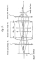
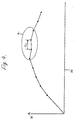
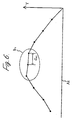
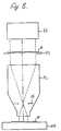
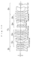
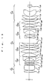
Claims (29)

  1. A projection optical system that projects the image of the first object onto the second object with a fixed reduction ratio comprising, viewed from said first object side, in order of succession, a first group of lenses with positive refractive power, a second group of lenses virtually consists of afocal system, and a third group of lenses with positive refractive power, and
       if the focal length of the entire system is represented by F, a projection magnification of said projection optical system is represented by B, a distance between said first object and said second object is represented by L, and when a ray from the second object side of said projection optical system that is parallel to the optical axis of said projection optical system is incident on said projection optical system, a distance between a point where an extension on the first object side of said ray intercepts the optical axis and said first object plane is represented by e, and a height of said ray on said first object from the optical axis of said projection optical system, when said ray, coming through said projection optical system, reaches said first object is represented by h, then the following conditions should be satisfied. 1.8≦| F /( B · L )| | h / e |≦3/1000
    Figure imgb0148
  2. A projection optical system as claimed in Claim 1, where,
       if the maximum height of said first object from the optical axis of said projection optical system is represented by H, the focal length of the overall system is represented by F, and the projection magnification of said projection optical system is represented by B, then the following condition should be satisfied. | BH / F |≦8/1000
    Figure imgb0149
  3. A projection optical system as claimed in Claim 2, where,
       if the focal length of the entire system is represented by F, and when a ray from the second object side of said projection optical system that is parallel to the optical axis of said projection optical system is incident on said projection optical system, a distance between a point where an extension on the first object side of said ray intercepts the optical axis and said first object plane is represented by e, and a height of said ray on said first object from the optical axis of said projection optical system, when said ray, coming through said projection optical system, reaches said first object is represented by h, and the maximum height of said first object from the optical axis of said projection optical system is represented by H, then the following condition should be satisfied. Fh /( BHe )≦4
    Figure imgb0150
  4. A projection optical system as claimed in Claim 3, where,
       if the focal length of said first group of lenses is represented by f₁, and a focal length of said third group of lenses is represented by f₃, then the following condition should be satisfied. 0.80≦ f 3 / f 1 ≦1.5
    Figure imgb0151
  5. A projection optical system as claimed in Claim 4, where
       if the focal length of said first group of lenses is represented by f₁, and the distance between said first object and said second object is represented by L, then the following condition should be satisfied. 0.05≦ f 1 / L ≦0.3
    Figure imgb0152
  6. A projection optical system as claimed in Claim 5, where,
       if the maximum height of the object from the optical axis of the projection optical system on said first object is by H, and the distance between said first object and said second object is represented by L, then the following condition should be satisfied. 0.03≦ H / L ≦0.2
    Figure imgb0153
  7. A projection optical system as claimed in Claim 6, where,
       said first group of lenses comprises at least 2 or more positive lenses, and
       said second group of lenses comprises at least 4 or more negative lenses, and at least 4 or more positive lenses, and
       and said third group of lenses comprises at least 2 or more positive lenses.
  8. A projection optical system as claimed in Claim 7, where,
       at least one of the groups of lenses of said first, second, and third groups of lenses includes aspherical lenses.
  9. A projection optical system as claimed in Claim 7, where,
       said second group of lenses comprises, viewed from said first object side, in order of succession, at least a first group of sub lenses with negative refractive power, a second group of sub lenses with positive refractive power, and a third group of sub lenses with negative refractive power.
  10. A projection optical system as claimed in Claim 9, where,
       if the focal length of said first group of sub lenses is represented by f₂₁ and the focal length of said second group of lenses is represented by f₂₂, then the following condition should be satisfied. 1.5≦| f 22 / f 21 |≦5
    Figure imgb0154
  11. A projection optical system as claimed in Claim 10, where,
       if the focal length of said third group of lenses is represented by f₂₃, the distance between said first object and said second object is represented by L, then the following condition should be satisfied. 0.02≦| f 23 / L |≦0.10
    Figure imgb0155
  12. A projection optical system as claimed in Claim 11, where,
       if a composite focal length of said first group of lenses, the first group of sub lenses in said second group of lenses, and the second group of sub lenses in said second group of lenses is represented by fa, and the focal length of the third group of sub lenses in the second group of lenses is represented by f₂₃, then the following condition should be satisfied. 4≦| fa / f 23 |
    Figure imgb0156
  13. A projection optical system as claimed in Claim 12, where,
       if the distance between said first object and said second object is represented by L, the focal length of said first group of lenses G1 is represented by f₁, the focal length of said third group of lenses G3 is represented by f₃, and the focal length of the ith group of sub lenses that is ith from the object side in said second group of lenses is represented by f2i, then the following condition should be satisfied. -50≦( L / f 1 )+( L / f 3 )+Σ( L / f 2 i )≦0.5
    Figure imgb0157
  14. A projection optical system as claimed in Claim 13, where,
       said first group of sub lenses comprises at least 2 or more negative lenses, and
       said second group of sub lenses comprises at least 4 or more positive lenses, and
       said third group of sub lenses comprises at least 2 or more negative lenses.
  15. A projection optical system as claimed in Claim 14, where,
       said second group of sub lenses comprises 2 biconcave lenses.
  16. A projection optical system as claimed in Claim 15, where,
       if an angle of incidence of a paraxial marginal ray as the paraxial marginal ray from an axial object point on said first object enters in said first group of lenses is represented by u₁, an angle of incidence of the paraxial marginal ray as the paraxial marginal ray from the axial object point on said first object enters in said second group of lenses is represented by u₂, an angle of emergence of the paraxial marginal ray as the paraxial marginal ray from the axial object point on said first object emerges from said second group of lenses is represented by u₂', the angle of emergence of the paraxial marginal ray as the paraxial marginal ray from the axial object point on said first object emerges from said third group of lenses is represented by u₃', then the following conditions should be satisfied. | u 2 / u 1 |≦0.5 | u 2 '/ u 3 '|≦0.5
    Figure imgb0158
  17. A projection optical system as claimed in Claim 16, where,
       if the focal length of said first group of lenses is represented by f₁, the focal length of said second group of lenses is represented by f₂, and the focal length of the third group of lenses is represented by f₃, then the following conditions should be satisfied. | f 2 |/ f 1 >1 | f 2 |/ f 3 >1
    Figure imgb0159
  18. A projection optical system as claimed in Claim 3, where,
       said first group of lenses comprises at least 2 or more positive lenses, and
       said third group of lenses comprises at least 2 or more positive lenses, and
       said second group of lenses comprises, viewed from said first object side, in order of succession, the first group of lenses with negative refractive power, the second group of sub lenses with positive refractive power, and the third group of lenses with negative refractive power, and
       said first group of sub lenses comprises at least 2 or more negative lenses, and
       said second group of sub lenses comprises at least 4 or more positive lenses, and
       said third group of sub lenses comprises at least 2 or more negative lenses.
  19. A projection optical system as claimed in Claim 3, where,
       said second group of lenses comprises, viewed from said first object side, in order of succession, the first group of sub lenses with negative refractive power, the second group of sub lenses with positive refractive power, the third group of sub lenses with negative refractive power, and the fourth group of sub lenses with positive refractive power.
  20. A projection optical system as claimed in Claim 19, where,
       said first group of lenses comprises at least 2 or more positive lenses, and
       said third group of lenses comprises at least 2 or more positive lenses, and
       said first group of sub lenses comprises at least 2 or more negative lenses, and
       said second group of sub lenses comprises at least 4 or more positive lenses, and
       said third group of sub lenses comprises at least 2 or more negative lenses, and
       said fourth group of sub lenses comprises at least 2 or more positive lenses.
  21. A projection aligner comprising
       an illumination means that illuminates the first object on which a fixed pattern is formed,
       the projection optical system which projects said image of the first object onto the second object,
       the first holding means that holds said first object,
       the second holding means that holds said second object, and
       said projection optical system comprising, viewed from said first object side, in order of succession, the first group of lenses with positive refractive power, the second group of lenses virtually consists of afocal system, and the third group of lenses with positive refractive power, and
       if the focal length of the overall system is represented by F, the projection magnification of said projection optical system is represented by B, the distance between said first object and said second object is represented by L, and when a ray from the second object side of said projection optical system that is parallel to the optical axis of said projection optical system is incident on said projection optical system, a distance between a point where an extension on the first object side of said ray intercepts the optical axis and said first object plane is represented by e, and a height of said ray on said first object from the optical axis of said projection optical system, when said ray, coming through said projection optical system, reaches said first object is represented by h, then the following conditions should be satisfied. 1.8≦| F /( B · L )| | h / e |≦3/1000
    Figure imgb0160
  22. A projection aligner as claimed in Claim 21, where,
       said first group of lenses comprises at least 2 or more positive lenses, and
       said third group of lenses comprises at least 2 or more positive lenses, and
       said second group of lenses comprises, viewed from said first object side, in order of succession, the first group of lenses with negative refractive power, the second group of sub lenses with positive refractive power, and the third group of lenses with negative refractive power, and
       said first group of sub lenses comprises at least 2 or more negative lenses, and
       said second group of sub lenses comprises at least 4 or more positive lenses, and
       said third group of sub lenses comprises at least 2 or more negative lenses.
  23. A projection aligner as claimed in Claim 21, where,
       said second group of lenses comprises, viewed from said first object side, in order of succession, the first group of sub lenses with negative refractive power, the second group of sub lenses with positive refractive power, the third group of sub lenses with negative refractive power, and the fourth group of sub lenses with positive refractive power.
  24. A projection aligner as claimed in Claim 23, where,
       said first group of lenses comprises at least 2 or more positive lenses, and
       said third group of lenses comprises at least 2 or more positive lenses, and
       said first group of sub lenses comprises at least 2 or more negative lenses, and
       said second group of sub lenses comprises at least 4 or more positive lenses, and
       said third group of sub lenses comprises at least 2 or more negative lenses, and
       said fourth group of sub lenses comprises at least 2 or more positive lenses.
  25. A projection aligner as claimed in Claim 21, where,
       if the maximum height of said first object from the optical axis of said projection optical system is represented by H, the focal length of the entire system is represented by F, and the projection magnification of said projection optical system is represented by B, then the following condition should be satisfied. | BH / F |≦8/1000
    Figure imgb0161
  26. A projection aligner as claimed in Claim 21, where,
       if the focal length of the entire system is represented by F, and when a ray from the second object side of said projection optical system that is parallel to the optical axis of said projection optical system is incident on said projection optical system, a distance between a point where an extension on the first object side of said ray intercepts the optical axis and said first object plane is represented by e, and a height of said ray on said first object from the optical axis of said projection optical system, when said ray, coming through said projection optical system, reaches said first object is represented by h, and the maxim height of said first object from the optical axis of said projection optical system is represented by H, then the following condition should be satisfied. | Fh /( BHe )|≦4
    Figure imgb0162
  27. A projection aligner as claimed in Claim 21, where,
       if the focal length of said first group of lenses is represented by f₁, and the focal length of said third group of lenses is represented by f₃, then the following condition should be satisfied. 0.80≦ f 3 / f 1 ≦1.5
    Figure imgb0163
  28. A projection aligner as claimed in Claim 21, where,
       if the focal length of said first group of lenses is represented by f₁, and the distance between said first object and said second object is represented by L, then the following condition should be satisfied. 0.05≦ f 1/ L ≦0.3
    Figure imgb0164
  29. A projection optical system as claimed in Claim 21, where,
       if the maximum height of the object from the optical axis of the projection optical system on said first object is represented by H, and the distance between said first object and said second object is represented by L, then the following condition should be satisfied. 0.03≦ H / L ≦0.2
    Figure imgb0165
EP95117090A 1994-11-10 1995-10-30 Projection optical system and projection exposure apparatus Withdrawn EP0712019A3 (en)

Priority Applications (1)

Application Number Priority Date Filing Date Title
EP20000127533 EP1091230A3 (en) 1994-11-10 1995-10-30 Projection optical system that projects an image of a pattern formed on a reticle onto a substrate

Applications Claiming Priority (2)

Application Number Priority Date Filing Date Title
US33764794A 1994-11-10 1994-11-10
US337647 1999-06-22

Related Child Applications (1)

Application Number Title Priority Date Filing Date
EP20000127533 Division EP1091230A3 (en) 1994-11-10 1995-10-30 Projection optical system that projects an image of a pattern formed on a reticle onto a substrate

Publications (2)

Publication Number Publication Date
EP0712019A2 true EP0712019A2 (en) 1996-05-15
EP0712019A3 EP0712019A3 (en) 1997-10-08

Family

ID=23321415

Family Applications (2)

Application Number Title Priority Date Filing Date
EP95117090A Withdrawn EP0712019A3 (en) 1994-11-10 1995-10-30 Projection optical system and projection exposure apparatus
EP20000127533 Withdrawn EP1091230A3 (en) 1994-11-10 1995-10-30 Projection optical system that projects an image of a pattern formed on a reticle onto a substrate

Family Applications After (1)

Application Number Title Priority Date Filing Date
EP20000127533 Withdrawn EP1091230A3 (en) 1994-11-10 1995-10-30 Projection optical system that projects an image of a pattern formed on a reticle onto a substrate

Country Status (5)

Country Link
US (2) US5805344A (en)
EP (2) EP0712019A3 (en)
JP (1) JPH08179204A (en)
KR (1) KR100387003B1 (en)
DE (1) DE1091230T1 (en)

Cited By (17)

* Cited by examiner, † Cited by third party
Publication number Priority date Publication date Assignee Title
EP0721150A3 (en) * 1995-01-06 1997-04-09 Nippon Kogaku Kk Projection optical system and exposure apparatus using the same
EP0803755A2 (en) 1996-04-25 1997-10-29 Nikon Corporation Projection optical system and exposure apparatus with the same
US5808814A (en) * 1996-07-18 1998-09-15 Nikon Corporation Short wavelength projection optical system
EP0869382A2 (en) * 1997-04-03 1998-10-07 Nikon Corporation Projection optical system
US5930049A (en) * 1996-10-01 1999-07-27 Nikon Corporation Projection optical system and method of using such system for manufacturing devices
US6008884A (en) * 1997-04-25 1999-12-28 Nikon Corporation Projection lens system and apparatus
US6259508B1 (en) 1998-01-22 2001-07-10 Nikon Corporation Projection optical system and exposure apparatus and method
US6333781B1 (en) 1997-07-24 2001-12-25 Nikon Corporation Projection optical system and exposure apparatus and method
US6349005B1 (en) 1998-11-30 2002-02-19 Carl-Zeiss-Stiftung Microlithographic reduction objective, projection exposure equipment and process
USRE38403E1 (en) 1994-11-10 2004-01-27 Nikon Corporation Projection optical system and projection exposure apparatus
USRE38421E1 (en) 1994-04-28 2004-02-10 Nikon Corporation Exposure apparatus having catadioptric projection optical system
USRE38438E1 (en) 1994-08-23 2004-02-24 Nikon Corporation Catadioptric reduction projection optical system and exposure apparatus having the same
US6700645B1 (en) 1998-01-22 2004-03-02 Nikon Corporation Projection optical system and exposure apparatus and method
US6954316B2 (en) 2000-12-22 2005-10-11 Carl Zeiss Smt Projection objective
USRE39296E1 (en) 1993-03-12 2006-09-19 Nikon Corporation Catadioptric projection systems
US9726979B2 (en) 2004-05-17 2017-08-08 Carl Zeiss Smt Gmbh Catadioptric projection objective with intermediate images
US9772478B2 (en) 2004-01-14 2017-09-26 Carl Zeiss Smt Gmbh Catadioptric projection objective with parallel, offset optical axes

Families Citing this family (23)

* Cited by examiner, † Cited by third party
Publication number Priority date Publication date Assignee Title
USRE38465E1 (en) 1994-12-14 2004-03-16 Nikon Corporation Exposure apparatus
JP3500745B2 (en) * 1994-12-14 2004-02-23 株式会社ニコン Projection optical system, projection exposure apparatus, and projection exposure method
DE19548805A1 (en) * 1995-12-27 1997-07-03 Zeiss Carl Fa REMA lens for microlithography projection exposure systems
JPH09325275A (en) * 1996-06-04 1997-12-16 Canon Inc Illuminator and projection exposure device using the same
JPH1048517A (en) * 1996-08-07 1998-02-20 Nikon Corp Projection optical system
US5990926A (en) * 1997-07-16 1999-11-23 Nikon Corporation Projection lens systems for excimer laser exposure lithography
JPH1195095A (en) 1997-09-22 1999-04-09 Nikon Corp Projection optical system
DE19942281A1 (en) * 1999-05-14 2000-11-16 Zeiss Carl Fa Projection lens has system filter screen, constrictions and bulges, negative lens, and positive lenses
DE19855157A1 (en) * 1998-11-30 2000-05-31 Zeiss Carl Fa Projection lens
JP2002531878A (en) * 1998-11-30 2002-09-24 カール−ツアイス−スチフツング Large numerical aperture projection lens with minimum aperture aberration
JP3359302B2 (en) 1999-06-14 2002-12-24 キヤノン株式会社 Projection exposure equipment
US6867922B1 (en) 1999-06-14 2005-03-15 Canon Kabushiki Kaisha Projection optical system and projection exposure apparatus using the same
JP2000356741A (en) 1999-06-14 2000-12-26 Canon Inc Projection optical system
US7203007B2 (en) * 2000-05-04 2007-04-10 Carl Zeiss Smt Ag Projection exposure machine comprising a projection lens
JP3308972B1 (en) * 2001-01-16 2002-07-29 有限会社セルフセキュリティ Medication confirmation support device
JP2002244034A (en) 2001-02-21 2002-08-28 Nikon Corp Projection optical system and exposure device provided with it
JP2002323652A (en) 2001-02-23 2002-11-08 Nikon Corp Projection optical system, projection exposure apparatus provided with the same, and projection exposure method
JP4292497B2 (en) * 2002-04-17 2009-07-08 株式会社ニコン Projection optical system, exposure apparatus, and exposure method
US8208198B2 (en) 2004-01-14 2012-06-26 Carl Zeiss Smt Gmbh Catadioptric projection objective
JP2007114750A (en) * 2005-09-09 2007-05-10 Asml Netherlands Bv Projection system design method, lithography apparatus, and device manufacturing method
US10976535B2 (en) 2016-03-30 2021-04-13 Optical Wavefront Laboratories Multiple camera microscope imaging with patterned illumination
US11561462B2 (en) * 2020-08-21 2023-01-24 Union Optech Co., Ltd. Optical system and projection device
CN113093480B (en) * 2021-04-15 2024-02-13 之江实验室 Parallel exposure inhibition super diffraction limit laser direct writing objective lens

Citations (3)

* Cited by examiner, † Cited by third party
Publication number Priority date Publication date Assignee Title
JPS63118115A (en) 1986-11-06 1988-05-23 Sigma:Kk Projection lens
JPH04157412A (en) 1990-10-22 1992-05-29 Olympus Optical Co Ltd Projector lens system
JPH05173065A (en) 1991-10-24 1993-07-13 Olympus Optical Co Ltd Reduction projection lens

Family Cites Families (76)

* Cited by examiner, † Cited by third party
Publication number Priority date Publication date Assignee Title
US3504961A (en) 1968-04-01 1970-04-07 Perkin Elmer Corp Modified double gauss objective
US3685884A (en) * 1971-01-29 1972-08-22 Olympus Optical Co 1 x objective for projection printing
US3897138A (en) 1971-11-24 1975-07-29 Canon Kk Projection lens for mask pattern printing
US3737215A (en) 1972-04-06 1973-06-05 Eastman Kodak Co Six element unit magnification lens
JPS5336326B2 (en) 1972-12-26 1978-10-02
JPS5416410B2 (en) 1974-03-07 1979-06-22
JPS5820402B2 (en) 1975-10-14 1983-04-22 オリンパス光学工業株式会社 All-purpose lens
JPS581763B2 (en) 1978-06-19 1983-01-12 旭光学工業株式会社 1-magnification copying lens with diffraction-limited resolution
JPS56165111A (en) * 1980-05-26 1981-12-18 Nippon Kogaku Kk <Nikon> Telecentric illuminating system
JPS584112A (en) 1981-06-30 1983-01-11 Olympus Optical Co Ltd Standard lens with wide picture angle
JPS5878115A (en) * 1981-11-04 1983-05-11 Nippon Kogaku Kk <Nikon> Auxiliary condenser lens for telecentric illumination
JPS58147708A (en) 1982-02-26 1983-09-02 Nippon Kogaku Kk <Nikon> Optical device for illumination
JPS58150924A (en) * 1982-03-04 1983-09-07 Nippon Kogaku Kk <Nikon> Optical system maintaining double conjugation
US4666273A (en) 1983-10-05 1987-05-19 Nippon Kogaku K. K. Automatic magnification correcting system in a projection optical apparatus
US4812028A (en) 1984-07-23 1989-03-14 Nikon Corporation Reflection type reduction projection optical system
US4701035A (en) 1984-08-14 1987-10-20 Canon Kabushiki Kaisha Reflection optical system
US4779966A (en) 1984-12-21 1988-10-25 The Perkin-Elmer Corporation Single mirror projection optical system
JPS61156737A (en) 1984-12-27 1986-07-16 Canon Inc Catadioptric system
US4757354A (en) * 1986-05-02 1988-07-12 Matsushita Electrical Industrial Co., Ltd. Projection optical system
JPS62266513A (en) 1986-05-14 1987-11-19 Canon Inc Projecting exposure optical system
EP0266203B1 (en) * 1986-10-30 1994-07-06 Canon Kabushiki Kaisha An illumination device
US4772107A (en) 1986-11-05 1988-09-20 The Perkin-Elmer Corporation Wide angle lens with improved flat field characteristics
US4770477A (en) 1986-12-04 1988-09-13 The Perkin-Elmer Corporation Lens usable in the ultraviolet
US4747678A (en) 1986-12-17 1988-05-31 The Perkin-Elmer Corporation Optical relay system with magnification
JPH0786647B2 (en) * 1986-12-24 1995-09-20 株式会社ニコン Lighting equipment
JPS63316817A (en) 1987-06-19 1988-12-26 Dainippon Screen Mfg Co Ltd Telecentric image forming optical system capable of power variation
JPS6419317A (en) 1987-07-14 1989-01-23 Dainippon Screen Mfg Telecentric image formation optical system with large picture plane size
DE68916451T2 (en) 1988-03-11 1994-11-17 Matsushita Electric Ind Co Ltd Optical projection system.
US4953960A (en) 1988-07-15 1990-09-04 Williamson David M Optical reduction system
US5253110A (en) 1988-12-22 1993-10-12 Nikon Corporation Illumination optical arrangement
JP2847883B2 (en) 1990-03-30 1999-01-20 株式会社ニコン Catadioptric reduction projection optical system
US5220454A (en) 1990-03-30 1993-06-15 Nikon Corporation Cata-dioptric reduction projection optical system
JPH0442208A (en) 1990-06-08 1992-02-12 Dainippon Screen Mfg Co Ltd Telecentric projection lens
US5089913A (en) 1990-07-11 1992-02-18 International Business Machines Corporation High resolution reduction catadioptric relay lens
US5241423A (en) 1990-07-11 1993-08-31 International Business Machines Corporation High resolution reduction catadioptric relay lens
US5052763A (en) 1990-08-28 1991-10-01 International Business Machines Corporation Optical system with two subsystems separately correcting odd aberrations and together correcting even aberrations
JP3353902B2 (en) * 1990-12-12 2002-12-09 オリンパス光学工業株式会社 Projection lens system
US5402267A (en) 1991-02-08 1995-03-28 Carl-Zeiss-Stiftung Catadioptric reduction objective
NL194844C (en) 1991-02-08 2003-04-03 Zeiss Carl Fa Catadioptric reduction objective.
JP2830492B2 (en) 1991-03-06 1998-12-02 株式会社ニコン Projection exposure apparatus and projection exposure method
US5506684A (en) 1991-04-04 1996-04-09 Nikon Corporation Projection scanning exposure apparatus with synchronous mask/wafer alignment system
JPH0534593A (en) 1991-05-22 1993-02-12 Olympus Optical Co Ltd Contraction projection lens
US5668673A (en) 1991-08-05 1997-09-16 Nikon Corporation Catadioptric reduction projection optical system
US5274503A (en) 1991-08-23 1993-12-28 Eastman Kodak Company High aperture finite conjugate lens system suitable for use as a micro relay lens
US5272568A (en) 1991-12-11 1993-12-21 Eastman Kodak Company High aperture finite conjugate lens system
US5258777A (en) 1991-08-23 1993-11-02 Eastman Kodak Company Thermal printer system with a high aperture micro relay lens system
JPH06501792A (en) 1991-08-23 1994-02-24 イーストマン・コダック・カンパニー Finite conjugate lens system with high numerical aperture suitable for use as a micro relay lens and printer using the lens system
JP2731481B2 (en) 1992-01-23 1998-03-25 大日本スクリーン製造株式会社 Telecentric imaging optics
US5212593A (en) 1992-02-06 1993-05-18 Svg Lithography Systems, Inc. Broad band optical reduction system using matched multiple refractive element materials
US5333035A (en) 1992-05-15 1994-07-26 Nikon Corporation Exposing method
US5383052A (en) * 1992-05-27 1995-01-17 Dainippon Screen Mfg. Co., Ltd. Afocal optical system and multibeam recording apparatus comprising the same
JP3374413B2 (en) 1992-07-20 2003-02-04 株式会社ニコン Projection exposure apparatus, projection exposure method, and integrated circuit manufacturing method
US5406415A (en) 1992-09-22 1995-04-11 Kelly; Shawn L. Imaging system for a head-mounted display
JP2750062B2 (en) 1992-12-14 1998-05-13 キヤノン株式会社 Catadioptric optical system and projection exposure apparatus having the optical system
US5537260A (en) 1993-01-26 1996-07-16 Svg Lithography Systems, Inc. Catadioptric optical reduction system with high numerical aperture
US5323263A (en) 1993-02-01 1994-06-21 Nikon Precision Inc. Off-axis catadioptric projection system
US5591958A (en) 1993-06-14 1997-01-07 Nikon Corporation Scanning exposure method and apparatus
US5592329A (en) 1993-02-03 1997-01-07 Nikon Corporation Catadioptric optical system
JP3747951B2 (en) 1994-11-07 2006-02-22 株式会社ニコン Catadioptric optics
US5636066A (en) 1993-03-12 1997-06-03 Nikon Corporation Optical apparatus
JP3747958B2 (en) 1995-04-07 2006-02-22 株式会社ニコン Catadioptric optics
JPH06313845A (en) 1993-04-28 1994-11-08 Olympus Optical Co Ltd Projection lens system
JPH06331941A (en) 1993-05-19 1994-12-02 Olympus Optical Co Ltd Projection lens system
US5534970A (en) 1993-06-11 1996-07-09 Nikon Corporation Scanning exposure apparatus
US5515207A (en) 1993-11-03 1996-05-07 Nikon Precision Inc. Multiple mirror catadioptric optical system
JP3360387B2 (en) * 1993-11-15 2002-12-24 株式会社ニコン Projection optical system and projection exposure apparatus
JP3396935B2 (en) * 1993-11-15 2003-04-14 株式会社ニコン Projection optical system and projection exposure apparatus
JP3395801B2 (en) 1994-04-28 2003-04-14 株式会社ニコン Catadioptric projection optical system, scanning projection exposure apparatus, and scanning projection exposure method
DE4417489A1 (en) 1994-05-19 1995-11-23 Zeiss Carl Fa High-aperture catadioptric reduction lens for microlithography
JPH0817719A (en) 1994-06-30 1996-01-19 Nikon Corp Projection aligner
JPH08179204A (en) 1994-11-10 1996-07-12 Nikon Corp Projection optical system and projection aligner
JP3500745B2 (en) 1994-12-14 2004-02-23 株式会社ニコン Projection optical system, projection exposure apparatus, and projection exposure method
JPH08203812A (en) 1995-01-30 1996-08-09 Nikon Corp Reflection-refraction reduction projection optical system and aligner
JP3624973B2 (en) 1995-10-12 2005-03-02 株式会社ニコン Projection optical system
JPH1010431A (en) 1996-06-20 1998-01-16 Nikon Corp Catadioptric system
JP3282527B2 (en) 1996-12-27 2002-05-13 富士ゼロックス株式会社 Image coding device

Patent Citations (3)

* Cited by examiner, † Cited by third party
Publication number Priority date Publication date Assignee Title
JPS63118115A (en) 1986-11-06 1988-05-23 Sigma:Kk Projection lens
JPH04157412A (en) 1990-10-22 1992-05-29 Olympus Optical Co Ltd Projector lens system
JPH05173065A (en) 1991-10-24 1993-07-13 Olympus Optical Co Ltd Reduction projection lens

Cited By (23)

* Cited by examiner, † Cited by third party
Publication number Priority date Publication date Assignee Title
USRE39296E1 (en) 1993-03-12 2006-09-19 Nikon Corporation Catadioptric projection systems
USRE39024E1 (en) 1994-04-28 2006-03-21 Nikon Corporation Exposure apparatus having catadioptric projection optical system
USRE38421E1 (en) 1994-04-28 2004-02-10 Nikon Corporation Exposure apparatus having catadioptric projection optical system
USRE38438E1 (en) 1994-08-23 2004-02-24 Nikon Corporation Catadioptric reduction projection optical system and exposure apparatus having the same
USRE38403E1 (en) 1994-11-10 2004-01-27 Nikon Corporation Projection optical system and projection exposure apparatus
USRE37846E1 (en) 1995-01-06 2002-09-17 Nikon Corporation Projection optical system and exposure apparatus using the same
US5835285A (en) * 1995-01-06 1998-11-10 Nikon Corporation Projection optical system and exposure apparatus using the same
EP0721150A3 (en) * 1995-01-06 1997-04-09 Nippon Kogaku Kk Projection optical system and exposure apparatus using the same
EP0803755A2 (en) 1996-04-25 1997-10-29 Nikon Corporation Projection optical system and exposure apparatus with the same
US5808814A (en) * 1996-07-18 1998-09-15 Nikon Corporation Short wavelength projection optical system
US5930049A (en) * 1996-10-01 1999-07-27 Nikon Corporation Projection optical system and method of using such system for manufacturing devices
EP0869382A3 (en) * 1997-04-03 1999-05-06 Nikon Corporation Projection optical system
US6088171A (en) * 1997-04-03 2000-07-11 Nikon Corporation Projection optical system
EP0869382A2 (en) * 1997-04-03 1998-10-07 Nikon Corporation Projection optical system
US6008884A (en) * 1997-04-25 1999-12-28 Nikon Corporation Projection lens system and apparatus
US6333781B1 (en) 1997-07-24 2001-12-25 Nikon Corporation Projection optical system and exposure apparatus and method
US6259508B1 (en) 1998-01-22 2001-07-10 Nikon Corporation Projection optical system and exposure apparatus and method
US6700645B1 (en) 1998-01-22 2004-03-02 Nikon Corporation Projection optical system and exposure apparatus and method
US6349005B1 (en) 1998-11-30 2002-02-19 Carl-Zeiss-Stiftung Microlithographic reduction objective, projection exposure equipment and process
EP1686405A1 (en) 1998-11-30 2006-08-02 Carl Zeiss SMT AG Microlithographic reduction lens with five lens groups
US6954316B2 (en) 2000-12-22 2005-10-11 Carl Zeiss Smt Projection objective
US9772478B2 (en) 2004-01-14 2017-09-26 Carl Zeiss Smt Gmbh Catadioptric projection objective with parallel, offset optical axes
US9726979B2 (en) 2004-05-17 2017-08-08 Carl Zeiss Smt Gmbh Catadioptric projection objective with intermediate images

Also Published As

Publication number Publication date
JPH08179204A (en) 1996-07-12
US5805344A (en) 1998-09-08
EP1091230A9 (en) 2001-07-11
DE1091230T1 (en) 2001-09-20
KR960018769A (en) 1996-06-17
KR100387003B1 (en) 2003-08-21
EP1091230A2 (en) 2001-04-11
EP0712019A3 (en) 1997-10-08
EP1091230A3 (en) 2004-02-11
USRE38403E1 (en) 2004-01-27

Similar Documents

Publication Publication Date Title
EP0712019A2 (en) Projection optical system and projection exposure apparatus
US6157498A (en) Dual-imaging optical system
US5515207A (en) Multiple mirror catadioptric optical system
JP3500745B2 (en) Projection optical system, projection exposure apparatus, and projection exposure method
US5831776A (en) Projection optical system and projection exposure apparatus
JP3396935B2 (en) Projection optical system and projection exposure apparatus
EP0869383B1 (en) Catadioptric optical system
US6631036B2 (en) Catadioptric objective
US5555479A (en) Reduction projection lens system including refractive and diffractive optical elements
US7301707B2 (en) Projection optical system and method
US6084723A (en) Exposure apparatus
KR100573913B1 (en) Iprojection optical system and exposure apparatus having the same
EP0332201A2 (en) Optical projection system
JPH09105861A (en) Projection optical system
JPH08334695A (en) Catadioptric system
US6088171A (en) Projection optical system
KR20100052515A (en) Chromatically corrected catadioptric objective and projection exposure apparatus including the same
EP0813085A2 (en) Catadioptric system for photolithography
JPH10115779A (en) Projection optical system
US6538821B2 (en) Projection optical system
EP0604093B1 (en) Catadioptric reduction projection optical system
US5771125A (en) Catadioptric system for photolithography
US7046459B1 (en) Catadioptric reductions lens
JPH1010429A (en) Double image-formation optical system
USRE42570E1 (en) Catadioptric objective

Legal Events

Date Code Title Description
PUAI Public reference made under article 153(3) epc to a published international application that has entered the european phase

Free format text: ORIGINAL CODE: 0009012

AK Designated contracting states

Kind code of ref document: A2

Designated state(s): DE FR GB IT NL

PUAL Search report despatched

Free format text: ORIGINAL CODE: 0009013

AK Designated contracting states

Kind code of ref document: A3

Designated state(s): DE FR GB IT NL

17P Request for examination filed

Effective date: 19971118

17Q First examination report despatched

Effective date: 19991013

18W Application withdrawn

Effective date: 20041222

STAA Information on the status of an ep patent application or granted ep patent

Free format text: STATUS: THE APPLICATION HAS BEEN WITHDRAWN

R18W Application withdrawn (corrected)

Effective date: 20041222