EP0712224A2 - Dealing board - Google Patents
Dealing board Download PDFInfo
- Publication number
- EP0712224A2 EP0712224A2 EP96100176A EP96100176A EP0712224A2 EP 0712224 A2 EP0712224 A2 EP 0712224A2 EP 96100176 A EP96100176 A EP 96100176A EP 96100176 A EP96100176 A EP 96100176A EP 0712224 A2 EP0712224 A2 EP 0712224A2
- Authority
- EP
- European Patent Office
- Prior art keywords
- dealing board
- main body
- panel
- cover
- led
- Prior art date
- Legal status (The legal status is an assumption and is not a legal conclusion. Google has not performed a legal analysis and makes no representation as to the accuracy of the status listed.)
- Granted
Links
Images


Classifications
-
- H—ELECTRICITY
- H04—ELECTRIC COMMUNICATION TECHNIQUE
- H04M—TELEPHONIC COMMUNICATION
- H04M1/00—Substation equipment, e.g. for use by subscribers
- H04M1/02—Constructional features of telephone sets
- H04M1/23—Construction or mounting of dials or of equivalent devices; Means for facilitating the use thereof
-
- A—HUMAN NECESSITIES
- A47—FURNITURE; DOMESTIC ARTICLES OR APPLIANCES; COFFEE MILLS; SPICE MILLS; SUCTION CLEANERS IN GENERAL
- A47B—TABLES; DESKS; OFFICE FURNITURE; CABINETS; DRAWERS; GENERAL DETAILS OF FURNITURE
- A47B21/00—Tables or desks for office equipment, e.g. typewriters, keyboards
-
- H—ELECTRICITY
- H04—ELECTRIC COMMUNICATION TECHNIQUE
- H04M—TELEPHONIC COMMUNICATION
- H04M1/00—Substation equipment, e.g. for use by subscribers
- H04M1/02—Constructional features of telephone sets
- H04M1/0289—Telephone sets for operators
-
- A—HUMAN NECESSITIES
- A47—FURNITURE; DOMESTIC ARTICLES OR APPLIANCES; COFFEE MILLS; SPICE MILLS; SUCTION CLEANERS IN GENERAL
- A47B—TABLES; DESKS; OFFICE FURNITURE; CABINETS; DRAWERS; GENERAL DETAILS OF FURNITURE
- A47B2200/00—General construction of tables or desks
- A47B2200/0066—Workstations
- A47B2200/0078—Control consoles or desks
Definitions
- the present invention relates to a dealing board provided with various telephoning functions and adapted to be used as a terminal of a financial institution, such as banks and securities corporations.
- the dealing board used as a financial terminal has a telephone function, however with it has become of a wide variety recently, several functions of the terminal are grouped and panellarized in units. Customers can select their necessary units other than basic units and combine these selected units in order to construct the particular and custom-built dealing board.
- the dealing board has telephone functions, it is constructed by a hand-set, a set of dialing buttons, function buttons, a display, a microphone, a speaker, and a set of switches operating and controlling these instruments above.
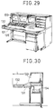
- Figs 29 and 30 respectively show perspective views of the conventional dealing board of the kind above.
- a main body 131 of the dealing board is installed on a desk 132.
- a display system 133 displaying information on economy is installed on the front portion of the desk 132 and a control box 134 is placed under the desk.
- a control panel 139a of the main body 131 of the dealing board is apt to be declined by an angle of range of 10° - 30° in order to make the operability of the dealing board good.
- the main body 131 of the dealing board consists of the control panel 139a, the function buttons 135, a pair of print substrates 137 and 138 on which function circuits are mounted, and a case 139 containing these parts above.
- These print substrates 137 and 138 are assembled in parallel with each other through a pair of bushings 140 and the assembled is installed on the inner face of the front-declined control panel 139a by screws 141.
- control panel 139a is installed on the upper face of the box-like case 139 so as to be inclined down toward the front, the bottom face 139d of the case 139 is placed horizontally, and the front and the rear faces 139b and 139c of the case 139 are situated at a right angle relative to the bottom face 139d.
- the case 139 of the dealing board main body 131 is inserted downward through an opening portion 132a of the desk 132 and the case 139 is fixed in place by a set of fixtures 145.
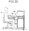
- a pair of vertical walls of the case 139 is placed at a right angle to the top plate of the desk 132, so when a user A sits on a chair in back of the dealing board, his knee B touches the front face 139b or a corner of the case as shwon in Fig 33 blocking up free movement of the knee B of the user, as well the person cannot sit on the chair comfortably creating early fatigure of the user disadvantageously.
- the main body 131 of the conventional dealing board has slanted print substrates 137 and 138 on which function buttons 135 are mounted and other print substrates 142, 143, and 144 fixed to the bottom of the case 139 are placed in horizontal posture, whereby useless space H is created between the set of print substrates 137 and 138, another set of print substrates 142, 143, and 144.
- the whole size of the case 139 becomes large, and heat generated from electronic parts mounted on the horizontal print substrates 143 and 142 is apt to be blocked by the top and the lower print substrates 143 and 144 and escapes through thermal stream 146, resulting in a bad heat radiation of the main body 131 of the dealing board.
- the appropriate declining angle ⁇ of the dealing board varies according to the particular customer of the borad, so that it has been necessary to manufacture the main body 131 of the dealing board having various declining angle ⁇ according to the particular desire of the user. That is, it is difficult to standarize the angle and a number of kinds of the main body or the dealing board must be produced, resulting in a difficulty of management for the productions of the board.
- the conventional dealing board has as shown in Figs 34 - 37 a panel unit 154 adapted to be used by the user as communication means, which unit includes a dial operation part 155, a display portion 157 of such as liquid crystal, a number of key units 156 having automatic dialing functions, a volume 158 for controlling the volume or darkness or brightness of the microphone and other key units and the display 157, and other control panels for various switches.
- a dial operation part 155 a display portion 157 of such as liquid crystal
- a number of key units 156 having automatic dialing functions a volume 158 for controlling the volume or darkness or brightness of the microphone and other key units and the display 157
- other control panels for various switches.
- These various parts contained in the panel unit 154 are arranged on a panel 159 and connected and secured to print substrates 160-1 and 160-2.
- the control panel of the dealing board is constructed by the parts of the panel unit 154 including a hand-set.
- the dealing board deals with in function a number of clients or business connections and the particular client can be called out with a single touch operation of buttons through the automatic dialing function.
- the automatic dialing function includes a display function depicting the name or symbol of the customer through a set of light emitting diodes in order to indicate the customer called out, which display function being placed near the key unit 156 of the automatic dial, and other function indicating an arrival of a telephone call or an existence of a caller.
- the names of customers can be memorized in the dealing board by the dialing function, but it is necessary to install on the board of the panel unit 154 consisting of a number of key switches. It is preferable to construct the control panel of the dealing board by the panel unit 154 unitizing or grouping various functions in their kinds, because the dealing board has a number of functions. Consequently, the dealing board is constructed by selecting and combining function units, such as a display 113 and the like shown in Fig 23, necessary to the customer except the basic function unit.
- the conventional dealing board is mounted on the desk and a number of desks having the dealing boards mounted thereon are placed in an office room.
- the desk with the dealing board has a display apparatus for selecting and displaying various economy information, book shelves and drawers. It is apparent that consequently a predetermined space of the desk top board is necessary to make operation of the dealing board easy and convenient. However, it is need to restrict the size of the desk in order to make many desks accommodated in the dealing room. When the size of the desk is limitted, it is necessary to shorten the depth of the desk obtaining small desks.
- the dealing board is constructed by a panel unit 154 as described above having multi-function.
- the key switch 165 shown in Fig 38 of the key unit 156 with automatic dialing function has an electric conductive contact rubber 165-2 used as a movable contact and a stable contact 165-3, which contact rubber being covered by a case 165-1 and stable contact being fixed on the top face of the case 165-1.
- a terminal 165-4 connected to the stable contact 165-3 is soldered to be fixed to the print substrate 160-1.
- a protective resistor 162-1 must be arranged on the outside of the key switch 165 causing hindrance to a miniaturization of the panel unit 154.
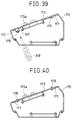
- the panel unit 154 has been fixed to an opening portion of the main body of the dealing board by the method shown in Fig 39.
- the panel 173 is fixed to the opening portion of the case 170 by securing the fixing piece 171 to the opening portion and driving the screw 179 to fasten the panel 173 fitted in the opening portion from the top to the fixing piece 171.
- the reference numeral 173a shown indicates function buttons placed in the panel 173.
- the case 170 has a plurality of panels 173 neatly arranged and secured thereto and the gap between panels 173 is adjusted neatly to the fixed distance obtaining a good appearance. Consequently, when the case 170 must turn over as mentioned above and the panels 173 are secured thereto, it is necessary to turn over the case 170 and exchange several panels 173 every time it is intended to change the combination of the panels 173. When it is found that the gaps between the panels are not equal after the exchange, the case 170 must be again turned over and repeats the same work. It is explicitly troublesome and time-consuming.
- control panel of the dealing board main board is declined downwardly in order to develop an operability of the control panel and there is no space, pencils or other writing instruments and the like are held thereon, on the panel 173, so that when a pencil of writing instrument carelessly is putted on the slanted panel 173, the instrument will roll down from the panel and be missed hindering a smooth working.
- the conventional dealing board generally used as a financial terminal deals with transactions of bonds, foreign exchanges, and stocks through telephone lines, so some telephoning functions are installed on the board.
- the telephoning function has an one-touch or one-switching function for calling a customer instantly or by one-pushing.
- the telephoning function has an one-touch or one-switching function for calling a customer instantly or by one-pushing.
- a plasma display is mounted on the dealing board, which display displays the names of customers and telephone numbers. Only touching the particular name by a finger can call out the customer.
- the dealing board to which memory cards are used has a reader-writer installed in the board so as to read and write information in the memory card and the memory card is inserted into the card insert slot of the reader-writer.
- a card take-out button for taking out the memory card inserted is protrudingly formed near the reader-writer.
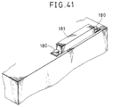
- a cover 141 is fixed to the card insertion slot as shown in Fig 41 through a set of screws 180 in order to prevent the card take-out button from being accidently touched during a use of the dealing board, and foreign matter such as dust and trash from entering or invading into the card insertion slot damaging the reader-writer during a non-use of the dealing board.
- the conventional cover 181 is fixed to over the card insertion slot by means of screws 180, so that it is necessary to remove the screws 180 and the cover 181 every time the dealing board is used. Consequently it is troublesome to remove and fix the screws and the cover. The cover 181 is apt to be missed after the cover is removed from the dealing board main body and accidently let it loose.
- the frontface of the dealing board main body provided with the control panel slanted down in front is slanted rearward as it goes down so as to separate the frontface of the dealing board main body from the legs of the user or prevent the knee of the user from hitting the dealing board main body, as well the top plate of the desk can lengthen.
- a number of dealing boards much more than the prior art can be installed in a single dealing room. It is economical.
- the bottom face of the dealing board main body and the print substrate accomodated in the main body are placed in parallel with the control panel in order to form no space of unnecessary between the bottom plate and the print substrate, and respective print substrates and to raise the mounting space efficiency.
- a fixing member for securing the dealing board main body to the desk has a slant angle so as to control the slant angle of the control panel. Consequently, it is possible to set the angle of the panel according to the desire of the customer without a manufacture of the dealing board main body according to the particular desire of the customer. It is easy to standardize the angle of the panel, and it is not necessary to previously prepare or stock many dealing board main body of plural kinds making the management of the main bodies easy.
- the key unit has a switch mechanism consisting of a contact formed on the print substrate and a conductive contact rubber for turning the contact above ON and OFF, a display element formed so as to correspond with each contact, and a chip element installed between the lower face of the key case and the print substrate, thus it is possible to diminish the gap distance between respective key cases of the key unit and the arrangement pitch of the key unit, lessen the depth or width of the dealing panel miniaturizing the whole construction of the dealing board.
- flat-pack IC parts having function to integrate a number of matrix information using indication elements and switch mechanismes and capable to mount on flat faces are mounted on the opposite side of the face constructing contacts of the print substrate.
- IC parts for controlling the matrix information are divided and mounted on another print substrate. In other words, it is possible to carry out a high density or compact parts mounting on the print substrate and reduce some print substrates and connectors miniatuarizing the panel unit and curtailing the manufacturing cost.
- the dealing board provided with multi-function of telephoning, units uniting these various functions and panels of these units, there are dents opening through their topfaces placed between the panel attached onto the topface of the case so as to incline in front.
- the panel is inserted in the case through the opening of the dent and secured by screws inserted from above.
- the nevel method for securing the panel to the case can make the removal-securing process of the panel easy and control of the gap between panels can be done from above, resulting in a good workability.
- the opening of the dent is closed by a removable cover, omitting an exposure of heads of fastening parts, for example, screws for holding and securing the panel and improving the appearance.
- a sucking member made of magnetic material is fixed to the cover so as to make the cover attracted to other magnet of the case.
- the ninth invention of the application has the cover made of an elastic material so as to simplify the removal-fitting of the cover.
- the tenth invention has a protrusion protruded upwardly from the topface of the panel and formed on the cover, which being formed to prevent writing instruments carelessly placed on the panel from dropping.
- the plurality of panel units containing several functions have protruding engagement pieces formed at ends of the units and one engagement piece is engaged with one end of the opening formed in the topface of the dealing board main body and another engagement piece is inserted into the gap formed at one end of the fixing pieces.
- another end of the fixing piece is removably secured to a screen plate formed near the opening of the dealing board main body through screws.
- a fixing portion for securing the cover to the dealing board main body, a hinge portion functioning as a fulcrum of the opening and closing cover, and a holding mechanism for holding the cover at its erected position or condition, respectively are provided on one end side of the cover.
- an elastic engagement portion for removably engaging with an engagement hole formed on the dealing board main body are provided.
- Covering the card insertion slot and the card take-out button by a cover during a usage of the dealing board prevents the card take-out button from carelessly or erroneously being touched by the user and prevents foreign matter such as dust from entering or invading to the reader-writer during a time of non-use of the dealing board.
- the first purpose of the present inventions resides in a provision of the dealing board contributing to shortening of the top plate of the desk.
- the tenth purpose of the present inventions is to provide a dealing board having no problem of preventing writing instruments placed carelessly on the slanted panel from dropping and preventing the work from being hindered or disturbed.
- the eleventh purpose of the present inventions is to provide a dealing board having panel units which are easy to fix and control.
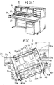
- Fig 1 is a perspective view showing the whole structure of the dealing board concerning the first-third inventions.
- Fig 2 is a section showing the dealing board main body.
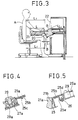
- Fig 3 is a section showing a usage condition of the dealing body.
- Fig 4 is an enlarged view of the portion shown by IV.
- Fig 5 is also an enlarged view of the portion of V.
- Fig 6 is an explanation view showing another embodiment.
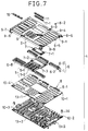
- Fig 7 is an exploded perspective view of the panel units of the dealing board concerning the fourth and the fifth inventions.
- Fig 8 is an exploded perspective view of the constituent parts mounted on the print substrate of the panel unit.
- Fig 9 is a section depicting an important portion of the key unit constituting the panel unit.
- Fig 10 is a perspective view showing a rearface of the print substrate constituting the key unit.
- Fig 11 is a section showing a usage condition of the panel unit.
- Fig 12 is a perspective view of the main body of the dealing board to which the sixth - the tenth inventions relate.
- Fig 13 is a section of the main body in its assembled condition.
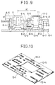
- Fig 14 is an explanation view of operation of the dealing board.
- Fig 15 is also an explanation view of operation of the dealing board.
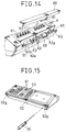
- Fig 16 is an exploded perspective view of another embodiment of the main body of the dealing board.
- Fig 17 is a perspective view of the another embodiment of the dealing board main body.
- Fig 18 is a section of the other embodiment of the dealing board main body.
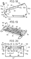
- Fig 19 is a perspective view of the dealing board main body to which the eleventh invention relate.
- Fig 20 is a section of the main body of the same dealing board.
- Fig 21 is an enlarged exploded view of the portion VI in Fig 20.
- Fig 22 is an enlarged exploded view of the portion VII in Fig 20.
- Fig 23 is a perspective view of the dealing board main body.
- Fig 24 is a perspective view of the cover of the main body of the dealing board.
- Fig 25 is a perspective view of the cover of the main body of the same dealing board.
- Fig 26 is a front view seen along the direction VIII shown in Fig 24.
- Fig 27 is an exploded perspective view showing the process of cover fixing.
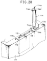
- Fig 28 is a perspective view of the dealing board main body having the cover open.
- Fig 29 is a perspective view of the whole construction of the conventional dealing board.
- Fig 30 is a section of the whole dealing board.
- Fig 31 is a section of the main body of the dealing board above.
- Fig 32 is a section of the main body of the dealing board main body.
- Fig 33 is an explanation view of the dealing board main body at its usage condition.
- Fig 34 is a plane view of a panel unit on the main body of the dealing board.
- Fig 35 is a front view of the panel unit.
- Fig 36 is a side elevation of the panel unit.
- Fig 37 is a perspective view of the panel unit.
- Fig 38 is a section of the important portion of the key unit of the panel unit.
- Fig 39 is a section of the main body of the dealing board.
- Fig 40 is a section of the main body of another dealing board.
- Fig 41 is a perspective view of the cover on the main body of the conventional dealing board.
- the dealing board of the present invention consists of a main body 20, a desk 21, a display 22 displaying economy information, a hand-set 23, and a microphone 24.
- the dealing board main body 20 has a box-like case 25, as shown in Fig 2, and the case 25 has a control panel 25a fixed to the topface of the case.
- a bottom face 25h of the case 25 is in parallel with the control panel 25a and the front face 25f and the rear face 25g of the case 25 is at a right angle to the control panel 25a.
- the upper print substrate 27 has a function button 29 exposed from the control panel 25a, as well as a spacer 30 is placed between respective print substrates 27 and 28. These print substrates 27 and 28 are fixed on the rear face of the control panel 25a so as to be in parallel to each other. A pair of connectors 31a and 31b joins electrically the upper print substrate 27 to the lower one 28.
- the function button 29 installed on the upper print substrate 27 has a conductive contact rubber 29a (see Fig 4) at its lower end. Pushing down the function button 29 makes the conductive contact rubber 29a contact the contact 27a formed on the print substrate 27 so as to carry out ON-OFF operation of the circuit.
- the lower print substrate 44 is installed in the bottom space so as to be in parallel with the bottom face 25h of the case 25 through a set of spacers 35. While, the upper print substrate 34 is placed above the lower print substrate 44 in parallel with the print substrate 44 through a set of other spaces 36.
- the other upper or top print substrate 33 is connected to the upper print substrate 34 securely by connectors 45a and 45b. Both the print substrates 33 and 44 are electrically connected to each other by a system of the connector 33a, a signal cable 38a, and the other connector 34a.
- top plate 21a of the desk 21 on which the dealing board main body 20 is mounted has an open portion 21b open a little larger than the area of the dealing board main body 20.
- fixtures 40 and 41 are secured on the lower face of the open portion 21b.
- the fixture 40 installed at the front side of the open portion 21b is longer than that at the rear side of the open portion 21b. Both upper end portions of the fixtures 40 and 41 are secured to the lower face of the top plate 21a by small screws 42.
- the lower portion of the front fixture 40 is rearward slanted and has a lowest L-shape end portion or engagement portion 40a.
- the other rear fixture 41 has a main portion extending in a right angle to the top plate 21a and a top end portion extending from the main portion at a right angle and being secured to a bottom face of the top plate 21 by a small screw 42 as described above.
- the fixture 41 has a bottom or lowest engagement portion 41a extending slantly and downward and an angle adjusting screw 43 is inserted from the below through the lowest engagement portion 41a.
- the bottom face 25h of the case 25 of the dealing board main body 20 inserted from above through the open portion 21b of the desk 21 is supported from the bottom by a front end of the angle adjusting screw 43 and the engagement portion 40a of the fixture 40 so as to slant to the front the control panel 25a relative to the upper face of the top plate 21a of the desk 21.
- the fixing angle of the front fixture 40 is set so as to make the slanting angle ⁇ of the control panel 25a about 20° degree.
- a slanting distance L1 of the bottom face of the dealing board main body 20 becomes about 68 mm. The distance is sufficient to general users, so that even the length L of the top plate is made short, the knee B of the user A hardly hit the main body 20 resulting in a small size of the desk 21.
- print substrates 33, 34, and 44 are fixed in the bottom space of the main body 20 in parallel with the top face of the control panel and the case 25 is installed slantly, these print substrates 33, 34, and 44 are slanted, so that heat stream 48 shown by an arrow in Fig 2 flows along these print substrates 33, 34, and 34 effectively radiating heat generated from the various electronic parts mounted thereon.
- the engagement piece 25c and the fixing piece 25d are secured to the control panel 25a through for example a welding method, however they may be formed by a molding process of resin.
- the control panel 25a, the case 25, and the fixing piece 25e at the case side may be molded.
- the front and the rear walls 25f and 25g of the case 25 are formed so as to be at a right angle to the plane of the control panel 25a, however it is not necessary to form these walls and right and left walls (not shown) of the case 25 at a right angle to the control panel 25a on condition that at least the bottom face 25h is in parallel to the control panel 25a.
- These walls may be arranged in a shape of diamond seeing from right or left side of the case 25.
- FIG 6 shows another embodiment of the present invention in which embodiment the desk 21 has a display stand 46 placed on its rear space, which stand being slanted by a predetermined angle and on which stand the dealing board main body 20 is placed.
- the control panel 25a of the case 25 is slanted and there is no necessary to form the open portion 21b in the top plate 21a of the desk 21, using the top plate of the desk 21 effectively.
- the front face of the dealing board main body having the forward-slanted control panel is slanted rearward or backed horizontally the more distance the portion of the case wall lowers, the front face of the dealing board main body is separated from the user's knee and consequently the top plate of the disk can be shorten. It is economy because number of the dealing board to be installed in a particular dealing room can be increased.
- the bottom face of the dealing board main body and the print substrates contained in the main body are placed in parallel with the control panel, so that no useless space is generated between the bottom plate and the print substrates, and respective print substrates improving element mounting space efficiency.
- the dealing board has a fixing member for slantly securing the main body of the dealing board to the desk in order to adjust freely the slanting angle of the control panel on the main body, so that it is possible to set the angle of the control panel according to demands of the customer and to standardize the dealing board main body. It is not necessary to manufacture these dealing board main body according to the client and to prepare previously the main bodies of several kinds, simplifying a management of the main bodies.
- Fig 7 is an exploded perspective view of the panel unit or control panel of the embodiment above and Fig 8 is an exploded perspective view of the constituent parts or elements to be mounted on the print substrate of the embodiment above.
- a panel 9 has a set of openings 9-1 on which key units 6 having automatic dialing functions are mounted and another set of openings 9-2 on which a dialing portion 5 is mounted. These sets are arranged in plural rows and plural lines.
- the panel 9 has an opening portion 9-3 on which a display 7 is mounted, and an opening portion 9-4 on which a volume 8 of various displays 7 is mounted. If necessary, it is possible to place the opening portion 9-4 for the volume control 8 under the panel 9 or between the openings 9-1 and 9-2 formed in line.
- a plurality of fixing devices 9-5 having femal screws securing the print substrate 10-1 are formed at suitable positions of the bottom face.
- upper and lower end faces of the panel 9 are bent in a L-shape of section.
- engagement claws 9-6 having respectively fixing holes 9-7.
- the dialing portion 5 consists of dialing buttons 5-1 and a dialing button case 5-2 for slidably holding the buttons.
- the key case 6-1 constituting a key control portion of the key unit 6 has a through hole 6-3 through which a key button 11 slides (Fig 9) and a lens insertion hole 6-2 for holding LED (Light Emitting Diode) lenses 6-4 and 6-5 and the like.
- the key button 11 is fitted into the through hole 6-3 formed in the key case 6-1 and the key button 11 is prevented from falling off by means of a claw 11-1 formed on the key button 11.
- LDC transparent liquid crystal device
- a volume control 8-1 operable through a volume button 8-2 is placed at the predetermined position on the print substrate 10-1, and key buttons 11 of the key unit 6 and dialing buttons 5-1 of a dial control portion 5 are installed on the print substrate 10-1 so as to form a circuit.
- flat packs IC 10-5 capable to be mounted on flat surfaces are mounted on the opposite side of the contact constituting face.
- the flat pack IC 10-5 has functions of integrating matrix information of a number of switches and LEDs. The integrated information is transferred to the print substrate 10-2 through connectors 13-1, 13-2 and the integrated information is treated by ICs and the like mounted on the print substrate 10-2.
- print substrates 10-1 and 10-2 are secured to the panel 9 through a set of fixing holes 10-3, 10-4 and bushings 14, so that the key unit 6 and the dial control portion 5 are installed on the panel 9 constituting a panel unit 4.
- the print substrate 10-1 has a set of contacts 10-6, 10-7 corresponding to the dial control portion 5 and the key unit 6.
- These contacts 10-6, 10-7 are formed by printing conductive carbon paste. It is possible to form the contacts with metallic material through a welding process.
- Conductive contact rubbers 5-3, 6-3 are used in a switch mechanism for turning these contacts 10-6 and 10-7 ON-OFF.
- a LED chip 12-2 is mounted on the print substrate 10-1 so as to function as a fisplay element corresponding to the contact 10-6.
- the conductive contact rubber 6-3 has an open portion 6-6 through which the LED chip 12-2 protrudes (Figs 8 and 9).
- the key case 6-1 of the key unit 6 is installed downward, the LED lens 6-5 is inserted through a lens insertion hole 6-2, a LED lens 6-4 is placed on the LED lens 6-5, the conductive contact rubber 6-3 is placed on the open portion 6-8 formed in the key case 6-1, and a guide hole 6-10 for guiding the conductive contact rubber 6-3 is applied to a protruded portion (not shown) formed in the key case 6-1, so that the conductive contact rubber 6-3 is placed in place (Fig 9).
- the conductive contact rubber 5-3 is placed in place by the facts that the dial button case 5-2 of the dial control portion 5 is downward installed similar to the key case 6 of the key unit 6, a dial button 5-1 is installed on the dial button case 5-2 so as to make a character of the dial button 5-1 face downward, the conductive contact rubber 5-3 is installed on the dial button case 5-2 so as to face a contact portion of the conductive contact rubber 5-3 upward, and the guide hole 5-4 formed in the conductive contact rubber 5-3, similar to that of the key unit 6, is inserted into the protrusion portion (not shown) formed on the dial button case 5-2.
- the key unit 6 and the dial control portion 5 respectively constructed as described above are installed downward in respective open portions 9-1 and 9-2 of the panel 9 facing downward. It is noted that the display 7 of the LCD and the like are previously secured to the panel 9.
- the print substrate 10-1 is mounted on the panel 9 so as to face respective contacts 10-6 and 10-7 down to the key unit 6 and the dial control portion 5 installed in the panel 9, as well as the fixing hole 10-4 of the print substrate 10-1 is aligned with the hole of the fixing device 9-5 of the panel 9, the print substrate 10-2 is placed on the bushing 14 so as to be aligned the bushing 14 with the holes of the print substrate 10-1 and the panel 9, then they are fastened by a screw in order to construct the panel unit 4.
- Fig 9 is the section of the important portion of the key unit constructing the panel unit of the present invention.
- the contact 10-6 on which conductive carbon paste is printed is formed on the print substrate 10-1.
- LED chip 12-2 placed so as to correspond with the contact 10-6, and LED lenses 6-4 and 6-5 are installed on the LED chip 12-2.
- the LED lens 6-4 roles to transfer effectively upward light beam generated from the LED chip 12-2 and also the LED lens 6-4 enlarges an area of light beam.
- the LED lens 6-5 is made to have, for example, a width of 1 mm, a half of the conventional width of 2 mm, so that the LED lens 6-5 can be placed adjacent to the key button 11 by 1 mm. Because that the width of the LED lens 6-5 is 1 mm, it is necessary to make the length twice comparing to that of the prior art in order to improve easiness to see light from the LED chip 12-2, so that the length of the LED chip is made 10 mm.
- the user of the dealing board 1 When the user of the dealing board 1 is going to carry out a transmission with the customer, the user once pushes the key button 11 indicating the name of the customer and the telephone line is connected to the customer with a button-touch, emitting light from the LED chip 12-2.
- the telephone line is being used, however when another customer or caller is calling on the same line, it is indicated by the LED chip.
- the colors of the cases of being called and calling are differed from each other. According to the present invention, it is possible that one LED chip 12-2 emits three colors at most.
- the conductive contact rubber 6-3 placed under the key button 11 corresponds to the contact 10-6 placed in the print substrate 10-1 and the conduct rubber 6-3 is not covered by a case as that of the conventional key switch. Consequently, it is possible to make the conductive contact rubber 6-3 turned ON-OFF with the contact 10-6 on the print substrate 10-1.
- the width of the frame 9-8 between openings 9-1, through which the key unit 6 formed in the panel 9 is accomodated is made narrow exceedingly from 5 mm of the prior art to 2.8 mm, so that it is possible to lessen the pitches between the key units 6.
- the depth of the key button 11 is made 10.7 mm which is the same as that of the prior art.
- the panel 9 is manufactured by a sheet metal processing according to the embodiment, but it is possible to manufacture it by a mold process.
- the key case 6-1 of the key unit 6, the dial button 5-1 of the dial control portion 5, and the key button 11 are formed by a mold process.
- the key unit 6 may have two sliding portions of the key button and may be constructed to accomodate a long button having a size about twice of the length of the key button 11.
- Such long button is used, for example, to reserve the telephone line, transfer and off-operation of the telephone, which are functions used repeatedly. Because the key button is long, an operability thereof will be improved.
- the key unit has a switch mechanism consisting of contacts formed on the print substrate and a conductive contact rubber used to turn the contact ON-OFF, and display elements corresponding to each contact.
- a chip element is installed between the bottom face of the key case and the print substrate, so that it is possible to shorten the distance or pitch X1 between the key cases 6-1 of the key unit reducing the depth or width of the panel unit. As a result, a small dealing board having a wide working space of the dealing desk is attained.
- a number of matrix information of the switch mechanism and the display elements are integrated on the opposite side of the face on which contacts of the print substrate are formed, the flat pack IC parts enabling to be mounted on surfaces are mounted, and IC parts for controlling the matrix information are divided and mounted on the other print substrate, so that it is possible to carry out a high density parts mounting on the print substrate and a miniaturizing and cost-reduction of the panel unit by a reduction of the number of the print substrates and joining connectors therefor.
- FIG. 12 - 18 Another embodiment of the fixing structure securing a panel unit to the opening or open portion of the dealing board main body is shown in Figs 12 - 18.
- Fig 12 shows a whole view of the dealing board having multi-telephone functions
- Fig 13 is a section depicting an assembled case
- Figs 14 and 15 are operation explanation views of disassembling process of the case.
- the main body 51 of the dealing board has a case 52 provided with an open top face and a plurality of panels 53 are detachably secured to the opening 52a of the case 52.
- Fig 12 shows a hand set of the telephone set and 55 is a microphone.
- the case 52 of the dealing board main body 51 has a rear wall 52c higher than its front wall 52b so as to slant forward the top face of the case.
- a bottom plate 52d is detachably secured to the bottom portion by a small screw 56.
- a fixing piece 52e is firmly secured to the open edge of the rear side of the opening 52a at the top face of the case 52, and a receiving member 57 in a shape of L in section substantially is secured to the front open edge by a welding or the like.
- a securing member 62 formed by bending in a shape substantially of a crank in section is secured through its one side to the rear face of the front edge side of the panel 53 by means of a welding or the like.
- the other side of the securing member 62 is adapted to be mounted on the receiving member 57 at the side of the case 52 as shown in Fig 14 when the panel 53 fits into the opening 52a from above, so that there is a bis hole 62a there. It is possible to secure the panel 53 to the case 52 by inserting threadly the bis or small screw 63 inserted through the bis hole 62a formed in the securing member 62.
- the securing member 62b shown in the figure is a cut-out formed in the securing member 62.
- the cover 66 is adapted to be fitted from above into the upper opening of the dent 65.
- the cover 66 has a section of a shape of substantially L and a size sufficient to cover the opening of the dent 65.
- a sucking member 67 made of magnetic material is fixed to the lower face of the central portion of the cover 66. When the cover 66 fits into the opening of the dent 65 from above, the sucking member 67 is sucked by a magnet 68 fixed to the receiving member 57 at the side of the case 52, so it is possible to place the cover 66 on the case 52.
- FIG 52 in the figure means a cut-out through which a tool such as a driver 70 is inserted when the cover 66 is intended to remove (Fig 15).
- a gap between panels 53 is adjusted so as to make the gaps X between panels 53 equal and the securing member 62 is secured to the receiving member 57 by a small screw 63.
- the cover 66 fits into the opening of the dent 65 to close the opening.
- the dent 65 is formed at the front side of the case 52, it is possible alternately to form dents 65 at the front and the rear sides of the case 52, front and rear portions of the panel 53 are fixed to the case 52 through the small screws 63 as shown in Fig 16, and covers 66 fit into the front and rear dents 65 as shown in Fig 17.
- Fig 18 shows still another embodiment in which an opening 65a of the dent 65 expands fully across substantially the width of the top face of the case 52 and an elastic member 71 is fitted to the opening 65a so as to make a top portion of the elastic member 71 protrude above the top face of the panel 53.
- the elastic member 71 when the elastic member 71 is taken off from the opening 65a of the dent 65, the small screw 63 is exposed, so that it is possible to fix and remove the panel 53 from above the case 52 similar to the previous embodiment. Furthermore, when the dealing board is used, the top portion of the elastic member 71 protrudes above the panel 53, so that a writing instrument 72 placed carelessly on the panel 53 is stopped by a protrusion 71a of the top portion of the elastic member 71, preventing the writing instrument 72 from dropping.
- the prevention function above can be also attained by forming a protrusion on the cover 66.
- the case 52 and the panel 53 are manufactured by a metal plate forming process, however they can be formed by molding resin and the like, in which case it is possible to form the fixing pieces 52e and 53a, receiving member 57, and securing member 62 integrally with the case 52 and panel 53.
- the sixth invention of the present application provides a dealing board having a multiple telephoning functions which are unitized and respective units are panelarized, and a plurality of panels are installed therein.
- a dent having an open top face opening between respective panels installed so as to be slant forward is formed on the top face of the case and the panel is adapted to be secured to the case from above through the opening of the dent by means of a screw, consequently it is not necessary to turn over the case in order to secure the panel according to the prior art, so that the detaching work of the panels can be done without difficulty, as well as the gap between panels can be done from above the case, improving its workability.
- the opening of the dent is adapted to be closed by a removable cover, so that no fastening means such as screws for the panel is need and no means is exposed, resulting in an improvement of appearance.
- a sucking member made of magnetic material is installed on the cover, which sucking member is adapted to be sucked to the magnet on the case, resulting in easy removement of the cover.
- the cover is made of elastic member and so removal of the cover is made easy.
- the cover has a protrusion protruded above the top face of the panel, and even though a writing instrument is carelessly placed on the panel, the protrusion prevents the instrment from falling down and solves any hiderance on work.
- Fig 19 is a perspective view of a single dealing board and Fig 20 is a section of the dealing board.
- the dealing board shown in Fig 19 provides with a main body 81 installed on the desk so as to be slanted on this or front side and a plurality of panel units 82 are arranged transversely in row on the opening 81a opening in the top face of the dealing board main body 81.
- a plurality of panel units 82 are arranged transversely in row on the opening 81a opening in the top face of the dealing board main body 81.
- hand-sets 83 and 84 for calling and receiving calls through two-wire lines.
- While the panel unit 82 has united telephoning functions, and a dial button 90 for calling the clients, a liquid crystal display portion 91 displaying messages and the like, and one-push button 92 for enabling to call the customer instantly are panel-unitted per each function.
- the front edge 81b of the opening 81a open in the top face of the dealing board main body 81 is substantially at a right angle to a front face plate 81c of the dealing board main body 81.
- a receiving device 81d shaped in substantially a reversed L is secured to the inside of the front edge 81b so as to left a gap X3 between the front edge 81b and the lower face, and an engagement piece 82a protruding from the panel unit 82 is adapted to be inserted into the gap X3 between the receiving device 81d and the front edge 81b.
- the panel unit 82 having an auto-dial function enabling to call the particular customer by instantly or one-push operation has the following structure.
- a case 92a of the one touch button 92 is accommodated in the opening 82c open in the panel 82b 0f the panel unit 82 and a button 92b is installed slidably up-and-down within the case 92a.
- a conductive contact rubber 92c and the print substrate 94 are placed with a gap between them.
- the conductive contact rubber 92c is adapted to contact the contact 94a on the print substrate 94 generating an ON signal when the button 92b is pushed.
- the print substrate 94 as shown in Fig 20 is secured to a rear face of the panel 82b through a spacer 95 and a set-screw 96 and another print substrate 97 is secured to below the print substrate 94 through the spacer 95 and the set-screw 96.
- Electronic part 98 for obtaining one-touch dialing function is secured to the print substrate 97 and a connector 99 joints one of print substrates 94 and 97 to another one.
- An engagement piece 82a is protrudingly formed at the front end and the rear end of the panel 82b of the panel unit 82 mentioned above and the engagement piece 82a at the front end is engaged with the opening 81a at the side of the front edge 81b.
- the engagement piece 82a at the rear end side is adapted to be secured to the dealing board main body 81 by means of a fixing device 100 formed at a rear edge of the opening 81a of the dealing board main body 81.
- the fixing device 100 has a substantial reversed L-shape and another fixing device 100a of a reversed L-shape smaller than the former is secured to within an interior of the former through a gap X3'.
- a size of the gap X3' is sufficient to make the engagement piece 82a inserted therethrough, similar to the previous gap X3.
- a front end of the receiving device 100a is adapted to not protrude from a front end of the fixing device 100.
- the fixing device 100 has a thread hole 100b formed therein through which hole 100b a set-screw 101 is inserted, which set-screw is adapted to be threadly inserted through a screen plate or partition plate 81e secured to a rear face plate 81g of the dealing board main body 81.
- the screen plate 81e is secured to the inside of an upper edge portion of the rear face plate 81g by means of a means such as a welding as shown in Fig 21.
- a screw hole 81f through which the set-screw 101 is inserted is formed at a top end side of the screen plate 81e.
- the engagement piece 82a at the front end side of the panel unit 82 is inserted through the gap X3 formed between the front edge 81b of the opening 81a and the receiving device 81d, then another engagement piece 82a at a rear end side is inserted through another gap X3 between the fixing device 100 and the receiving device 100a, a set-screw 101 inserted through a screw hole 100b of the fixing device 100 is threadedly inserted through a screw hole 81f of a screen plate 81e, tentatively holding the panel unit 82.
- the gap X1 between the dealing board main body 81 and each panel unit 82 and another gap X2 (not shown) between respective panel units 82 are adjusted so as to equalize them to each other and then set-screws 101 are finally fastened in order to settle all panel units 82 relative to the dealing board main body 81. Consequently it is not necessary to turn round or reverse the dealing board main body 81, as until recently done, when the panel units 82 are secured to the main body 81.
- the fixing device 100 is placed at the side of the rear face plate 81g of the main body 81 of the dealing board, however it is apparent that it may be installed at the side of the front face plate 81c.
- the fixing device 100 is made of metal sheet, so its surface is preferably painted.
- the gaps X3, X3' through which engagement piece 82a is inserted are determined as shown below.
- the thickness of the engagement piece 82a is 1.6 mm.
- the gaps X3, X3' are determined to 1.8 mm and the engagement piece 82a is inserted through the gaps X3, X3', the paint will be peeled off.
- the engagement piece 82a When the gaps are fixed to 2.2 mm, the engagement piece 82a enters without difficulty, however the piece 82a will be given a play. It is not preferable. As a result, the gaps X3, X3' are determined 2.0 mm. The engagement piece 82a becomes able to insert through the gaps X3, X3' without peeling off of paint.
- the data above is obtained when the fixing device 100 is manufactured by metal sheet.
- the fixing device 100 is manufactured by synthetic resin, no problem of paint peeling will happen.
- the manufacturing process may be applied to electric appliances and machines other than the dealing board with a similar result.
- one of the engagement piece protruded from both ends of the panel unit is engaged with an end of the opening of the dealing board main body and another engagement piece is secured to the dealing board main body by a fixing device on the front surface or near the front surface of the main body, so that it is possible to secure panel units without reversing the dealing board main body, as well as to adjust the gaps between respective panel units while seeing the surface of the dealing board main body.
- a fixing device on the front surface or near the front surface of the main body
- panel units are effectively secured for short times.
- checking and repairing of the panel units can be done at the front surface of the main body of the dealing board, resulting in easiness of exchanging and maintenance of the panel units.
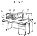
- Fig 23 shows a perspective view of the dealing board provided with a control panel 112 placed on the top face of a main body 111 of the dealing board shown, a plasma display 113, a reader-writer (not shown), and a card insertion slot 116.
- the control panel 112 has a number of buttons 112a and the card insertion slot 116 is adapted to be covered with a cover 114 and through which a memory card 115 is inserted.
- the card insertion slot 116 has an ellipse opening and a protrusion button 118 for taking out the card is placed by one end of the card insertion slot 116.
- a fixing hole 111a and a small hole 111b adjacent to the button 118 through the former a fastening device 125 such as a rivet fastening one end portion of the cover 114 is inserted and through the latter a projection 114 for preventing the cover 114 from rotating is inserted.
- an engagement hole 111c of a raised-type shape in plane Adjacent to the other end of the card insertion slot 116, an engagement hole 111c of a raised-type shape in plane is formed, and the hole 111c has an engagement portion 111d.
- cover 114 is integrally formed by synthetic resin and the like and it consists of generally a flat portion 114b covering the card insertion slot 116 and a raised button cover portion 114c covering the card taking-out button 118 as shown in Figs 24-26.
- An elastic engagement claw 114d of an elastic engagement portion having a substantial V-shape in side view is integrally formed at an end portion of the flat plate portion 114b.
- the elastic engagement claw 114d has a narrow engagement portion 114d' and a knob 114e for taking off the narrow engagement portion 114d' which are adapted to be engageable with an engagement portion 111d of the engagement hole 111c.
- the button covering portion 114c has an open bottom.
- the card taking-off button 118 protrudes through the open button and accomodated in the button covering portion 114c.
- Two slits 114f extending along an up-and-down direction are formed with a separation gap of a width direction between them at the end face of the button covering portion 114c.
- a fixing portion 114l of a tongue-shape is integrally formed below the end face side of the button covering portion 114c.
- a hinge portion 114k In order to make a hinge portion 114k elastically deformable, it has a cut-out 114m formed on the end face of the button cover portion 114c so as to sandwich the hinge portion 114k, as well as the hinge portion 114k itself has a thickness, for example, about 0.3 - 0.5 mm thinner than that of the fixing portion 114l.
- the fixing portion 114l has a fixing hole 114n formed at a position corresponding to that of another fixing hole 111a open at the side of the main body 111 of the dealing board, and a protrusion 114a placed at a position corresponding to a small hole 111b so as to prevent the cover 114 from rotating.
- the cover 114 is placed by the following process. As shown in Fig 27, the fastening device or rivet 125 is inserted through the fixing hole 111a of the dealing board main body 111 and another fixing hole 114n formed in the fixing portion 114l, and then the fastening device 126 is calked. In the fastening process, the projection 114a formed on the bottom face of the fixing portion 114l fits the small hole 111b at the side of the dealing board main body 111, thus the cover 114 is prevented from rotating around a fulcrum of the fastening device 125.
- the knob 114e at a front end of the elastic engagement claw 114d is pushed so as to make the gap X4 at its front end narrow, taking off the engagement portion 111d from another engagement portion 114d.
- the cover 114 When the cover 114 is raised upward about a right angle around the hinge portion 114k, the front ends of the engagement piece 114g protruded along both side directions of the fixing portion 114l enter in the slits 114f through the end face of the button cover portion 114c, the engagement portion 114h formed protrudingly at front ends of the engagement piece 114g rides over the ridges 114i formed on the inner walls of the slits 114f. As a result, the cover 114 can be held in an erected position for oneself because the engagement portion 114h engages with the ridges 114i.
- the memory card 115 is inserted through the card insertion slot 116 and the cover 114 is closed, so the card taking-out button 118 is covered by the cover 114, resulting in a prevention of the card taking-out button 118 from errorneously being touched during an usage of the dealing board.
- the cover 114 is formed in a shape of flat plate in part in order to miniaturize the cover 114, however it is possible to make the cover 114 of a square box of a size enough to cover the card insertion slot 116 and the card taking-out button 118.
- the cover 114 may be made of transparent or semi-transparent material.
- the cover As described in detail above, according to the twelveth invention of the present application, as for a construction of the cover for covering the card insertion slot of the reader-writer for reading and writing information stored in the memory card, and covering the card taking-out button placed adjacent to the card insertion slot, the cover has, at its end, a fixing portion for installing the cover on the dealing board main body, a hinge portion functioned as a fulcrum of opening and closing the cover, and a holding mechanism for holding the cover in its erected postion after it is raised around the hinge portion.
- the cover has at its other end an elastic engagement portion adapted to engage removably with an engagement hole formed in the dealing board main body, thereby it is possible to prevent the card taking-out button from errorneously and carelessly being touched, and foreign matter such as dust and trash from entering and invading into the card insertion slot. In consequence, it is possible to prevent the reader-writer from malfunctioning and damaging due to foreign matter.
- the cover can open around the hinge portion after only a taking-off of the elastic engagement portion, it is extremely easy to open and close the cover more than that of the prior art cover which being open by loosening screws. In addition, the cover is not detached from the dealing board main body, so there is no afraid of missing the cover.
- the open cover is hold at its erected postion substantially perpendicularly, the cover doesn't hinder the memory card to be entered and taken out.
Abstract
Description
- The present invention relates to a dealing board provided with various telephoning functions and adapted to be used as a terminal of a financial institution, such as banks and securities corporations.
- Generally speaking, the dealing board used as a financial terminal has a telephone function, however with it has become of a wide variety recently, several functions of the terminal are grouped and panellarized in units. Customers can select their necessary units other than basic units and combine these selected units in order to construct the particular and custom-built dealing board.
- Because the dealing board has telephone functions, it is constructed by a hand-set, a set of dialing buttons, function buttons, a display, a microphone, a speaker, and a set of switches operating and controlling these instruments above.
- Figs 29 and 30, respectively show perspective views of the conventional dealing board of the kind above.
- As shown, a
main body 131 of the dealing board is installed on adesk 132. Adisplay system 133 displaying information on economy is installed on the front portion of thedesk 132 and acontrol box 134 is placed under the desk. - Ordinarily, a
control panel 139a of themain body 131 of the dealing board is apt to be declined by an angle of range of 10° - 30° in order to make the operability of the dealing board good. - As shown in Figs 31 and 32, the
main body 131 of the dealing board consists of thecontrol panel 139a, thefunction buttons 135, a pair ofprint substrates case 139 containing these parts above. Theseprint substrates bushings 140 and the assembled is installed on the inner face of the front-declinedcontrol panel 139a by screws 141. - A plurality of stepes or floors of
junction print substrate 142 joining the dealing boardmain body 131 to thecontrol box 134, and the set ofprint substrates 143 and 144 is contained and installed on the bottom portion of thecase 139. - According to the conventional dealing board shown, the
control panel 139a is installed on the upper face of the box-like case 139 so as to be inclined down toward the front, thebottom face 139d of thecase 139 is placed horizontally, and the front and therear faces case 139 are situated at a right angle relative to thebottom face 139d. - In order to assemble the conventional dealing board, the
case 139 of the dealing boardmain body 131 is inserted downward through anopening portion 132a of thedesk 132 and thecase 139 is fixed in place by a set offixtures 145. In such situation, a pair of vertical walls of thecase 139 is placed at a right angle to the top plate of thedesk 132, so when a user A sits on a chair in back of the dealing board, his knee B touches thefront face 139b or a corner of the case as shwon in Fig 33 blocking up free movement of the knee B of the user, as well the person cannot sit on the chair comfortably creating early fatigure of the user disadvantageously. - It is possible, as apparent from Figs 30 and 33, to lengthen the length L of the top plate of the
desk 132. However, a lengthening of the top plate above generates inconveniently alarge desk 132 occupying disadvantageously a large space of the office room when the dealing board with the large-size desk is installed therein. - Also, the
main body 131 of the conventional dealing board has slantedprint substrates function buttons 135 are mounted andother print substrates case 139 are placed in horizontal posture, whereby useless space H is created between the set ofprint substrates print substrates case 139 becomes large, and heat generated from electronic parts mounted on thehorizontal print substrates lower print substrates 143 and 144 and escapes through thermal stream 146, resulting in a bad heat radiation of themain body 131 of the dealing board. - In addition, the appropriate declining angle θ of the dealing board varies according to the particular customer of the borad, so that it has been necessary to manufacture the
main body 131 of the dealing board having various declining angle θ according to the particular desire of the user. That is, it is difficult to standarize the angle and a number of kinds of the main body or the dealing board must be produced, resulting in a difficulty of management for the productions of the board. - Still, the conventional dealing board has as shown in Figs 34 - 37 a
panel unit 154 adapted to be used by the user as communication means, which unit includes adial operation part 155, adisplay portion 157 of such as liquid crystal, a number ofkey units 156 having automatic dialing functions, avolume 158 for controlling the volume or darkness or brightness of the microphone and other key units and thedisplay 157, and other control panels for various switches. These various parts contained in thepanel unit 154 are arranged on apanel 159 and connected and secured to print substrates 160-1 and 160-2. The control panel of the dealing board is constructed by the parts of thepanel unit 154 including a hand-set. Further, the dealing board deals with in function a number of clients or business connections and the particular client can be called out with a single touch operation of buttons through the automatic dialing function. The automatic dialing function includes a display function depicting the name or symbol of the customer through a set of light emitting diodes in order to indicate the customer called out, which display function being placed near thekey unit 156 of the automatic dial, and other function indicating an arrival of a telephone call or an existence of a caller. - The names of customers can be memorized in the dealing board by the dialing function, but it is necessary to install on the board of the
panel unit 154 consisting of a number of key switches. It is preferable to construct the control panel of the dealing board by thepanel unit 154 unitizing or grouping various functions in their kinds, because the dealing board has a number of functions. Consequently, the dealing board is constructed by selecting and combining function units, such as adisplay 113 and the like shown in Fig 23, necessary to the customer except the basic function unit. - In general, the conventional dealing board is mounted on the desk and a number of desks having the dealing boards mounted thereon are placed in an office room.
- By the way, the desk with the dealing board has a display apparatus for selecting and displaying various economy information, book shelves and drawers. It is apparent that consequently a predetermined space of the desk top board is necessary to make operation of the dealing board easy and convenient. However, it is need to restrict the size of the desk in order to make many desks accommodated in the dealing room. When the size of the desk is limitted, it is necessary to shorten the depth of the desk obtaining small desks.
- However, apparently the dealing board is constructed by a
panel unit 154 as described above having multi-function. Concerning thepanel unit 154, for example thekey switch 165 shown in Fig 38 of thekey unit 156 with automatic dialing function has an electric conductive contact rubber 165-2 used as a movable contact and a stable contact 165-3, which contact rubber being covered by a case 165-1 and stable contact being fixed on the top face of the case 165-1. In addition, a terminal 165-4 connected to the stable contact 165-3 is soldered to be fixed to the print substrate 160-1. In consequence, due to the existence of the terminal 165-4 protruding from the rear face of the print substrate 160-1, it is difficult to mount other elements or parts on the rear face of the print substrate 160-1, resulting in an impossibility of high density or compact mounting of elements on the print substrate 160-1. Additionally, because that the conductive contact rubber 165-2 is covered by the case 165-1 and constructs thekey switch 165, an area occupied by thekey switch 165 becomes large making a miniaturizing thepanel unit 154 difficult. - Then a protective resistor 162-1 must be arranged on the outside of the
key switch 165 causing hindrance to a miniaturization of thepanel unit 154. - According to the prior art, the
panel unit 154 has been fixed to an opening portion of the main body of the dealing board by the method shown in Fig 39. - That is, by installing a
fixing piece 171 and afixture 172 are applied to the opening portion of thecase 170, and anotherfixing piece 175 engaging with thefixing piece 171 and anotherfixture 177 contacting with thefixture 172 covering thefixture 172 are installed at the side of thepanel 173 so as to engage thefixing piece 175 at the side of thepanel 173 with thefixing piece 171 at the side of thecase 170.Screws 179 placed in thefixtures tool 178, such as a driver, inserted through the bottom portion of thecase 170 after thefixture 177 at the side of thepanel 173 is mounted on thefixture 172 at the side of thecase 170. Thus, thepanel 173 is secured to thecase 170. - According to the fixing mechanism of the prior art as shown in Fig 40, the
panel 173 is fixed to the opening portion of thecase 170 by securing thefixing piece 171 to the opening portion and driving thescrew 179 to fasten thepanel 173 fitted in the opening portion from the top to thefixing piece 171. - The
reference numeral 173a shown indicates function buttons placed in thepanel 173. - It is necessary to turn over the
case 170 when thetool 178 is inserted from the bottom of thecase 170 of the fixing arrangement shown in Fig 39 and used to fasten thescrew 179. - However, the
case 170 has a plurality ofpanels 173 neatly arranged and secured thereto and the gap betweenpanels 173 is adjusted neatly to the fixed distance obtaining a good appearance. Consequently, when thecase 170 must turn over as mentioned above and thepanels 173 are secured thereto, it is necessary to turn over thecase 170 and exchangeseveral panels 173 every time it is intended to change the combination of thepanels 173. When it is found that the gaps between the panels are not equal after the exchange, thecase 170 must be again turned over and repeats the same work. It is explicitly troublesome and time-consuming. - When other fixing construction shown in Fig 40 is employed, in which construction the
panel 173 is secured to thecase 170 by means of thescrew 179 inserted from above thepanel 173, a head of thescrew 179 is exposed deteriorating an appearance of thecase 170. - In general, the control panel of the dealing board main board is declined downwardly in order to develop an operability of the control panel and there is no space, pencils or other writing instruments and the like are held thereon, on the
panel 173, so that when a pencil of writing instrument carelessly is putted on theslanted panel 173, the instrument will roll down from the panel and be missed hindering a smooth working. - The conventional dealing board generally used as a financial terminal deals with transactions of bonds, foreign exchanges, and stocks through telephone lines, so some telephoning functions are installed on the board.
- The telephoning function has an one-touch or one-switching function for calling a customer instantly or by one-pushing. However, because recently a number of the customers has increased due to a variability of the business, it has been difficult to adapt the one-switching operation system to all customers.
- Consequently according to the recent trend, a plasma display is mounted on the dealing board, which display displays the names of customers and telephone numbers. Only touching the particular name by a finger can call out the customer.
- There are other kinds of dealing boards having expanded functions. According to the developped one, name and telephone numbers of the customers are previously memorized in a memory card and the memory card is inserted in an insertion slot of the dealing board, so that the content of the card is displayed on the plasma display. Using the dealing board of the kind above, the user always holds his or herown memory card and the user can call out user's customers through the dealing boards other than his or herown dealing board and carry out transactions.
- The dealing board to which memory cards are used has a reader-writer installed in the board so as to read and write information in the memory card and the memory card is inserted into the card insert slot of the reader-writer.
- A card take-out button for taking out the memory card inserted is protrudingly formed near the reader-writer. A cover 141 is fixed to the card insertion slot as shown in Fig 41 through a set of
screws 180 in order to prevent the card take-out button from being accidently touched during a use of the dealing board, and foreign matter such as dust and trash from entering or invading into the card insertion slot damaging the reader-writer during a non-use of the dealing board. - However, according to the prior art, the
conventional cover 181 is fixed to over the card insertion slot by means ofscrews 180, so that it is necessary to remove thescrews 180 and thecover 181 every time the dealing board is used. Apparently it is troublesome to remove and fix the screws and the cover. Thecover 181 is apt to be missed after the cover is removed from the dealing board main body and accidently let it loose. - According to the first invention, the frontface of the dealing board main body provided with the control panel slanted down in front is slanted rearward as it goes down so as to separate the frontface of the dealing board main body from the legs of the user or prevent the knee of the user from hitting the dealing board main body, as well the top plate of the desk can lengthen. In consequence, a number of dealing boards much more than the prior art can be installed in a single dealing room. It is economical.
- According to the second invention described in Claim (1) mentioned below, the bottom face of the dealing board main body and the print substrate accomodated in the main body are placed in parallel with the control panel in order to form no space of unnecessary between the bottom plate and the print substrate, and respective print substrates and to raise the mounting space efficiency.
- According to the third invention, of the dealing board described in Claim (1) below, a fixing member for securing the dealing board main body to the desk has a slant angle so as to control the slant angle of the control panel. Consequently, it is possible to set the angle of the panel according to the desire of the customer without a manufacture of the dealing board main body according to the particular desire of the customer. It is easy to standardize the angle of the panel, and it is not necessary to previously prepare or stock many dealing board main body of plural kinds making the management of the main bodies easy.
- Concerning the dealing board provided with a plurality of key units according to the fourth invention of the application, the key unit has a switch mechanism consisting of a contact formed on the print substrate and a conductive contact rubber for turning the contact above ON and OFF, a display element formed so as to correspond with each contact, and a chip element installed between the lower face of the key case and the print substrate, thus it is possible to diminish the gap distance between respective key cases of the key unit and the arrangement pitch of the key unit, lessen the depth or width of the dealing panel miniaturizing the whole construction of the dealing board.
- As for the dealing board according to the fifth invention described in Claim (4), flat-pack IC parts having function to integrate a number of matrix information using indication elements and switch mechanismes and capable to mount on flat faces are mounted on the opposite side of the face constructing contacts of the print substrate. In the dealing board above, IC parts for controlling the matrix information are divided and mounted on another print substrate. In other words, it is possible to carry out a high density or compact parts mounting on the print substrate and reduce some print substrates and connectors miniatuarizing the panel unit and curtailing the manufacturing cost.
- According to the sixth invention, on the dealing board provided with multi-function of telephoning, units uniting these various functions and panels of these units, there are dents opening through their topfaces placed between the panel attached onto the topface of the case so as to incline in front. The panel is inserted in the case through the opening of the dent and secured by screws inserted from above. Comparing to the conventional method for securing the panel to the case, in which method the case being turned upside-down, the nevel method for securing the panel to the case can make the removal-securing process of the panel easy and control of the gap between panels can be done from above, resulting in a good workability.
- According to the dealing board described in Claim (6) of the seventh invention, the opening of the dent is closed by a removable cover, omitting an exposure of heads of fastening parts, for example, screws for holding and securing the panel and improving the appearance.
- According to the dealing board described in Claim (7) of the eighth invention, a sucking member made of magnetic material is fixed to the cover so as to make the cover attracted to other magnet of the case.
- According to the dealing board disclosed in Claim (7), the ninth invention of the application has the cover made of an elastic material so as to simplify the removal-fitting of the cover.
- As for the dealing board described in Claim (7), the tenth invention has a protrusion protruded upwardly from the topface of the panel and formed on the cover, which being formed to prevent writing instruments carelessly placed on the panel from dropping.
- According to the eleventh invention, the plurality of panel units containing several functions have protruding engagement pieces formed at ends of the units and one engagement piece is engaged with one end of the opening formed in the topface of the dealing board main body and another engagement piece is inserted into the gap formed at one end of the fixing pieces. In addition, another end of the fixing piece is removably secured to a screen plate formed near the opening of the dealing board main body through screws. According to the fixing construction in the dealing board main body, panel units can be fixed to the main body through the upper or front side of the main body. Also, it is possible to control the gaps between each panel units, seeing the frontface of the dealing board main body after these units are assembled to the main body.
- According to the twelveth invention, as for the constructions of the card insertion slot of the reader-writer for reading-out information on the memory card and writing-in information therein and of the cover protectively covering the card take-out button placed near the card insertion slot, a fixing portion for securing the cover to the dealing board main body, a hinge portion functioning as a fulcrum of the opening and closing cover, and a holding mechanism for holding the cover at its erected position or condition, respectively are provided on one end side of the cover. On another end side of the cover, an elastic engagement portion for removably engaging with an engagement hole formed on the dealing board main body are provided. Covering the card insertion slot and the card take-out button by a cover during a usage of the dealing board prevents the card take-out button from carelessly or erroneously being touched by the user and prevents foreign matter such as dust from entering or invading to the reader-writer during a time of non-use of the dealing board.
- Accordingly, the first purpose of the present inventions resides in a provision of the dealing board contributing to shortening of the top plate of the desk.
- It is the second purpose of the present inventions to provide a dealing board having a small main body provided with a good mounting efficiency without useless spaces apt to be generated between the bottom face of the dealing board main body and a print substrate and these print substrates themselves, as well as the number of the parts can be reduced and reliability of the function can be raised. Furthermore, some disadvantages such as reduction of performance and lifetime of the electronic parts due to heat generated from the parts and accumulated thereon are solved.
- It is the third purpose of the present inventions to provide a dealing board having its main body which is not necessary to be manufactured according to the particular need of the customer, and a control panel of which slanting angle can be set according to demand of the particular client. It is apparent that standarization of the main body is easily done and previous stock of the dealing board main body of a plurality of kinds is not necessary, resulting in an easy management of the dealing board.
- It is the fourth purpose of the present inventions to provide a dealing board having unit panels of which widths can be shorten by reducing the gap distances between respective key cases of the key unit, and the working space of the top plate of the dealing desk thereof can widen.
- It is the fifth purpose of the present inventions of the application to provide a dealing board enabling to mount elements in a high density on the print substrate and to reduce or omit the number of the print substrate and joining connectors, resulting in miniaturization and cost-reduction of the dealing board.
- It is the sixth purpose of the present inventions to provide a dealing board enabling to remove panels without difficulty and with easiness more than the conventional dealing board in which board panels are secured after the case is turned over, and to control the gap between panels from above of the case resulting in a good workability.
- It is the seventh purpose of the present inventions to provide a dealing board having no screw fastening the panel to be exposed and a good appearance.
- It is the eighth object of the present inventions to provide a dealing board enabling to suck the cover to the case.
- It is the nineth purpose to provide a dealing board using an elastic material to make the cover so as to make removal and fitting of the cover easy.
- The tenth purpose of the present inventions is to provide a dealing board having no problem of preventing writing instruments placed carelessly on the slanted panel from dropping and preventing the work from being hindered or disturbed.
- The eleventh purpose of the present inventions is to provide a dealing board having panel units which are easy to fix and control.
- It is the twelveth purpose of the present inventions to provide a dealing board having a cover which is easy to open and close and doesn't separate from the main body of the dealing board when the cover is open.
- Fig 1 is a perspective view showing the whole structure of the dealing board concerning the first-third inventions.
- Fig 2 is a section showing the dealing board main body.
- Fig 3 is a section showing a usage condition of the dealing body.
- Fig 4 is an enlarged view of the portion shown by IV.
- Fig 5 is also an enlarged view of the portion of V.
- Fig 6 is an explanation view showing another embodiment.
- Fig 7 is an exploded perspective view of the panel units of the dealing board concerning the fourth and the fifth inventions.
- Fig 8 is an exploded perspective view of the constituent parts mounted on the print substrate of the panel unit.
- Fig 9 is a section depicting an important portion of the key unit constituting the panel unit.
- Fig 10 is a perspective view showing a rearface of the print substrate constituting the key unit.
- Fig 11 is a section showing a usage condition of the panel unit.
- Fig 12 is a perspective view of the main body of the dealing board to which the sixth - the tenth inventions relate.
- Fig 13 is a section of the main body in its assembled condition.
- Fig 14 is an explanation view of operation of the dealing board.
- Fig 15 is also an explanation view of operation of the dealing board.
- Fig 16 is an exploded perspective view of another embodiment of the main body of the dealing board.
- Fig 17 is a perspective view of the another embodiment of the dealing board main body.
- Fig 18 is a section of the other embodiment of the dealing board main body.
- Fig 19 is a perspective view of the dealing board main body to which the eleventh invention relate.
- Fig 20 is a section of the main body of the same dealing board.
- Fig 21 is an enlarged exploded view of the portion VI in Fig 20.
- Fig 22 is an enlarged exploded view of the portion VII in Fig 20.
- Fig 23 is a perspective view of the dealing board main body.
- Fig 24 is a perspective view of the cover of the main body of the dealing board.
- Fig 25 is a perspective view of the cover of the main body of the same dealing board.
- Fig 26 is a front view seen along the direction VIII shown in Fig 24.
- Fig 27 is an exploded perspective view showing the process of cover fixing.
- Fig 28 is a perspective view of the dealing board main body having the cover open.
- Fig 29 is a perspective view of the whole construction of the conventional dealing board.
- Fig 30 is a section of the whole dealing board.
- Fig 31 is a section of the main body of the dealing board above.
- Fig 32 is a section of the main body of the dealing board main body.
- Fig 33 is an explanation view of the dealing board main body at its usage condition.
- Fig 34 is a plane view of a panel unit on the main body of the dealing board.
- Fig 35 is a front view of the panel unit.
- Fig 36 is a side elevation of the panel unit.
- Fig 37 is a perspective view of the panel unit.
- Fig 38 is a section of the important portion of the key unit of the panel unit.
- Fig 39 is a section of the main body of the dealing board.
- Fig 40 is a section of the main body of another dealing board.
- Fig 41 is a perspective view of the cover on the main body of the conventional dealing board.
- As clearly depicted in Fig 1, the dealing board of the present invention consists of a
main body 20, adesk 21, adisplay 22 displaying economy information, a hand-set 23, and amicrophone 24. - The dealing board
main body 20 has a box-like case 25, as shown in Fig 2, and thecase 25 has acontrol panel 25a fixed to the topface of the case. - A
bottom face 25h of thecase 25 is in parallel with thecontrol panel 25a and thefront face 25f and therear face 25g of thecase 25 is at a right angle to thecontrol panel 25a. - Assembling process of the
control panel 25a to thecase 25 will be described. It is apparent from Fig 4 that, at the rear portion of the control panel, there are anengagement piece 25c to be engaged from below with theedge portion 25b of the opening formed in thecase 25, and afixing piece 25d of substantially a L-shape as shown in Fig 5 so as to attach to the front portion of the control panel. Theengagement piece 25c is engaged with theedge portion 25b of the opening as shown in Fig 4 and the fixingpiece 25d is secured to astable piece 25e protruding downward from theedge portion 25b by means of ascrew 26 as shown in Fig 5, thereby thecontrol panel 25e is secured to thecase 25. - On the other hand, two layers of the upper and the lower print substrates 27 and 28 are placed under the
control panel 25a (Fig 2). - The upper print substrate 27 has a
function button 29 exposed from thecontrol panel 25a, as well as aspacer 30 is placed between respective print substrates 27 and 28. These print substrates 27 and 28 are fixed on the rear face of thecontrol panel 25a so as to be in parallel to each other. A pair ofconnectors - The
function button 29 installed on the upper print substrate 27 has aconductive contact rubber 29a (see Fig 4) at its lower end. Pushing down thefunction button 29 makes theconductive contact rubber 29a contact thecontact 27a formed on the print substrate 27 so as to carry out ON-OFF operation of the circuit. - In addition,
other print substrates case 25. - The
lower print substrate 44 is installed in the bottom space so as to be in parallel with thebottom face 25h of thecase 25 through a set ofspacers 35. While, theupper print substrate 34 is placed above thelower print substrate 44 in parallel with theprint substrate 44 through a set of other spaces 36. The other upper ortop print substrate 33 is connected to theupper print substrate 34 securely byconnectors 45a and 45b. Both theprint substrates connector 33a, asignal cable 38a, and the other connector 34a. -
Respective print substrates 33 and 28, which is secured to the side of thecontrol panel 25a, are electrically connected by means of a system ofconnectors bottom print substrate 44 and a main body of a telephone exchanger (not shown) are connected by asignal cable 38b. - While, the
top plate 21a of thedesk 21 on which the dealing boardmain body 20 is mounted has anopen portion 21b open a little larger than the area of the dealing boardmain body 20. On the lower face of theopen portion 21b, fixtures 40 and 41 are secured. - The fixture 40 installed at the front side of the
open portion 21b is longer than that at the rear side of theopen portion 21b. Both upper end portions of the fixtures 40 and 41 are secured to the lower face of thetop plate 21a bysmall screws 42. The lower portion of the front fixture 40 is rearward slanted and has a lowest L-shape end portion orengagement portion 40a. - While, the other rear fixture 41 has a main portion extending in a right angle to the
top plate 21a and a top end portion extending from the main portion at a right angle and being secured to a bottom face of thetop plate 21 by asmall screw 42 as described above. In addition the fixture 41 has a bottom orlowest engagement portion 41a extending slantly and downward and anangle adjusting screw 43 is inserted from the below through thelowest engagement portion 41a. - The
bottom face 25h of thecase 25 of the dealing boardmain body 20 inserted from above through theopen portion 21b of thedesk 21 is supported from the bottom by a front end of theangle adjusting screw 43 and theengagement portion 40a of the fixture 40 so as to slant to the front thecontrol panel 25a relative to the upper face of thetop plate 21a of thedesk 21. - By adjusting the angles of the fixtures 40 and 41 and the
angle adjusting screw 43 before inserting of the dealing boardmain body 20 through theopen portion 21b, it is possible to adjust at will the angle of thecontrol panel 25a of the dealing boardmain body 20 according to the particular demand of the customers. - According to the embodiment above, the fixing angle of the front fixture 40 is set so as to make the slanting angle θ of the
control panel 25a about 20° degree. - As a result, presupposing that the length of the top plate of the
desk 21 is about 350 mm, the length L₂ of legs of the user is about 500 mm, the working space L₃ is about 450 mm, and the length L₄ of the dealing boardmain body 20 is about 200 mm as shown in Fig 3, a slanting distance L₁ of the bottom face of the dealing boardmain body 20 becomes about 68 mm. The distance is sufficient to general users, so that even the length L of the top plate is made short, the knee B of the user A hardly hit themain body 20 resulting in a small size of thedesk 21. - Because the
print substrates main body 20 in parallel with the top face of the control panel and thecase 25 is installed slantly, theseprint substrates heat stream 48 shown by an arrow in Fig 2 flows along theseprint substrates - According to the embodiment above, the
engagement piece 25c and the fixingpiece 25d are secured to thecontrol panel 25a through for example a welding method, however they may be formed by a molding process of resin. In the latter case, thecontrol panel 25a, thecase 25, and the fixingpiece 25e at the case side may be molded. - Furthermore, the front and the
rear walls case 25 are formed so as to be at a right angle to the plane of thecontrol panel 25a, however it is not necessary to form these walls and right and left walls (not shown) of thecase 25 at a right angle to thecontrol panel 25a on condition that at least thebottom face 25h is in parallel to thecontrol panel 25a. These walls may be arranged in a shape of diamond seeing from right or left side of thecase 25. - While, Fig 6 shows another embodiment of the present invention in which embodiment the
desk 21 has adisplay stand 46 placed on its rear space, which stand being slanted by a predetermined angle and on which stand the dealing boardmain body 20 is placed. In consequence, thecontrol panel 25a of thecase 25 is slanted and there is no necessary to form theopen portion 21b in thetop plate 21a of thedesk 21, using the top plate of thedesk 21 effectively. - It is of course that the embodiment above can be applied to various electronic apparatuses and devices provided with functional switches on the control panel.
- As described in detail above, because the front face of the dealing board main body having the forward-slanted control panel is slanted rearward or backed horizontally the more distance the portion of the case wall lowers, the front face of the dealing board main body is separated from the user's knee and consequently the top plate of the disk can be shorten. It is economy because number of the dealing board to be installed in a particular dealing room can be increased.
- In the second invention of the dealing board described in Claim (1), the bottom face of the dealing board main body and the print substrates contained in the main body are placed in parallel with the control panel, so that no useless space is generated between the bottom plate and the print substrates, and respective print substrates improving element mounting space efficiency.
- In consequence, it is possible to miniaturize the dealing board main body and to contain these print substrates, which are installed within the control box according to the prior art, in the dealing board main body, so that it is not necessary to use any joining print substrate and connectors for connecting the dealing board main body and the control box, reducing the number of parts to be used and improving reliability of the dealing board.
- Additionally, because the print substrate is slantly installed, heat generated from the electronic parts installed or mounted on the print substrates rises along the print substrates cooling them. It is possible to solve the disadvantages of deterioration of electronic parts and descending of life of them due to thermal effect.
- In the third invention according to Claim (1), the dealing board has a fixing member for slantly securing the main body of the dealing board to the desk in order to adjust freely the slanting angle of the control panel on the main body, so that it is possible to set the angle of the control panel according to demands of the customer and to standardize the dealing board main body. It is not necessary to manufacture these dealing board main body according to the client and to prepare previously the main bodies of several kinds, simplifying a management of the main bodies.
- Next, still another embodiment of the panel unit or control panel will be described.
- Fig 7 is an exploded perspective view of the panel unit or control panel of the embodiment above and Fig 8 is an exploded perspective view of the constituent parts or elements to be mounted on the print substrate of the embodiment above. As shown explicitely, a panel 9 has a set of openings 9-1 on which
key units 6 having automatic dialing functions are mounted and another set of openings 9-2 on which a dialingportion 5 is mounted. These sets are arranged in plural rows and plural lines. Furthermore, the panel 9 has an opening portion 9-3 on which adisplay 7 is mounted, and an opening portion 9-4 on which avolume 8 ofvarious displays 7 is mounted. If necessary, it is possible to place the opening portion 9-4 for thevolume control 8 under the panel 9 or between the openings 9-1 and 9-2 formed in line. - On the bottom face of the panel 9, a plurality of fixing devices 9-5 having femal screws securing the print substrate 10-1 are formed at suitable positions of the bottom face. In order to fix the panel 9 to the dealing board 1, upper and lower end faces of the panel 9 are bent in a L-shape of section. At both ends of the upper and the lower end faces, there are engagement claws 9-6 having respectively fixing holes 9-7.
- The dialing
portion 5 consists of dialing buttons 5-1 and a dialing button case 5-2 for slidably holding the buttons. - The key case 6-1 constituting a key control portion of the
key unit 6 has a through hole 6-3 through which akey button 11 slides (Fig 9) and a lens insertion hole 6-2 for holding LED (Light Emitting Diode) lenses 6-4 and 6-5 and the like. Thekey button 11 is fitted into the through hole 6-3 formed in the key case 6-1 and thekey button 11 is prevented from falling off by means of a claw 11-1 formed on thekey button 11. - The
display 7, such as a a transparent liquid crystal device (LDC), is constructed by a cover 7-1 and a LCD 7-2 and is secured to the open portion 9-3 formed in the panel 9 by a screw and a fixing hole 7-3. - While, a volume control 8-1 operable through a volume button 8-2 is placed at the predetermined position on the print substrate 10-1, and
key buttons 11 of thekey unit 6 and dialing buttons 5-1 of adial control portion 5 are installed on the print substrate 10-1 so as to form a circuit. As shown in Fig 10, flat packs IC 10-5 capable to be mounted on flat surfaces are mounted on the opposite side of the contact constituting face. The flat pack IC 10-5 has functions of integrating matrix information of a number of switches and LEDs. The integrated information is transferred to the print substrate 10-2 through connectors 13-1, 13-2 and the integrated information is treated by ICs and the like mounted on the print substrate 10-2. - These print substrates 10-1 and 10-2 are secured to the panel 9 through a set of fixing holes 10-3, 10-4 and
bushings 14, so that thekey unit 6 and thedial control portion 5 are installed on the panel 9 constituting apanel unit 4. - In addition, the print substrate 10-1 has a set of contacts 10-6, 10-7 corresponding to the
dial control portion 5 and thekey unit 6. These contacts 10-6, 10-7 are formed by printing conductive carbon paste. It is possible to form the contacts with metallic material through a welding process. - Conductive contact rubbers 5-3, 6-3 are used in a switch mechanism for turning these contacts 10-6 and 10-7 ON-OFF.
- On the print substrate 10-1, a LED chip 12-2 is mounted on the print substrate 10-1 so as to function as a fisplay element corresponding to the contact 10-6. The conductive contact rubber 6-3 has an open portion 6-6 through which the LED chip 12-2 protrudes (Figs 8 and 9).
- The key case 6-1 of the
key unit 6 is installed downward, the LED lens 6-5 is inserted through a lens insertion hole 6-2, a LED lens 6-4 is placed on the LED lens 6-5, the conductive contact rubber 6-3 is placed on the open portion 6-8 formed in the key case 6-1, and a guide hole 6-10 for guiding the conductive contact rubber 6-3 is applied to a protruded portion (not shown) formed in the key case 6-1, so that the conductive contact rubber 6-3 is placed in place (Fig 9). - The conductive contact rubber 5-3 is placed in place by the facts that the dial button case 5-2 of the
dial control portion 5 is downward installed similar to thekey case 6 of thekey unit 6, a dial button 5-1 is installed on the dial button case 5-2 so as to make a character of the dial button 5-1 face downward, the conductive contact rubber 5-3 is installed on the dial button case 5-2 so as to face a contact portion of the conductive contact rubber 5-3 upward, and the guide hole 5-4 formed in the conductive contact rubber 5-3, similar to that of thekey unit 6, is inserted into the protrusion portion (not shown) formed on the dial button case 5-2. - The
key unit 6 and thedial control portion 5 respectively constructed as described above are installed downward in respective open portions 9-1 and 9-2 of the panel 9 facing downward. It is noted that thedisplay 7 of the LCD and the like are previously secured to the panel 9. The print substrate 10-1 is mounted on the panel 9 so as to face respective contacts 10-6 and 10-7 down to thekey unit 6 and thedial control portion 5 installed in the panel 9, as well as the fixing hole 10-4 of the print substrate 10-1 is aligned with the hole of the fixing device 9-5 of the panel 9, the print substrate 10-2 is placed on thebushing 14 so as to be aligned thebushing 14 with the holes of the print substrate 10-1 and the panel 9, then they are fastened by a screw in order to construct thepanel unit 4. - Fig 9 is the section of the important portion of the key unit constructing the panel unit of the present invention. As shown in Fig 9 and described above, the contact 10-6 on which conductive carbon paste is printed is formed on the print substrate 10-1. There is a LED chip 12-2 placed so as to correspond with the contact 10-6, and LED lenses 6-4 and 6-5 are installed on the LED chip 12-2. The LED lens 6-4 roles to transfer effectively upward light beam generated from the LED chip 12-2 and also the LED lens 6-4 enlarges an area of light beam.
- Here, the LED lens 6-5 is made to have, for example, a width of 1 mm, a half of the conventional width of 2 mm, so that the LED lens 6-5 can be placed adjacent to the
key button 11 by 1 mm. Because that the width of the LED lens 6-5 is 1 mm, it is necessary to make the length twice comparing to that of the prior art in order to improve easiness to see light from the LED chip 12-2, so that the length of the LED chip is made 10 mm. - When the user of the dealing board 1 is going to carry out a transmission with the customer, the user once pushes the
key button 11 indicating the name of the customer and the telephone line is connected to the customer with a button-touch, emitting light from the LED chip 12-2. Thus, it is known that the telephone line is being used, however when another customer or caller is calling on the same line, it is indicated by the LED chip. The colors of the cases of being called and calling are differed from each other. According to the present invention, it is possible that one LED chip 12-2 emits three colors at most. - While, the conductive contact rubber 6-3 placed under the
key button 11 corresponds to the contact 10-6 placed in the print substrate 10-1 and the conduct rubber 6-3 is not covered by a case as that of the conventional key switch. Consequently, it is possible to make the conductive contact rubber 6-3 turned ON-OFF with the contact 10-6 on the print substrate 10-1. - It is not necessary, according to the present invention, to secure various parts mounted on the print substrate 10-1 by soldering them after the terminal 15-4 is inserted through a hole formed in the print substrate as in the prior art. Using the surface mountable parts on the print substrate 10-1, it is possible to attain a high density mounting of various parts or elements mounted on the print substrate 10-1. In particular, the conventional LED protective resistor 12-1 is replaced by a chip element resistor 6-7 and the chip element is inserted between the under face of the key case 6-1 and the print substrate 10-1 and secured there, thereby it is possible to shorten a pitch X₁ between the
key buttons 11. - Furthermore, according to the present invention, the width of the frame 9-8 between openings 9-1, through which the
key unit 6 formed in the panel 9 is accomodated, is made narrow exceedingly from 5 mm of the prior art to 2.8 mm, so that it is possible to lessen the pitches between thekey units 6. - In order to prevent the operability or conveniency of the
key button 11 employed in thekey unit 6, the depth of thekey button 11 is made 10.7 mm which is the same as that of the prior art. - Because that both the LED chip 12-2, and these LED lenses 6-5 and 6-6 are placed near the
key button 11, it is afraid that emission from the LED chip hardly is seen by hinderance of the front face of thekey button 11. It is solved by lessening a step difference Y₁ between the front face of thekey button 11 and the top face of the LED lens 6-5 than the step difference Y₂ of the prior art and loosing a slope of the slantededge 11 of a circumference of the top face of thekey button 11 than the slope of the conventional structure. - As described above, according to the embodiment above, it is possible to shorten the pitch size of the
key buttons 11 from X₂ = 28 mm of the prior art to X₁ = 18 mm. - In consequence, as shown in Fig 11, it is possible to lessen the space or depth L₃ occupied by the dealing board 1. Resultantly, it is possible to lessen the depth L of the whole structure of the dealing desk without changing a depth L₁ of a work space and a depth L₂ of the space in which a CRT or the like is installed.
- The panel 9 is manufactured by a sheet metal processing according to the embodiment, but it is possible to manufacture it by a mold process. The key case 6-1 of the
key unit 6, the dial button 5-1 of thedial control portion 5, and thekey button 11 are formed by a mold process. - In addition, the
key unit 6 may have two sliding portions of the key button and may be constructed to accomodate a long button having a size about twice of the length of thekey button 11. Such long button is used, for example, to reserve the telephone line, transfer and off-operation of the telephone, which are functions used repeatedly. Because the key button is long, an operability thereof will be improved. These long key buttons can be applied to panel units of other electronic appliances. - As described above, according to the dealing board of the fourth invention, the key unit has a switch mechanism consisting of contacts formed on the print substrate and a conductive contact rubber used to turn the contact ON-OFF, and display elements corresponding to each contact. A chip element is installed between the bottom face of the key case and the print substrate, so that it is possible to shorten the distance or pitch X₁ between the key cases 6-1 of the key unit reducing the depth or width of the panel unit. As a result, a small dealing board having a wide working space of the dealing desk is attained.
- According to the fifth invention of the present application, a number of matrix information of the switch mechanism and the display elements are integrated on the opposite side of the face on which contacts of the print substrate are formed, the flat pack IC parts enabling to be mounted on surfaces are mounted, and IC parts for controlling the matrix information are divided and mounted on the other print substrate, so that it is possible to carry out a high density parts mounting on the print substrate and a miniaturizing and cost-reduction of the panel unit by a reduction of the number of the print substrates and joining connectors therefor.
- Due to a miniaturization of the dealing board, it is possible to make the dealing desk small and to use effectively the limitted floor space of the dealing room.
- Another embodiment of the fixing structure securing a panel unit to the opening or open portion of the dealing board main body is shown in Figs 12 - 18.
- Fig 12 shows a whole view of the dealing board having multi-telephone functions, Fig 13 is a section depicting an assembled case, and Figs 14 and 15 are operation explanation views of disassembling process of the case.
- The main body 51 of the dealing board has a
case 52 provided with an open top face and a plurality ofpanels 53 are detachably secured to theopening 52a of thecase 52. - In Fig 12, 54 shows a hand set of the telephone set and 55 is a microphone.
- The
case 52 of the dealing board main body 51 has arear wall 52c higher than itsfront wall 52b so as to slant forward the top face of the case. - A
bottom plate 52d is detachably secured to the bottom portion by asmall screw 56. A fixingpiece 52e is firmly secured to the open edge of the rear side of theopening 52a at the top face of thecase 52, and a receivingmember 57 in a shape of L in section substantially is secured to the front open edge by a welding or the like. - While, the top portions of the
multi-function buttons 61 mounted on theprint substrate 60 secured to a rear face of thepanel 53 through a small screw orbis 59 and a spacer 58 protrude through top surfaces of theplural panels 53 which are installed from above to theopening 52a of thecase 52. A fixingpiece 53a engaging from below with the fixingpiece 52e at the side of thecase 52 is secured to the rear edge portion of eachpanel 53. - A securing
member 62 formed by bending in a shape substantially of a crank in section is secured through its one side to the rear face of the front edge side of thepanel 53 by means of a welding or the like. The other side of the securingmember 62 is adapted to be mounted on the receivingmember 57 at the side of thecase 52 as shown in Fig 14 when thepanel 53 fits into theopening 52a from above, so that there is abis hole 62a there. It is possible to secure thepanel 53 to thecase 52 by inserting threadly the bis orsmall screw 63 inserted through thebis hole 62a formed in the securingmember 62. - 62b shown in the figure is a cut-out formed in the securing
member 62. By securing the securingmember 62 installed on thepanel 53 to the receivingmember 57 at the side of thecase 52 by means of thesmall screw 63, it is possible to form adent 65 extending full across the width of thecase 52 between the front edge of thepanel 53 and the upper edge of thefront wall 52b of thecase 52. Thecover 66 is adapted to be fitted from above into the upper opening of thedent 65. - As shown in Fig 14, the
cover 66 has a section of a shape of substantially L and a size sufficient to cover the opening of thedent 65. A suckingmember 67 made of magnetic material is fixed to the lower face of the central portion of thecover 66. When thecover 66 fits into the opening of thedent 65 from above, the suckingmember 67 is sucked by amagnet 68 fixed to the receivingmember 57 at the side of thecase 52, so it is possible to place thecover 66 on thecase 52. - 52 in the figure means a cut-out through which a tool such as a
driver 70 is inserted when thecover 66 is intended to remove (Fig 15). - An operation will be described. When the dealing board is used, a plurality of
panels 53 are installed from above on theopening 52a of thecase 52. When thepanel 53 is moved or replaced by a new one in order to change its function, it is necessary to insert thetool 70 into the cut-out 52g formed at the front face of thecase 52 as shown in Fig 15 and remove thecover 66, exposing adent 65 at the front side of thecase 52 as seen in Fig 13. Then thesmall screw 63 fixing thepanel 53 is unfasten to change its position or exchange with a new panel. - After the position-changing or replacing of the
panel 53, a gap betweenpanels 53 is adjusted so as to make the gaps X betweenpanels 53 equal and the securingmember 62 is secured to the receivingmember 57 by asmall screw 63. - These workings above can be done from above the
case 52, so it is not necessary to turn over thecase 52 which turning-over has been done conventionally. - After a completion of assembling each
panel 53, thecover 66 fits into the opening of thedent 65 to close the opening. - According to the embodiment above of the present invention, though the
dent 65 is formed at the front side of thecase 52, it is possible alternately to formdents 65 at the front and the rear sides of thecase 52, front and rear portions of thepanel 53 are fixed to thecase 52 through thesmall screws 63 as shown in Fig 16, and covers 66 fit into the front andrear dents 65 as shown in Fig 17. - Fig 18 shows still another embodiment in which an
opening 65a of thedent 65 expands fully across substantially the width of the top face of thecase 52 and anelastic member 71 is fitted to theopening 65a so as to make a top portion of theelastic member 71 protrude above the top face of thepanel 53. - According to the embodiment, when the
elastic member 71 is taken off from theopening 65a of thedent 65, thesmall screw 63 is exposed, so that it is possible to fix and remove thepanel 53 from above thecase 52 similar to the previous embodiment. Furthermore, when the dealing board is used, the top portion of theelastic member 71 protrudes above thepanel 53, so that a writinginstrument 72 placed carelessly on thepanel 53 is stopped by aprotrusion 71a of the top portion of theelastic member 71, preventing the writinginstrument 72 from dropping. - The prevention function above can be also attained by forming a protrusion on the
cover 66. - According to respective embodiments, the
case 52 and thepanel 53 are manufactured by a metal plate forming process, however they can be formed by molding resin and the like, in which case it is possible to form the fixingpieces member 57, and securingmember 62 integrally with thecase 52 andpanel 53. - It is possible to use also both-face sticking tape, latch and the like as a securing means for fixing the
cover 66 to thecase 52. - As described above, the sixth invention of the present application provides a dealing board having a multiple telephoning functions which are unitized and respective units are panelarized, and a plurality of panels are installed therein. In the dealing board above, a dent having an open top face opening between respective panels installed so as to be slant forward is formed on the top face of the case and the panel is adapted to be secured to the case from above through the opening of the dent by means of a screw, consequently it is not necessary to turn over the case in order to secure the panel according to the prior art, so that the detaching work of the panels can be done without difficulty, as well as the gap between panels can be done from above the case, improving its workability.
- In the dealing board of Claim (6) of the seventh invention of the present application, the opening of the dent is adapted to be closed by a removable cover, so that no fastening means such as screws for the panel is need and no means is exposed, resulting in an improvement of appearance.
- In the dealing board of Claim (7) of the eight invention, a sucking member made of magnetic material is installed on the cover, which sucking member is adapted to be sucked to the magnet on the case, resulting in easy removement of the cover.
- In the dealing board of the Claim (7) of the ninth invention, the cover is made of elastic member and so removal of the cover is made easy.
- In the dealing board of Claim (7) of the tenth invention, the cover has a protrusion protruded above the top face of the panel, and even though a writing instrument is carelessly placed on the panel, the protrusion prevents the instrment from falling down and solves any hiderance on work.
- Next, another embodiment of the fixing structure of the panel unit will be described in detail with reference to Figs 19 -22.
- Fig 19 is a perspective view of a single dealing board and Fig 20 is a section of the dealing board.
- The dealing board shown in Fig 19 provides with a
main body 81 installed on the desk so as to be slanted on this or front side and a plurality ofpanel units 82 are arranged transversely in row on theopening 81a opening in the top face of the dealing boardmain body 81. At both sides of the dealing boardmain body 81, there are hand-sets microphone 85 and aspeaker 86 enabling to call and receive calls using no hand-sets - While the
panel unit 82 has united telephoning functions, and adial button 90 for calling the clients, a liquidcrystal display portion 91 displaying messages and the like, and one-push button 92 for enabling to call the customer instantly are panel-unitted per each function. - On the other hand, the
front edge 81b of theopening 81a open in the top face of the dealing boardmain body 81 is substantially at a right angle to afront face plate 81c of the dealing boardmain body 81. A receivingdevice 81d shaped in substantially a reversed L is secured to the inside of thefront edge 81b so as to left a gap X₃ between thefront edge 81b and the lower face, and anengagement piece 82a protruding from thepanel unit 82 is adapted to be inserted into the gap X₃ between the receivingdevice 81d and thefront edge 81b. - As described above, a plurality of kinds of the
panel units 82 per each function are prepared previously. Thepanel unit 82 having an auto-dial function enabling to call the particular customer by instantly or one-push operation has the following structure. - As shown in Fig 22, a
case 92a of the onetouch button 92 is accommodated in theopening 82c open in thepanel 82b 0f thepanel unit 82 and abutton 92b is installed slidably up-and-down within thecase 92a. Below thebutton 92b, aconductive contact rubber 92c and theprint substrate 94 are placed with a gap between them. Theconductive contact rubber 92c is adapted to contact thecontact 94a on theprint substrate 94 generating an ON signal when thebutton 92b is pushed. - The
print substrate 94 as shown in Fig 20 is secured to a rear face of thepanel 82b through aspacer 95 and a set-screw 96 and anotherprint substrate 97 is secured to below theprint substrate 94 through thespacer 95 and the set-screw 96.Electronic part 98 for obtaining one-touch dialing function is secured to theprint substrate 97 and aconnector 99 joints one ofprint substrates - An
engagement piece 82a is protrudingly formed at the front end and the rear end of thepanel 82b of thepanel unit 82 mentioned above and theengagement piece 82a at the front end is engaged with theopening 81a at the side of thefront edge 81b. - The
engagement piece 82a at the rear end side is adapted to be secured to the dealing boardmain body 81 by means of afixing device 100 formed at a rear edge of theopening 81a of the dealing boardmain body 81. - As shown in Fig 21, the fixing
device 100 has a substantial reversed L-shape and anotherfixing device 100a of a reversed L-shape smaller than the former is secured to within an interior of the former through a gap X₃'. - A size of the gap X₃' is sufficient to make the
engagement piece 82a inserted therethrough, similar to the previous gap X₃. A front end of the receivingdevice 100a is adapted to not protrude from a front end of the fixingdevice 100. - The fixing
device 100 has athread hole 100b formed therein through whichhole 100b a set-screw 101 is inserted, which set-screw is adapted to be threadly inserted through a screen plate orpartition plate 81e secured to arear face plate 81g of the dealing boardmain body 81. - The
screen plate 81e is secured to the inside of an upper edge portion of therear face plate 81g by means of a means such as a welding as shown in Fig 21. Ascrew hole 81f through which the set-screw 101 is inserted is formed at a top end side of thescreen plate 81e. - An operation will be described. Fixing a
panel unit 82 to the dealing boardmain body 81, a position of thepanel unit 82 is first determined, then thepanel unit 82 is fixed to theopening 81a of themain body 81. - When fixing is carried out, the
engagement piece 82a at the front end side of thepanel unit 82 is inserted through the gap X₃ formed between thefront edge 81b of theopening 81a and the receivingdevice 81d, then anotherengagement piece 82a at a rear end side is inserted through another gap X₃ between the fixingdevice 100 and thereceiving device 100a, a set-screw 101 inserted through ascrew hole 100b of the fixingdevice 100 is threadedly inserted through ascrew hole 81f of ascreen plate 81e, tentatively holding thepanel unit 82. - It is possible to secure or fix the
panel unit 82 at a place near the front face side or on the front face side of the dealing boardmain body 81 at that time, improving the workability. - After a completion of tentative securing of all the
panel units 82, the gap X₁ between the dealing boardmain body 81 and eachpanel unit 82 and another gap X₂ (not shown) betweenrespective panel units 82 are adjusted so as to equalize them to each other and then set-screws 101 are finally fastened in order to settle allpanel units 82 relative to the dealing boardmain body 81. Consequently it is not necessary to turn round or reverse the dealing boardmain body 81, as until recently done, when thepanel units 82 are secured to themain body 81. - According to the embodiment above, the fixing
device 100 is placed at the side of therear face plate 81g of themain body 81 of the dealing board, however it is apparent that it may be installed at the side of thefront face plate 81c. - Explicitely the fixing
device 100 is made of metal sheet, so its surface is preferably painted. - Consequently, considering a thickness of the paint, the gaps X₃, X₃' through which
engagement piece 82a is inserted are determined as shown below. - According to the embodiment, the thickness of the
engagement piece 82a is 1.6 mm. When the gaps X₃, X₃' are determined to 1.8 mm and theengagement piece 82a is inserted through the gaps X₃, X₃', the paint will be peeled off. - When the gaps are fixed to 2.2 mm, the
engagement piece 82a enters without difficulty, however thepiece 82a will be given a play. It is not preferable. As a result, the gaps X₃, X₃' are determined 2.0 mm. Theengagement piece 82a becomes able to insert through the gaps X₃, X₃' without peeling off of paint. - The resultant data of experiments above will be shown in the following Table-1.

- The data above is obtained when the fixing
device 100 is manufactured by metal sheet. When the fixingdevice 100 is manufactured by synthetic resin, no problem of paint peeling will happen. - The manufacturing process may be applied to electric appliances and machines other than the dealing board with a similar result.
- According to the eleventh invention of the application, one of the engagement piece protruded from both ends of the panel unit is engaged with an end of the opening of the dealing board main body and another engagement piece is secured to the dealing board main body by a fixing device on the front surface or near the front surface of the main body, so that it is possible to secure panel units without reversing the dealing board main body, as well as to adjust the gaps between respective panel units while seeing the surface of the dealing board main body. As a result, it is possible to exceedingly improve the workability of securing the panel units to the main body of the dealing board, in comparison with the conventional dealing board.
- Because it is possible to secure the panel units while watching the arrangement of them, panel units are effectively secured for short times. As well rearrangement, checking and repairing of the panel units can be done at the front surface of the main body of the dealing board, resulting in easiness of exchanging and maintenance of the panel units.
- Next, a construction of the cover covering the card insertion slot of the dealing board will be explained.
- Fig 23 shows a perspective view of the dealing board provided with a
control panel 112 placed on the top face of amain body 111 of the dealing board shown, aplasma display 113, a reader-writer (not shown), and acard insertion slot 116. Thecontrol panel 112 has a number of buttons 112a and thecard insertion slot 116 is adapted to be covered with acover 114 and through which amemory card 115 is inserted. - As shown in Fig 27, the
card insertion slot 116 has an ellipse opening and aprotrusion button 118 for taking out the card is placed by one end of thecard insertion slot 116. There are a fixinghole 111a and asmall hole 111b adjacent to thebutton 118, through the former afastening device 125 such as a rivet fastening one end portion of thecover 114 is inserted and through the latter aprojection 114 for preventing thecover 114 from rotating is inserted. - Adjacent to the other end of the
card insertion slot 116, anengagement hole 111c of a raised-type shape in plane is formed, and thehole 111c has anengagement portion 111d. - It is noted that the
cover 114 is integrally formed by synthetic resin and the like and it consists of generally aflat portion 114b covering thecard insertion slot 116 and a raisedbutton cover portion 114c covering the card taking-out button 118 as shown in Figs 24-26. - An
elastic engagement claw 114d of an elastic engagement portion having a substantial V-shape in side view is integrally formed at an end portion of theflat plate portion 114b. - The
elastic engagement claw 114d has anarrow engagement portion 114d' and aknob 114e for taking off thenarrow engagement portion 114d' which are adapted to be engageable with anengagement portion 111d of theengagement hole 111c. - The
button covering portion 114c has an open bottom. When thebutton covering portion 114c covers thecover 114, the card taking-off button 118 protrudes through the open button and accomodated in thebutton covering portion 114c. Twoslits 114f extending along an up-and-down direction are formed with a separation gap of a width direction between them at the end face of thebutton covering portion 114c. - On the interior face of the
slits 114f, there are tworidges 114i extending the axial direction, with which ridges theengagement portion 114h of anengagement piece 114g described below engages. - On end faces of the
ridges 114i at its side through which theengagement piece 114g enters, there is aslant face 114j adapted to make an entering of theengagement portion 114h of theengagement piece 114g easy. As a result, theengagement piece 114g is kept at its insertion condition through theslit 114f and theengagement portion 114h of theengagement piece 114g is engaged with theridge 114i so as to keep thecover 114 in an erected position. - While, a fixing portion 114ℓ of a tongue-shape is integrally formed below the end face side of the
button covering portion 114c. - In order to make a
hinge portion 114k elastically deformable, it has a cut-out 114m formed on the end face of thebutton cover portion 114c so as to sandwich thehinge portion 114k, as well as thehinge portion 114k itself has a thickness, for example, about 0.3 - 0.5 mm thinner than that of the fixing portion 114ℓ. - The fixing portion 114ℓ has a fixing
hole 114n formed at a position corresponding to that of another fixinghole 111a open at the side of themain body 111 of the dealing board, and aprotrusion 114a placed at a position corresponding to asmall hole 111b so as to prevent thecover 114 from rotating. - The
cover 114 is placed by the following process. As shown in Fig 27, the fastening device or rivet 125 is inserted through the fixinghole 111a of the dealing boardmain body 111 and another fixinghole 114n formed in the fixing portion 114ℓ, and then thefastening device 126 is calked. In the fastening process, theprojection 114a formed on the bottom face of the fixing portion 114ℓ fits thesmall hole 111b at the side of the dealing boardmain body 111, thus thecover 114 is prevented from rotating around a fulcrum of thefastening device 125. - An operation will be described. When the dealing board
main body 111 is not used, theelastic engagement claw 114d of thecover 114 is pressed in theengagement hole 111c at the side of the dealing boardmain body 111, the gap X₄ at the front end side of theelastic engagement claw 114d is made small or narrow, then it elastically widens, resultantly theengagement portion 114d' of theelastic claw 114d is engaged with theengagement portion 111d of theengagement hole 111c. It is apparent from above that the front end side of thecover 114 is engaged with the dealing boardmain body 111, preventing the card taking-out button 118 from errorneously or carelessly being touched and foreign matter such as dust and the like from entering into thecard insertion slot 116. - When the dealing board
main body 111 is used, theknob 114e at a front end of theelastic engagement claw 114d is pushed so as to make the gap X₄ at its front end narrow, taking off theengagement portion 111d from anotherengagement portion 114d. - When the
cover 114 is raised upward about a right angle around thehinge portion 114k, the front ends of theengagement piece 114g protruded along both side directions of the fixing portion 114ℓ enter in theslits 114f through the end face of thebutton cover portion 114c, theengagement portion 114h formed protrudingly at front ends of theengagement piece 114g rides over theridges 114i formed on the inner walls of theslits 114f. As a result, thecover 114 can be held in an erected position for oneself because theengagement portion 114h engages with theridges 114i. - Consequently the
memory card 115 is inserted through thecard insertion slot 116 and thecover 114 is closed, so the card taking-out button 118 is covered by thecover 114, resulting in a prevention of the card taking-out button 118 from errorneously being touched during an usage of the dealing board. - By the way, according to the embodiment above, the
cover 114 is formed in a shape of flat plate in part in order to miniaturize thecover 114, however it is possible to make thecover 114 of a square box of a size enough to cover thecard insertion slot 116 and the card taking-out button 118. - In order to make it possible to recognize that the
memory card 115 is inserted or placed or not in thecard insertion slot 116 when the cover is closed, thecover 114 may be made of transparent or semi-transparent material. - As described in detail above, according to the twelveth invention of the present application, as for a construction of the cover for covering the card insertion slot of the reader-writer for reading and writing information stored in the memory card, and covering the card taking-out button placed adjacent to the card insertion slot, the cover has, at its end, a fixing portion for installing the cover on the dealing board main body, a hinge portion functioned as a fulcrum of opening and closing the cover, and a holding mechanism for holding the cover in its erected postion after it is raised around the hinge portion. On the other hand, the cover has at its other end an elastic engagement portion adapted to engage removably with an engagement hole formed in the dealing board main body, thereby it is possible to prevent the card taking-out button from errorneously and carelessly being touched, and foreign matter such as dust and trash from entering and invading into the card insertion slot. In consequence, it is possible to prevent the reader-writer from malfunctioning and damaging due to foreign matter.
- Because the cover can open around the hinge portion after only a taking-off of the elastic engagement portion, it is extremely easy to open and close the cover more than that of the prior art cover which being open by loosening screws. In addition, the cover is not detached from the dealing board main body, so there is no afraid of missing the cover.
- Additionally, because the open cover is hold at its erected postion substantially perpendicularly, the cover doesn't hinder the memory card to be entered and taken out.
- Although only several embodiments of the inventions have been disclosed and described, it is apparent that other embodiments and modifications of the inventions are possible without departing from the sprit of the inventions.
Claims (9)
- A key unit (6) provided in a dealing board (20),
the key unit comprising:
a first print substrate (10-1) on which a contact portion (10-6) and a LED (12-2) capable to be mounted on a flat surface are mounted, said LED (12-2) being capable of generating a light beam;
a conductive contact rubber (6-3), disposed in the first print substrate (10-1), having a movable contract portion which can contact with the contact portion (10-6) and an open portion (6-6) in which the LED (12-2) is accommodated, said open portion (6-6) including an edge portion;
a key button (11) disposed on the conductive contact rubber (6-3);
a LED lens (6-4,6-5), disposed on the edge portion of the open portion (6-6) of the conductive contact rubber (6-3), which leads the light beam generated from the LED (12-2) in the open portion (6-6); and
a key case (6-1) having a through hole (6-9) into which the key button (11) is slidably inserted and a lens insertion hole (6-2) into which the LED lens (6-4,6-5) is inserted. - The key unit (6) according to claim 1, characterized in that the key unit (6) is provided with a chip resistor (6-7) to protect the LED (12-2), the chip resistor (6-7) being mounted on the first print substrate (10-1) at a position below a lower end face of the key case (6-1).
- The key unit (6) according to claim 1 or 2, characterized in that, in a sectional shape on a line between a position where the key button (11) is inserted into the through hole (6-9) and a position where the LED lens (6-4, 6-5) is inserted into the lens insertion hole (6-2), a width of the LED lens (6-4) is made to be shorter than that of the LED (12-2).
- The key unit (6) according to claims 1 to 3, characterized in that, the key unit (6) is further provided with a second print substrate (10-2) electrically connected to the first print substrate (10-1) through connectors (13-1,13-2), said key unit (6) further comprising:
a flat pack integrated circuit part (10-5) mounted on an opposite face of the first point substrate (10-1) on which the contact portion (10-6) and the LED (12-2) are mounted, the flat-pack integrated circuit part (10-5) being capable of integrating a number of the matrix information corresponding to information received from the LED (12-2) and being capable of performing a switching operation for the contact portion (10-6) and the movable contact portion; and
a second integrated circuit part mounted on the second print substrate (10-2) and configured to control the flat pack integrated circuit part (10-5). - The key unit (6) according to claims 1 to 3 characterized in that, the lens insertion hole (6-2) is provided with a fitting portion at an opening of the lens insertion hole (6-2), and
the LED lens (6-5) is provided with a receiving portion,
wherein the fitting portion is contacted with the receiving portion when the LED lens (6-5, 6-4) is inserted into the lens insertion hole (6-2). - The key unit (6) according to claim 5, characterized in that, when the LED lens (6-4) is disposed on the conductive contact rubber (6-3) the conductive contact rubber (6-3) pushes upwardly the LED lens (6-4,6-5) so that the fitting portion is pressed with the receiving portion.
- The key unit (6) according to claims 1 to 6 characterized in that, the LED lens (6-4) has a flange portion on a bottom face of the LED lens (6-4), the LED lens (6-4) being placed on the conductive contact rubber (6-3) so as to hide the flange portion below a lower end face of the key case (6-1).
- The key unit (6) according to claims 1 to 7 characterized in that, the LED lens (6-4,6-5) is a separate body type having a front portion (6-5) and a rear portion (6-4) in which the front portion (6-5) is a diffusing lens and the rear portion (6-4) is a leading lens.
- The key unit according to claims 1 to 7, characterized in that, the LED lens (6-4,6-5) is a one body type having a front portion (6-5) and a rear portion (6-4) in which the front portion (6-5) is a diffusing lens and the rear portion is a leading lens.
Applications Claiming Priority (16)
| Application Number | Priority Date | Filing Date | Title |
|---|---|---|---|
| JP32455/90 | 1990-02-15 | ||
| JP2032454A JPH03237844A (en) | 1990-02-15 | 1990-02-15 | Dealing board |
| JP3245590 | 1990-02-15 | ||
| JP32454/90 | 1990-02-15 | ||
| JP3245490 | 1990-02-15 | ||
| JP2032456A JP2711925B2 (en) | 1990-02-15 | 1990-02-15 | Panel unit for dealing board operation unit |
| JP3245690 | 1990-02-15 | ||
| JP32456/90 | 1990-02-15 | ||
| JP2032455A JP2623356B2 (en) | 1990-02-15 | 1990-02-15 | Dealing board mounting structure |
| JP166835/90 | 1990-06-27 | ||
| JP2166835A JPH0457184A (en) | 1990-06-27 | 1990-06-27 | Cover structure for dealing board |
| JP2166834A JP2572295B2 (en) | 1990-06-27 | 1990-06-27 | Dealing board |
| JP16683590 | 1990-06-27 | ||
| JP16683490 | 1990-06-27 | ||
| JP166834/90 | 1990-06-27 | ||
| EP91102012A EP0442467B1 (en) | 1990-02-15 | 1991-02-13 | Installing structure for dealing board |
Related Parent Applications (2)
| Application Number | Title | Priority Date | Filing Date |
|---|---|---|---|
| EP91102012.1 Division | 1991-02-13 | ||
| EP91102012A Division EP0442467B1 (en) | 1990-02-15 | 1991-02-13 | Installing structure for dealing board |
Publications (3)
| Publication Number | Publication Date |
|---|---|
| EP0712224A2 true EP0712224A2 (en) | 1996-05-15 |
| EP0712224A3 EP0712224A3 (en) | 1996-09-11 |
| EP0712224B1 EP0712224B1 (en) | 2003-05-21 |
Family
ID=27521416
Family Applications (3)
| Application Number | Title | Priority Date | Filing Date |
|---|---|---|---|
| EP96100181A Expired - Lifetime EP0713314B1 (en) | 1990-02-15 | 1991-02-13 | Dealing board |
| EP96100176A Expired - Lifetime EP0712224B1 (en) | 1990-02-15 | 1991-02-13 | Dealing board |
| EP91102012A Expired - Lifetime EP0442467B1 (en) | 1990-02-15 | 1991-02-13 | Installing structure for dealing board |
Family Applications Before (1)
| Application Number | Title | Priority Date | Filing Date |
|---|---|---|---|
| EP96100181A Expired - Lifetime EP0713314B1 (en) | 1990-02-15 | 1991-02-13 | Dealing board |
Family Applications After (1)
| Application Number | Title | Priority Date | Filing Date |
|---|---|---|---|
| EP91102012A Expired - Lifetime EP0442467B1 (en) | 1990-02-15 | 1991-02-13 | Installing structure for dealing board |
Country Status (3)
| Country | Link |
|---|---|
| US (2) | US5418850A (en) |
| EP (3) | EP0713314B1 (en) |
| DE (3) | DE69133265D1 (en) |
Cited By (1)
| Publication number | Priority date | Publication date | Assignee | Title |
|---|---|---|---|---|
| EP1350620A1 (en) | 2002-04-02 | 2003-10-08 | Teca-Print AG | Printing pad for pad printing |
Families Citing this family (6)
| Publication number | Priority date | Publication date | Assignee | Title |
|---|---|---|---|---|
| JP3715356B2 (en) * | 1995-09-26 | 2005-11-09 | 富士通株式会社 | Telephone |
| FR2763457B1 (en) * | 1997-05-13 | 1999-12-31 | Thierry Jacotet | DEVICE FOR HOLDING TELEPHONY MODULES ON MARKET OPERATOR STATIONS |
| US6026283A (en) * | 1997-12-05 | 2000-02-15 | Ericsson Inc. | Electrically conductive keypad lightguides |
| EP1717747A1 (en) | 2005-03-24 | 2006-11-02 | eSPEED, Inc. | Systems and methods for protecting against erroneous price entries in the electronic trading of financial and other instruments |
| JP5755978B2 (en) * | 2011-09-08 | 2015-07-29 | 発紘電機株式会社 | display |
| CN113520080B (en) * | 2021-07-06 | 2022-06-28 | 江西省南城县发华实业有限公司 | Integrated table and chair with adjustable storage space |
Citations (6)
| Publication number | Priority date | Publication date | Assignee | Title |
|---|---|---|---|---|
| GB1530816A (en) * | 1975-11-05 | 1978-11-01 | Northern Telecom Ltd | Light emitting diode indicator assembly for a multiple push-button array |
| US4346275A (en) * | 1979-08-21 | 1982-08-24 | Omron Tateisi Electronics Co. | Illuminated pushbutton switch |
| GB2140210A (en) * | 1983-03-24 | 1984-11-21 | Nitsuko Ltd | Key switch devices with indicator lamp means |
| US4531033A (en) * | 1983-02-01 | 1985-07-23 | Hand Widmaier Fabrik Fur Apparate Der Fernmelde-und Feinwerktechnik | Keyboard for initiating switching operations or switching signals associated with respective symbols on the surfaces of the keys |
| GB2168850A (en) * | 1984-12-19 | 1986-06-25 | Schoeller & Co Elektrotech | Key switch |
| DE3541776A1 (en) * | 1985-11-26 | 1987-05-27 | Siemens Ag | Optical display device for electrical equipment |
Family Cites Families (20)
| Publication number | Priority date | Publication date | Assignee | Title |
|---|---|---|---|---|
| US3035211A (en) * | 1958-10-21 | 1962-05-15 | Bell Telephone Labor Inc | Subscriber calling apparatus |
| US3696908A (en) * | 1970-11-09 | 1972-10-10 | Sperry Rand Corp | Capacitive key |
| US3797630A (en) * | 1971-07-12 | 1974-03-19 | Alphanumeric Holdings Ltd | Keyboard for electronic circuit |
| US4243846A (en) * | 1979-02-05 | 1981-01-06 | Northern Telecom Limited | Pushbutton switch assembly for telecommunications and other input apparatus |
| US4348122A (en) * | 1980-10-23 | 1982-09-07 | Balta Justin O | Shift lock and position indicating torsion spring activated key switch |
| US4385212A (en) * | 1981-10-05 | 1983-05-24 | Bell Telephone Laboratories Incorporated | Expandable communication terminal housing |
| DE3313105C1 (en) * | 1983-04-12 | 1984-11-22 | Telefonbau Und Normalzeit Gmbh, 6000 Frankfurt | Switchboard for telecommunications systems |
| JPS6084623A (en) * | 1983-10-15 | 1985-05-14 | Ricoh Co Ltd | Information processor |
| DE8410365U1 (en) * | 1984-04-03 | 1984-06-20 | Nixdorf Computer Ag, 4790 Paderborn | Control panel for electrical and electronic devices |
| US4691888A (en) * | 1984-08-06 | 1987-09-08 | Cotterill Michael J | Keyboard support |
| GB8524843D0 (en) * | 1985-10-09 | 1985-11-13 | Philips Electronic Associated | Telephone instrument |
| IT1182613B (en) * | 1985-10-15 | 1987-10-05 | Olivetti & Co Spa | KEY WITH SELECTIVELY ACTIVATED DISPLAY AND KEYBOARD USING SUCH KEY |
| DE3634781C1 (en) * | 1986-10-11 | 1988-06-01 | Telefonbau & Normalzeit Gmbh | Circuit arrangement for monitoring connections which are on hold in telephone switching systems constructed as multiple broker's facilities |
| DE3634782C1 (en) * | 1986-10-11 | 1988-08-18 | Telefonbau & Normalzeit Gmbh | Operator's or enquiry station for a telephone switching system, particularly a multiple broker's facility |
| DE3634783C1 (en) * | 1986-10-11 | 1988-06-01 | Telefonbau & Normalzeit Gmbh | Operator's or enquiry station for a telephone switching system, particularly a multiple broker's facility |
| DE3736891A1 (en) * | 1987-09-22 | 1989-03-30 | Werner Stadler | Workstation |
| CA1316617C (en) * | 1988-07-11 | 1993-04-20 | Chihiro Fuse | Telephone |
| US4920342A (en) * | 1988-10-25 | 1990-04-24 | W. H. Brady Co. | Membrane switchcores with high resisitivity ink circuits |
| US5039832A (en) * | 1989-07-05 | 1991-08-13 | Otis Elevator Company | Touch button light ring system |
| JPH0722533B2 (en) * | 1990-09-07 | 1995-03-15 | 東京鋼鉄工業株式会社 | Dealing table |
-
1991
- 1991-02-13 EP EP96100181A patent/EP0713314B1/en not_active Expired - Lifetime
- 1991-02-13 DE DE69133265T patent/DE69133265D1/en not_active Expired - Lifetime
- 1991-02-13 DE DE69133253T patent/DE69133253D1/en not_active Expired - Lifetime
- 1991-02-13 DE DE69128043T patent/DE69128043T2/en not_active Expired - Fee Related
- 1991-02-13 EP EP96100176A patent/EP0712224B1/en not_active Expired - Lifetime
- 1991-02-13 EP EP91102012A patent/EP0442467B1/en not_active Expired - Lifetime
-
1993
- 1993-10-20 US US08/138,185 patent/US5418850A/en not_active Expired - Fee Related
-
1995
- 1995-03-27 US US08/411,144 patent/US5666409A/en not_active Expired - Fee Related
Patent Citations (6)
| Publication number | Priority date | Publication date | Assignee | Title |
|---|---|---|---|---|
| GB1530816A (en) * | 1975-11-05 | 1978-11-01 | Northern Telecom Ltd | Light emitting diode indicator assembly for a multiple push-button array |
| US4346275A (en) * | 1979-08-21 | 1982-08-24 | Omron Tateisi Electronics Co. | Illuminated pushbutton switch |
| US4531033A (en) * | 1983-02-01 | 1985-07-23 | Hand Widmaier Fabrik Fur Apparate Der Fernmelde-und Feinwerktechnik | Keyboard for initiating switching operations or switching signals associated with respective symbols on the surfaces of the keys |
| GB2140210A (en) * | 1983-03-24 | 1984-11-21 | Nitsuko Ltd | Key switch devices with indicator lamp means |
| GB2168850A (en) * | 1984-12-19 | 1986-06-25 | Schoeller & Co Elektrotech | Key switch |
| DE3541776A1 (en) * | 1985-11-26 | 1987-05-27 | Siemens Ag | Optical display device for electrical equipment |
Cited By (1)
| Publication number | Priority date | Publication date | Assignee | Title |
|---|---|---|---|---|
| EP1350620A1 (en) | 2002-04-02 | 2003-10-08 | Teca-Print AG | Printing pad for pad printing |
Also Published As
| Publication number | Publication date |
|---|---|
| EP0712224A3 (en) | 1996-09-11 |
| EP0442467A2 (en) | 1991-08-21 |
| DE69133253D1 (en) | 2003-06-12 |
| DE69128043D1 (en) | 1997-12-04 |
| DE69133265D1 (en) | 2003-06-26 |
| EP0713314A2 (en) | 1996-05-22 |
| US5418850A (en) | 1995-05-23 |
| EP0442467B1 (en) | 1997-10-29 |
| EP0713314A3 (en) | 1996-09-11 |
| EP0713314B1 (en) | 2003-05-07 |
| EP0442467A3 (en) | 1993-07-14 |
| EP0712224B1 (en) | 2003-05-21 |
| DE69128043T2 (en) | 1998-02-26 |
| US5666409A (en) | 1997-09-09 |
Similar Documents
| Publication | Publication Date | Title |
|---|---|---|
| CA1172344A (en) | Input/output device arrangements for terminals | |
| US6580923B1 (en) | Portable telephone set | |
| US7925301B2 (en) | Portable telephone set with a card inserted through a battery holding space | |
| US7264495B2 (en) | SIM card holder | |
| US7751555B2 (en) | Angle variable mechanism and desktop apparatus | |
| EP0712224A2 (en) | Dealing board | |
| EP0218294A2 (en) | Telephone instrument | |
| US5661793A (en) | Key unit | |
| EP0770298B1 (en) | An interconnection mechanism for a tiltable telephone display unit | |
| US8090096B2 (en) | Tilting mechanism and electronic apparatus | |
| US6625030B1 (en) | Wireless terminal assembly | |
| KR20210085386A (en) | Pcb assebly structur for electronic appliance | |
| DE60301032T2 (en) | Telephone station with a removable support for a personal computer (PDA) | |
| US6088447A (en) | Telephone base including visual display module | |
| JP2711925B2 (en) | Panel unit for dealing board operation unit | |
| US20090026332A1 (en) | Tilt mechanism and electronic apparatus with tiltable stand | |
| JP2889913B2 (en) | Light emitting diode display | |
| EP0659003A1 (en) | Telephone set structure | |
| US5157724A (en) | Weighted telephone base assembly | |
| EP1406444B1 (en) | Electronic Device with a Camera Mounted behind a Key | |
| JP3158930B2 (en) | Telephone | |
| US5901216A (en) | Membrane switch for a telephone handset | |
| CN1449170A (en) | Folding-type mobile phone | |
| CA2053082C (en) | Weighted telephone base assembly | |
| US20030201195A1 (en) | Apparatus for organizing and supporting office supplies |
Legal Events
| Date | Code | Title | Description |
|---|---|---|---|
| PUAI | Public reference made under article 153(3) epc to a published international application that has entered the european phase |
Free format text: ORIGINAL CODE: 0009012 |
|
| 17P | Request for examination filed |
Effective date: 19960108 |
|
| AC | Divisional application: reference to earlier application |
Ref document number: 442467 Country of ref document: EP |
|
| AK | Designated contracting states |
Kind code of ref document: A2 Designated state(s): DE FR GB |
|
| PUAL | Search report despatched |
Free format text: ORIGINAL CODE: 0009013 |
|
| RIN1 | Information on inventor provided before grant (corrected) |
Inventor name: YAMAUCHI, TATSUO Inventor name: HOSHI, ICHIRO Inventor name: YOSHIDA, KATSUTOSHI Inventor name: WATANABE, TOMONOBU Inventor name: AKIMOTO, TOSHIMI Inventor name: ISHIDA, TAKUYA Inventor name: OONO, FUMIYOSHI Inventor name: TANJI, JUNICHI |
|
| AK | Designated contracting states |
Kind code of ref document: A3 Designated state(s): DE FR GB |
|
| 17Q | First examination report despatched |
Effective date: 20000921 |
|
| GRAG | Despatch of communication of intention to grant |
Free format text: ORIGINAL CODE: EPIDOS AGRA |
|
| GRAG | Despatch of communication of intention to grant |
Free format text: ORIGINAL CODE: EPIDOS AGRA |
|
| GRAH | Despatch of communication of intention to grant a patent |
Free format text: ORIGINAL CODE: EPIDOS IGRA |
|
| GRAH | Despatch of communication of intention to grant a patent |
Free format text: ORIGINAL CODE: EPIDOS IGRA |
|
| GRAA | (expected) grant |
Free format text: ORIGINAL CODE: 0009210 |
|
| AC | Divisional application: reference to earlier application |
Ref document number: 0442467 Country of ref document: EP Kind code of ref document: P |
|
| AK | Designated contracting states |
Designated state(s): DE FR GB |
|
| PG25 | Lapsed in a contracting state [announced via postgrant information from national office to epo] |
Ref country code: FR Free format text: LAPSE BECAUSE OF FAILURE TO SUBMIT A TRANSLATION OF THE DESCRIPTION OR TO PAY THE FEE WITHIN THE PRESCRIBED TIME-LIMIT Effective date: 20030521 |
|
| REG | Reference to a national code |
Ref country code: GB Ref legal event code: FG4D |
|
| REF | Corresponds to: |
Ref document number: 69133265 Country of ref document: DE Date of ref document: 20030626 Kind code of ref document: P |
|
| PG25 | Lapsed in a contracting state [announced via postgrant information from national office to epo] |
Ref country code: DE Free format text: LAPSE BECAUSE OF FAILURE TO SUBMIT A TRANSLATION OF THE DESCRIPTION OR TO PAY THE FEE WITHIN THE PRESCRIBED TIME-LIMIT Effective date: 20030822 |
|
| PG25 | Lapsed in a contracting state [announced via postgrant information from national office to epo] |
Ref country code: GB Free format text: LAPSE BECAUSE OF NON-PAYMENT OF DUE FEES Effective date: 20040213 |
|
| PLBE | No opposition filed within time limit |
Free format text: ORIGINAL CODE: 0009261 |
|
| STAA | Information on the status of an ep patent application or granted ep patent |
Free format text: STATUS: NO OPPOSITION FILED WITHIN TIME LIMIT |
|
| 26N | No opposition filed |
Effective date: 20040224 |
|
| EN | Fr: translation not filed | ||
| GBPC | Gb: european patent ceased through non-payment of renewal fee |
Effective date: 20040213 |