EP0712601A1 - Video endoscope - Google Patents
Video endoscope Download PDFInfo
- Publication number
- EP0712601A1 EP0712601A1 EP95118946A EP95118946A EP0712601A1 EP 0712601 A1 EP0712601 A1 EP 0712601A1 EP 95118946 A EP95118946 A EP 95118946A EP 95118946 A EP95118946 A EP 95118946A EP 0712601 A1 EP0712601 A1 EP 0712601A1
- Authority
- EP
- European Patent Office
- Prior art keywords
- endoscope
- distal end
- lens system
- lens
- field
- Prior art date
- Legal status (The legal status is an assumption and is not a legal conclusion. Google has not performed a legal analysis and makes no representation as to the accuracy of the status listed.)
- Withdrawn
Links
Images

Classifications
-
- A—HUMAN NECESSITIES
- A61—MEDICAL OR VETERINARY SCIENCE; HYGIENE
- A61B—DIAGNOSIS; SURGERY; IDENTIFICATION
- A61B1/00—Instruments for performing medical examinations of the interior of cavities or tubes of the body by visual or photographical inspection, e.g. endoscopes; Illuminating arrangements therefor
- A61B1/267—Instruments for performing medical examinations of the interior of cavities or tubes of the body by visual or photographical inspection, e.g. endoscopes; Illuminating arrangements therefor for the respiratory tract, e.g. laryngoscopes, bronchoscopes
- A61B1/2676—Bronchoscopes
-
- A—HUMAN NECESSITIES
- A61—MEDICAL OR VETERINARY SCIENCE; HYGIENE
- A61B—DIAGNOSIS; SURGERY; IDENTIFICATION
- A61B1/00—Instruments for performing medical examinations of the interior of cavities or tubes of the body by visual or photographical inspection, e.g. endoscopes; Illuminating arrangements therefor
- A61B1/04—Instruments for performing medical examinations of the interior of cavities or tubes of the body by visual or photographical inspection, e.g. endoscopes; Illuminating arrangements therefor combined with photographic or television appliances
- A61B1/042—Instruments for performing medical examinations of the interior of cavities or tubes of the body by visual or photographical inspection, e.g. endoscopes; Illuminating arrangements therefor combined with photographic or television appliances characterised by a proximal camera, e.g. a CCD camera
-
- A—HUMAN NECESSITIES
- A61—MEDICAL OR VETERINARY SCIENCE; HYGIENE
- A61B—DIAGNOSIS; SURGERY; IDENTIFICATION
- A61B1/00—Instruments for performing medical examinations of the interior of cavities or tubes of the body by visual or photographical inspection, e.g. endoscopes; Illuminating arrangements therefor
- A61B1/06—Instruments for performing medical examinations of the interior of cavities or tubes of the body by visual or photographical inspection, e.g. endoscopes; Illuminating arrangements therefor with illuminating arrangements
- A61B1/07—Instruments for performing medical examinations of the interior of cavities or tubes of the body by visual or photographical inspection, e.g. endoscopes; Illuminating arrangements therefor with illuminating arrangements using light-conductive means, e.g. optical fibres
Definitions
- the present invention relates to optical systems and, more particularly, to an improved system for visualizing objects within a surgical endoscopic field in aid of micro-surgical procedures.
- optical instrument makers provided microscopes, both monocular and binocular, which permitted a surgeon to view the surgical field with a selected magnification.
- Such instruments tend to be large, bulky, and require either a wall or ceiling mounting or a large stand to support the optics without undue vibration.
- such systems required careful alignment and focussing, especially if the depth of field was limited to a plane of approximately one millimeter thickness.
- beamsplitters could be used to provide a second or more viewing stations. These would be utilized by assistants, students or could be used for archival purposes by mounting cameras or the like. Cameras could be utilized for still or motion picture photography, or, as in more modern systems, video cameras can be employed which are coupled to videotape machines or video monitors.
- each time a beamsplitter is employed the brightness of the transmitted image is reduced, thereby limiting the number of viewing stations by the extent to which the field can be illuminated. It is, of course, possible to use electronic light amplification techniques to the video system, enabling a record to be made under marginal viewing conditions.
- Video cameras have taken a greater role in the surgical theater with the advent of lighter, smaller and higher resolution video cameras.
- Arthroscopes can be fitted with video cameras so that the surgeon can "see” what he is doing on a large screen, color video monitor.
- the mere transmission of an image from the photosensitive transducer area of the video camera to the much larger screen of the monitor provides some degree of magnification with acceptable image resolution.
- Endoscopes have permitted some visualization of the field with optical paths that have utilized prisms and lenses or optical fibers. Usually such optical paths have either terminated in an eyepiece or in the objective plane of a conventional surgical microscope.
- the object distance is usually around 400 mm so that the microscope does not interfere with the insertion of instruments into the endoscope or with their manipulation. Moreover, the instruments themselves frequently occlude much of the available field of view. Even without an endoscope, dealing with an exposed surgical field still requires careful initial adjustment of the microscope and frequent refocussing if elements of interest are in a plane different from the focal plane.
- the endoscope is a laryngoscope
- the patient must be anaesthetized and the laryngoscope inserted into the mouth and then past the tongue into the trachea.
- a binocular microscope with an integral light source is positioned approximately 400 mm from the tube and illuminates the field.
- the field of view includes the opening of the laryngoscope into which instruments are inserted, the inner walls of the laryngoscope and the larynx or other organ of interest. Approximately 60% of the field of view is not of interest and is usually out of focus so as to visualize the larynx in focus.
- the surgeon then must introduce whatever instruments he is to use into the laryngoscope in the area between the laryngoscope and the microscope. To a certain extent, the instruments will occlude the field of view and great care must be taken to position the instruments so that they can be seen, in focus, in the microscope eyepieces. Because the depth of field is so shallow, the microscope must be refocussed, each time a different plane is to be viewed. This is a great disadvantage if the object of interest extends for any distance in the axial direction.
- a beamsplitter is required which reduces the illumination to both the primary operator and to the camera.
- the optimum focus for the human viewer may not result in an optimum focus for the camera.
- the shallow depth of field results in much of the foreground and background of the image being out of focus.
- the present invention is intended to alleviate many of the shortcomings of the conventional surgical microscope and to provide many benefits that are presently unavailable.
- the term "endoscope” is intended to include all of the specialized instruments which are introduced into the body of a patient and would include laryngoscopes, mediastinoscopes and rectoscopes, among others.
- a special "telescope” was provided that was mounted on the inner wall of the laryngoscope.
- a tube of 5.0 mm diameter was fitted with optical elements and fastened to a recess in a side wall.
- the telescope tube terminated approximately 15 mm from the end of the laryngoscope.
- the telescope was provided with an objective whose "view” was angled by approximately 6 with a viewing angle of approximately 60 , thereby permitting visualization of the entire area before the laryngoscope.
- the telescope tube angled outwardly through the wall of the laryngoscope, terminating in an eyepiece or video camera objective that was positioned off of the axis of the laryngoscope.
- the angle is 90 , but other orientations are possible, depending upon how one would position the camera.
- Illumination can be provided by a fiber optic bundle that parallels the telescope. Further, a miniature tube (outside diameter of 0.1 mm) can be used to flow oxygen or fresh air to the distal end of the telescope to act as a defogger.
- the effective aperture of the telescope is quite high, approximately f:100, which provides sufficient depth of field so that a substantial distance beyond the end of the laryngoscope is always in focus and the view to the operator and the camera can be considered three dimensional.
- the key to the present invention is the use of a high resolution, miniaturized color video camera with a sensor area of approximately 6-7 mm diameter.
- An optical system brings the image of an area whose diameter is approximately 20 mm to the sensor element.
- the use of an all electronic system enables the use of a large screen, high resolution monitor to present the working area to the surgeon as well as to assistants and aides. Because the system is electronic, additional monitors can be placed in different locations for use by others in the surgical team or by students and spectators.
- the electronic video signal can also drive video recorders, still cameras and/or printers which are capable of giving a "hard copy" record of any particular scene that is shown on the monitor for an archival record of the procedure without the need for additional illumination.
- Electronic image enhancers or light amplifiers can provide excellent images with the available light from the fiber optic illuminating system.
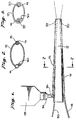
- FIG. 1 there is shown the improved video endoscopic microscope 10 of the present invention. As shown, there is a taper from the proximal to the distal end thereof.
- the endoscope tube 12 is provided with a first tubular channel 14 that extends along one side and which penetrates the side wall so that it is on the interior of the tube 12 at the distal end and recessed somewhat therefrom.
- a second tubular channel 16 extends along the side and penetrates to be on the interior at the distal end, as well.
- a fiber optic bundle 18 carries illuminating light to a lens 20 on the distal end of the second channel 16.
- the fiber optical bundle is coupled to a source of illumination (not shown).
- the first channel 14 is fitted with optical elements and terminates in a scanning lens 22 at the distal end.
- the first channel 14 can then be considered a telescope or possibly a periscope.
- the optical elements include a combination of lenses which give both magnification and an extremely high aperture, approximately f:100.
- a prism 24 which bends the image to an optic coupler 26 which enables attachment of a video camera 28.
- the first and second channels 14, 16 are wholly without the endoscope 12 at the proximal end and are wholly within the endoscope 12 at the distal end.
- FIGS. 2 and 3 are a sectional and end view, respectively, of the endoscope 12.
- first and second channels 14, 16 are shown partially within the endoscope 12 and in FIG. 3, the first and second channels 14, 16 are shown wholly within the endoscope 12.
- a lumen 30 within the endoscope 12 is coupled to a source of oxygen or other gaseous mixture. At its distal end, the lumen 30 directs the gaseous mixture over the lens 22 in the first channel 14 to keep the lens 22 clear of moisture or other visual obstructions.
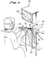
- FIG. 4 there is shown a view of an operating theater in which the endoscope of the present invention is used as a laryngoscope.
- a surgeon 50 has placed a laryngoscope 52 in a patient 54.
- a catheter 56 parallels the laryngoscope 52 and supplies a breathing mixture to the lungs of the patient 54.
- a first, optical channel 58 is coupled to a video camera 60 and a second, illuminating channel 62 is coupled to a source of illumination (not shown).
- a lumen 64 is connected to a tube supplying an appropriate gaseous mixture at a velocity suitable to keep the lens at the distal end of the optical channel from fogging or being otherwise obscured.
- a video monitor 66 is positioned at a height and location convenient to the surgeon 50 and presents an image 68 of the scene at the distal end of the laryngoscope 52 which, in this instance, would be image of the patient's larynx. By watching the monitor 66, the surgeon 50 can manipulate and operate various instruments 70, 72 which are inserted into the proximal end of the laryngoscope 52, the magnified image of which can be viewed.
- the image presented to the surgeon 50 is far superior than was previously available using a surgical microscope. Not only can the entire larynx be visualized on the monitor, because of the high effective aperture, a substantial depth of field is available which means that the image is always in perfect focus.
- the microscopes of the prior art because they were adjacent the surgeon, had to be focussed through the endoscope, the central area of which, therefore, of necessity, had to be kept relatively unobstructed, restricting the kinds and number of instruments available to the surgeon.
- the interior of the endoscope can be filled with instruments so long as the area in the region of the surgical field was visible to the distal lens of the first channel.
- the first channel distal lens had a field of view of approximately 60 and, similarly, the second channel distal end had a lens that directed the illumination to the entire area of interest.
- FIG. 5 there is shown in block diagrammatic form, the various elements that make up a suitable system 110 employing the endoscope of the present invention.
- the endoscope 112 which has a first, optical channel 114 and a second, illuminating channel 116 is shown only in partial view.
- a video camera 128 is connected to the first channel 114 and a fiber bundle 130 couples the second channel 116 to a light source 132.
- the video camera 128 is connected to a video amplifier 134 which drives a monitor 136, a recorder 138 and a printer 140 for a permanent record of successive events of a procedure. Because light amplification as well as signal amplification is possible in the video chain, many utilization devices can be employed with the loss of the image to the surgeon or any degradation of the quality of the image. Such cannot be said of the conventional surgical microscope.
Abstract
Description
- The present invention relates to optical systems and, more particularly, to an improved system for visualizing objects within a surgical endoscopic field in aid of micro-surgical procedures.
- Physicians and especially surgeons have long had the need to see, in detail, the anatomical features upon which they operate during the course of a procedure. In many instances, the operating field is sufficiently exposed and accessible so that the naked eye is adequate for the work at hand. When, however, the objects in the field are too small to be easily seen with the naked eye, or the field is not at the surface, some form of instrumentation is necessary to permit a visualization of the working area.
- For many years, optical instrument makers provided microscopes, both monocular and binocular, which permitted a surgeon to view the surgical field with a selected magnification. Such instruments tend to be large, bulky, and require either a wall or ceiling mounting or a large stand to support the optics without undue vibration. Moreover, such systems required careful alignment and focussing, especially if the depth of field was limited to a plane of approximately one millimeter thickness.
- In many of these optical instruments, beamsplitters could be used to provide a second or more viewing stations. These would be utilized by assistants, students or could be used for archival purposes by mounting cameras or the like. Cameras could be utilized for still or motion picture photography, or, as in more modern systems, video cameras can be employed which are coupled to videotape machines or video monitors.
- In a purely optical system, each time a beamsplitter is employed, the brightness of the transmitted image is reduced, thereby limiting the number of viewing stations by the extent to which the field can be illuminated. It is, of course, possible to use electronic light amplification techniques to the video system, enabling a record to be made under marginal viewing conditions.
- Video cameras have taken a greater role in the surgical theater with the advent of lighter, smaller and higher resolution video cameras. Arthroscopes can be fitted with video cameras so that the surgeon can "see" what he is doing on a large screen, color video monitor. To some extent, the mere transmission of an image from the photosensitive transducer area of the video camera to the much larger screen of the monitor provides some degree of magnification with acceptable image resolution.
- Endoscopes, however, have permitted some visualization of the field with optical paths that have utilized prisms and lenses or optical fibers. Usually such optical paths have either terminated in an eyepiece or in the objective plane of a conventional surgical microscope.
- Conventional surgical microscopes have the several problems associated with large mass and weight, necessitating special supporting stands or mountings. Further, once the patient is readied, the microscope must be trained on the field of interest and focussed. If any photographs are taken, they will appear substantially "flat" and planar since only a fairly "thin" section is in focus at any given time and if a feature or artifact that is closer or farther from the focal plane is to be viewed, the focus of the microscope must be readjusted.
- When the conventional microscope is used with an endoscope, (for example, a laryngoscope for exploring the vocal chords) the object distance is usually around 400 mm so that the microscope does not interfere with the insertion of instruments into the endoscope or with their manipulation. Moreover, the instruments themselves frequently occlude much of the available field of view. Even without an endoscope, dealing with an exposed surgical field still requires careful initial adjustment of the microscope and frequent refocussing if elements of interest are in a plane different from the focal plane.
- If the endoscope is a laryngoscope, the patient must be anaesthetized and the laryngoscope inserted into the mouth and then past the tongue into the trachea. A binocular microscope with an integral light source is positioned approximately 400 mm from the tube and illuminates the field. In most cases, the field of view includes the opening of the laryngoscope into which instruments are inserted, the inner walls of the laryngoscope and the larynx or other organ of interest. Approximately 60% of the field of view is not of interest and is usually out of focus so as to visualize the larynx in focus.
- The surgeon then must introduce whatever instruments he is to use into the laryngoscope in the area between the laryngoscope and the microscope. To a certain extent, the instruments will occlude the field of view and great care must be taken to position the instruments so that they can be seen, in focus, in the microscope eyepieces. Because the depth of field is so shallow, the microscope must be refocussed, each time a different plane is to be viewed. This is a great disadvantage if the object of interest extends for any distance in the axial direction.
- The use of the conventional binocular microscope imposes its own special problems upon the surgeon who must remain more or less immobilized in order to view the field through the binocular eyepieces. Viewing through the small eyepieces also causes fatigue in the viewer, especially if the procedure is a long and difficult one. If an assistant wishes to follow the procedure, an optical beamsplitter can be employed with a second set of eyepieces, but at the cost of available light since each time a beamsplitter is employed, the available light must be divided.
- If one wishes to document the procedure, either through the use of a still camera or a motion picture or video camera, a beamsplitter is required which reduces the illumination to both the primary operator and to the camera. Moreover, the optimum focus for the human viewer may not result in an optimum focus for the camera. To further complicate matters, the shallow depth of field results in much of the foreground and background of the image being out of focus.
- The present invention is intended to alleviate many of the shortcomings of the conventional surgical microscope and to provide many benefits that are presently unavailable. For the purposes of the present invention, the term "endoscope" is intended to include all of the specialized instruments which are introduced into the body of a patient and would include laryngoscopes, mediastinoscopes and rectoscopes, among others.
- Some experimental work has been done with laryngoscopes wherein a special "telescope" was provided that was mounted on the inner wall of the laryngoscope. In one example, a tube of 5.0 mm diameter was fitted with optical elements and fastened to a recess in a side wall. At the distal end, the telescope tube terminated approximately 15 mm from the end of the laryngoscope. The telescope was provided with an objective whose "view" was angled by approximately 6
 with a viewing angle of approximately 60, thereby permitting visualization of the entire area before the laryngoscope.
 - Near the proximal end of the laryngoscope, the telescope tube angled outwardly through the wall of the laryngoscope, terminating in an eyepiece or video camera objective that was positioned off of the axis of the laryngoscope. In a preferred embodiment, the angle is 90, but other orientations are possible, depending upon how one would position the camera.
- Illumination can be provided by a fiber optic bundle that parallels the telescope. Further, a miniature tube (outside diameter of 0.1 mm) can be used to flow oxygen or fresh air to the distal end of the telescope to act as a defogger. The effective aperture of the telescope is quite high, approximately f:100, which provides sufficient depth of field so that a substantial distance beyond the end of the laryngoscope is always in focus and the view to the operator and the camera can be considered three dimensional.
- The key to the present invention is the use of a high resolution, miniaturized color video camera with a sensor area of approximately 6-7 mm diameter. An optical system brings the image of an area whose diameter is approximately 20 mm to the sensor element. The use of an all electronic system enables the use of a large screen, high resolution monitor to present the working area to the surgeon as well as to assistants and aides. Because the system is electronic, additional monitors can be placed in different locations for use by others in the surgical team or by students and spectators.
- The electronic video signal can also drive video recorders, still cameras and/or printers which are capable of giving a "hard copy" record of any particular scene that is shown on the monitor for an archival record of the procedure without the need for additional illumination. Electronic image enhancers or light amplifiers can provide excellent images with the available light from the fiber optic illuminating system.
- Further advantages and features of the present invention will be more fully apparent to those skilled in the art to which the invention pertains from the ensuing detailed description thereof, regarded in conjunction with the accompanying drawings wherein like reference numerals refer to like parts throughout and in which:
- FIG. 1 is a bottom view of an improved video microscopic endoscope according to the present invention;
- FIG. 2 is a section view of the endoscope of FIG. 1, taken along line 2-2 in the direction of the appended arrows;
- FIG. 3 is an end view of the distal end of the endoscope of FIG. 1:
- FIG. 4 is a side section view of the endoscope of the present invention employed as a laryngoscope, showing also the associated video camera and display equipment; and
- FIG. 5 is a block diagram illustrating one possible video setup including monitors and recording devices.
- Turning first to FIG. 1, there is shown the improved video endoscopic microscope 10 of the present invention. As shown, there is a taper from the proximal to the distal end thereof. The
endoscope tube 12 is provided with a firsttubular channel 14 that extends along one side and which penetrates the side wall so that it is on the interior of thetube 12 at the distal end and recessed somewhat therefrom. - Similarly, on the opposite wall, a second
tubular channel 16 extends along the side and penetrates to be on the interior at the distal end, as well. A fiberoptic bundle 18 carries illuminating light to alens 20 on the distal end of thesecond channel 16. The fiber optical bundle is coupled to a source of illumination (not shown). - The
first channel 14 is fitted with optical elements and terminates in ascanning lens 22 at the distal end. Thefirst channel 14 can then be considered a telescope or possibly a periscope. The optical elements include a combination of lenses which give both magnification and an extremely high aperture, approximately f:100. At the proximal end of thefirst channel 14 ia aprism 24 which bends the image to anoptic coupler 26 which enables attachment of avideo camera 28. - As seen in FIG. 1, the first and
second channels endoscope 12 at the proximal end and are wholly within theendoscope 12 at the distal end. This can also be seen in connection with FIGS. 2 and 3, which are a sectional and end view, respectively, of theendoscope 12. - In FIG. 2, the first and
second channels endoscope 12 and in FIG. 3, the first andsecond channels endoscope 12. Alumen 30 within theendoscope 12 is coupled to a source of oxygen or other gaseous mixture. At its distal end, thelumen 30 directs the gaseous mixture over thelens 22 in thefirst channel 14 to keep thelens 22 clear of moisture or other visual obstructions. - Turning next to FIG. 4, there is shown a view of an operating theater in which the endoscope of the present invention is used as a laryngoscope. A
surgeon 50 has placed alaryngoscope 52 in apatient 54. Acatheter 56 parallels thelaryngoscope 52 and supplies a breathing mixture to the lungs of thepatient 54. A first,optical channel 58 is coupled to avideo camera 60 and a second, illuminatingchannel 62 is coupled to a source of illumination (not shown). A lumen 64 is connected to a tube supplying an appropriate gaseous mixture at a velocity suitable to keep the lens at the distal end of the optical channel from fogging or being otherwise obscured. - A
video monitor 66 is positioned at a height and location convenient to thesurgeon 50 and presents animage 68 of the scene at the distal end of thelaryngoscope 52 which, in this instance, would be image of the patient's larynx. By watching themonitor 66, thesurgeon 50 can manipulate and operatevarious instruments 70, 72 which are inserted into the proximal end of thelaryngoscope 52, the magnified image of which can be viewed. - Because of the magnification available through the optical system of the
first channel 58, and the relative sizes of the monitor screen and the video transducer surface, the image presented to thesurgeon 50 is far superior than was previously available using a surgical microscope. Not only can the entire larynx be visualized on the monitor, because of the high effective aperture, a substantial depth of field is available which means that the image is always in perfect focus. - Further, the microscopes of the prior art, because they were adjacent the surgeon, had to be focussed through the endoscope, the central area of which, therefore, of necessity, had to be kept relatively unobstructed, restricting the kinds and number of instruments available to the surgeon. In the present invention, the interior of the endoscope can be filled with instruments so long as the area in the region of the surgical field was visible to the distal lens of the first channel.
- In preferred embodiments of the present invention, the first channel distal lens had a field of view of approximately 60and, similarly, the second channel distal end had a lens that directed the illumination to the entire area of interest.
- Finally, in FIG. 5, there is shown in block diagrammatic form, the various elements that make up a
suitable system 110 employing the endoscope of the present invention. Theendoscope 112, which has a first,optical channel 114 and a second, illuminatingchannel 116 is shown only in partial view. Avideo camera 128 is connected to thefirst channel 114 and afiber bundle 130 couples thesecond channel 116 to alight source 132. - The
video camera 128 is connected to avideo amplifier 134 which drives amonitor 136, arecorder 138 and aprinter 140 for a permanent record of successive events of a procedure. Because light amplification as well as signal amplification is possible in the video chain, many utilization devices can be employed with the loss of the image to the surgeon or any degradation of the quality of the image. Such cannot be said of the conventional surgical microscope.
Claims (10)
- An endoscope having a proximal end and a distal end for visualizing the surgical field to assist in microsurgical procedures comprising in combination;a) a light source within the endoscope for illuminating the field adjacent the distal end of the endoscope;b) a high resolution video camera having a sensitive image receiving area of from 7-10 mm in diameter;c) a high resolution video monitor coupled to said camera for displaying images impinging upon said image receiving area; andd) lens system means including a first tube integral with the endoscope, said lens system means having a field of view of an area ranging from 15 to 25 mm with a depth of field ranging from 10 to 20 mm;whereby magnified images of objects of interest adjacent the distal end of the endoscope can be displayed on said video monitor to aid in microsurgical procedures.
- The endoscope of claim 1, above, wherein the endoscope includes a lumen having a distal end adjacent the distal end of said lens system means for ventilating and clearing the distal end of said lens system means.
- The endoscope of claim 1, above, wherein the area of the displayed image at said sensitive image receiving area is approximately 7 mm.
- The endoscope of claim 1, above, wherein said light source includes a fiber optic bundle within a second tube integral with the endoscope and having a distal end at the distal end of the endoscope for illuminating the area visualized by said lens system means.
- The endoscope of claim 1, above, wherein said lens system means includes viewing means extending laterally from the endoscope and coupled to said video camera for applying a magnified image to said image receiving area.
- The endoscope of claim 5, above, wherein said viewing means diverts images laterally through the wall of the endoscope near the proximal end thereof to provide a camera viewing port remote from the central opening of the endoscope.
- The endoscope of claim 1, above, wherein said lens system means includes an objective lens at said first tube distal end adjacent the distal end of the endoscope.
- The endoscope of claim 7, above, wherein said objective lens is recessed approximately 15 mm from the distal end of the endoscope.
- The endoscope of claim 7, above, wherein said objective lens is offset by 5'.
- The endoscope of claim 7, above, wherein said objective lens has a field of view of approximately 60.
Priority Applications (6)
| Application Number | Priority Date | Filing Date | Title |
|---|---|---|---|
| US07/226,417 US4877016A (en) | 1988-07-29 | 1988-07-29 | Video endoscopic microscope |
| CA000609552A CA1318968C (en) | 1988-07-29 | 1989-08-28 | Video endoscopic microscope |
| PCT/US1989/003899 WO1991004703A1 (en) | 1988-07-29 | 1989-09-28 | Video endoscopic microscope |
| DE68927186T DE68927186T2 (en) | 1988-07-29 | 1989-09-28 | VIDEO ENDOSCOPE |
| EP95118946A EP0712601A1 (en) | 1988-07-29 | 1989-09-28 | Video endoscope |
| EP89912537A EP0494134B1 (en) | 1988-07-29 | 1989-09-28 | Video endoscope |
Applications Claiming Priority (3)
| Application Number | Priority Date | Filing Date | Title |
|---|---|---|---|
| US07/226,417 US4877016A (en) | 1988-07-29 | 1988-07-29 | Video endoscopic microscope |
| EP95118946A EP0712601A1 (en) | 1988-07-29 | 1989-09-28 | Video endoscope |
| EP89912537A EP0494134B1 (en) | 1988-07-29 | 1989-09-28 | Video endoscope |
Related Parent Applications (1)
| Application Number | Title | Priority Date | Filing Date |
|---|---|---|---|
| EP89912537.1 Division | 1989-09-28 |
Publications (1)
| Publication Number | Publication Date |
|---|---|
| EP0712601A1 true EP0712601A1 (en) | 1996-05-22 |
Family
ID=26138953
Family Applications (2)
| Application Number | Title | Priority Date | Filing Date |
|---|---|---|---|
| EP89912537A Expired - Lifetime EP0494134B1 (en) | 1988-07-29 | 1989-09-28 | Video endoscope |
| EP95118946A Withdrawn EP0712601A1 (en) | 1988-07-29 | 1989-09-28 | Video endoscope |
Family Applications Before (1)
| Application Number | Title | Priority Date | Filing Date |
|---|---|---|---|
| EP89912537A Expired - Lifetime EP0494134B1 (en) | 1988-07-29 | 1989-09-28 | Video endoscope |
Country Status (5)
| Country | Link |
|---|---|
| US (1) | US4877016A (en) |
| EP (2) | EP0494134B1 (en) |
| CA (1) | CA1318968C (en) |
| DE (1) | DE68927186T2 (en) |
| WO (1) | WO1991004703A1 (en) |
Cited By (3)
| Publication number | Priority date | Publication date | Assignee | Title |
|---|---|---|---|---|
| WO2004030527A1 (en) * | 2002-10-03 | 2004-04-15 | Etview Ltd. | Tube for inspecting internal organs of a body |
| US10149602B2 (en) | 2011-07-11 | 2018-12-11 | Ambu A/S | Endobronchial tube with integrated image sensor and a cleaning nozzle arrangement |
| US10245402B2 (en) | 2011-07-11 | 2019-04-02 | Ambu A/S | Endobronchial tube with integrated image sensor |
Families Citing this family (84)
| Publication number | Priority date | Publication date | Assignee | Title |
|---|---|---|---|---|
| US4877016A (en) * | 1988-07-29 | 1989-10-31 | Kantor Edward A | Video endoscopic microscope |
| JPH04357927A (en) * | 1991-01-14 | 1992-12-10 | Olympus Optical Co Ltd | Endoscope image display device |
| US5370134A (en) * | 1991-05-29 | 1994-12-06 | Orgin Medsystems, Inc. | Method and apparatus for body structure manipulation and dissection |
| AU3721993A (en) * | 1992-02-19 | 1993-09-13 | United States Surgical Corporation | Optical viewing device |
| US5416634A (en) * | 1992-09-11 | 1995-05-16 | United States Surgical Corporation | Optical viewing device |
| US5373840A (en) * | 1992-10-02 | 1994-12-20 | Knighton; David R. | Endoscope and method for vein removal |
| WO1994009694A1 (en) * | 1992-10-28 | 1994-05-11 | Arsenault, Dennis, J. | Electronic endoscope |
| US5369525A (en) * | 1992-12-02 | 1994-11-29 | United States Surgical Corporation | Ring lens assembly for an optical viewing device |
| US5400771A (en) * | 1993-01-21 | 1995-03-28 | Pirak; Leon | Endotracheal intubation assembly and related method |
| US6010531A (en) | 1993-02-22 | 2000-01-04 | Heartport, Inc. | Less-invasive devices and methods for cardiac valve surgery |
| US5682906A (en) * | 1993-02-22 | 1997-11-04 | Heartport, Inc. | Methods of performing intracardiac procedures on an arrested heart |
| US5588949A (en) * | 1993-10-08 | 1996-12-31 | Heartport, Inc. | Stereoscopic percutaneous visualization system |
| US5957832A (en) * | 1993-10-08 | 1999-09-28 | Heartport, Inc. | Stereoscopic percutaneous visualization system |
| US5518146A (en) * | 1994-10-03 | 1996-05-21 | Mattei; Glenn M. | Method of handling defogging agents used in operating rooms |
| JP3642812B2 (en) * | 1994-11-17 | 2005-04-27 | 株式会社町田製作所 | Medical observation device |
| US5707389A (en) * | 1995-06-07 | 1998-01-13 | Baxter International Inc. | Side branch occlusion catheter device having integrated endoscope for performing endoscopically visualized occlusion of the side branches of an anatomical passageway |
| US7384423B1 (en) | 1995-07-13 | 2008-06-10 | Origin Medsystems, Inc. | Tissue dissection method |
| US5772576A (en) | 1995-12-11 | 1998-06-30 | Embro Vascular L.L.C. | Apparatus and method for vein removal |
| US5891013A (en) * | 1996-02-07 | 1999-04-06 | Pinotage, Llc | System for single-puncture endoscopic surgery |
| US5800344A (en) * | 1996-10-23 | 1998-09-01 | Welch Allyn, Inc. | Video laryngoscope |
| US5944654A (en) * | 1996-11-14 | 1999-08-31 | Vista Medical Technologies, Inc. | Endoscope with replaceable irrigation tube |
| DE19734591C1 (en) * | 1997-08-09 | 1999-06-17 | Ruesch Willy Ag | Laryngoscope |
| US5929044A (en) * | 1997-08-14 | 1999-07-27 | Cornell Research Foundation | Protein solder composition and method of use |
| US6543447B2 (en) † | 1997-12-01 | 2003-04-08 | Saturn Biomedical Systems Inc | Intubation instrument |
| US6976957B1 (en) | 1998-06-22 | 2005-12-20 | Origin Medsystems, Inc. | Cannula-based surgical instrument and method |
| US6830546B1 (en) | 1998-06-22 | 2004-12-14 | Origin Medsystems, Inc. | Device and method for remote vessel ligation |
| US7326178B1 (en) | 1998-06-22 | 2008-02-05 | Origin Medsystems, Inc. | Vessel retraction device and method |
| EP0979635A2 (en) | 1998-08-12 | 2000-02-16 | Origin Medsystems, Inc. | Tissue dissector apparatus |
| US20030081310A1 (en) * | 1998-09-09 | 2003-05-01 | Mcmanus Dennis Q. | Microscopy method and apparatus |
| AU5215399A (en) | 1998-09-09 | 2000-03-27 | Dennis Q. Mcmanus | Microscopy method and apparatus |
| WO2000071018A1 (en) | 1999-05-21 | 2000-11-30 | Karl Storz Gmbh & Co. Kg | Laryngoscope |
| US6719752B2 (en) * | 2000-08-31 | 2004-04-13 | Pentax Corporation | Endoscopic treatment instrument |
| US6558313B1 (en) | 2000-11-17 | 2003-05-06 | Embro Corporation | Vein harvesting system and method |
| IL143682A0 (en) * | 2001-06-11 | 2002-04-21 | Shalman Michael | Endoscope with cleaning optics |
| US20030163030A1 (en) * | 2002-02-25 | 2003-08-28 | Arriaga Moises A. | Hollow endoscopy |
| US6840903B2 (en) | 2002-03-21 | 2005-01-11 | Nuvista Technology Corporation | Laryngoscope with image sensor |
| US9820641B2 (en) | 2003-04-29 | 2017-11-21 | Aircraft Medical Limited | Laryngoscope with camera attachment |
| WO2005018466A2 (en) * | 2003-08-26 | 2005-03-03 | Endius, Inc. | Access systems and methods for minimally invasive surgery |
| DE10349649B3 (en) | 2003-10-17 | 2005-05-19 | Karl Storz Gmbh & Co. Kg | A method and apparatus for generating an annotated image in a sterile work area of a medical facility |
| US20050251192A1 (en) * | 2004-03-31 | 2005-11-10 | Shluzas Alan E | Access device having discrete visualization locations |
| WO2006007410A2 (en) | 2004-06-16 | 2006-01-19 | Medtronic, Inc. | Minimally invasive coring vein harvester |
| US20070179342A1 (en) * | 2006-01-12 | 2007-08-02 | Kb Port Llc | Wireless Laryngoscope with Internal Antennae and One Piece Construction Adapted for Laryngoscopy Training |
| US8915842B2 (en) * | 2008-07-14 | 2014-12-23 | Ethicon Endo-Surgery, Inc. | Methods and devices for maintaining visibility and providing irrigation and/or suction during surgical procedures |
| US8579807B2 (en) | 2008-04-28 | 2013-11-12 | Ethicon Endo-Surgery, Inc. | Absorbing fluids in a surgical access device |
| US8690831B2 (en) | 2008-04-25 | 2014-04-08 | Ethicon Endo-Surgery, Inc. | Gas jet fluid removal in a trocar |
| US9770230B2 (en) | 2006-06-01 | 2017-09-26 | Maquet Cardiovascular Llc | Endoscopic vessel harvesting system components |
| US20080081948A1 (en) * | 2006-10-03 | 2008-04-03 | Ethicon Endo-Surgery, Inc. | Apparatus for cleaning a distal scope end of a medical viewing scope |
| US8425602B2 (en) * | 2007-02-09 | 2013-04-23 | Alphatec Spine, Inc. | Curvilinear spinal access method and device |
| US20080287937A1 (en) * | 2007-05-15 | 2008-11-20 | Warsaw Orthopedic, Inc. | Surgical Instrument for Illuminating and Monitoring a Surgical Site |
| US8982203B2 (en) * | 2007-06-06 | 2015-03-17 | Karl Storz Gmbh & Co. Kg | Video system for viewing an object on a body |
| US9050036B2 (en) * | 2007-06-19 | 2015-06-09 | Minimally Invasive Devices, Inc. | Device for maintaining visualization with surgical scopes |
| US9211059B2 (en) | 2007-06-19 | 2015-12-15 | Minimally Invasive Devices, Inc. | Systems and methods for optimizing and maintaining visualization of a surgical field during the use of surgical scopes |
| US8100929B2 (en) | 2007-06-29 | 2012-01-24 | Ethicon Endo-Surgery, Inc. | Duckbill seal with fluid drainage feature |
| US7976501B2 (en) | 2007-12-07 | 2011-07-12 | Ethicon Endo-Surgery, Inc. | Trocar seal with reduced contact area |
| US20090234193A1 (en) * | 2008-03-13 | 2009-09-17 | Ethicon Endo-Surgery, Inc. | Apparatus for keeping clean a distal scope end of a medical viewing scope |
| US11235111B2 (en) | 2008-04-28 | 2022-02-01 | Ethicon Llc | Surgical access device |
| USD700326S1 (en) | 2008-04-28 | 2014-02-25 | Ethicon Endo-Surgery, Inc. | Trocar housing |
| US9358041B2 (en) | 2008-04-28 | 2016-06-07 | Ethicon Endo-Surgery, Llc | Wicking fluid management in a surgical access device |
| US8568362B2 (en) | 2008-04-28 | 2013-10-29 | Ethicon Endo-Surgery, Inc. | Surgical access device with sorbents |
| US8870747B2 (en) | 2008-04-28 | 2014-10-28 | Ethicon Endo-Surgery, Inc. | Scraping fluid removal in a surgical access device |
| US8636686B2 (en) | 2008-04-28 | 2014-01-28 | Ethicon Endo-Surgery, Inc. | Surgical access device |
| US8273060B2 (en) | 2008-04-28 | 2012-09-25 | Ethicon Endo-Surgery, Inc. | Fluid removal in a surgical access device |
| US7981092B2 (en) | 2008-05-08 | 2011-07-19 | Ethicon Endo-Surgery, Inc. | Vibratory trocar |
| US8764638B2 (en) | 2008-10-17 | 2014-07-01 | Al Medical Devices, Inc. | Endotracheal intubation device |
| USD613403S1 (en) | 2008-12-10 | 2010-04-06 | Minimally Invasive Devices, Llc | Sheath tip for maintaining surgical scope visualization |
| CA2746371C (en) | 2008-12-10 | 2015-08-04 | Minimally Invasive Devices, Inc. | Systems and methods for optimizing and maintaining visualization of a surgical field during the use of surgical scopes |
| DK2393538T3 (en) | 2009-02-06 | 2017-11-27 | Endoclear Llc | Devices for cleaning endotracheal tubes |
| US8468637B2 (en) | 2009-02-06 | 2013-06-25 | Endoclear Llc | Mechanically-actuated endotracheal tube cleaning device |
| US9078562B2 (en) | 2010-01-11 | 2015-07-14 | Minimally Invasive Devices, Inc. | Systems and methods for optimizing and maintaining visualization of a surgical field during the use of surgical scopes |
| EP2902066B1 (en) | 2010-03-29 | 2021-03-10 | Endoclear LLC | Airway cleaning and visualization |
| US8414481B2 (en) | 2010-06-24 | 2013-04-09 | General Electric Company | Laryngoscope |
| US9888832B2 (en) | 2010-09-24 | 2018-02-13 | Blink Device LLC | Endotracheal intubation device |
| WO2012075487A2 (en) | 2010-12-03 | 2012-06-07 | Minimally Invasive Devices, Llc | Devices, systems, and methods for performing endoscopic surgical procedures |
| WO2013063520A1 (en) | 2011-10-27 | 2013-05-02 | Endoclear, Llc | Endotracheal tube coupling adapters |
| US9622651B2 (en) | 2012-01-27 | 2017-04-18 | Kbport Llc | Wireless laryngoscope simulator with onboard event recording adapted for laryngoscopy training |
| EP2928517B1 (en) | 2012-12-04 | 2021-02-17 | Endoclear LLC | Suction cleaning devices |
| WO2014151824A1 (en) | 2013-03-14 | 2014-09-25 | Minimally Invasive Devices, Inc. | Fluid dispensing control systems and methods |
| CN106028930B (en) | 2014-02-21 | 2021-10-22 | 3D集成公司 | Kit comprising a surgical instrument |
| EP3151898B1 (en) | 2014-06-03 | 2021-03-24 | Endoclear LLC | Cleaning devices, systems and methods |
| US11020144B2 (en) | 2015-07-21 | 2021-06-01 | 3Dintegrated Aps | Minimally invasive surgery system |
| WO2017012624A1 (en) | 2015-07-21 | 2017-01-26 | 3Dintegrated Aps | Cannula assembly kit, trocar assembly kit, sleeve assembly, minimally invasive surgery system and method therefor |
| DE102015216572A1 (en) * | 2015-08-31 | 2016-05-12 | Carl Zeiss Meditec Ag | Device for deflecting an optical beam path and medical visualization device with such a device |
| DK178899B1 (en) | 2015-10-09 | 2017-05-08 | 3Dintegrated Aps | A depiction system |
| JP7110174B2 (en) * | 2016-08-17 | 2022-08-01 | リバウンド セラピュティクス コーポレーション | Cannula with proximally mounted camera |
Citations (5)
| Publication number | Priority date | Publication date | Assignee | Title |
|---|---|---|---|---|
| EP0022220A2 (en) * | 1979-07-05 | 1981-01-14 | Olympus Optical Co., Ltd. | Multiple viewing attachment for an endoscope |
| DE3045162A1 (en) * | 1980-12-01 | 1982-07-01 | Heitlinger, Paul, Dr., 6054 Rodgau | Probe for dental examination - has optic fibre cable and video camera |
| US4756304A (en) * | 1986-10-08 | 1988-07-12 | Watanabe Robert S | Arthroscopic video camera system |
| EP0316244A1 (en) * | 1987-11-12 | 1989-05-17 | Welch Allyn, Inc. | Video equipped endoscope with needle probe |
| US4877016A (en) * | 1988-07-29 | 1989-10-31 | Kantor Edward A | Video endoscopic microscope |
Family Cites Families (12)
| Publication number | Priority date | Publication date | Assignee | Title |
|---|---|---|---|---|
| US31289A (en) * | 1861-02-05 | Adjusting coupling-link of railway-cars | ||
| US2243285A (en) * | 1936-01-06 | 1941-05-27 | Charles E Pope | Operating scope |
| US2932294A (en) * | 1954-10-13 | 1960-04-12 | Centre Nat Rech Scient | Lighting devices for endoscopes |
| US2987960A (en) * | 1958-02-17 | 1961-06-13 | Bausch & Lomb | Optical system for endoscopes and the like |
| US3373736A (en) * | 1965-03-22 | 1968-03-19 | Smith Kline French Lab | Sigmoidoscope and illuminating means therefor |
| US3496931A (en) * | 1966-09-20 | 1970-02-24 | Pilling Co | Illuminating endoscope with oval fiber optic channel |
| US3592199A (en) * | 1970-02-09 | 1971-07-13 | Medical Products Corp | Autoclavable surgical instrument illumination |
| DE2932116C2 (en) * | 1979-08-08 | 1981-10-01 | Richard Wolf Gmbh, 7134 Knittlingen | Endoscope for displaying infrared images |
| US4413278A (en) * | 1981-10-05 | 1983-11-01 | Designs For Vision, Inc. | Optical coupling apparatus for coupling an arthoscope to a camera |
| US4567882A (en) * | 1982-12-06 | 1986-02-04 | Vanderbilt University | Method for locating the illuminated tip of an endotracheal tube |
| US4714075A (en) * | 1986-02-10 | 1987-12-22 | Welch Allyn, Inc. | Biopsy channel for endoscope |
| US4846153A (en) * | 1988-06-10 | 1989-07-11 | George Berci | Intubating video endoscope |
-
1988
- 1988-07-29 US US07/226,417 patent/US4877016A/en not_active Expired - Lifetime
-
1989
- 1989-08-28 CA CA000609552A patent/CA1318968C/en not_active Expired - Lifetime
- 1989-09-28 DE DE68927186T patent/DE68927186T2/en not_active Expired - Lifetime
- 1989-09-28 EP EP89912537A patent/EP0494134B1/en not_active Expired - Lifetime
- 1989-09-28 EP EP95118946A patent/EP0712601A1/en not_active Withdrawn
- 1989-09-28 WO PCT/US1989/003899 patent/WO1991004703A1/en active IP Right Grant
Patent Citations (5)
| Publication number | Priority date | Publication date | Assignee | Title |
|---|---|---|---|---|
| EP0022220A2 (en) * | 1979-07-05 | 1981-01-14 | Olympus Optical Co., Ltd. | Multiple viewing attachment for an endoscope |
| DE3045162A1 (en) * | 1980-12-01 | 1982-07-01 | Heitlinger, Paul, Dr., 6054 Rodgau | Probe for dental examination - has optic fibre cable and video camera |
| US4756304A (en) * | 1986-10-08 | 1988-07-12 | Watanabe Robert S | Arthroscopic video camera system |
| EP0316244A1 (en) * | 1987-11-12 | 1989-05-17 | Welch Allyn, Inc. | Video equipped endoscope with needle probe |
| US4877016A (en) * | 1988-07-29 | 1989-10-31 | Kantor Edward A | Video endoscopic microscope |
Cited By (5)
| Publication number | Priority date | Publication date | Assignee | Title |
|---|---|---|---|---|
| WO2004030527A1 (en) * | 2002-10-03 | 2004-04-15 | Etview Ltd. | Tube for inspecting internal organs of a body |
| US10149602B2 (en) | 2011-07-11 | 2018-12-11 | Ambu A/S | Endobronchial tube with integrated image sensor and a cleaning nozzle arrangement |
| US10245402B2 (en) | 2011-07-11 | 2019-04-02 | Ambu A/S | Endobronchial tube with integrated image sensor |
| US10406309B2 (en) | 2011-07-11 | 2019-09-10 | Ambu A/S | Endobronchial tube with integrated image sensor and a cleaning nozzle arrangement |
| US10888679B2 (en) | 2011-07-11 | 2021-01-12 | Ambu A/S | Endobronchial tube with integrated image sensor |
Also Published As
| Publication number | Publication date |
|---|---|
| EP0494134B1 (en) | 1996-09-11 |
| EP0494134A4 (en) | 1992-05-18 |
| WO1991004703A1 (en) | 1991-04-18 |
| DE68927186D1 (en) | 1996-10-17 |
| CA1318968C (en) | 1993-06-08 |
| DE68927186T2 (en) | 1997-02-06 |
| US4877016A (en) | 1989-10-31 |
| EP0494134A1 (en) | 1992-07-15 |
Similar Documents
| Publication | Publication Date | Title |
|---|---|---|
| US4877016A (en) | Video endoscopic microscope | |
| US4651201A (en) | Stereoscopic endoscope arrangement | |
| EP0951861B1 (en) | Medical observing instrument | |
| US9468360B2 (en) | Video system for viewing an object on a body | |
| US5363839A (en) | Video otoscope | |
| EP1062905B1 (en) | Intubating laryngoscope providing for ready interchange of blades and corresponding intubating laryngoscope system | |
| US5239984A (en) | Hand-held opto-diagnostic instrument system | |
| US7914444B2 (en) | Endoscope system and endoscope | |
| US5846185A (en) | High resolution, wide field of view endoscopic viewing system | |
| EP1508294A1 (en) | Endoscope hood | |
| US4987488A (en) | Video system for visualizing microsurgical images with enhanced depth of field | |
| JPH11123175A (en) | Laryngoscope | |
| JPS60203230A (en) | Endoscope using solid image pick-up element | |
| WO1992015238A1 (en) | An improved micro-endoscope | |
| JPH11155798A (en) | Hard endoscope | |
| JPH05341210A (en) | Stereoscopic endoscope device | |
| JP3714636B2 (en) | Endoscope device | |
| JP4493141B2 (en) | Endoscope | |
| JPS5846925A (en) | Endoscope apparatus using solid photographing element | |
| JPH08122665A (en) | Stereovision endoscope | |
| JPH04507305A (en) | endoscope with television camera | |
| JPS6311929Y2 (en) | ||
| JPS5990542A (en) | Observation image treatng system of endoscope | |
| Allhoff et al. | The chip camera: perfect imaging in endourology | |
| JPH0510648B2 (en) |
Legal Events
| Date | Code | Title | Description |
|---|---|---|---|
| PUAI | Public reference made under article 153(3) epc to a published international application that has entered the european phase |
Free format text: ORIGINAL CODE: 0009012 |
|
| 17P | Request for examination filed |
Effective date: 19951212 |
|
| AC | Divisional application: reference to earlier application |
Ref document number: 494134 Country of ref document: EP |
|
| AK | Designated contracting states |
Kind code of ref document: A1 Designated state(s): CH DE FR GB LI |
|
| RIN1 | Information on inventor provided before grant (corrected) |
Inventor name: EDWARD A. KANTOR Inventor name: BERCI, GEORGE Inventor name: STORZ, KARL |
|
| RAP1 | Party data changed (applicant data changed or rights of an application transferred) |
Owner name: KARL STORZ GMBH & CO. KG |
|
| 17Q | First examination report despatched |
Effective date: 20000210 |
|
| STAA | Information on the status of an ep patent application or granted ep patent |
Free format text: STATUS: THE APPLICATION IS DEEMED TO BE WITHDRAWN |
|
| 18D | Application deemed to be withdrawn |
Effective date: 20010613 |