EP0713262A2 - Antenna apparatus and direction method - Google Patents
Antenna apparatus and direction method Download PDFInfo
- Publication number
- EP0713262A2 EP0713262A2 EP95308223A EP95308223A EP0713262A2 EP 0713262 A2 EP0713262 A2 EP 0713262A2 EP 95308223 A EP95308223 A EP 95308223A EP 95308223 A EP95308223 A EP 95308223A EP 0713262 A2 EP0713262 A2 EP 0713262A2
- Authority
- EP
- European Patent Office
- Prior art keywords
- antenna
- signal
- signal strength
- antenna patterns
- message
- Prior art date
- Legal status (The legal status is an assumption and is not a legal conclusion. Google has not performed a legal analysis and makes no representation as to the accuracy of the status listed.)
- Granted
Links
Images


Classifications
-
- H—ELECTRICITY
- H01—ELECTRIC ELEMENTS
- H01Q—ANTENNAS, i.e. RADIO AERIALS
- H01Q1/00—Details of, or arrangements associated with, antennas
- H01Q1/12—Supports; Mounting means
- H01Q1/22—Supports; Mounting means by structural association with other equipment or articles
- H01Q1/24—Supports; Mounting means by structural association with other equipment or articles with receiving set
-
- H—ELECTRICITY
- H01—ELECTRIC ELEMENTS
- H01Q—ANTENNAS, i.e. RADIO AERIALS
- H01Q1/00—Details of, or arrangements associated with, antennas
- H01Q1/12—Supports; Mounting means
- H01Q1/22—Supports; Mounting means by structural association with other equipment or articles
- H01Q1/2258—Supports; Mounting means by structural association with other equipment or articles used with computer equipment
-
- H—ELECTRICITY
- H01—ELECTRIC ELEMENTS
- H01Q—ANTENNAS, i.e. RADIO AERIALS
- H01Q3/00—Arrangements for changing or varying the orientation or the shape of the directional pattern of the waves radiated from an antenna or antenna system
- H01Q3/24—Arrangements for changing or varying the orientation or the shape of the directional pattern of the waves radiated from an antenna or antenna system varying the orientation by switching energy from one active radiating element to another, e.g. for beam switching
-
- H—ELECTRICITY
- H01—ELECTRIC ELEMENTS
- H01Q—ANTENNAS, i.e. RADIO AERIALS
- H01Q3/00—Arrangements for changing or varying the orientation or the shape of the directional pattern of the waves radiated from an antenna or antenna system
- H01Q3/26—Arrangements for changing or varying the orientation or the shape of the directional pattern of the waves radiated from an antenna or antenna system varying the relative phase or relative amplitude of energisation between two or more active radiating elements; varying the distribution of energy across a radiating aperture
- H01Q3/2605—Array of radiating elements provided with a feedback control over the element weights, e.g. adaptive arrays
Definitions
- the present invention relates to antenna apparatus and in particular, to a method and apparatus employing adaptive antenna pattern technology to provide improved signal directionality to reduce the power required for communication by a mobile or remote transceiver.
- U.S. Patent No. 5,260,968 to Gardner et al. discloses a method for "multiplexing radio communication signals," and uses “blind adaptive spatial filtering of spectrally overlapping signals.” This method employs “self [spectral] coherence restoral” techniques which require complicated digital signal processing apparatus to provide the autocorrelation functions necessary to implement the method. Gardener's "adaptive" antenna array is situated at the base station, rather than at the mobile site.
- the present invention seeks to provide for an antenna apparatus and method having advantages over known apparatus and methods.
- antenna apparatus comprising antenna means connected to a transceiver means for receiving a first signal from a remote station and for transmitting a second signal to said remote station, and characterised in that said antenna means is adaptable to generate at least one of a plurality of antenna patterns having different directionality, and in that switch means operable with said antenna means is provided for selecting one of said antenna patterns which provides maximum signal strength of said first signal received from said remote station.
- Preferably said different antenna patterns have mutually exclusive directions.
- a method for directionally adapting antenna apparatus characterised by the steps of receiving, via an antenna having at least two monopole elements a first signal from said remote station and transmitting a second signal to said remote station, determining an optimum antenna patterns which provides a maximum signal amplitude of said first signal received from said remote station and establishing a desired signal phase relationship between each of said monopole elements to generate said optimum antenna pattern.
- the method of the present invention can advantageously teach away from the known methods such as Roberts by seeking signal maximums in a received signal.
- the invention can prove particularly advantageous in employing an adaptive directional multiple-monopole antenna system.
- a system can advantageously be provided which reduces the power consumption of a cellular phone or other similar remote transceiver.
- an adaptive directional antenna is used to radiate RF power in the direction of the cellular phone (or other) base station instead of radiating the RF power omnidirectionally.
- the directionality of the antenna is useful for reception as well as transmission, because it increases the strength of the received signal and reduces the amount of noise picked up by the cellular transceiver.
- the present system is particularly well suited to portable computing applications, such as those using a laptop computer or other remote computing device such as a "personal digital assistant".
- One exemplary embodiment of the present system includes a simple adaptive antenna system which can be switched, either manually or via microprocessor, to direct the radiated RF energy into, for example, quadrants or hemispheres in the vicinity of a communicating base station or satellite.
- This system saves transceiver battery power and compensates for large changes in orientation of the mobile transceiver with respect to the base station/satellite while maximizing signal gain between the transceiver and the base station/satellite.
- a "handoff protocol" is used to transfer the communication link from one base station to another when the cellular phone (or other transceiver) signal passes from one cell to another cell in the cellular network.
- this same technique may be used to transfer the communication link from one orbiting satellite to another.
- An alternative embodiment of the present system changes the direction of the transceiver antenna direction to direct the antenna pattern toward the new base station/satellite when a handoff is made.
- the transfer of communications from one cell to another is accomplished via the handoff protocol itself, wherein the cellular phone adapts the antenna configuration whenever a handoff is detected via the communication received from the base station.
- Another alternative embodiment of the present system periodically scans for the direction of the strongest return signal.
- the cellular phone automatically adapts the antenna pattern at the next periodic direction scan.
- FIG. 1 For instance, two monopoles mounted on the ends of a notebook computer. Furthermore, since wide antenna pattern lobes are desirable, a simple two-monopole adaptive antenna is well suited to the present system.
- a number of portable cellular devices are presently commercially available. Since all of these portable devices are typically battery powered, the operating period of each device is limited by the battery "life" available between successive recharges. Because the life of a given battery is extended by reducing the power consumption of the device connected to the battery, it follows that reducing the power consumption of a battery powered cellular phone device is highly desirable.
- a remote/mobile cellular transceiver to receive and transmit signals between a base station or satellite and the transceiver so as to establish an energy efficient communication path from the transceiver to the base station.
- the invention described herein is applicable to either base stations or satellites. The remaining description will describe the use of "base stations", however these techniques are similarly applicable to satellites as well.
- the present system is particularly advantageous in that the reduction of transceiver power consumption requires only minimal hardware enhancements to existing cellular transceiver systems.
- a further advantage of the present invention is that the system enhances the signal-to-noise (S/N) ratio of the signal transmitted (by a transceiver) to a cellular base station, as well as the signal-to-noise ratio of the signals received (by the transceiver) from the base station.
- S/N signal-to-noise
- the antenna patterns of the present invention can preferably be bi-directional and can comprise, substantially, two opposingly situated lobes.
- the antenna patterns may alternatively merely comprise a unidirectional lobe.
- the present invention can use a directional antenna connected to a portable cellular communications transceiver to adaptively direct the antenna pattern towards a base station in a cellular communication system.
- cellular communications transceiver can include any form of mobile or remote transceiver such as a cellular telephone, 2-way pager, wireless LAN or mobile computer using a cellular communications network.
- PCMCIA "PC Memory Card International Association” cards are now available with cellular phone functions built in, and the EO PDA [Personal Digital Assistant] can have a cellular phone option.
- EO PDA Personal Digital Assistant
- Typical cellular phones for example, use a single monopole antenna and radiate approximately 600 milliwatts of RF power in an omnidirectional pattern in a horizontal plane.
- a simple directional antenna can easily have a gain of approximately 3dB over that of a monopole antenna.
- the radiated power can be reduced to 300 milliwatts, while maintaining the same power density in the direction of the base station.
- a mobile transceiver changes orientation with respect to cellular phone base stations, if a directional antenna is employed, it must be made directionally adaptive to provide an optimum communications path.
- One exemplary embodiment of the present system includes a simple adaptive directional antenna system which can direct the RF energy into selected quadrants or hemispheres to allow large changes in orientation relative to a base station while minimizing signal loss.
- Figs. 6-8 illustrated in detail below, illustrate several possible antenna patterns which can be employed by the system to provide the required directionality.
- Fig. 1 shows an embodiment of the present system having an antenna system 101 which uses two monopole antennas 102, 102' mounted near the ends of a portable computer 100.
- a similar antenna system 101 employing dual-monopole antennas could also be used with mobile or remote transceivers such as cellular telephones, 2-way pagers, and wireless LANs (not shown).
- Fig. 2 is hardware block diagram illustrating two possible embodiments of a dual-monopole version of the present system.
- the antenna system 101 comprises two monopole elements 102, 102'.
- the antenna element 102 is connected to a transceiver 210, and the antenna element 102' is connected to both a switch 220 and a phase shifter 230.
- an optional comparator block 235 is not used, and a manual switch 220 is used to select alternative antenna patterns by switching phase shifter 230 either in series with transceiver 210 or switching the phase shifter 230 out of the circuit.
- a transceiver operator may toggle switch 220 to achieve the maximum audio volume, in the case of a cellular phone, for example.
- an operator may toggle switch 220 by referring to a signal strength meter 215 to adapt the antenna to the superior configuration, where a non-audio cellular device is used.
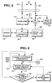
- Fig. 3 is a flowchart illustrating one method used for adapting the system antenna configuration between alternative antenna patterns.
- Figs. 6 and 7 illustrate overhead views of alternate antenna patterns to which the present embodiment of the system may be adapted.
- the second of the two embodiments shown in Fig. 2 is best described with reference also to Figs. 3, 6, and 7.
- a comparator block 235 is included within the arrangement and comprises a signal strength comparator 250 connected between a memory device 240 and a switch controller 260.
- the comparator 250 initially instructs the switch controller 260 to set the switch 220 in a position which removes phase shifter 230 from the circuit.
- the antenna elements 102, 102' are thus in phase, and an antenna pattern similar to that shown in Fig.
- the comparator 250 measures the signal strength of the signal received from the transmitting base station.
- the comparator 250 may be controlled either by a microprocessor, or by firmware or hardware.
- the switch controller 260 may optionally be microprocessor or firmware/hardware controlled, and may also provide system control in lieu of the comparator 250.
- the comparator 250 receives a sample of the received signal and stores a value representing the signal strength thereof in the memory device 240. On the initial pass through the flowchart, path 313 is taken, which loops back to step 330.
- the comparator 250 instructs the switch controller 260 to set the switch 220 in a position which connects the phase shifter 230 back into the circuit, between the antenna element 102' and the transceiver 210.
- the antenna elements 102, 102' are now out of phase, and an antenna pattern similar to that shown in Fig. 7 is generated.
- the phase shift imparted by phase shifter 230 is approximately 180 degrees to provide an antenna pattern having lobes which are oriented 90 degrees relative to the in-phase antenna pattern.
- the comparator 250 again measures the signal strength of the signal received from the transmitting base station. At this point, and in all subsequent passes through the flowchart, path 312 is taken to step 320.
- the comparator 250 compares the strength of the present received signal with the value of the previous signal stored in the memory 240. If the present signal strength is greater than the stored value, then the presently selected antenna pattern is the desired one, and the system waits a predetermined time, at step 340, before again determining which antenna configuration is to be selected.
- a cellular communications transceiver operating in accordance with the present invention scans for the direction of signals transmitted from a base station and selects the transceiver antenna pattern which more efficiently receives and radiates RF energy in the general direction of the base station.
- Fig. 4 is hardware block diagram illustrating two further alternative embodiments of the present cellular transceiver system, both of which utilize detection of a particular "message" from the base station.
- the mobile transceiver attempts to adapt the antenna configuration when a handoff message is detected by the transceiver electronics.
- two messages are sent from the base station to the mobile transceiver to allow the transceiver to determine the more advantageous direction in which to direct the antenna.
- a handoff protocol is used to transmit a handoff message to a succeeding said base station in an adjacent cell when the signal from said transceiver is stronger in the adjacent cell than in the cell presently communicating with the transceiver.
- the transceiver antenna direction may need to be changed when the handoff is made, so that the transceiver antenna pattern is directed toward the new base station.
- this is accomplished by the cellular transceiver which monitors the inter-cell handoff communications.
- the transceiver attempts to adapt the antenna configuration whenever a handoff is detected. This method is "passive" insofar as the base station is concerned, as there is no special adaptive antenna communications protocol directed to the mobile transceiver.
- a message detection circuit 420 is coupled to an adaptive antenna system similar to that described with respect to Figs. 2 and 3.
- the principle of antenna configuration adaptation of the system shown in Fig. 4 is essentially the same as that shown in Fig. 2, therefore, only the different operational particularities of the present embodiment are described in detail here.
- microprocessor/memory circuit 240/245 is optional if the comparator 250 or the switch controller 460 has internal firmware (or an internal microprocessor) and memory sufficient to control system operation. If the microprocessor 240 is present, then it is connected to the message detection circuit 420, as well as the comparator 250 and the switch controller 460.
- the message detection circuit 420 receives signals from both antenna elements 102 and 102'. Signals received from element 102' pass through the switch 220, which either directs the signals through the phase shifter 230, or allows the signals to pass directly to the message detection circuit 420, in which case the signals are in phase with those from the antenna element 102.
- an initial signal strength value is stored either in the optional comparator memory 255, or in the microprocessor memory 245, if a separate microprocessor is employed. This signal strength value represents the signal strength of the transmission received from the presently transmitting base station using the existing transceiver antenna configuration.
- the message detection circuit 420 causes the switch controller 460 to toggle the switch 220 which, in turn, causes the antenna 101 to generate an alternative antenna pattern.
- the comparator 250 compares the present signal strength with the value stored for the previous antenna configuration. If the present antenna pattern results in a stronger received signal than the previous pattern, then the antenna configuration remains fixed until the next handoff is detected. If, however, the present antenna pattern results in a weaker received signal than the previous pattern, the comparator 250 instructs switch controller 460 to switch the present antenna configuration back to the previous configuration until the next handoff is detected.
- the message detection circuit 420 communicates via the microprocessor to the switch controller 460, and the comparator 250 uses the microprocessor memory 245 to store the signal strength values.
- a special protocol can be introduced to allow the transceiver antenna to adapt to the preferable configuration.
- an "adaptation message" from the base station is repeated twice in a predetermined time interval so that the cellular phone receives the message with the antenna aiming in each of the two directions.
- the antenna is then set to provide maximum directionality in the direction of the strongest signal from the base station.
- this method requires an additional component of the base station protocol specifically directed to the mobile transceiver. This method is useful for providing antenna direction orientation when the base station is not otherwise transmitting a signal on which the mobile transceiver can "home in".
- the present system can utilize a message detection circuit 420 to detect the occurrence of an adaptation message transmitted from a base station.
- a signal strength value is stored either in the optional comparator memory 255, or in the microprocessor memory 245, if a separate microprocessor is employed. This signal strength value represents the signal strength of the transmission received from the presently transmitting base station using the existing transceiver antenna configuration.
- the message detection circuit 420 causes the switch controller 460 to toggle the switch 220 which, in turn, causes the antenna system 101 to exhibit an alternate antenna pattern.
- the comparator 250 compares the present signal strength with the value stored for the previous antenna configuration. If the present antenna pattern results in a stronger received signal than the previous pattern, then the antenna configuration remains fixed until the next adaptation message is detected. If, however, the present antenna pattern results in a weaker received signal than the previous pattern, then comparator 250 signals switch controller 460 to switch the present antenna configuration back to the previous configuration until the next adaptation message is detected.
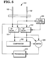
- Fig. 5 is a hardware block diagram of an embodiment employing two RF front end receivers ("front ends") 510, 510'.
- a phase shifter 230 is hardwired into the system to provide a fixed phase difference, typically 180 degrees, between the signals input to, and output from, the front ends 510, 510'.
- the signals from the antenna elements 102, 102' are processed by the front ends 510, 510', respectively, at the same time.
- no special protocol or message is required, as the comparator 250 measures the signal strength from both antenna configurations and instructs the switch 220 to select the configuration providing the stronger signal, which is applied to the transceiver 210.
- two (or more) different antennas with fixed patterns can be used, each pointing in a different direction.
- Figs. 6 and 7 show a pair of corresponding antenna patterns obtained by changing the phase of the signals transmitted or received by the two monopole antenna elements.
- Fig. 6 is an overhead view of an antenna system having monopole elements 602, 602' separated by spacing SP1, which is preferably one-half wavelength of the transmitted/ received signal. It can be seen that lobes 610, 610' are oriented along an East/West (E/W) axis, and nulls N1, N2 are oriented along a North/South (N/S) axis. This antenna pattern is generated when the signals received by or applied to elements 602 and 602' are in phase with each other.
- E/W East/West
- N1 North/South
- Fig. 7 is another overhead view of the antenna system shown in Fig. 6. It can be seen that lobes 610, 610' are oriented along the N/S axis, and nulls N3, N4 are oriented along the E/W axis. This antenna pattern is generated when the signals received by, or applied to, the elements 602 and 602' are 180 degrees out-of-phase with each other.
- the antenna system depicted in Figs. 6 and 7 is essentially "bi-directional".
- the antenna pattern is chosen which maximizes return signal from the base station with which the portable device is communicating. This signal maximization is accomplished by using each of the available antenna patterns and measuring the amount of signal power received at the cellular phone from the base station for each antenna pattern configuration.
- Fig. 8 is an overhead view of an antenna pattern realizable by using a pair of dipole elements.
- the cardioid antenna pattern thus generated is typically more directional than the pattern generated by a monopole element pair such as illustrated in Figs 6-7.
- dipole elements 802, 802' are separated by a spacing SP2, which is typically 1/4 wavelength.
- SP2 typically 1/4 wavelength.
- a resultant cardioid pattern 810 is generated.
- the applied signal is 90 degrees out-of-phase, for example, the antenna pattern shown in Fig. 8 is generated.
- the direction of the main lobe 810 exhibits a corresponding rotational displacement about point C.
- Fig. 8 As can be seen from Fig.
- such a cardioid antenna pattern is substantially unidirectional, with a main lobe 810 in direction N in this case.
- the elements 802 and 802' could be monopoles, instead of dipoles.
- an alternative antenna pattern could be selected wherein a null is directed toward the user of the transceiver, so as to minimize the radiated RF energy in the direction of the user.
- the present method is functional with any number of monopole or dipole elements whose spacing and phase relationship permits generation of more than two alternative configurations.
Abstract
Description
- The present invention relates to antenna apparatus and in particular, to a method and apparatus employing adaptive antenna pattern technology to provide improved signal directionality to reduce the power required for communication by a mobile or remote transceiver.
- U.S. Patent No. 5,260,968 to Gardner et al. discloses a method for "multiplexing radio communication signals," and uses "blind adaptive spatial filtering of spectrally overlapping signals." This method employs "self [spectral] coherence restoral" techniques which require complicated digital signal processing apparatus to provide the autocorrelation functions necessary to implement the method. Gardener's "adaptive" antenna array is situated at the base station, rather than at the mobile site.
- U.S. Patent No. 4,298,873 to Roberts discloses an adaptive antenna which steers toward nulls on an interference source. Roberts' method requires relatively complex hardware to implement the delay line adjustment and amplitude balance necessary for operation of the "null antenna processor."
- The present invention seeks to provide for an antenna apparatus and method having advantages over known apparatus and methods.
- In accordance with one aspect of the present invention there is provided antenna apparatus comprising antenna means connected to a transceiver means for receiving a first signal from a remote station and for transmitting a second signal to said remote station, and characterised in that said antenna means is adaptable to generate at least one of a plurality of antenna patterns having different directionality, and in that switch means operable with said antenna means is provided for selecting one of said antenna patterns which provides maximum signal strength of said first signal received from said remote station.
- Preferably said different antenna patterns have mutually exclusive directions.
- In accordance with another aspect of the present invention there is provided a method for directionally adapting antenna apparatus characterised by the steps of receiving, via an antenna having at least two monopole elements a first signal from said remote station and transmitting a second signal to said remote station, determining an optimum antenna patterns which provides a maximum signal amplitude of said first signal received from said remote station and establishing a desired signal phase relationship between each of said monopole elements to generate said optimum antenna pattern.
- It should be noted that the method of the present invention can advantageously teach away from the known methods such as Roberts by seeking signal maximums in a received signal.
- The invention can prove particularly advantageous in employing an adaptive directional multiple-monopole antenna system.
- In accordance with each of a plurality of embodiments of the present invention, a system can advantageously be provided which reduces the power consumption of a cellular phone or other similar remote transceiver. In each of these embodiments an adaptive directional antenna is used to radiate RF power in the direction of the cellular phone (or other) base station instead of radiating the RF power omnidirectionally. The directionality of the antenna is useful for reception as well as transmission, because it increases the strength of the received signal and reduces the amount of noise picked up by the cellular transceiver. The present system is particularly well suited to portable computing applications, such as those using a laptop computer or other remote computing device such as a "personal digital assistant".
- One exemplary embodiment of the present system includes a simple adaptive antenna system which can be switched, either manually or via microprocessor, to direct the radiated RF energy into, for example, quadrants or hemispheres in the vicinity of a communicating base station or satellite. This system saves transceiver battery power and compensates for large changes in orientation of the mobile transceiver with respect to the base station/satellite while maximizing signal gain between the transceiver and the base station/satellite.
- In a typical cellular phone system, a "handoff protocol" is used to transfer the communication link from one base station to another when the cellular phone (or other transceiver) signal passes from one cell to another cell in the cellular network. In a similar fashion, this same technique may be used to transfer the communication link from one orbiting satellite to another. An alternative embodiment of the present system changes the direction of the transceiver antenna direction to direct the antenna pattern toward the new base station/satellite when a handoff is made.
- In yet another embodiment of the present system, the transfer of communications from one cell to another is accomplished via the handoff protocol itself, wherein the cellular phone adapts the antenna configuration whenever a handoff is detected via the communication received from the base station.
- Another alternative embodiment of the present system periodically scans for the direction of the strongest return signal. Thus when a handoff is made, the cellular phone automatically adapts the antenna pattern at the next periodic direction scan.
- Further additional embodiments of the present invention encompass a variety of directional antenna designs whose radiation patterns can be adapted by changing the phase of the feed signals to different antenna elements. Because space is typically limited in and around mobile computing devices, the antenna may be limited to two elements (for instance, two monopoles mounted on the ends of a notebook computer). Furthermore, since wide antenna pattern lobes are desirable, a simple two-monopole adaptive antenna is well suited to the present system.
- A number of portable cellular devices are presently commercially available. Since all of these portable devices are typically battery powered, the operating period of each device is limited by the battery "life" available between successive recharges. Because the life of a given battery is extended by reducing the power consumption of the device connected to the battery, it follows that reducing the power consumption of a battery powered cellular phone device is highly desirable.
- In accordance with each one of a plurality of embodiments of the present invention, methods are provided for adapting an antenna pattern of a remote/mobile cellular transceiver to receive and transmit signals between a base station or satellite and the transceiver so as to establish an energy efficient communication path from the transceiver to the base station. The invention described herein is applicable to either base stations or satellites. The remaining description will describe the use of "base stations", however these techniques are similarly applicable to satellites as well.
- Therefore, it is an object of the present invention to reduce the power consumption of a cellular phone or other similar transceiver to provide the advantage of extending the operating life of the transceiver battery.
- The present system is particularly advantageous in that the reduction of transceiver power consumption requires only minimal hardware enhancements to existing cellular transceiver systems.
- A further advantage of the present invention is that the system enhances the signal-to-noise (S/N) ratio of the signal transmitted (by a transceiver) to a cellular base station, as well as the signal-to-noise ratio of the signals received (by the transceiver) from the base station.
- The antenna patterns of the present invention can preferably be bi-directional and can comprise, substantially, two opposingly situated lobes.
- The antenna patterns may alternatively merely comprise a unidirectional lobe.
- The invention is described further hereinafter, by way of example only, with reference to the accompanying drawings in which:
- Fig. 1 illustrates an embodiment of the present system wherein two monopole antennas are mounted near the ends of a portable computer;
- Fig. 2 is hardware block diagram illustrating one exemplary embodiment of the present invention;
- Fig. 3 is a flowchart illustrating one method used for adapting the system antenna configuration;
- Fig. 4 is hardware block diagram illustrating two further alternative embodiments of the present invention;
- Fig. 5 is a hardware block diagram of an embodiment employing two RF front ends;
- Figs. 6 and 7 illustrate overhead views of alternative antenna patterns to which one version of the system may be adapted; and
- Fig. 8 shows an overhead view of a cardioid antenna pattern realizable with the present invention.
- The present invention can use a directional antenna connected to a portable cellular communications transceiver to adaptively direct the antenna pattern towards a base station in a cellular communication system. The term "cellular communications transceiver," as used in the present application can include any form of mobile or remote transceiver such as a cellular telephone, 2-way pager, wireless LAN or mobile computer using a cellular communications network.
- A wide variety portable cellular devices are currently available. For example, PCMCIA ["PC Memory Card International Association"] cards are now available with cellular phone functions built in, and the EO PDA [Personal Digital Assistant] can have a cellular phone option.
- Typical cellular phones, for example, use a single monopole antenna and radiate approximately 600 milliwatts of RF power in an omnidirectional pattern in a horizontal plane. A simple directional antenna can easily have a gain of approximately 3dB over that of a monopole antenna. By replacing a single monopole with two monopoles, the radiated power can be reduced to 300 milliwatts, while maintaining the same power density in the direction of the base station.
- Since a mobile transceiver changes orientation with respect to cellular phone base stations, if a directional antenna is employed, it must be made directionally adaptive to provide an optimum communications path. One exemplary embodiment of the present system includes a simple adaptive directional antenna system which can direct the RF energy into selected quadrants or hemispheres to allow large changes in orientation relative to a base station while minimizing signal loss. Figs. 6-8, described in detail below, illustrate several possible antenna patterns which can be employed by the system to provide the required directionality.
- Fig. 1 shows an embodiment of the present system having an
antenna system 101 which uses twomonopole antennas 102, 102' mounted near the ends of aportable computer 100. Asimilar antenna system 101 employing dual-monopole antennas could also be used with mobile or remote transceivers such as cellular telephones, 2-way pagers, and wireless LANs (not shown). - Fig. 2 is hardware block diagram illustrating two possible embodiments of a dual-monopole version of the present system. As shown in Fig. 2, the
antenna system 101 comprises twomonopole elements 102, 102'. Theantenna element 102 is connected to atransceiver 210, and the antenna element 102' is connected to both aswitch 220 and aphase shifter 230. In the simpler of the two embodiments of Fig. 2, anoptional comparator block 235 is not used, and amanual switch 220 is used to select alternative antenna patterns by switchingphase shifter 230 either in series withtransceiver 210 or switching thephase shifter 230 out of the circuit. A transceiver operator may toggleswitch 220 to achieve the maximum audio volume, in the case of a cellular phone, for example. Optionally, an operator maytoggle switch 220 by referring to asignal strength meter 215 to adapt the antenna to the superior configuration, where a non-audio cellular device is used. - Fig. 3 is a flowchart illustrating one method used for adapting the system antenna configuration between alternative antenna patterns. Figs. 6 and 7 illustrate overhead views of alternate antenna patterns to which the present embodiment of the system may be adapted. The second of the two embodiments shown in Fig. 2 is best described with reference also to Figs. 3, 6, and 7. In this embodiment, a
comparator block 235 is included within the arrangement and comprises asignal strength comparator 250 connected between amemory device 240 and aswitch controller 260. In operation, atstep 305, thecomparator 250 initially instructs theswitch controller 260 to set theswitch 220 in a position which removesphase shifter 230 from the circuit. Theantenna elements 102, 102' are thus in phase, and an antenna pattern similar to that shown in Fig. 6 is generated. Atstep 310, thecomparator 250 measures the signal strength of the signal received from the transmitting base station. Thecomparator 250 may be controlled either by a microprocessor, or by firmware or hardware. Theswitch controller 260 may optionally be microprocessor or firmware/hardware controlled, and may also provide system control in lieu of thecomparator 250. Atstep 310, thecomparator 250 receives a sample of the received signal and stores a value representing the signal strength thereof in thememory device 240. On the initial pass through the flowchart,path 313 is taken, which loops back tostep 330. - At
step 330, thecomparator 250 instructs theswitch controller 260 to set theswitch 220 in a position which connects thephase shifter 230 back into the circuit, between the antenna element 102' and thetransceiver 210. Theantenna elements 102, 102' are now out of phase, and an antenna pattern similar to that shown in Fig. 7 is generated. The phase shift imparted byphase shifter 230 is approximately 180 degrees to provide an antenna pattern having lobes which are oriented 90 degrees relative to the in-phase antenna pattern. Atstep 310, thecomparator 250 again measures the signal strength of the signal received from the transmitting base station. At this point, and in all subsequent passes through the flowchart,path 312 is taken to step 320. Atstep 320, thecomparator 250 compares the strength of the present received signal with the value of the previous signal stored in thememory 240. If the present signal strength is greater than the stored value, then the presently selected antenna pattern is the desired one, and the system waits a predetermined time, atstep 340, before again determining which antenna configuration is to be selected. - If, however, the present signal strength is greater than the previously stored value, then, at
step 330, thecomparator 250 instructs theswitch controller 260 to set theswitch 220 in a position which connects thephase shifter 230 back to the alternate position, causing the alternative antenna pattern to be generated. In this case, after thecomparator 250 executessteps - Fig. 4 is hardware block diagram illustrating two further alternative embodiments of the present cellular transceiver system, both of which utilize detection of a particular "message" from the base station. In the first of these embodiments, the mobile transceiver attempts to adapt the antenna configuration when a handoff message is detected by the transceiver electronics. In the second embodiment, two messages are sent from the base station to the mobile transceiver to allow the transceiver to determine the more advantageous direction in which to direct the antenna.
- In normal operation of a typical cellular phone system, only a single base station is within receiving range of the cellular transceiver. However, when the cellular phone approaches the boundary of a cell, at least two base stations will be within range. In a typical cellular phone system, a handoff protocol is used to transmit a handoff message to a succeeding said base station in an adjacent cell when the signal from said transceiver is stronger in the adjacent cell than in the cell presently communicating with the transceiver. In the present case, wherein a cellular phone system is used with an adaptive antenna, the transceiver antenna direction may need to be changed when the handoff is made, so that the transceiver antenna pattern is directed toward the new base station. In a further alternative embodiment of the present system, this is accomplished by the cellular transceiver which monitors the inter-cell handoff communications. The transceiver attempts to adapt the antenna configuration whenever a handoff is detected. This method is "passive" insofar as the base station is concerned, as there is no special adaptive antenna communications protocol directed to the mobile transceiver.
- As shown in Fig. 4, which employs similar reference numerals for components similar to those of Fig. 2, a
message detection circuit 420 is coupled to an adaptive antenna system similar to that described with respect to Figs. 2 and 3. The principle of antenna configuration adaptation of the system shown in Fig. 4 is essentially the same as that shown in Fig. 2, therefore, only the different operational particularities of the present embodiment are described in detail here. It should be noted that microprocessor/memory circuit 240/245 is optional if thecomparator 250 or theswitch controller 460 has internal firmware (or an internal microprocessor) and memory sufficient to control system operation. If themicroprocessor 240 is present, then it is connected to themessage detection circuit 420, as well as thecomparator 250 and theswitch controller 460. - In operation, the
message detection circuit 420 receives signals from bothantenna elements 102 and 102'. Signals received from element 102' pass through theswitch 220, which either directs the signals through thephase shifter 230, or allows the signals to pass directly to themessage detection circuit 420, in which case the signals are in phase with those from theantenna element 102. In the present embodiment, an initial signal strength value is stored either in theoptional comparator memory 255, or in themicroprocessor memory 245, if a separate microprocessor is employed. This signal strength value represents the signal strength of the transmission received from the presently transmitting base station using the existing transceiver antenna configuration. When an inter-cell handoff message is received by the transceiver, themessage detection circuit 420 causes theswitch controller 460 to toggle theswitch 220 which, in turn, causes theantenna 101 to generate an alternative antenna pattern. Thecomparator 250 then compares the present signal strength with the value stored for the previous antenna configuration. If the present antenna pattern results in a stronger received signal than the previous pattern, then the antenna configuration remains fixed until the next handoff is detected. If, however, the present antenna pattern results in a weaker received signal than the previous pattern, thecomparator 250 instructsswitch controller 460 to switch the present antenna configuration back to the previous configuration until the next handoff is detected. - It should be noted that if the
microprocessor 240 is used, then themessage detection circuit 420 communicates via the microprocessor to theswitch controller 460, and thecomparator 250 uses themicroprocessor memory 245 to store the signal strength values. - During periods in which there is no transmission from the base station, a special protocol can be introduced to allow the transceiver antenna to adapt to the preferable configuration. In a further alternative embodiment of the present invention, an "adaptation message" from the base station is repeated twice in a predetermined time interval so that the cellular phone receives the message with the antenna aiming in each of the two directions. The antenna is then set to provide maximum directionality in the direction of the strongest signal from the base station. Unlike the handoff protocol detection described above, this method requires an additional component of the base station protocol specifically directed to the mobile transceiver. This method is useful for providing antenna direction orientation when the base station is not otherwise transmitting a signal on which the mobile transceiver can "home in".
- The principle of operation of the "adaptation message" embodiment is similar to that of the "handoff message" embodiment described above, therefore, only the different operational particularities of the present embodiment are described in detail. As shown in Fig. 4, the present system can utilize a
message detection circuit 420 to detect the occurrence of an adaptation message transmitted from a base station. In operation, when an adaptation message is received by the transceiver, a signal strength value is stored either in theoptional comparator memory 255, or in themicroprocessor memory 245, if a separate microprocessor is employed. This signal strength value represents the signal strength of the transmission received from the presently transmitting base station using the existing transceiver antenna configuration. Immediately thereafter, themessage detection circuit 420 causes theswitch controller 460 to toggle theswitch 220 which, in turn, causes theantenna system 101 to exhibit an alternate antenna pattern. When the second adaptation message is detected, thecomparator 250 compares the present signal strength with the value stored for the previous antenna configuration. If the present antenna pattern results in a stronger received signal than the previous pattern, then the antenna configuration remains fixed until the next adaptation message is detected. If, however, the present antenna pattern results in a weaker received signal than the previous pattern, then comparator 250 signals switchcontroller 460 to switch the present antenna configuration back to the previous configuration until the next adaptation message is detected. - Fig. 5 is a hardware block diagram of an embodiment employing two RF front end receivers ("front ends") 510, 510'. As shown in Fig. 5, a
phase shifter 230 is hardwired into the system to provide a fixed phase difference, typically 180 degrees, between the signals input to, and output from, the front ends 510, 510'. In operation, the signals from theantenna elements 102, 102' are processed by the front ends 510, 510', respectively, at the same time. In this case no special protocol or message is required, as thecomparator 250 measures the signal strength from both antenna configurations and instructs theswitch 220 to select the configuration providing the stronger signal, which is applied to thetransceiver 210. Alternatively, two (or more) different antennas with fixed patterns can be used, each pointing in a different direction. - There are many directional antenna designs whose radiation patterns can be adapted by changing the phase of the feed signals to different antenna elements. Because space is limited in mobile computing devices, the antenna may be limited to 2 or 3 elements (for instance, two monopoles mounted on the ends of a portable computer). Because wide antenna pattern lobes are desirable, a simple adaptive antenna having two monopole elements is well suited to this application. Figs. 6 and 7 show a pair of corresponding antenna patterns obtained by changing the phase of the signals transmitted or received by the two monopole antenna elements.
- Fig. 6 is an overhead view of an antenna system having
monopole elements 602, 602' separated by spacing SP1, which is preferably one-half wavelength of the transmitted/ received signal. It can be seen thatlobes 610, 610' are oriented along an East/West (E/W) axis, and nulls N1, N2 are oriented along a North/South (N/S) axis. This antenna pattern is generated when the signals received by or applied toelements 602 and 602' are in phase with each other. - Fig. 7 is another overhead view of the antenna system shown in Fig. 6. It can be seen that
lobes 610, 610' are oriented along the N/S axis, and nulls N3, N4 are oriented along the E/W axis. This antenna pattern is generated when the signals received by, or applied to, theelements 602 and 602' are 180 degrees out-of-phase with each other. The antenna system depicted in Figs. 6 and 7 is essentially "bi-directional". - Regardless of whether a dual monopole or dual dipole antenna system is employed, the antenna pattern is chosen which maximizes return signal from the base station with which the portable device is communicating. This signal maximization is accomplished by using each of the available antenna patterns and measuring the amount of signal power received at the cellular phone from the base station for each antenna pattern configuration.
- Fig. 8 is an overhead view of an antenna pattern realizable by using a pair of dipole elements. The cardioid antenna pattern thus generated is typically more directional than the pattern generated by a monopole element pair such as illustrated in Figs 6-7. As shown in Fig. 8,
dipole elements 802, 802' are separated by a spacing SP2, which is typically 1/4 wavelength. When an in-phase signal is applied toelements 802 and 802', a resultantcardioid pattern 810 is generated. When the applied signal is 90 degrees out-of-phase, for example, the antenna pattern shown in Fig. 8 is generated. As the relative phase between the dipole elements is changed, the direction of themain lobe 810 exhibits a corresponding rotational displacement about point C. As can be seen from Fig. 8, such a cardioid antenna pattern is substantially unidirectional, with amain lobe 810 in direction N in this case. In an alternative embodiment, theelements 802 and 802' could be monopoles, instead of dipoles. In a further alternative embodiment, regardless of whether theantenna elements 802, 802' are monopoles or dipoles, an alternative antenna pattern could be selected wherein a null is directed toward the user of the transceiver, so as to minimize the radiated RF energy in the direction of the user. - It should be noted that the present method is functional with any number of monopole or dipole elements whose spacing and phase relationship permits generation of more than two alternative configurations.
- The invention is not limited to the details of the foregoing embodiments but encompasses other modifications and alterations within the scope of the present inventive concept.
Claims (16)
- Antenna apparatus comprising antenna means (102,102') connected to a transceiver means (210) for receiving a first signal from a remote station and for transmitting a second signal to said remote station, and characterised in that said antenna means (102,102') is adaptable to generate at least one of a plurality of antenna patterns having different directionality, and in that switch means (220) operable with said antenna means (102,102'), is provided for selecting one of said antenna patterns which provides maximum signal strength of said first signal received from said remote station.
- Apparatus as claimed in Claim 1, wherein said switch means (220) is manually operable.
- Apparatus as claimed in Claim 1 or 2, wherein said antenna means (102,102') comprises two monopole antennas, and said system further includes phase shift means (230) operable with said switch means (220) for establishing a desired signal phase relationship between the two monopole antennas to adapt said antenna means (102,102') so as to generate a desired one of said antenna patterns.
- Apparatus as claimed in Claim 1 or 2, wherein said antenna means (102,102') comprises more than two monopole antennas, and phase shift means (230) are provided operable with said switch means (220) for establishing a desired signal phase relationship between said monopole antennas.
- Apparatus as claimed in Claim 1, wherein said antenna means (102,102') comprises two monopole elements, and the apparatus further includes comparator means (250) connected to said antenna means (102,102') and operable by way of said switch means (220) for determining an optimum one of said antenna patterns which provides a maximum signal amplitude of said first signal received from said remote station, phase shift means (230) connected to said antenna means (102,102') for establishing a desired signal phase relationship between each of said monopole elements; and wherein said switch means is responsive to said comparator means (250) and operable with said phase shift means (230) for selecting the antenna pattern (250) which provides maximum signal strength of said first signal received from said remote station.
- Apparatus as claimed in any one of Claims 1 to 5, wherein said switch means (220) can periodically select each of said antenna patterns in a cyclical fashion to determine which one of said antenna patterns provides said maximum signal strength of said first signal received from said remote station.
- Apparatus as claimed in any one of Claims 1 to 6, wherein said second signal is transmitted via the one of said antenna patterns used to receive the most recent said first signal.
- Apparatus as claimed in any one of Claims 1 to 7, wherein said plurality of antenna patterns comprises two antenna patterns wherein each of said antenna patterns is bidirectional and consists substantially of two opposingly situated lobes, each of said antenna patterns is oriented approximately 90 degrees to each other, a first one of said antenna patterns is generated by establishing a first phase relationship of 0 degrees, and a second one of said antenna patterns is generated by establishing a second said phase relationship of 180 degrees.
- Apparatus as claimed in Claim 4 or 5, wherein said plurality of antenna patterns comprises antenna N patterns in which each of said antenna patterns consists substantially of a unidirectional lobe oriented approximately 360/N degrees to an adjacent lobe, and each of said antenna patterns is generated by establishing an appropriate phase relationship between the antennas.
- Apparatus as claimed in any one of Claims 1 to 9, wherein said remote station periodically transmits a locator message pair comprising a first instance of a locating message followed by a second instance of said locating message, and further comprising memory means (255) for storing a signal strength value detection means (420) interconnected between said antenna means (102,102') and said switch means (220) for detecting said first instance of said locating message, storing a value representing the signal strength of said first instance in said memory means (255), causing said switch means (220) to select an alternate one of said antenna patterns in response to detection of said first locating message, and for detecting said second instance of said locating message, and wherein said comparator means (250) is arranged to compare said value stored in said memory means (255) with the signal strength of said second instance, and to operate said switch means (220) to select one of the antenna patterns which provides greater signal strength of said locating message.
- Apparatus as claimed in any one of Claims 1 to 9, wherein said remote station comprises a base station located in a first cell of a cellular communications network, and wherein a handoff protocol is used to transmit a handoff message to a succeeding base station in a second cell of said network when said second signal from said transceiver is stronger in said second cell than in said first cell, said apparatus further including memory means (255) for storing a signal strength value, detection means (420) interconnected between said antenna means (102, 102') and said switch means (220) for detecting said handoff message, storing a value representing the signal strength of said first signal in said memory, and causing said switch means (220) to select an alternative one of said antenna patterns in response to said detected message, and wherein said comparator means (250) is arranged to compare said value stored in said memory means (255) with the signal strength of said first signal received by said alternative one of said antenna patterns and to operate said switch means (220) to select one of the antenna patterns which provides greater signal strength of said first signal.
- Apparatus as claimed in any one of Claims 1-11, wherein said antenna means comprises two monopole antennas (102,102') having a first configuration in which a first phase relationship exists between said monopole elements and said apparatus further comprising phase shift means (230) for establishing a second configuration in which a second phase relationship exists between said monopole elements, comparator means (250) for determining a relative signal strength of two signals and two RF receiver means (510,510') each of which is connected between a different one of each of said antennas (102,102') and said comparator means (250), wherein said comparator means (250)operable with said switch means (220) to connect said transceiver (210) to the configuration which provides the stronger relative signal strength.
- A method for directionally adapting antenna apparatus characterised by the steps of receiving, via an antenna having at least two monopole elements (102,102') a first signal from a remote station and transmitting a second signal to said remote station, determining an optimum antenna pattern which provides a maximum signal amplitude of said first signal received from said remote station and establishing a desired signal phase relationship between each of said monopole elements to generate said optimum antenna pattern.
- A method as claimed in Claim 13 and including the step of periodically selecting each of said antenna patterns in a cyclical fashion to determine which said antenna pattern provides said maximum signal strength of said first signal received from said remote station.
- A method as claimed in Claim 13 or 14, wherein said remote station periodically transmits a locator message pair comprising a first instance of a locating message followed by a second instance of said locating message and including the step of periodically transmitting, from said remote station, a locator message pair consisting of a first instance of a locating message followed by a second instance of said locating message, and, at a transceiver site, detecting said first instance of said locating message, storing a value representing the signal strength of said first instance in memory selecting an alternative antenna pattern in response to detection of said first locating message, detecting said second instance of said locating message, comparing said value stored in said memory with the signal strength of said second instance, and selecting one of the antenna patterns which provides greater signal strength of said locating message.
- A method as claimed in Claim 13 or 14, wherein said remote station comprises a base station located in a first cell of a cellular communications system, and wherein a handoff protocol is used to transmit a handoff message to a succeeding base station in a second cell when said second signal from said transceiver is stronger in said second cell than in said first cell, and further including the steps of detecting said handoff message, storing a value representing the signal strength of said first signal in memory, selecting an alternative one of said antenna patterns in response to said detecting, comparing said value stored in said memory with the signal strength of said first signal received by said alternative one of said antenna patterns and selecting one of the antenna patterns which provides greater signal strength of said first signal.
Applications Claiming Priority (2)
| Application Number | Priority Date | Filing Date | Title |
|---|---|---|---|
| US08/342,328 US5617102A (en) | 1994-11-18 | 1994-11-18 | Communications transceiver using an adaptive directional antenna |
| US342328 | 1994-11-18 |
Publications (3)
| Publication Number | Publication Date |
|---|---|
| EP0713262A2 true EP0713262A2 (en) | 1996-05-22 |
| EP0713262A3 EP0713262A3 (en) | 1996-09-11 |
| EP0713262B1 EP0713262B1 (en) | 2011-03-02 |
Family
ID=23341352
Family Applications (1)
| Application Number | Title | Priority Date | Filing Date |
|---|---|---|---|
| EP95308223A Expired - Lifetime EP0713262B1 (en) | 1994-11-18 | 1995-11-16 | Antenna apparatus and direction method |
Country Status (5)
| Country | Link |
|---|---|
| US (1) | US5617102A (en) |
| EP (1) | EP0713262B1 (en) |
| JP (1) | JP3484277B2 (en) |
| KR (1) | KR100365303B1 (en) |
| DE (1) | DE69536146D1 (en) |
Cited By (12)
| Publication number | Priority date | Publication date | Assignee | Title |
|---|---|---|---|---|
| DE29613440U1 (en) * | 1996-08-02 | 1996-10-02 | Harfmann Alois | Alarm system |
| GB2307348A (en) * | 1995-11-13 | 1997-05-21 | Nec Corp | Communication apparatus with directional antenna system |
| EP0788284A1 (en) * | 1995-12-08 | 1997-08-06 | Nortel Networks Corporation | Scanning antenna for a communications system |
| WO1999005753A1 (en) * | 1997-07-22 | 1999-02-04 | Matsushita Communication Industrial (Uk) Ltd. | Telephone with multiple antenna configuration |
| EP0897230A2 (en) * | 1997-08-12 | 1999-02-17 | Fujitsu Limited | A wireless lan system and a transmitter-receiver in a wireless LAN system |
| EP0940934A2 (en) * | 1998-03-05 | 1999-09-08 | At&T Wireless Services, Inc. | FDD forward link beamforming method for a FDD communications system |
| EP1473840A1 (en) * | 2002-02-07 | 2004-11-03 | Mitsubishi Denki Kabushiki Kaisha | Radio communication apparatus |
| EP1657831A1 (en) * | 2003-08-21 | 2006-05-17 | Sony Corporation | Antenna and receiver apparatus using the same |
| WO2007048958A1 (en) * | 2005-10-27 | 2007-05-03 | Thomson Licensing | Transmitting/receiving antenna with radiation diversity |
| EP1835562A1 (en) * | 2004-12-08 | 2007-09-19 | Matsushita Electric Industrial Co., Ltd. | Adaptive antenna apparatus |
| US10244300B2 (en) | 2014-04-30 | 2019-03-26 | Oticon A/S | Instrument with remote object detection unit |
| EP3468229A1 (en) * | 2017-10-06 | 2019-04-10 | Oticon A/s | Instrument with remote object detection unit |
Families Citing this family (89)
| Publication number | Priority date | Publication date | Assignee | Title |
|---|---|---|---|---|
| US5708833A (en) * | 1993-04-27 | 1998-01-13 | Norand Corporation | Antenna cap, antenna connectors and telephone line connectors for computer devices utilizing radio and modem cards |
| US7119750B2 (en) * | 1993-04-27 | 2006-10-10 | Broadcom Corporation | Radio transceiver card communicating in a plurality of frequency bands |
| DE59611405D1 (en) * | 1995-01-20 | 2007-02-01 | Siemens Ag | DEVICE AND METHOD FOR ANTENNA SELECTION IN A CORDLESS TELEPHONE SYSTEM |
| US6018317A (en) * | 1995-06-02 | 2000-01-25 | Trw Inc. | Cochannel signal processing system |
| US5812777A (en) * | 1995-12-28 | 1998-09-22 | Compaq Computer Corporation | Remote terminal operation |
| US6219553B1 (en) * | 1997-03-31 | 2001-04-17 | Texas Instruments Incorporated | Low power wireless network using desktop antenna |
| US6081536A (en) | 1997-06-20 | 2000-06-27 | Tantivy Communications, Inc. | Dynamic bandwidth allocation to transmit a wireless protocol across a code division multiple access (CDMA) radio link |
| US6542481B2 (en) | 1998-06-01 | 2003-04-01 | Tantivy Communications, Inc. | Dynamic bandwidth allocation for multiple access communication using session queues |
| US6160510A (en) * | 1997-07-03 | 2000-12-12 | Lucent Technologies, Inc. | Delay line antenna array system and method thereof |
| US7936728B2 (en) | 1997-12-17 | 2011-05-03 | Tantivy Communications, Inc. | System and method for maintaining timing of synchronization messages over a reverse link of a CDMA wireless communication system |
| US9525923B2 (en) | 1997-12-17 | 2016-12-20 | Intel Corporation | Multi-detection of heartbeat to reduce error probability |
| US6222832B1 (en) | 1998-06-01 | 2001-04-24 | Tantivy Communications, Inc. | Fast Acquisition of traffic channels for a highly variable data rate reverse link of a CDMA wireless communication system |
| US7394791B2 (en) | 1997-12-17 | 2008-07-01 | Interdigital Technology Corporation | Multi-detection of heartbeat to reduce error probability |
| US7079523B2 (en) * | 2000-02-07 | 2006-07-18 | Ipr Licensing, Inc. | Maintenance link using active/standby request channels |
| WO1999034525A1 (en) * | 1997-12-24 | 1999-07-08 | Mitsubishi Denki Kabushiki Kaisha | Pda antenna system |
| US8134980B2 (en) | 1998-06-01 | 2012-03-13 | Ipr Licensing, Inc. | Transmittal of heartbeat signal at a lower level than heartbeat request |
| US7773566B2 (en) * | 1998-06-01 | 2010-08-10 | Tantivy Communications, Inc. | System and method for maintaining timing of synchronization messages over a reverse link of a CDMA wireless communication system |
| US6362790B1 (en) | 1998-09-18 | 2002-03-26 | Tantivy Communications, Inc. | Antenna array structure stacked over printed wiring board with beamforming components |
| US6792290B2 (en) * | 1998-09-21 | 2004-09-14 | Ipr Licensing, Inc. | Method and apparatus for performing directional re-scan of an adaptive antenna |
| US6933887B2 (en) * | 1998-09-21 | 2005-08-23 | Ipr Licensing, Inc. | Method and apparatus for adapting antenna array using received predetermined signal |
| US6600456B2 (en) | 1998-09-21 | 2003-07-29 | Tantivy Communications, Inc. | Adaptive antenna for use in wireless communication systems |
| US6400317B2 (en) | 1998-09-21 | 2002-06-04 | Tantivy Communications, Inc. | Method and apparatus for antenna control in a communications network |
| US6989797B2 (en) * | 1998-09-21 | 2006-01-24 | Ipr Licensing, Inc. | Adaptive antenna for use in wireless communication systems |
| US6100843A (en) * | 1998-09-21 | 2000-08-08 | Tantivy Communications Inc. | Adaptive antenna for use in same frequency networks |
| US6473036B2 (en) | 1998-09-21 | 2002-10-29 | Tantivy Communications, Inc. | Method and apparatus for adapting antenna array to reduce adaptation time while increasing array performance |
| US6404386B1 (en) | 1998-09-21 | 2002-06-11 | Tantivy Communications, Inc. | Adaptive antenna for use in same frequency networks |
| US6121925A (en) * | 1999-09-01 | 2000-09-19 | The United States Of America As Represented By The Secretary Of The Army | Data-link and antenna selection assembly |
| US6654616B1 (en) * | 1999-09-27 | 2003-11-25 | Verizon Laboratories Inc. | Wireless area network having flexible backhauls for creating backhaul network |
| KR100743450B1 (en) * | 1999-10-26 | 2007-07-30 | 코닌클리케 필립스 일렉트로닉스 엔.브이. | A primary radio station for use in a communication system, a method for controlling a multi-directional controllable antenna structure in such a primary radio station, and a computer program storage medium for use in such a primary radio station |
| US6917790B1 (en) | 1999-10-29 | 2005-07-12 | Amc Centurion Ab | Antenna device and method for transmitting and receiving radio waves |
| SE516535C2 (en) | 1999-10-29 | 2002-01-29 | Allgon Ab | Antenna device switchable between a plurality of configuration modes adapted for use in different operating environments and associated method |
| SE516536C2 (en) * | 1999-10-29 | 2002-01-29 | Allgon Ab | Antenna device switchable between a plurality of configuration states depending on two operating parameters and associated method |
| JP3750910B2 (en) * | 1999-12-13 | 2006-03-01 | セイコーインスツル株式会社 | Information processing apparatus and information processing method |
| WO2001058044A2 (en) | 2000-02-07 | 2001-08-09 | Tantivy Communications, Inc. | Minimal maintenance link to support synchronization |
| US7233627B2 (en) * | 2000-02-23 | 2007-06-19 | Ipr Licensing, Inc. | Method for searching pilot signals to synchronize a CDMA receiver with an associated transmitter |
| US6463090B1 (en) * | 2000-06-19 | 2002-10-08 | Bertrand Dorfman | Communication in high rise buildings |
| US6697642B1 (en) * | 2000-07-19 | 2004-02-24 | Texas Instruments Incorporated | Wireless communications apparatus |
| US6476773B2 (en) | 2000-08-18 | 2002-11-05 | Tantivy Communications, Inc. | Printed or etched, folding, directional antenna |
| US6606059B1 (en) * | 2000-08-28 | 2003-08-12 | Intel Corporation | Antenna for nomadic wireless modems |
| US6445688B1 (en) * | 2000-08-31 | 2002-09-03 | Ricochet Networks, Inc. | Method and apparatus for selecting a directional antenna in a wireless communication system |
| US6515635B2 (en) | 2000-09-22 | 2003-02-04 | Tantivy Communications, Inc. | Adaptive antenna for use in wireless communication systems |
| US7162273B1 (en) * | 2000-11-10 | 2007-01-09 | Airgain, Inc. | Dynamically optimized smart antenna system |
| US8155096B1 (en) | 2000-12-01 | 2012-04-10 | Ipr Licensing Inc. | Antenna control system and method |
| US6778844B2 (en) * | 2001-01-26 | 2004-08-17 | Dell Products L.P. | System for reducing multipath fade of RF signals in a wireless data application |
| US7551663B1 (en) | 2001-02-01 | 2009-06-23 | Ipr Licensing, Inc. | Use of correlation combination to achieve channel detection |
| US6954448B2 (en) | 2001-02-01 | 2005-10-11 | Ipr Licensing, Inc. | Alternate channel for carrying selected message types |
| US6864852B2 (en) * | 2001-04-30 | 2005-03-08 | Ipr Licensing, Inc. | High gain antenna for wireless applications |
| US6606057B2 (en) | 2001-04-30 | 2003-08-12 | Tantivy Communications, Inc. | High gain planar scanned antenna array |
| US6774852B2 (en) * | 2001-05-10 | 2004-08-10 | Ipr Licensing, Inc. | Folding directional antenna |
| US6480157B1 (en) | 2001-05-18 | 2002-11-12 | Tantivy Communications, Inc. | Foldable directional antenna |
| US6762722B2 (en) * | 2001-05-18 | 2004-07-13 | Ipr Licensing, Inc. | Directional antenna |
| US6788268B2 (en) * | 2001-06-12 | 2004-09-07 | Ipr Licensing, Inc. | Method and apparatus for frequency selective beam forming |
| ES2626289T3 (en) | 2001-06-13 | 2017-07-24 | Intel Corporation | Method and apparatus for transmitting heartbeat signal at a lower level than the heartbeat request |
| US20050102425A1 (en) * | 2001-11-22 | 2005-05-12 | Kitchen Martin H. | Method of handing over a terminal |
| US6987956B2 (en) * | 2001-11-30 | 2006-01-17 | Samsung Electronics Co., Ltd. | System and method for improving performance of an HDR wireless terminal with diversity |
| US6628235B2 (en) * | 2001-12-17 | 2003-09-30 | The Boeing Company | Method for phased array antenna signal handoff |
| AU2003224707A1 (en) * | 2002-03-14 | 2003-09-29 | Ipr Licensing, Inc. | Mobile communication handset with adaptive antenna array |
| US6816116B2 (en) | 2002-03-22 | 2004-11-09 | Quanta Computer, Inc. | Smart antenna for portable devices |
| KR20050026701A (en) * | 2002-05-07 | 2005-03-15 | 아이피알 라이센싱, 인코포레이티드 | Antenna adaptation in a time division duplexing system |
| US20030228857A1 (en) * | 2002-06-06 | 2003-12-11 | Hitachi, Ltd. | Optimum scan for fixed-wireless smart antennas |
| US7072718B2 (en) * | 2002-12-03 | 2006-07-04 | Cardiac Pacemakers, Inc. | Antenna systems for implantable medical device telemetry |
| JP4059762B2 (en) * | 2002-12-11 | 2008-03-12 | 富士通テン株式会社 | Directivity control device for in-vehicle antenna system |
| US7103386B2 (en) * | 2003-06-19 | 2006-09-05 | Ipr Licensing, Inc. | Antenna steering and hidden node recognition for an access point |
| US7587173B2 (en) * | 2003-06-19 | 2009-09-08 | Interdigital Technology Corporation | Antenna steering for an access point based upon spatial diversity |
| US7609648B2 (en) * | 2003-06-19 | 2009-10-27 | Ipr Licensing, Inc. | Antenna steering for an access point based upon control frames |
| US7047046B2 (en) * | 2003-06-19 | 2006-05-16 | Ipr Licensing, Inc. | Antenna steering for an access point based upon probe signals |
| KR20060119986A (en) * | 2003-11-24 | 2006-11-24 | 인터디지탈 테크날러지 코포레이션 | Method and apparatus for utilizing a directional beam antenna in a wireless transmit/receive unit |
| US7295811B2 (en) * | 2004-02-05 | 2007-11-13 | Interdigital Technology Corporation | Method for performing measurements for handoff of a mobile unit operating with a switched beam antenna in a wireless communication system, and corresponding system |
| US7274936B2 (en) * | 2004-02-06 | 2007-09-25 | Interdigital Technology Corporation | Method and apparatus for measuring channel quality using a smart antenna in a wireless transmit/receive unit |
| AU2005246674A1 (en) * | 2004-04-12 | 2005-12-01 | Airgain, Inc. | Switched multi-beam antenna |
| US7385561B2 (en) * | 2005-02-17 | 2008-06-10 | Galtronics Ltd. | Multiple monopole antenna |
| US7696940B1 (en) | 2005-05-04 | 2010-04-13 | hField Technologies, Inc. | Wireless networking adapter and variable beam width antenna |
| US7683757B2 (en) * | 2005-10-18 | 2010-03-23 | Lear Corporation | Multi-antenna system and method for remotely controlling a function |
| US8344956B2 (en) | 2007-04-20 | 2013-01-01 | Skycross, Inc. | Methods for reducing near-field radiation and specific absorption rate (SAR) values in communications devices |
| US7688273B2 (en) * | 2007-04-20 | 2010-03-30 | Skycross, Inc. | Multimode antenna structure |
| US7688275B2 (en) * | 2007-04-20 | 2010-03-30 | Skycross, Inc. | Multimode antenna structure |
| US8866691B2 (en) | 2007-04-20 | 2014-10-21 | Skycross, Inc. | Multimode antenna structure |
| JP2009033605A (en) * | 2007-07-30 | 2009-02-12 | Kyocera Corp | Radio communication terminal, radio communication system and communication method of radio communication terminal |
| WO2009035039A1 (en) * | 2007-09-13 | 2009-03-19 | Nec Corporation | Radio receiver and position calculation method |
| US8405549B2 (en) * | 2008-06-03 | 2013-03-26 | Hisep Technology Ltd. | Direction finding method and device |
| KR20100038790A (en) * | 2008-10-06 | 2010-04-15 | 삼성전자주식회사 | Method and apparatus for near field communication of portable terminal |
| US20120052821A1 (en) * | 2010-08-25 | 2012-03-01 | Dongxun Jia | Perturbation antenna system and apparatus for wireless terminals |
| US9692532B2 (en) * | 2012-02-10 | 2017-06-27 | Mediatek Inc. | Method and wireless communication device for antenna deployment determination |
| WO2013133931A1 (en) * | 2012-03-05 | 2013-09-12 | Xw Llc Dba Xtendwave | Multi-antenna receiver in a radio controlled clock |
| US10096910B2 (en) | 2012-06-13 | 2018-10-09 | Skycross Co., Ltd. | Multimode antenna structures and methods thereof |
| CN104885498A (en) * | 2012-12-27 | 2015-09-02 | 中兴通讯(美国)公司 | Method and system for ue measurements in support of mimo ota |
| US20150116161A1 (en) | 2013-10-28 | 2015-04-30 | Skycross, Inc. | Antenna structures and methods thereof for determining a frequency offset based on a signal magnitude measurement |
| US20160218426A1 (en) * | 2015-01-26 | 2016-07-28 | Nitero Pty Ltd. | Power management in wireless communications devices |
| JP6996574B2 (en) * | 2020-01-06 | 2022-01-17 | 株式会社デンソー | Battery pack |
Citations (2)
| Publication number | Priority date | Publication date | Assignee | Title |
|---|---|---|---|---|
| US4298873A (en) | 1981-01-02 | 1981-11-03 | The United States Of America As Represented By The Secretary Of The Army | Adaptive steerable null antenna processor |
| US5260968A (en) | 1992-06-23 | 1993-11-09 | The Regents Of The University Of California | Method and apparatus for multiplexing communications signals through blind adaptive spatial filtering |
Family Cites Families (26)
| Publication number | Priority date | Publication date | Assignee | Title |
|---|---|---|---|---|
| US3357018A (en) * | 1964-11-06 | 1967-12-05 | Itek Corp | Mode-averaging diversity combining reception system for high-frequency radio waves |
| US3737899A (en) * | 1971-02-01 | 1973-06-05 | Raytheon Co | Phased array antenna controller |
| US4032922A (en) * | 1976-01-09 | 1977-06-28 | The United States Of America As Represented By The Secretary Of The Navy | Multibeam adaptive array |
| US4103302A (en) * | 1976-07-16 | 1978-07-25 | General Electric Company | Velocity and drift angle tracking system using altimetry signals |
| US4378559A (en) * | 1980-12-05 | 1983-03-29 | The United States Of America As Represented By The Secretary Of The Army | Radar antenna system |
| GB2108327B (en) * | 1981-09-07 | 1985-04-24 | Nippon Telegraph & Telephone | Directivity diversity communication system |
| US4513412A (en) * | 1983-04-25 | 1985-04-23 | At&T Bell Laboratories | Time division adaptive retransmission technique for portable radio telephones |
| US4779138A (en) * | 1985-11-27 | 1988-10-18 | Casio Computer Co., Ltd. | Compact liquid crystal television receiver having information memory |
| US4710944A (en) * | 1986-10-17 | 1987-12-01 | Rca Corporation | Dual transmit-receive space diversity communication system |
| US4845507A (en) * | 1987-08-07 | 1989-07-04 | Raytheon Company | Modular multibeam radio frequency array antenna system |
| US4973952A (en) * | 1987-09-21 | 1990-11-27 | Information Resources, Inc. | Shopping cart display system |
| US5095535A (en) * | 1988-07-28 | 1992-03-10 | Motorola, Inc. | High bit rate communication system for overcoming multipath |
| JPH02186728A (en) * | 1989-01-13 | 1990-07-23 | Hitachi Ltd | Selective directional antenna |
| US4972457A (en) * | 1989-01-19 | 1990-11-20 | Spectrum Information Technologies, Inc. | Portable hybrid communication system and methods |
| US5305181A (en) * | 1989-05-15 | 1994-04-19 | Norand Corporation | Arm or wrist mounted terminal with a flexible housing |
| US4992799A (en) * | 1989-09-28 | 1991-02-12 | Motorola, Inc. | Adaptable antenna |
| JPH03210830A (en) * | 1990-01-12 | 1991-09-13 | Clarion Co Ltd | Directivity diversity receiver |
| FI85776C (en) * | 1990-08-20 | 1992-05-25 | Nokia Oy Ab | Portable personal workstation |
| US5117236A (en) * | 1990-10-19 | 1992-05-26 | Motorola, Inc. | Antenna pattern selection for optimized communications |
| JPH04246935A (en) * | 1991-01-31 | 1992-09-02 | Nec Corp | Communication channel switching test device |
| JP3081891B2 (en) * | 1991-04-19 | 2000-08-28 | 日本電信電話株式会社 | Antenna beam control method |
| JP2730810B2 (en) * | 1991-05-10 | 1998-03-25 | シャープ株式会社 | Information processing device |
| US5194873A (en) * | 1991-10-11 | 1993-03-16 | General Electric Company | Antenna system providing a spherical radiation pattern |
| US5281962A (en) * | 1992-05-08 | 1994-01-25 | Motorola, Inc. | Method and apparatus for automatic generation and notification of tag information corresponding to a received message |
| JP2874468B2 (en) * | 1992-08-21 | 1999-03-24 | 日本電気株式会社 | Portable wireless telephone |
| GB9304636D0 (en) * | 1993-03-06 | 1993-04-21 | Ncr Int Inc | A method of accessing a communication system |
-
1994
- 1994-11-18 US US08/342,328 patent/US5617102A/en not_active Expired - Lifetime
-
1995
- 1995-11-16 EP EP95308223A patent/EP0713262B1/en not_active Expired - Lifetime
- 1995-11-16 DE DE69536146T patent/DE69536146D1/en not_active Expired - Lifetime
- 1995-11-17 KR KR1019950041820A patent/KR100365303B1/en not_active IP Right Cessation
- 1995-11-20 JP JP30117095A patent/JP3484277B2/en not_active Expired - Fee Related
Patent Citations (2)
| Publication number | Priority date | Publication date | Assignee | Title |
|---|---|---|---|---|
| US4298873A (en) | 1981-01-02 | 1981-11-03 | The United States Of America As Represented By The Secretary Of The Army | Adaptive steerable null antenna processor |
| US5260968A (en) | 1992-06-23 | 1993-11-09 | The Regents Of The University Of California | Method and apparatus for multiplexing communications signals through blind adaptive spatial filtering |
Cited By (25)
| Publication number | Priority date | Publication date | Assignee | Title |
|---|---|---|---|---|
| US5719583A (en) * | 1995-11-13 | 1998-02-17 | Nec Corporation | Mobile communication system which performs antenna gain control |
| GB2307348A (en) * | 1995-11-13 | 1997-05-21 | Nec Corp | Communication apparatus with directional antenna system |
| GB2307348B (en) * | 1995-11-13 | 1999-11-10 | Nec Corp | Mobile communication system |
| US6150987A (en) * | 1995-12-08 | 2000-11-21 | Nortel Networks Limited | Antenna assembly |
| EP0788284A1 (en) * | 1995-12-08 | 1997-08-06 | Nortel Networks Corporation | Scanning antenna for a communications system |
| DE29613440U1 (en) * | 1996-08-02 | 1996-10-02 | Harfmann Alois | Alarm system |
| WO1999005753A1 (en) * | 1997-07-22 | 1999-02-04 | Matsushita Communication Industrial (Uk) Ltd. | Telephone with multiple antenna configuration |
| EP0897230A2 (en) * | 1997-08-12 | 1999-02-17 | Fujitsu Limited | A wireless lan system and a transmitter-receiver in a wireless LAN system |
| EP0897230A3 (en) * | 1997-08-12 | 1999-04-14 | Fujitsu Limited | A wireless lan system and a transmitter-receiver in a wireless LAN system |
| US7212510B2 (en) | 1997-08-12 | 2007-05-01 | Fujitsu Limited | Wireless LAN system and a transmitter-receiver in a wireless LAN system |
| US6359873B1 (en) | 1997-08-12 | 2002-03-19 | Fujitsu Limited | Wireless LAN system and a transmitter-receiver in a wireless LAN system |
| EP0940934A2 (en) * | 1998-03-05 | 1999-09-08 | At&T Wireless Services, Inc. | FDD forward link beamforming method for a FDD communications system |
| EP0940934A3 (en) * | 1998-03-05 | 2001-04-11 | At&T Wireless Services, Inc. | FDD forward link beamforming method for a FDD communications system |
| EP1473840A1 (en) * | 2002-02-07 | 2004-11-03 | Mitsubishi Denki Kabushiki Kaisha | Radio communication apparatus |
| EP1473840A4 (en) * | 2002-02-07 | 2005-03-09 | Mitsubishi Electric Corp | Radio communication apparatus |
| US7389127B2 (en) | 2002-02-07 | 2008-06-17 | Mitsubishi Denki Kabushiki Kaisha | Radio communication apparatus |
| EP1657831A1 (en) * | 2003-08-21 | 2006-05-17 | Sony Corporation | Antenna and receiver apparatus using the same |
| EP1657831A4 (en) * | 2003-08-21 | 2007-11-14 | Sony Corp | Antenna and receiver apparatus using the same |
| EP1835562A1 (en) * | 2004-12-08 | 2007-09-19 | Matsushita Electric Industrial Co., Ltd. | Adaptive antenna apparatus |
| EP1835562A4 (en) * | 2004-12-08 | 2008-12-03 | Panasonic Corp | Adaptive antenna apparatus |
| WO2007048958A1 (en) * | 2005-10-27 | 2007-05-03 | Thomson Licensing | Transmitting/receiving antenna with radiation diversity |
| FR2892862A1 (en) * | 2005-10-27 | 2007-05-04 | Thomson Licensing Sas | RADIATION DIVERSITY TRANSMITTING / RECEIVING ANTENNA |
| US7864126B2 (en) | 2005-10-27 | 2011-01-04 | Thomson Licensing | Transmitting/receiving antenna with radiation diversity |
| US10244300B2 (en) | 2014-04-30 | 2019-03-26 | Oticon A/S | Instrument with remote object detection unit |
| EP3468229A1 (en) * | 2017-10-06 | 2019-04-10 | Oticon A/s | Instrument with remote object detection unit |
Also Published As
| Publication number | Publication date |
|---|---|
| KR960019852A (en) | 1996-06-17 |
| DE69536146D1 (en) | 2011-04-14 |
| EP0713262A3 (en) | 1996-09-11 |
| US5617102A (en) | 1997-04-01 |
| EP0713262B1 (en) | 2011-03-02 |
| JPH08251099A (en) | 1996-09-27 |
| KR100365303B1 (en) | 2003-04-10 |
| JP3484277B2 (en) | 2004-01-06 |
Similar Documents
| Publication | Publication Date | Title |
|---|---|---|
| EP0713262B1 (en) | Antenna apparatus and direction method | |
| US8362968B2 (en) | Array antenna, radio communication apparatus, and array antenna control method | |
| US7268738B2 (en) | Beamforming using a backplane and passive antenna element | |
| JP3645948B2 (en) | Antenna structure and wireless communication apparatus incorporating the antenna structure | |
| KR100292008B1 (en) | Wireless Communication System and Communication Method Using Scanned Directional Antenna | |
| CA1220546A (en) | Homotropic antenna system for portable radio | |
| US7009559B2 (en) | Method and apparatus for adapting antenna array using received predetermined signal | |
| MXPA04004432A (en) | A dual band phased array employing spatial second harmonics. | |
| NO340372B1 (en) | Wireless Transmitter / Receiver Unit (WTRU) attenuation to WTRU interference using multiple antennas or beams | |
| WO1999027610A1 (en) | A communication system, a primary radio station, a secondary radio station, and a communication method | |
| US6297780B1 (en) | Mobile apparatus with plurality of antennas having different directivities | |
| EP1298825B1 (en) | Apparatus and method using smart antenna in fdd wireless communication system | |
| WO2001052445A1 (en) | Mobile radio unit | |
| EP1016157B1 (en) | Telephone with multiple antenna configuration | |
| WO1995034997A2 (en) | Diversity combining for antennas | |
| JP3513058B2 (en) | Mobile terminal device | |
| EP0881782A2 (en) | Maximum-ratio synthetic transmission diversity device | |
| US6476776B1 (en) | Satellite adaptive antenna system | |
| JPH10313472A (en) | Radio base station unit and radio terminal | |
| JP2000252734A (en) | Antenna system for base station for mobile communication | |
| US6219563B1 (en) | Method for signal transmission in a communication system between a mobile radio transmission/reception device and a stationary radio transmission/reception device | |
| US6484015B1 (en) | Portable telephone antenna | |
| CN115347345A (en) | Flexible screen terminal, antenna adjusting method and storage medium |
Legal Events
| Date | Code | Title | Description |
|---|---|---|---|
| PUAI | Public reference made under article 153(3) epc to a published international application that has entered the european phase |
Free format text: ORIGINAL CODE: 0009012 |
|
| AK | Designated contracting states |
Kind code of ref document: A2 Designated state(s): DE FR GB |
|
| PUAL | Search report despatched |
Free format text: ORIGINAL CODE: 0009013 |
|
| RHK1 | Main classification (correction) |
Ipc: H04B 7/08 |
|
| AK | Designated contracting states |
Kind code of ref document: A3 Designated state(s): DE FR GB |
|
| 17P | Request for examination filed |
Effective date: 19961004 |
|
| RAP1 | Party data changed (applicant data changed or rights of an application transferred) |
Owner name: SYMBIOS, INC. |
|
| RAP1 | Party data changed (applicant data changed or rights of an application transferred) |
Owner name: HYUNDAI ELECTRONICS AMERICA |
|
| 17Q | First examination report despatched |
Effective date: 20020708 |
|
| RAP1 | Party data changed (applicant data changed or rights of an application transferred) |
Owner name: HYNIX SEMICONDUCTOR INC. |
|
| RAP1 | Party data changed (applicant data changed or rights of an application transferred) |
Owner name: MAGNACHIP SEMICONDUCTOR, LTD. |
|
| GRAP | Despatch of communication of intention to grant a patent |
Free format text: ORIGINAL CODE: EPIDOSNIGR1 |
|
| GRAS | Grant fee paid |
Free format text: ORIGINAL CODE: EPIDOSNIGR3 |
|
| GRAA | (expected) grant |
Free format text: ORIGINAL CODE: 0009210 |
|
| AK | Designated contracting states |
Kind code of ref document: B1 Designated state(s): DE FR GB |
|
| REG | Reference to a national code |
Ref country code: GB Ref legal event code: FG4D |
|
| REF | Corresponds to: |
Ref document number: 69536146 Country of ref document: DE Date of ref document: 20110414 Kind code of ref document: P |
|
| REG | Reference to a national code |
Ref country code: DE Ref legal event code: R096 Ref document number: 69536146 Country of ref document: DE Effective date: 20110414 |
|
| PLBE | No opposition filed within time limit |
Free format text: ORIGINAL CODE: 0009261 |
|
| STAA | Information on the status of an ep patent application or granted ep patent |
Free format text: STATUS: NO OPPOSITION FILED WITHIN TIME LIMIT |
|
| 26N | No opposition filed |
Effective date: 20111205 |
|
| REG | Reference to a national code |
Ref country code: GB Ref legal event code: 732E Free format text: REGISTERED BETWEEN 20120301 AND 20120307 |
|
| REG | Reference to a national code |
Ref country code: DE Ref legal event code: R097 Ref document number: 69536146 Country of ref document: DE Effective date: 20111205 |
|
| PGFP | Annual fee paid to national office [announced via postgrant information from national office to epo] |
Ref country code: GB Payment date: 20141127 Year of fee payment: 20 Ref country code: DE Payment date: 20141128 Year of fee payment: 20 Ref country code: FR Payment date: 20141118 Year of fee payment: 20 |
|
| REG | Reference to a national code |
Ref country code: DE Ref legal event code: R071 Ref document number: 69536146 Country of ref document: DE |
|
| REG | Reference to a national code |
Ref country code: GB Ref legal event code: PE20 Expiry date: 20151115 |
|
| PG25 | Lapsed in a contracting state [announced via postgrant information from national office to epo] |
Ref country code: GB Free format text: LAPSE BECAUSE OF EXPIRATION OF PROTECTION Effective date: 20151115 |