EP0713316A2 - Wireless communication apparatus - Google Patents
Wireless communication apparatus Download PDFInfo
- Publication number
- EP0713316A2 EP0713316A2 EP95402587A EP95402587A EP0713316A2 EP 0713316 A2 EP0713316 A2 EP 0713316A2 EP 95402587 A EP95402587 A EP 95402587A EP 95402587 A EP95402587 A EP 95402587A EP 0713316 A2 EP0713316 A2 EP 0713316A2
- Authority
- EP
- European Patent Office
- Prior art keywords
- communication
- signal
- transmission
- wireless
- alarm signal
- Prior art date
- Legal status (The legal status is an assumption and is not a legal conclusion. Google has not performed a legal analysis and makes no representation as to the accuracy of the status listed.)
- Granted
Links
Images


Classifications
-
- H—ELECTRICITY
- H04—ELECTRIC COMMUNICATION TECHNIQUE
- H04M—TELEPHONIC COMMUNICATION
- H04M1/00—Substation equipment, e.g. for use by subscribers
- H04M1/72—Mobile telephones; Cordless telephones, i.e. devices for establishing wireless links to base stations without route selection
- H04M1/725—Cordless telephones
- H04M1/72502—Cordless telephones with one base station connected to a single line
- H04M1/72516—Cordless telephones with one base station connected to a single line with means for out-of-range alerting
-
- H—ELECTRICITY
- H04—ELECTRIC COMMUNICATION TECHNIQUE
- H04M—TELEPHONIC COMMUNICATION
- H04M1/00—Substation equipment, e.g. for use by subscribers
- H04M1/72—Mobile telephones; Cordless telephones, i.e. devices for establishing wireless links to base stations without route selection
- H04M1/725—Cordless telephones
- H04M1/72502—Cordless telephones with one base station connected to a single line
- H04M1/72505—Radio link set-up procedures
Definitions
- This invention relates to a wireless communication apparatus such as a cordless telephone, capable of communication by wireless communication means.
- carrier sensing in cordless telephones is performed independently by a main phone and a subphone. That is, the main phone monitors a carrier signal in radio waves emitted from the subphone, and if it becomes that the carrier signal cannot be detected for a predetermined period, the main phone stops transmission of radio waves.
- the subphone also detects a carrier signal in radio waves emitted from the main phone, and if it becomes that the carrier signal cannot be detected, the subphone displays an alarm message at predetermined intervals. When the carrier has not been detected for a predetermined period, the subphone stops transmission of radio waves.
- the main phone in a case where output power of radio waves emitted by the subphone becomes low due to, e.g., depletion of a built-in battery, the main phone cannot detect the carrier signal not necessary from the subphone, though the subphone may detect the carrier signal from the main phone. In this case, there is a problem that the main phone may stop transmission of radio waves while any alarm message indicating that no carrier has been detected at the subphone is displayed.
- An object of the present invention is to solve the above problem and provide a wireless communication apparatus which gives an alarm when a subphone cannot detect a carrier signal for a predetermined period, thus avoids abrupt stoppage of radio-wave transmission by a main phone.
- the above object is attained by providing a wireless communication apparatus having a first communication device and a second communication device for mutually performing wireless communication wherein the second communication device comprising:
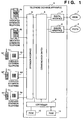
- Fig. 1 is a block diagram showing the construction of a telephone exchange apparatus containing cordless telephones to which the present invention is applied.
- a telephone exchange apparatus 3 is connected to an integrated services digital network (ISDN) 1 via a digital interface 7 and a public switched telephone network (PSTN) 2 such as an analog communication network via an analog interface 8.
- the telephone exchange apparatus 3 accommodates dedicated extension telephones 4a and 4b, and extension cordless telephones consisting of main phones 4c, 4d and 4e and subphones 4c' 4d' and 4e', via an extension interface 5.
- a plural items of audio information from the respective interfaces are exchanged in a communication switch 6, under the control of a controller 9.
- Program for the controller 9 to perform control is stored in a ROM 10, and reading/writing of data necessary for the control is made by using a RAM 11.
- Fig. 2 is a block diagram showing the construction of a main phone of the cordless telephone.
- the main phone is connected to the telephone exchange apparatus 3 via a line 100 and an interface 14. Audio information from the telephone exchange apparatus 3 is transferred to a tuner 12 via an audio interface 13.
- a controller 15 controls the respective circuits of the main phone and transmission of control signals to and from a subphone is done using the tuner 12.
- a program for the controller 15 to perform control of the main phone is stored in a ROM 16, and reading/writing of data necessary for the control is made by using a RAM 17.
- the tuner 12 also has a function of detecting wireless communication signals.
- the tuner 12 includes a MODEM (not shown).
- Fig. 3 is a block diagram showing the construction of the subphone of the cordless telephone.
- the subphone performs wireless communication with the main phone via a tuner 18. Audio information from the main phone is received by a tuner 18 and passed through an audio interface 19, and sent to receiver 20 while audio information inputted from a microphone 21 is transmitted to the main phone through the audio interface 19 and the tuner 18.
- a controller 22 controls audio processing, detection of key input from keys 25, display on an LCD 26 and indication on an LED 27, and also controls transmission of control signals using the tuner 18, to and from the main phone.
- a program for the controller 22 to perform control of the subphone is stored in a ROM 23, and reading/writing of data necessary for the control is made by using a RAM 24.
- the tuner 18 includes a MODEM (not shown).
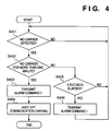
- Fig. 4 is a flowchart showing the operation of the controller 15 of the main phone.
- Fig. 5 is a flowchart showing the operation of the controller 22 of the subphone.
- the flowchart of Fig. 4 shows a carrier detection processing at the main phone when it is in communication.
- the controller 15 of the main phone In communication with the subphone, the controller 15 of the main phone continually monitors carrier signals of the communication channel.
- the controller 15 activates the tuner 12 to transmit an "alarm command 1" to the subphone at five-second intervals (S405 and S406) so as to inform the absence of carrier.
- This alarm command 1 is transmitted by radio waves associated with the communication channel, and received by the subphone.
- the tuner 12 is activated to transmit an "alarm command 2" to the subphone, so as to inform the subphone of shutting off the communication channel (S403). After that, the controller 15 shuts off the wireless communication channel, stops transmission of radio waves, and disconnect the communication between the line 100 and the telephone exchange apparatus 3.
- Fig. 5 is a flowchart showing the processing executed by the subphone in response to the alarm commands which are transmitted from the main phone as shown in Fig. 4.
- the controller 22 of the subphone receives an alarm command 1 from the main phone ("YES” at step S504), the controller 22 displays an "alarm 1" (S505) to be described later.
- the controller 22 receives the alarm command 2 from the main phone ("YES” at step S501), the controller displays an "alarm 2" to be described later, and shuts off the communication channel (S503).
- Figs. 6 to 8 show examples of alarm display at the subphone.
- the subphone emits an alarm 1 which sounds like "[pi]” (1000 Hz, 100 msec) from the audio interface 19 via the receiver 20, as shown in Fig. 6, while displaying a message "OUT OF RANGE” as shown in Fig. 7 on the LCD 26.
- the subphone emits an alarm 2 which sounds like "[pi pi pi]” (2000 Hz, 250 msec) as shown in Fig. 8.
- the transmission intervals of the alarm command 1 are not limited to five seconds, but an appropriate time period may be selected so long as it is shorter than one minute. It should also be noted that duration of the state where no carrier signal is detected is not limited to one minute.
- the audio interface 13 of the main phone and the audio interface 19 of the subphone may incorporate a signal transmission/reception circuit which treats a frequency outside of an audio frequency band (300 Hz to 3400 Hz) of, e.g., an ordinary telephone line, for modulating a signal of the alarm at the frequency out of that band and transmitting the command. Since the transmission of alarm command in this manner affects no influence in the audio frequency band, occurrence of noise due to the transmission of an alarm can be prevented, and only alarm sound can be heard from the subphone.
- an audio frequency band 300 Hz to 3400 Hz
- the main phone itself may transmit the "alarm 1" sounds like "[pi] (1000 Hz, 100 msec) and the “alarm 2" sounds like "[pi pi pi]” (2000 Hz, 250 msec) to the subphone.
- the present invention is applicable to a wireless communication apparatus such as a cordless telephone, which can be directly connected to a public telephone line.
- the main phone when a carrier signal from the subphone has not been detected for a predetermined period, the main phone transmits an alarm command to the subphone, and stops transmission of a wireless signal to the subphone.
- the main phone transmits an alarm command and stops transmission of wireless signal to the subphone. This allows a user, for example, to charge a battery built-in the subphone, in accordance with the alarm command.
- the main phone has the subphone stop transmission of wireless signal, quick termination of communication is possible.
- the present invention can be applied to a system constituted by a plurality of devices or to an apparatus comprising a single device.
Abstract
Description
- This invention relates to a wireless communication apparatus such as a cordless telephone, capable of communication by wireless communication means.
- Conventionally, carrier sensing in cordless telephones is performed independently by a main phone and a subphone. That is, the main phone monitors a carrier signal in radio waves emitted from the subphone, and if it becomes that the carrier signal cannot be detected for a predetermined period, the main phone stops transmission of radio waves. The subphone also detects a carrier signal in radio waves emitted from the main phone, and if it becomes that the carrier signal cannot be detected, the subphone displays an alarm message at predetermined intervals. When the carrier has not been detected for a predetermined period, the subphone stops transmission of radio waves.
- Accordingly, in the above conventional cordless telephone, in a case where output power of radio waves emitted by the subphone becomes low due to, e.g., depletion of a built-in battery, the main phone cannot detect the carrier signal not necessary from the subphone, though the subphone may detect the carrier signal from the main phone. In this case, there is a problem that the main phone may stop transmission of radio waves while any alarm message indicating that no carrier has been detected at the subphone is displayed.
- An object of the present invention is to solve the above problem and provide a wireless communication apparatus which gives an alarm when a subphone cannot detect a carrier signal for a predetermined period, thus avoids abrupt stoppage of radio-wave transmission by a main phone.
- The above object is attained by providing a wireless communication apparatus having a first communication device and a second communication device for mutually performing wireless communication wherein the second communication device comprising:
- detection means for detecting reception of a wireless signal from the first communication device;
- transmission means for transmitting a first alarm signal to the first communication device, if the detection means has not detected reception of the wireless signal; and
- halt means for halting transmission of a wireless signal to the first communication device, after transmission of the first alarm signal by the transmission means.
- Other features and advantages of the present invention will be apparent from the following description taken in conjunction with the accompanying drawings, in which like reference characters designate the same name or similar parts throughout the figures thereon.
- The accompanying drawings, which are incorporated in and constitute a part of the specification, illustrate embodiments of the invention and, together with the description, serve to explain the principles of the invention.
- Fig. 1 is a block diagram showing the construction of a telephone exchange device according to an embodiment of the present invention;
- Fig. 2 is a block diagram showing the construction of a main phone of a cordless telephone apparatus;
- Fig. 3 is a block diagram showing the construction of a subphone of the cordless telephone apparatus;
- Fig. 4 is a flowchart showing the operation of a controller of the main phone of the cordless telephone apparatus;
- Fig. 5 is a flowchart showing the operation of a controller of the subphone of the cordless telephone apparatus;
- Fig. 6 is an example of an
alarm sound 1 according to the embodiment; - Fig. 7 is an example of an
alarm display 1 according to the embodiment; and - Fig. 8 is an example of an
alarm sound 2 according to the embodiment. - Preferred embodiment of the present invention will now described in detail in accordance with the accompanying drawings.
- Fig. 1 is a block diagram showing the construction of a telephone exchange apparatus containing cordless telephones to which the present invention is applied. In Fig. 1, a
telephone exchange apparatus 3 is connected to an integrated services digital network (ISDN) 1 via adigital interface 7 and a public switched telephone network (PSTN) 2 such as an analog communication network via ananalog interface 8. Also, thetelephone exchange apparatus 3 accommodatesdedicated extension telephones main phones subphones 4c' 4d' and 4e', via anextension interface 5. A plural items of audio information from the respective interfaces are exchanged in acommunication switch 6, under the control of a controller 9. Program for the controller 9 to perform control is stored in aROM 10, and reading/writing of data necessary for the control is made by using a RAM 11. - Fig. 2 is a block diagram showing the construction of a main phone of the cordless telephone. The main phone is connected to the
telephone exchange apparatus 3 via aline 100 and aninterface 14. Audio information from thetelephone exchange apparatus 3 is transferred to atuner 12 via anaudio interface 13. Acontroller 15 controls the respective circuits of the main phone and transmission of control signals to and from a subphone is done using thetuner 12. A program for thecontroller 15 to perform control of the main phone is stored in aROM 16, and reading/writing of data necessary for the control is made by using aRAM 17. Thetuner 12 also has a function of detecting wireless communication signals. Thetuner 12 includes a MODEM (not shown). - Fig. 3 is a block diagram showing the construction of the subphone of the cordless telephone. The subphone performs wireless communication with the main phone via a
tuner 18. Audio information from the main phone is received by atuner 18 and passed through anaudio interface 19, and sent toreceiver 20 while audio information inputted from amicrophone 21 is transmitted to the main phone through theaudio interface 19 and thetuner 18. - A
controller 22 controls audio processing, detection of key input fromkeys 25, display on anLCD 26 and indication on anLED 27, and also controls transmission of control signals using thetuner 18, to and from the main phone. A program for thecontroller 22 to perform control of the subphone is stored in aROM 23, and reading/writing of data necessary for the control is made by using aRAM 24. Thetuner 18 includes a MODEM (not shown). - Fig. 4 is a flowchart showing the operation of the
controller 15 of the main phone. Fig. 5 is a flowchart showing the operation of thecontroller 22 of the subphone. The flowchart of Fig. 4 shows a carrier detection processing at the main phone when it is in communication. In communication with the subphone, thecontroller 15 of the main phone continually monitors carrier signals of the communication channel. In a case where a carrier signal from the subphone is not detected by the tuner 12 ("YES" at step S401) and a state where no carrier signal is detected continues for less than one minute ("NO" at step S402), thecontroller 15 activates thetuner 12 to transmit an "alarm command 1" to the subphone at five-second intervals (S405 and S406) so as to inform the absence of carrier. Thisalarm command 1 is transmitted by radio waves associated with the communication channel, and received by the subphone. If thecontroller 15 has not detected the carrier signal for more than one minute ("YES" at step S402), thetuner 12 is activated to transmit an "alarm command 2" to the subphone, so as to inform the subphone of shutting off the communication channel (S403). After that, thecontroller 15 shuts off the wireless communication channel, stops transmission of radio waves, and disconnect the communication between theline 100 and thetelephone exchange apparatus 3. - Fig. 5 is a flowchart showing the processing executed by the subphone in response to the alarm commands which are transmitted from the main phone as shown in Fig. 4. When the
controller 22 of the subphone receives analarm command 1 from the main phone ("YES" at step S504), thecontroller 22 displays an "alarm 1" (S505) to be described later. When thecontroller 22 receives thealarm command 2 from the main phone ("YES" at step S501), the controller displays an "alarm 2" to be described later, and shuts off the communication channel (S503). - Figs. 6 to 8 show examples of alarm display at the subphone. The subphone emits an
alarm 1 which sounds like "[pi]" (1000 Hz, 100 msec) from theaudio interface 19 via thereceiver 20, as shown in Fig. 6, while displaying a message "OUT OF RANGE" as shown in Fig. 7 on theLCD 26. Similarly, the subphone emits analarm 2 which sounds like "[pi pi pi]" (2000 Hz, 250 msec) as shown in Fig. 8. - It should be noted that the transmission intervals of the
alarm command 1 are not limited to five seconds, but an appropriate time period may be selected so long as it is shorter than one minute. It should also be noted that duration of the state where no carrier signal is detected is not limited to one minute. - Further, the
audio interface 13 of the main phone and theaudio interface 19 of the subphone may incorporate a signal transmission/reception circuit which treats a frequency outside of an audio frequency band (300 Hz to 3400 Hz) of, e.g., an ordinary telephone line, for modulating a signal of the alarm at the frequency out of that band and transmitting the command. Since the transmission of alarm command in this manner affects no influence in the audio frequency band, occurrence of noise due to the transmission of an alarm can be prevented, and only alarm sound can be heard from the subphone. - Further, the main phone itself may transmit the "
alarm 1" sounds like "[pi] (1000 Hz, 100 msec) and the "alarm 2" sounds like "[pi pi pi]" (2000 Hz, 250 msec) to the subphone. - The present invention is applicable to a wireless communication apparatus such as a cordless telephone, which can be directly connected to a public telephone line.
- As described above, according to the present invention, when a carrier signal from the subphone has not been detected for a predetermined period, the main phone transmits an alarm command to the subphone, and stops transmission of a wireless signal to the subphone. By adopting this configuration, it is possible to avoid abrupt shut-off of radio waves from the main phone to the subphone.
- Further, when a wireless signal has not been received for a predetermined period, the main phone transmits an alarm command and stops transmission of wireless signal to the subphone. This allows a user, for example, to charge a battery built-in the subphone, in accordance with the alarm command.
- Furthermore, repetition of transmission of the alarm command, or change of display in accordance with the degree of alarm indicated by the alarm command makes notification of the alarm exactly.
- In addition, as the main phone has the subphone stop transmission of wireless signal, quick termination of communication is possible.
- Further, while in communication, by transmitting an alarm using a signal at a frequency outside of an audio frequency band (300 Hz to 3400 Hz), a certain noise which is audible in communication can be eliminated.
- The present invention can be applied to a system constituted by a plurality of devices or to an apparatus comprising a single device.
- As many apparently widely different embodiments of the present invention can be made without departing from the spirit and scope thereof, it is to be understood that the invention is not limited to the specific embodiments thereof except as defined in the appended claims.
Claims (26)
- A wireless communication apparatus having a first communication device (4c', 4d', 4e') and a second communication device (4c, 4d, 4e) for mutually performing wireless communication, wherein said second communication device comprising:detection means (12, 15) for detecting reception of a wireless signal from said first communication device;transmission means (12, 13, 15) for transmitting a first alarm signal to said first communication device, if said detection means has not detected reception of the wireless signal; andhalt means (15) for halting transmission of a wireless signal to said first communication device, after transmission of the first alarm signal by said transmission means.
- The wireless communication apparatus according to Claim 1, wherein if a state in which no reception of the wireless signal has continued for a predetermined period, said halt means halts the transmission of the wireless signal to said first communication device.
- The wireless communication apparatus according to Claim 1, wherein said transmission means repeatedly transmits the first alarm signal at predetermined intervals before said halt means halts the transmission of the wireless signal.
- The wireless communication apparatus according to Claim 1, wherein said transmission means transmits a second alarm signal when said halt means halts the transmission of the wireless signal.
- The wireless communication apparatus according to Claim 1, wherein the first alarm signal is a command to said first communication device to perform a predetermined display.
- The wireless communication apparatus according to Claim 5, wherein said first communication device, upon reception of the command for performing the predetermined display, performs a visible display, an audible indication or a display obtained by the combination of the visible display and the audible indication.
- The wireless communication apparatus according to Claim 4, wherein the first and second alarm signals are display commands instructing to perform display operations different from each other.
- The wireless communication apparatus according to Claim 4, wherein, upon reception of the second alarm signal, said first communication device halts transmission of the wireless signal to said second communication device.
- The wireless communication apparatus according to Claim 4, wherein said transmission means transmits the first and second alarm signals by utilizing a frequency outside of an audible frequency band.
- The wireless communication apparatus according to Claim 4, further comprising control (15) means for performing a control such that the wireless communication between said first and second communication devices is terminated after said transmission means transmits the second alarm signal.
- The wireless communication apparatus according to Claim 1, wherein said first communication device is a portable device, while said second communication device is a stationary device.
- The wireless communication apparatus according to Claim 10, further comprising connection means (5, 6, 7, 8, 9, 14) for connecting a wireless communication circuit between said first and second communication devices to an external communication line (1, 2, 100) accommodated by said wireless communication apparatus,wherein after said transmission means transmits the second alarm signal, said control means disconnects the connection between the wireless communication circuit and the external communication line and terminates the wireless communication.
- The wireless communication apparatus according to Claim 1, wherein the first alarm signal includes a sound signal.
- A communication control method comprising the steps of:detecting a signal from a communication terminal;transmitting a first alarm signal to the communication terminal if no signal has been detected at said detecting step; andhalting transmission to the communication terminal after transmission of the first alarm signal.
- The communication control method according to Claim 14, wherein, if a state where no reception of the signal has continued for a predetermined period, transmission to the communication terminal is halted.
- The communication control method according to Claim 14, wherein the first alarm signal is transmitted at predetermined intervals before the transmission to the communication terminal is halted.
- The communication control method according to Claim 14, wherein a second alarm signal is transmitted when the transmission to the communication terminal is halted.
- The communication control method according to Claim 14, wherein the first alarm signal is a command to the communication terminal to perform a predetermined display.
- The communication control method according to Claim 18, wherein the communication terminal, upon reception of the command for performing the predetermined display, performs a visible display, an audible indication or a display obtained by the combination of the visible display and the audible indication.
- The communication control method according to Claim 17, wherein the first and second alarm signals are display commands instructing to perform display operations different from each other.
- The communication control method according to Claim 17, wherein the communication terminal halts the transmission upon reception of the second alarm signal.
- The communication control method according to Claim 17, wherein the first and second alarm signals are transmitted by utilizing a frequency outside of an audio frequency band.
- The communication control method according to Claim 17, further comprising a step of performing a control such that communication is terminated after the second alarm signal is transmitted.
- The communication control method according to Claim 14, wherein the communication terminal is a portable device.
- The communication control method according to Claim 23, wherein connection is made between the communication terminal and an external communication line, and the communication terminal terminates the communication by disconnecting the connection after the second alarm signal is transmitted.
- The communication control method according to Claim 14, wherein the first alarm signal includes a sound signal.
Applications Claiming Priority (3)
| Application Number | Priority Date | Filing Date | Title |
|---|---|---|---|
| JP28540194 | 1994-11-18 | ||
| JP6285401A JPH08149559A (en) | 1994-11-18 | 1994-11-18 | Radio communication equipment |
| JP285401/94 | 1994-11-18 |
Publications (3)
| Publication Number | Publication Date |
|---|---|
| EP0713316A2 true EP0713316A2 (en) | 1996-05-22 |
| EP0713316A3 EP0713316A3 (en) | 1996-12-18 |
| EP0713316B1 EP0713316B1 (en) | 2004-02-11 |
Family
ID=17691056
Family Applications (1)
| Application Number | Title | Priority Date | Filing Date |
|---|---|---|---|
| EP95402587A Expired - Lifetime EP0713316B1 (en) | 1994-11-18 | 1995-11-17 | Wireless communication apparatus |
Country Status (5)
| Country | Link |
|---|---|
| US (1) | US5999809A (en) |
| EP (1) | EP0713316B1 (en) |
| JP (1) | JPH08149559A (en) |
| CN (1) | CN1043117C (en) |
| DE (1) | DE69532550T2 (en) |
Cited By (3)
| Publication number | Priority date | Publication date | Assignee | Title |
|---|---|---|---|---|
| WO2002078302A2 (en) * | 2001-03-22 | 2002-10-03 | Siemens Aktiengesellschaft | Headset system |
| DE10250221A1 (en) * | 2002-10-23 | 2004-05-06 | Deutsche Telekom Ag | Signaling interruption in communication between mobile telecommunication devices, by generating acoustic, visual or mechanical warning to user in event of interruption or fault |
| CN105223822A (en) * | 2015-09-24 | 2016-01-06 | 广东欧珀移动通信有限公司 | Resource provision facility switching control method and device |
Families Citing this family (7)
| Publication number | Priority date | Publication date | Assignee | Title |
|---|---|---|---|---|
| IL132888A0 (en) | 1999-11-11 | 2001-03-19 | Surf Comm Solutions Ltd | Channel load balancing |
| JP2001094497A (en) * | 1999-09-17 | 2001-04-06 | Nec Corp | Wireless phone and method for informing the wireless phone about its residence on outside of zone |
| US7257642B1 (en) | 1999-11-11 | 2007-08-14 | Surp Communication Solutions Ltd. | Channel load balancing |
| WO2001086466A2 (en) * | 2000-05-09 | 2001-11-15 | Surf Communication Solutions, Ltd. | Always-on access server pool |
| DE60144510D1 (en) | 2000-12-27 | 2011-06-09 | Canon Kk | Wireless communication system with control of transmission timing |
| JP3843768B2 (en) * | 2001-06-22 | 2006-11-08 | ソニー株式会社 | Call control method, call control system, and radio telephone apparatus |
| CN104964455A (en) * | 2015-07-21 | 2015-10-07 | 庄景阳 | Water heater protection device achieving switch wireless induction outage |
Family Cites Families (21)
| Publication number | Priority date | Publication date | Assignee | Title |
|---|---|---|---|---|
| JPS5475201A (en) * | 1977-11-28 | 1979-06-15 | Nec Corp | Radiotelephony unit |
| JPS54124602A (en) * | 1978-03-20 | 1979-09-27 | Nec Corp | Radiotelephony system |
| JPS6027218B2 (en) * | 1980-10-31 | 1985-06-27 | 日本電気株式会社 | Control channel failure detection method for wireless telephone equipment |
| JPS60170341A (en) * | 1984-02-14 | 1985-09-03 | Nec Corp | Exchange system |
| US5245314A (en) * | 1985-09-18 | 1993-09-14 | Kah Jr Carl L C | Location monitoring system |
| JPH0734598B2 (en) * | 1986-07-24 | 1995-04-12 | ソニー株式会社 | Cordless telephone |
| DE3643004A1 (en) * | 1986-12-17 | 1988-06-30 | Philips Patentverwaltung | METHOD AND CIRCUIT FOR CONNECTING AND MONITORING A CORDLESS TELEPHONE APPARATUS |
| JP2601833B2 (en) * | 1987-08-24 | 1997-04-16 | 日本電信電話株式会社 | Cordless telephone equipment |
| JPS6486724A (en) * | 1987-09-29 | 1989-03-31 | Toshiba Corp | Radio telephone system |
| JPH0276423A (en) * | 1988-09-13 | 1990-03-15 | Fujitsu Ltd | Cordless telephone communication system |
| JPH02184149A (en) * | 1989-01-11 | 1990-07-18 | Iwatsu Electric Co Ltd | Cordless telephone system |
| US5373548A (en) * | 1991-01-04 | 1994-12-13 | Thomson Consumer Electronics, Inc. | Out-of-range warning system for cordless telephone |
| JPH04264855A (en) * | 1991-02-19 | 1992-09-21 | Toshiba Corp | Cordless telephone set |
| TW327488U (en) * | 1991-05-29 | 1998-02-21 | Video Tech Eng | Digital cordless telephone apparatus |
| JP2652825B2 (en) * | 1991-08-05 | 1997-09-10 | 株式会社田村電機製作所 | Cordless telephone |
| JPH05219154A (en) * | 1992-01-31 | 1993-08-27 | Meisei Electric Co Ltd | Out-of calling range informing circuit for cordless telephone system |
| US5425076A (en) * | 1992-06-30 | 1995-06-13 | Minnesota Mining And Manufacturing Company | Cellular communications test system |
| JP3120387B2 (en) * | 1992-08-04 | 2000-12-25 | ユニデン株式会社 | Cordless telephone equipment |
| US5451839A (en) * | 1993-01-12 | 1995-09-19 | Rappaport; Theodore S. | Portable real time cellular telephone and pager network system monitor |
| US5581599A (en) * | 1993-12-30 | 1996-12-03 | Northern Telecom Limited | Cordless telephone terminal |
| US5490288A (en) * | 1994-02-08 | 1996-02-06 | Motorola, Inc. | Method for determining low signal quality communications |
-
1994
- 1994-11-18 JP JP6285401A patent/JPH08149559A/en active Pending
-
1995
- 1995-11-15 US US08/559,285 patent/US5999809A/en not_active Expired - Lifetime
- 1995-11-17 EP EP95402587A patent/EP0713316B1/en not_active Expired - Lifetime
- 1995-11-17 DE DE69532550T patent/DE69532550T2/en not_active Expired - Lifetime
- 1995-11-17 CN CN95119725A patent/CN1043117C/en not_active Expired - Fee Related
Non-Patent Citations (1)
| Title |
|---|
| None |
Cited By (5)
| Publication number | Priority date | Publication date | Assignee | Title |
|---|---|---|---|---|
| WO2002078302A2 (en) * | 2001-03-22 | 2002-10-03 | Siemens Aktiengesellschaft | Headset system |
| WO2002078302A3 (en) * | 2001-03-22 | 2002-11-21 | Siemens Ag | Headset system |
| US7251498B2 (en) | 2001-03-22 | 2007-07-31 | Siemens Aktiengesellschaft | Radio headset system |
| DE10250221A1 (en) * | 2002-10-23 | 2004-05-06 | Deutsche Telekom Ag | Signaling interruption in communication between mobile telecommunication devices, by generating acoustic, visual or mechanical warning to user in event of interruption or fault |
| CN105223822A (en) * | 2015-09-24 | 2016-01-06 | 广东欧珀移动通信有限公司 | Resource provision facility switching control method and device |
Also Published As
| Publication number | Publication date |
|---|---|
| US5999809A (en) | 1999-12-07 |
| EP0713316B1 (en) | 2004-02-11 |
| JPH08149559A (en) | 1996-06-07 |
| CN1043117C (en) | 1999-04-21 |
| EP0713316A3 (en) | 1996-12-18 |
| DE69532550T2 (en) | 2004-12-16 |
| CN1132989A (en) | 1996-10-09 |
| DE69532550D1 (en) | 2004-03-18 |
Similar Documents
| Publication | Publication Date | Title |
|---|---|---|
| US5867796A (en) | Portable telephone set capable of being put in a holding mode by operation of a vibration unit which is for announcing reception of an incoming call to a user | |
| US5999809A (en) | Wireless communication apparatus with distinct alarm signals | |
| KR910007709B1 (en) | Radio telephone device | |
| JPH0555996A (en) | Cordless telephone set | |
| JP2806702B2 (en) | Digital cordless button telephone device | |
| JP2752994B2 (en) | Wireless telephone equipment | |
| US6002938A (en) | Mobile telephone which inhibits an operation of an indication for a calling telephone requesting communication | |
| US6799060B1 (en) | Apparatus and method for providing dialing announcement in a telephone terminal | |
| JP2653005B2 (en) | Wireless telephone | |
| AU682163B2 (en) | Call management in a telecommunication system | |
| KR960003104B1 (en) | Wireless calling devices for keyphone system | |
| JP2000196713A (en) | Method for notifying incoming call for telephone set | |
| KR20030070030A (en) | Methods and apparatus for communicating information from a remote wireless device to a cordless telephone system | |
| KR0175587B1 (en) | Wireless telephone capable of displaying current time on a portable device and control method thereof | |
| JP3223104B2 (en) | Wireless telephone device and cordless telephone device | |
| JP3223148B2 (en) | Cordless telephone equipment | |
| KR0148466B1 (en) | Method for making communication link using speakerphone of fixing apparatus in a wireless telephone0 | |
| JPH0585142U (en) | Wireless phone | |
| JPH10257560A (en) | Radio communication equipment | |
| JP2899444B2 (en) | Wireless telephone equipment | |
| JPH03108848A (en) | Cordless telephone set | |
| KR20000039245A (en) | Method for implementing short rest function in cellular phone | |
| JPH05236551A (en) | Ha system | |
| KR20010088996A (en) | Apparatus and method for remote monitor using codeless telephone within cid | |
| KR19980046093A (en) | Extension Call between Mobile Devices in Wireless Telephones |
Legal Events
| Date | Code | Title | Description |
|---|---|---|---|
| PUAI | Public reference made under article 153(3) epc to a published international application that has entered the european phase |
Free format text: ORIGINAL CODE: 0009012 |
|
| AK | Designated contracting states |
Kind code of ref document: A2 Designated state(s): DE FR GB |
|
| PUAL | Search report despatched |
Free format text: ORIGINAL CODE: 0009013 |
|
| AK | Designated contracting states |
Kind code of ref document: A3 Designated state(s): DE FR GB |
|
| 17P | Request for examination filed |
Effective date: 19970510 |
|
| 17Q | First examination report despatched |
Effective date: 20010813 |
|
| GRAP | Despatch of communication of intention to grant a patent |
Free format text: ORIGINAL CODE: EPIDOSNIGR1 |
|
| GRAS | Grant fee paid |
Free format text: ORIGINAL CODE: EPIDOSNIGR3 |
|
| GRAA | (expected) grant |
Free format text: ORIGINAL CODE: 0009210 |
|
| AK | Designated contracting states |
Kind code of ref document: B1 Designated state(s): DE FR GB |
|
| REG | Reference to a national code |
Ref country code: GB Ref legal event code: FG4D |
|
| REF | Corresponds to: |
Ref document number: 69532550 Country of ref document: DE Date of ref document: 20040318 Kind code of ref document: P |
|
| ET | Fr: translation filed | ||
| PLBE | No opposition filed within time limit |
Free format text: ORIGINAL CODE: 0009261 |
|
| STAA | Information on the status of an ep patent application or granted ep patent |
Free format text: STATUS: NO OPPOSITION FILED WITHIN TIME LIMIT |
|
| 26N | No opposition filed |
Effective date: 20041112 |
|
| PGFP | Annual fee paid to national office [announced via postgrant information from national office to epo] |
Ref country code: FR Payment date: 20081124 Year of fee payment: 14 |
|
| REG | Reference to a national code |
Ref country code: FR Ref legal event code: ST Effective date: 20100730 |
|
| PG25 | Lapsed in a contracting state [announced via postgrant information from national office to epo] |
Ref country code: FR Free format text: LAPSE BECAUSE OF NON-PAYMENT OF DUE FEES Effective date: 20091130 |
|
| PGFP | Annual fee paid to national office [announced via postgrant information from national office to epo] |
Ref country code: DE Payment date: 20131130 Year of fee payment: 19 Ref country code: GB Payment date: 20131119 Year of fee payment: 19 |
|
| REG | Reference to a national code |
Ref country code: DE Ref legal event code: R119 Ref document number: 69532550 Country of ref document: DE |
|
| GBPC | Gb: european patent ceased through non-payment of renewal fee |
Effective date: 20141117 |
|
| PG25 | Lapsed in a contracting state [announced via postgrant information from national office to epo] |
Ref country code: DE Free format text: LAPSE BECAUSE OF NON-PAYMENT OF DUE FEES Effective date: 20150602 Ref country code: GB Free format text: LAPSE BECAUSE OF NON-PAYMENT OF DUE FEES Effective date: 20141117 |