EP0715437A1 - Routing method for ATM network - Google Patents
Routing method for ATM network Download PDFInfo
- Publication number
- EP0715437A1 EP0715437A1 EP95402660A EP95402660A EP0715437A1 EP 0715437 A1 EP0715437 A1 EP 0715437A1 EP 95402660 A EP95402660 A EP 95402660A EP 95402660 A EP95402660 A EP 95402660A EP 0715437 A1 EP0715437 A1 EP 0715437A1
- Authority
- EP
- European Patent Office
- Prior art keywords
- switches
- cells
- input
- sub
- output
- Prior art date
- Legal status (The legal status is an assumption and is not a legal conclusion. Google has not performed a legal analysis and makes no representation as to the accuracy of the status listed.)
- Withdrawn
Links
Images


Classifications
-
- H—ELECTRICITY
- H04—ELECTRIC COMMUNICATION TECHNIQUE
- H04L—TRANSMISSION OF DIGITAL INFORMATION, e.g. TELEGRAPHIC COMMUNICATION
- H04L45/00—Routing or path finding of packets in data switching networks
- H04L45/24—Multipath
-
- H—ELECTRICITY
- H04—ELECTRIC COMMUNICATION TECHNIQUE
- H04L—TRANSMISSION OF DIGITAL INFORMATION, e.g. TELEGRAPHIC COMMUNICATION
- H04L45/00—Routing or path finding of packets in data switching networks
- H04L45/02—Topology update or discovery
- H04L45/10—Routing in connection-oriented networks, e.g. X.25 or ATM
Definitions
- the field of the invention is that of switching networks with asynchronous time division multiplexing, such as, in particular, networks supporting ATM cell traffic (Asynchronous Transfer Mode in English).
- the invention relates to the routing (or routing) of cells in such a switching network with asynchronous time division multiplexing.
- a switching network makes it possible to interconnect input switches and output switches by means of switches.
- a sequence of cells belonging to a given communication must be able to be transmitted between any of the input switches and any of the output switches.
- each of the input switches can be connected to each of the output switches by at least two separate paths, each path corresponding to a distinct series of switches.
- Each switch includes at least two inputs and at least two outputs, and is designed to transfer to one of its outputs a cell received on one of its inputs.
- a first known mode of routing consists in defining a single path for the series of cells to be transmitted belonging to a given communication. Thus, after a communication establishment phase (during which the path is determined), all the cells pass successively through this single path.
- This first known mode of routing has the advantage of requiring the search (and then the use) of only one path. However, finding that one path can be problematic. In fact, it may be that during the communication establishment phase, no path can be found when the switching network is not saturated.
- This situation called blocking in the broad sense, therefore corresponds to the case where, although an input switch and an output switch are available, the routing mode chosen is such that there is no series of switches allowing them to be interconnected. It should be noted that a blocking situation in the strict sense corresponds to the case where there is no possible path between an input switch and an output switch, regardless of the routing mode chosen.
- a known solution consists in carrying out a spatial expansion (increase in the number of switches in the network and / or an increase in speed), which increases the cost and the complexity of the network.
- Another known solution consists in rearranging the paths associated with the communications already established, so as to make certain switches available and allow the development of a path. Such a rearrangement of the paths is a complex operation, or even impossible if there are several simultaneous blockings.
- a second known mode of routing consists in transmitting in a decorrelated manner the cells of the same sequence belonging to a given communication.
- the successive cells of the same sequence take different paths (we also speak of multi-path mode).
- the assignment of a path to a cell is generally carried out according to a random distribution.
- the number of different paths is arbitrary, and generally limited to the minimum number necessary.
- multi-path networks In order to avoid bottlenecks, so-called multi-path networks generally include a cell mixing stage. Unfortunately, such a patching stage does not make it possible to control the differences in flow rates arriving on the various input switches.
- the invention particularly aims to overcome these various drawbacks of the state of the art.
- one of the objectives of the present invention is to provide a method of routing cells in an asynchronous time-division multiplex switching network, which offers a non-blocking situation in the broad sense of the network without requiring spatial expansion. (increase in the number of matrices) or expansion of the network speed until it is saturated.
- an objective of the invention is to avoid clogging of the buffer memories of the switches.
- Another objective of the invention is to provide such a routing method which does not require the complex implementation of a random distribution of the cells on different paths.
- the routing method of the invention consists, for each series of cells to be transmitted, to determine all the possible paths, to establish a sub-connection for each of the possible paths, and to systematically and in turn assign role one of the sub-connections to each cell.
- each of the N sub-connections originating from an input switch for a given communication supports 1 / N of the traffic arriving on this input switch.
- said distribution is cyclical.
- the distribution of the invention ensures an equitable distribution of traffic on the network, which limits the risks of clogging of the buffers of the switches, and allows the non-blocking (in the broad sense) of the network.
- each of said input switches is associated with a switch belonging to a first stage
- each of said output switches is associated with a switch belonging to a last stage
- the switches of said first and last stages being interconnected by means of at least two switches forming at least one intermediate stage, the number of possible paths corresponding to the number of switches assigned to cell transfer and belonging to said intermediate stage or to the product of numbers of switches assigned to cell transfer and belonging to each of said intermediate stages.
- the central floor constitutes the only floor intermediate.
- the routing method of the invention makes it possible to halve, compared to the solution without blocking in the strict sense, the number of switches per access.
- each of said switches is duplicated, so as to ensure in parallel a double transmission of each of said cells.
- the cells received in parallel are compared.
- the network is duplicated in two branches (or planes), each branch being a switching network with asynchronous time division multiplexing, which provides good tolerance for failures or transmission errors.
- each of said cells is assigned error detection and / or correction data, and, on reception, the quality of the cells received is checked in parallel, and those with the best quality are selected to reconstruct said sequence. .
- the network is thus able to withstand multiple errors or failures, until a matrix in one branch and its duplicate in the other branch are simultaneously down.
- the location of a faulty matrix in a branch is facilitated by knowing the path taken by a disturbed cell having crossed this faulty matrix.
- each of said input switches also comprises a modulo N counter, incremented for each new cell to be transmitted from said cell, said allocation means assigning one of said sub-connections to each cell of said sequence according to the value entered in said counter.
- the invention also relates to the input switch as such of a network of the type described above, as well as the applications of the method presented above.
- the invention therefore relates to a method for routing cells in an asynchronous time division multiplex switching network.
- asynchronous transfer mode (ATM, for Asynchronous Transfer Mode in English)
- the cells which constitute the data units, have a fixed and short structure and follow each other without absolute position reference.
- the identification of the communication channel is indeed carried by the cell itself, in a header. Consequently, a source can emit cells at its own rate, without direct reference to the communication network to which it is connected.
- FIG. 1 schematically presents an example of a switching network in which the cell routing method of the invention can be implemented.
- This network interconnects input ports ME1 to ME4 and output ports MS1 to MS4 via intermediate switches M1 to M8. Subsequently, it is considered that said ports are switches, or matrices.
- Each associated input switch ME1 to ME4 can be connected to each of the associated output switches MS1 to MS4 by at least two paths, each path corresponding to a distinct series of switches M1 to M8.
- a series of switches defining a path is in fact made up of a single switch M1 to M8.
- Each intermediate switch M1 to M8 comprises at least two inputs and at least two outputs and is designed to transfer to one of its outputs a cell received on one of its inputs.
- the network mesh has not been represented, that is to say all the permanent links existing on the one hand between the outputs of the input switches ME1 and ME4 and the inputs of intermediate switches M1 to M8, and on the other hand between the outputs of intermediate switches M1 to M8 and the inputs of output switches MS1 to MS4.
- a sub-connection is a virtual conduit to which certain cells of the same communication are directed, according to a systematic and cyclical distribution.
- a sub-connection is generally only defined for the duration of this communication.
- FIG. 1 we consider by way of example the case where it is desired to transmit a series of cells between the input switch ME1 and the output switch MS3.
- the census step makes it possible to establish 8 possible paths between ME1 and MS3, each path corresponding to the passage by one of the eight intermediate switches M1 to M8.
- the next step is to establish 8 sub-connections SC0 to SC7 corresponding to the 8 possible paths.
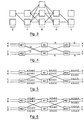
- the step of distributing the cells to the sub-connections is illustrated in FIG. 2.
- the first sub-connection SC0 receives cells C1 and C9; the second sub-connection SC1 receives cells C2 and C10; the third sub-connection SC2 receives cells C3 and C11; etc ...
- each sub-connection receives all the cells which, modulo N, have the same serial number in the following, with N the total number of established sub-connections.
- each input switch ME1 to ME4 is associated with a switch belonging to a first stage
- each output switch is associated with a switch belonging to a last stage
- these switches of the first and last stages are interconnected by means of at least two switches forming at least one intermediate stage.
- the number N of possible paths between an input switch and an output switch is a function of the number of switches belonging to the intermediate stage or stages and which are assigned to the cell transfer.
- N k
- Each input switch ME1, ME2 has two inputs A, B and C, D respectively and two outputs. Each of the two outputs of an input switch ME1, ME2 is connected to an input of each of the two switches M1, M2. Each of the two outputs of a switch M1, M2 is connected to an input of each of the two output switches MS1, MS2. Each output switch MS 1, MS2 has two outputs X, Y and Z, T respectively.
- this blocking situation is avoided. Indeed, for each communication arriving on an input A, B, C, D of input switch ME1, ME2, as many sub-connections are established as there are switches M1, M2 in the single intermediate stage (i.e. two sub-connections in this example).
- the flow arriving on each input A, B, C, D is distributed over several (two in this example) sub-connections, the cells arriving on an input being distributed systematically and cyclically to the different sub-connections corresponding to the different paths.
- each sub-connection carries half of the initial speed and the same link can therefore support two sub-connections allowing the transmission of cells belonging to two separate communications.
- the link between the input switch ME1 and the switch M1 supports a sub-connection connecting the input A to the output T and a sub-connection connecting the input B to the output Y.
- each of the switches is duplicated and the network consists of two identical branches (or planes) 81, 82.
- Each cell to be transmitted 83 is also duplicated (84), the two cells obtained 85, 86 being transmitted in parallel in the two planes 81, 82.
- a cell 810 is selected (after comparison) (89) from two cells received 87, 88.
- each cell to be transmitted 83 an error detection and / or correction data item (CRC byte for example).
- CRC byte for example
- the most probable cell 810 is selected (89) as a function of the error detection and / or correction data.
- the network input switches perform a cellulization function and the network output switches a decellulization.
- the network input switches receive byte frames and the network output switches also generate byte frames.
- the input switches make it possible to pass from a synchronous transmission mode to an asynchronous transmission mode, the output switches allowing the reverse passage.
- FIG. 9 presents a diagram of a particular embodiment of a network input switch 91 according to the invention, of the type receiving data frames on input links 92 1 to 92 3 and generating cells data on output links 93 1 to 93 2 .
- the input links 92 1 , 92 2 are for example synchronous links at 155.52 Mbit / s carrying frames of the STM1 type.
- the output links 93 1 , 93 2 are for example asynchronous links at 622 Mbit / s each corresponding to an access to one of the two branches of an ATM network, as will be explained below.
- Each input link 92 1 , 92 2 and each output link 93 1 , 93 2 corresponds to line end equipment 94 1 , 94 2 , 95 1 , 95 2 .
- the STM1 frames received on the input links 94 , 92 2 are transformed into data cells in a cellulizer 96 (presented below in connection with FIG. 10).
- a cellulizer 96 presents below in connection with FIG. 10.
- Each cell emitted by the cellulizer 96 is duplicated in a duplication module 97 (QRP component operating in IEM mode for example) and the two cells obtained are each directed to one of the two output links 93 1 , 93 2 .
- the routing method implemented in this particular embodiment of the invention is therefore of the type presented previously in relation to FIG. 8. for each sequence of cells generated by the cellulizer, two identical sequences of cells will be transmitted in two parallel network plans which each constitute an asynchronous time division multiplex switching network implementing the routing method of the invention with in particular the establishment of N sub-connections corresponding to the N possible paths, and the systematic and cyclic distribution cells to the N sub-connections).
- FIG. 10 presents a diagram of a particular embodiment of the cellulizer 96 included in the input switch 91 of FIG. 9.
- a cellulizer 96 is associated with each input link 92 1 , 92 2. This cellulizer receives, after synchronization of the incoming frames, a succession of bytes 101.
- Two registers 102, 103 successively receive each byte and its corresponding number in the frame.
- this buffer register 106 When this buffer register 106 is full, it is copied into the data field 104 of a cell 105.
- the C1 bytes intended for the same cell also make it possible to calculate a CRC data item for detection and / or correction of errors.
- This CRC data is stored in a buffer register 108, then written, with the frame number, in a buffer register 109 AAL (ATM adaptation layer).
- this buffer register 109 being copied into an AAL field 1010 of each cell 105.
- each group x there are d different sub-connections under which are successively and cyclically distributed the successive cells of the same sequence (for example associated with a given communication).
- FIG. 11 presents a diagram of an embodiment of a network output switch 110 according to the invention, of the type generating data frames on output links 112 1 , 112 2 from sequences of cells of data received from links input 111 1 , 111 2 .
- the output switch 112 1 , 112 2 is for example a synchronous link at 155.52 Mbit / s carrying frames of the STM1 type.
- Each cell 113 received on an input link 111 1 is temporarily stored in a buffer register. Depending on the ICI and the frame number, the useful data field and the CRC are written in the degig memory 114 associated with this input link 111 1 .
- the useful data field and the CRC of the corresponding cell received on the other input link 111 2 are stored in the clearing memory associated with this other input link 111 2 .
- the de-icing is carried out in each memory by reserving a place per cell expected. In this way, resequencing is automatically ensured, and the detection of missing cells is immediate.
Abstract
Description
Le domaine de l'invention est celui des réseaux de commutation à multiplexage temporel asynchrone, tels que, notamment, les réseaux supportant un trafic de cellules ATM (Asynchronous Transfer Mode en anglo-saxon).The field of the invention is that of switching networks with asynchronous time division multiplexing, such as, in particular, networks supporting ATM cell traffic (Asynchronous Transfer Mode in English).
Plus précisément, l'invention concerne l'acheminement (ou routage) des cellules dans un tel réseau de commutation à multiplexage temporel asynchrone.More specifically, the invention relates to the routing (or routing) of cells in such a switching network with asynchronous time division multiplexing.
D'une façon générale, un réseau de commutation permet d'interconnecter des commutateurs d'entrée et des commutateurs de sortie par l'intermédiaire de commutateurs. Une suite de cellules appartenant à une communication donnée doit pouvoir être transmise entre l'un quelconque des commutateurs d'entrée et l'un quelconque des commutateurs de sortie.Generally speaking, a switching network makes it possible to interconnect input switches and output switches by means of switches. A sequence of cells belonging to a given communication must be able to be transmitted between any of the input switches and any of the output switches.
En général, dans un tel réseau, chacun des commutateurs d'entrée peut être relié à chacun des commutateurs de sortie par au moins deux chemins distincts, chaque chemin correspondant à une suite distincte de commutateurs. Chaque commutateur comprend au moins deux entrées et au moins deux sorties, et est prévu pour transférer sur une de ses sorties une cellule reçue sur une de ses entrées.In general, in such a network, each of the input switches can be connected to each of the output switches by at least two separate paths, each path corresponding to a distinct series of switches. Each switch includes at least two inputs and at least two outputs, and is designed to transfer to one of its outputs a cell received on one of its inputs.
On connaît principalement deux modes d'acheminement de cellules dans un réseau de commutation à multiplexage temporel asynchrone.There are mainly two known modes of cell routing in an asynchronous time division multiplex switching network.
Un premier mode connu d'acheminement consiste à définir un unique chemin pour la suite des cellules à transmettre appartenant à une communication donnée. Ainsi, après une phase d'établissement de la communication (lors de laquelle est déterminé le chemin), toutes les cellules passent successivement par cet unique chemin.A first known mode of routing consists in defining a single path for the series of cells to be transmitted belonging to a given communication. Thus, after a communication establishment phase (during which the path is determined), all the cells pass successively through this single path.
Ce premier mode connu d'acheminement présente l'avantage de ne nécessiter la recherche (puis l'utilisation) que d'un seul chemin. Toutefois, la recherche de cet unique chemin peut poser des problèmes. En effet, il se peut, lors de la phase d'établissement de la communication, qu'aucun chemin ne puisse être trouvé alors que le réseau de commutation n'est pas saturé. Cette situation, dite de blocage au sens large, correspond donc au cas où, bien qu'un commutateur d'entrée et un commutateur de sortie soient disponibles, le mode d'acheminement choisi est tel qu'il n'existe pas de suite de commutateurs permettant de les interconnecter. Il est à noter qu'une situation de blocage au sens strict correspond au cas où il n'existe pas de chemin possible entre un commutateur d'entrée et un commutateur de sortie, quel que soit le mode d'acheminement choisi.This first known mode of routing has the advantage of requiring the search (and then the use) of only one path. However, finding that one path can be problematic. In fact, it may be that during the communication establishment phase, no path can be found when the switching network is not saturated. This situation, called blocking in the broad sense, therefore corresponds to the case where, although an input switch and an output switch are available, the routing mode chosen is such that there is no series of switches allowing them to be interconnected. It should be noted that a blocking situation in the strict sense corresponds to the case where there is no possible path between an input switch and an output switch, regardless of the routing mode chosen.
Afin de sortir d'une telle situation de blocage au sens large, une solution connue consiste à effectuer une expansion spatiale (augmentation du nombre de commutateurs du réseau et/ou une augmentation de débit), ce qui en augmente le coût et la complexité du réseau. Une autre solution connue consiste à effectuer un réarrangement des chemins associés aux communications déjà établies, de façon à rendre disponibles certains commutateurs et permettre l'élaboration d'un chemin. Un tel réarrangement des chemins est une opération complexe, voire même impossible s'il existe plusieurs blocages simultanés.In order to get out of such a blocking situation in the broad sense, a known solution consists in carrying out a spatial expansion (increase in the number of switches in the network and / or an increase in speed), which increases the cost and the complexity of the network. Another known solution consists in rearranging the paths associated with the communications already established, so as to make certain switches available and allow the development of a path. Such a rearrangement of the paths is a complex operation, or even impossible if there are several simultaneous blockings.
Un second mode connu d'acheminement consiste à transmettre de façon décorrélée les cellules d'une même suite appartenant à une communication donnée. En d'autres termes, les cellules successives d'une même suite empruntent des chemins différents (on parle également de mode multichemin). L'affectation d'un chemin à une cellule est généralement effectuée selon une distribution aléatoire. Le nombre de chemins différents est quelconque, et généralement limité au nombre minimal nécessaire .A second known mode of routing consists in transmitting in a decorrelated manner the cells of the same sequence belonging to a given communication. In other words, the successive cells of the same sequence take different paths (we also speak of multi-path mode). The assignment of a path to a cell is generally carried out according to a random distribution. The number of different paths is arbitrary, and generally limited to the minimum number necessary.
Ainsi, le trafic de cellules est mieux réparti sur le réseau, et le risque de blocage est réduit. Toutefois, ce second mode d'acheminement est complexe du fait de la mise en oeuvre d'une distribution aléatoire des cellules sur les différents chemins. De plus, dans la pratique, il s'introduit des biais, et les cellules ont tendance à emprunter des chemins assez semblables, ce qui entraîne à nouveau des situations de blocage alors que le réseau n'est pas saturé (situations de blocage au sens large). Ces situations de blocage s'expliquent notamment par l'engorgement des mémoires tampons des commutateurs.Thus, cell traffic is better distributed over the network, and the risk of blocking is reduced. However, this second mode of routing is complex due to the implementation of a random distribution of the cells on the different paths. In addition, in practice, biases are introduced, and the cells tend to take fairly similar paths, which again leads to blocking situations when the network is not saturated (blocking situations in the sense large). These blocking situations are explained in particular by the congestion of the buffers of the switches.
Afin d'éviter des engorgements, les réseaux dits multichemin comprennent généralement un étage de brassage des cellules. Malheureusement, un tel étage de brassage ne permet pas de maîtriser les écarts de débits arrivant sur les différents commutateurs d'entrée.In order to avoid bottlenecks, so-called multi-path networks generally include a cell mixing stage. Unfortunately, such a patching stage does not make it possible to control the differences in flow rates arriving on the various input switches.
L'invention a notamment pour objectif de pallier ces différents inconvénients de l'état de la technique.The invention particularly aims to overcome these various drawbacks of the state of the art.
Plus précisément, l'un des objectifs de la présente invention est de fournir un procédé d'acheminement de cellules dans un réseau de commutation à multiplexage temporel asynchrone, qui offre une situation de non blocage au sens large du réseau sans nécessiter d'expansion spatiale (augmentation du nombre de matrices) ni d'expansion de débit du réseau tant que celui-ci n'est pas saturé. En d'autres termes, un objectif de l'invention est d'éviter l'engorgement des mémoires tampons des commutateurs.More specifically, one of the objectives of the present invention is to provide a method of routing cells in an asynchronous time-division multiplex switching network, which offers a non-blocking situation in the broad sense of the network without requiring spatial expansion. (increase in the number of matrices) or expansion of the network speed until it is saturated. In other words, an objective of the invention is to avoid clogging of the buffer memories of the switches.
Un autre objectif de l'invention est de fournir un tel procédé d'acheminement qui ne nécessite pas la mise en oeuvre complexe d'une distribution aléatoire des cellules sur différents chemins.Another objective of the invention is to provide such a routing method which does not require the complex implementation of a random distribution of the cells on different paths.
Ces différents objectifs, ainsi que d'autres qui apparaîtront par la suite, sont atteints selon l'invention à l'aide d'un procédé d'acheminement de cellules dans un réseau de commutation à multiplexage temporel asynchrone interconnectant des commutateurs d'entrée et des commutateurs de sortie par l'intermédiaire de commutateurs,
chacun desdits commutateurs d'entrée pouvant être relié à chacun desdits commutateurs de sortie par au moins deux chemins, chaque chemin correspondant à une série distincte de commutateurs,
chacun desdits commutateurs comprenant au moins deux entrées et au moins deux sorties et étant prévu pour transférer sur une de ses sorties une cellule reçue sur une de ses entrées,
procédé selon lequel la transmission d'une suite de cellules appartenant à une communication donnée entre un desdits commutateurs d'entrée, dit commutateur d'entrée de communication, et un desdits commutateurs de sortie, dit commutateur de sortie de communication, comprend les étapes suivantes :
- recensement de l'ensemble des N chemins possibles entre ledit commutateur d'entrée de communication et ledit commutateur de sortie de communication ;
- établissement de N sous-connexions correspondant auxdits N chemins possibles ;
- distribution de façon systématiquement égale, dans ledit commutateur d'entrée de communication, des cellules de ladite suite vers lesdites N sous-connexions;
- assemblage, dans ledit commutateur de sortie de communication, des cellules de ladite suite, de façon à reconstituer ladite suite.
each of said input switches being able to be connected to each of said output switches by at least two paths, each path corresponding to a distinct series of switches,
each of said switches comprising at least two inputs and at least two outputs and being designed to transfer to one of its outputs a cell received on one of its inputs,
method according to which the transmission of a series of cells belonging to a given communication between one of said input switches, said communication input switch, and one of said output switches, said communication output switch, comprises the following steps :
- census of the set of N possible paths between said communication input switch and said communication output switch;
- establishment of N sub-connections corresponding to said N possible paths;
- systematically equal distribution, in said communication input switch, of cells of said suite to said N sub-connections;
- assembling, in said communication output switch, cells of said suite, so as to reconstruct said suite.
Ainsi, le procédé d'acheminement de l'invention consiste, pour chaque suite de cellules à transmettre, à déterminer tous les chemins possibles, à établir une sous-connexion pour chacun des chemins possibles, et à affecter de façon systématique et à tour de rôle une des sous-connexions à chaque cellule. De cette façon, chacune des N sous-connexions issues d'un commutateur d'entrée pour une communication donnée supporte 1/N du trafic arrivant sur ce commutateur d'entrée.Thus, the routing method of the invention consists, for each series of cells to be transmitted, to determine all the possible paths, to establish a sub-connection for each of the possible paths, and to systematically and in turn assign role one of the sub-connections to each cell. In this way, each of the N sub-connections originating from an input switch for a given communication supports 1 / N of the traffic arriving on this input switch.
La distribution des cellules vers les sous-connexions étant systématique, elle est très simple à mettre en oeuvre et peu coûteuse (contrairement à une distribution aléatoire comme c'est le cas dans le second mode connu d'acheminement discuté auparavant).The distribution of cells to the sub-connections being systematic, it is very simple to implement and inexpensive (unlike a random distribution as is the case in the second known mode of routing discussed previously).
De facon avantageuse, ladite distribution est cyclique.Advantageously, said distribution is cyclical.
Il s'agit donc d'une approche nouvelle, déterministe, qui s'oppose à la méthode aléatoire connue.It is therefore a new, deterministic approach, which is opposed to the known random method.
De plus, la distribution de l'invention assure une répartition équitable du trafic sur le réseau, ce qui limite les risques d'engorgement des mémoires tampons des commutateurs, et permet le non blocage (au sens large) du réseau.In addition, the distribution of the invention ensures an equitable distribution of traffic on the network, which limits the risks of clogging of the buffers of the switches, and allows the non-blocking (in the broad sense) of the network.
Dans un mode de réalisation avantageux de l'invention, appliqué à un réseau dans lequel chacun desdits commutateurs d'entrée est associé à un commutateur appartenant à un premier étage, chacun desdits commutateurs de sortie est associé à un commutateur appartenant à un dernier étage, les commutateurs desdits premier et dernier étages étant interconnectés par l'intermédiaire d'au moins deux commutateurs formant au moins un étage intermédiaire, le nombre de chemins possibles correspondant au nombre de commutateurs affectés au transfert de cellules et appartenant audit étage intermédiaire ou au produit des nombres de commutateurs affectés au transfert de cellules et appartenant à chacun desdits étages intermédiaires.In an advantageous embodiment of the invention, applied to a network in which each of said input switches is associated with a switch belonging to a first stage, each of said output switches is associated with a switch belonging to a last stage, the switches of said first and last stages being interconnected by means of at least two switches forming at least one intermediate stage, the number of possible paths corresponding to the number of switches assigned to cell transfer and belonging to said intermediate stage or to the product of numbers of switches assigned to cell transfer and belonging to each of said intermediate stages.
Il est à noter que dans le cas le plus simple, l'étage central constitue l'unique étage intermédiaire.It should be noted that in the simplest case, the central floor constitutes the only floor intermediate.
On peut vérifier que le procédé d'acheminement de l'invention permet de diviser par deux, par rapport à la solution sans blocage au sens strict, le nombre de commutateurs par accès.It can be verified that the routing method of the invention makes it possible to halve, compared to the solution without blocking in the strict sense, the number of switches per access.
Avantageusement, chacun desdits commutateurs est dupliqué, de façon à assurer en parallèle une double transmission de chacune desdites cellules. Dans ce cas, à réception, on compare les cellules reçues en parallèle.Advantageously, each of said switches is duplicated, so as to ensure in parallel a double transmission of each of said cells. In this case, on reception, the cells received in parallel are compared.
Ainsi, le réseau est dupliqué en deux branches (ou plans), chaque branche étant un réseau de commutation à multiplexage temporel asynchrone, ce qui offre une bonne tolérance aux pannes ou erreurs de transmission.Thus, the network is duplicated in two branches (or planes), each branch being a switching network with asynchronous time division multiplexing, which provides good tolerance for failures or transmission errors.
Préférentiellement, on affecte à chacune desdites cellules une donnée de détection et/ou de correction d'erreurs, et, à la réception, on vérifie la qualité des cellules reçues en parallèle, et on retient celles qui présentent la meilleure qualité pour reconstituer ladite suite.Preferably, each of said cells is assigned error detection and / or correction data, and, on reception, the quality of the cells received is checked in parallel, and those with the best quality are selected to reconstruct said sequence. .
De cette façon, on compare les deux cellules d'une même sous-connexion qui sont passées par deux branches différentes, et on sélectionne celle qui semble le moins entachée d'erreur après une éventuelle correction.In this way, we compare the two cells of the same sub-connection which have passed through two different branches, and we select the one which seems the least tainted with error after a possible correction.
Le réseau est ainsi capable de résister à des erreurs ou défaillances multiples, jusqu'à ce qu'une matrice dans une branche et son double dans l'autre branche soient simultanément en panne.The network is thus able to withstand multiple errors or failures, until a matrix in one branch and its duplicate in the other branch are simultaneously down.
De plus, la localisation d'une matrice défaillante dans une branche est facilitée par la connaissance du chemin emprunté par une cellule perturbée ayant traversé cette matrice défaillante.In addition, the location of a faulty matrix in a branch is facilitated by knowing the path taken by a disturbed cell having crossed this faulty matrix.
L'invention concerne également un réseau de commutation mettant en oeuvre le procédé décrit ci-dessus. Dans un tel réseau, chacun desdits commutateurs d'entrée comprend avantageusement :
- des moyens d'ouverture de N sous-connexions correspondant aux N chemins possibles entre ledit commutateur d'entrée de communication et ledit commutateur de sortie de communication ;
- des moyens d'affectation d'une desdites sous-connexions à chaque cellule de ladite suite, de façon que les cellules de ladite suite soient distribuées de façon systématiquement égale vers lesdites N sous-connexions.
- means for opening N sub-connections corresponding to the N possible paths between said communication input switch and said communication output switch;
- means for assigning one of said sub-connections to each cell of said sequence, so that the cells of said sequence are distributed systematically equally to said N sub-connections.
Avantageusement, chacun desdits commutateurs d'entrée comprend également un compteur modulo N, incrémenté à chaque nouvelle cellule à transmettre de ladite cellule, lesdits moyens d'affectation affectant une desdites sous-connexions à chaque cellule de ladite suite en fonction de la valeur inscrite dans ledit compteur.Advantageously, each of said input switches also comprises a modulo N counter, incremented for each new cell to be transmitted from said cell, said allocation means assigning one of said sub-connections to each cell of said sequence according to the value entered in said counter.
L'invention concerne aussi le commutateur d'entrée en tant que tel d'un réseau du type décrit ci-dessus, ainsi que les applications du procédé présenté ci-dessus.The invention also relates to the input switch as such of a network of the type described above, as well as the applications of the method presented above.
D'autres caractéristiques et avantages de l'invention apparaîtront à la lecture de la description suivante d'un mode de réalisation préférentiel de l'invention, donné à titre d'exemple indicatif et non limitatif, et des dessins annexés, dans lesquels :
- la figure 1 illustre le procédé selon l'invention d'acheminement de cellules dans un mode de réalisation particulier d'un réseau de commutation ;
- la figure 2 illustre un exemple de distribution systématique et cyclique de cellules vers des sous-connexions du réseau de la figure 1 ;
- la figure 3 illustre le procédé selon l'invention d'acheminement de cellules dans un autre mode de réalisation particulier d'un réseau commutation à trois étages intermédiaires ;
- la figure 4 illustre un exemple de blocage avec des connexions point à point dans un réseau mettant en oeuvre un procédé d'acheminement selon l'état de la technique ;
- la figure 5 illustre un exemple de non blocage avec des connexions point à point dans un réseau du type de celui de la figure 4 mais mettant en oeuvre le procédé d'acheminement selon l'invention ;
- la figure 6 illustre un exemple de non blocage avec des connexions point à multipoint et point à point dans un réseau du type de celui de la figure 4 mais mettant en oeuvre le procédé d'acheminement selon l'invention ;
- la figure 7 présente de façon schématique un mode de réalisation particulier d'un commutateur d'entrée du réseau de la figure 1 ;
- la figure 8 illustre un mode de réalisation particulier du procédé d'acheminement de cellules de l'invention, correspondant au cas où chaque commutateur du réseau est dupliqué ;
- la figure 9 présente un schéma d'un mode de réalisation particulier d'un commutateur d'entrée de réseau selon l'invention, du type recevant des trames de données et injectant dans les étages intermédiaires du réseau des cellules de données ;
- la figure 10 présente un schéma d'un mode de réalisation particulier d'un celluliseur compris dans le commutateur d'entrée de la figure 9 ; et
- la figure 11 présente un schéma d'un mode de réalisation particulier d'un commutateur de sortie de réseau selon l'invention, du type générant des trames de données à partir de cellules de données reçues des étages intermédiaires du réseau.
- FIG. 1 illustrates the method according to the invention for routing cells in a particular embodiment of a switching network;
- FIG. 2 illustrates an example of systematic and cyclic distribution of cells to sub-connections of the network of FIG. 1;
- FIG. 3 illustrates the method according to the invention for routing cells in another particular embodiment of a switching network with three intermediate stages;
- FIG. 4 illustrates an example of blocking with point-to-point connections in a network implementing a routing method according to the state of the art;
- FIG. 5 illustrates an example of non-blocking with point-to-point connections in a network of the type of that of FIG. 4 but implementing the routing method according to the invention;
- FIG. 6 illustrates an example of non-blocking with point-to-multipoint and point-to-point connections in a network of the type of that of FIG. 4 but implementing the routing method according to the invention;
- FIG. 7 schematically presents a particular embodiment of an input switch of the network of FIG. 1;
- FIG. 8 illustrates a particular embodiment of the method routing cells of the invention, corresponding to the case where each switch in the network is duplicated;
- FIG. 9 shows a diagram of a particular embodiment of a network input switch according to the invention, of the type receiving data frames and injecting data cells into the intermediate stages of the network;
- Figure 10 shows a diagram of a particular embodiment of a cellulizer included in the input switch of Figure 9; and
- FIG. 11 shows a diagram of a particular embodiment of a network output switch according to the invention, of the type generating data frames from data cells received from the intermediate stages of the network.
L'invention concerne donc un procédé d'acheminement de cellules dans un réseau de commutation à multiplexage temporel asynchrone.The invention therefore relates to a method for routing cells in an asynchronous time division multiplex switching network.
En mode de transfert asynchrone (ATM, pour Asynchronous Transfer Mode en anglo-saxon), les cellules, qui constituent les unités de données, possèdent une structure fixe et courte et se suivent sans référence absolue de position. L'identification de la voie de communication est en effet portée par la cellule elle-même, dans un en-tête. Par conséquent, une source peut émettre des cellules à son rythme propre, sans référence directe avec le réseau de communication auquel elle est reliée.In asynchronous transfer mode (ATM, for Asynchronous Transfer Mode in English), the cells, which constitute the data units, have a fixed and short structure and follow each other without absolute position reference. The identification of the communication channel is indeed carried by the cell itself, in a header. Consequently, a source can emit cells at its own rate, without direct reference to the communication network to which it is connected.
La figure 1 présente de façon schématique un exemple de réseau de commutation dans lequel peut être mis en oeuvre le procédé d'acheminement de cellules de l'invention. Ce réseau interconnecte des ports d'entrée ME1 à ME4 et des ports de sortie MS1 à MS4 par l'intermédiaire de commutateurs intermédiaires M1 à M8. Par la suite, on considère que lesdits ports sont des commutateurs, ou matrices. Chaque commutateur d'entrée associé ME1 à ME4 peut être relié à chacun des commutateurs de sortie associé MS1 à MS4 par au moins deux chemins, chaque chemin correspondant à une suite distincte de commutateurs M1 à M8.FIG. 1 schematically presents an example of a switching network in which the cell routing method of the invention can be implemented. This network interconnects input ports ME1 to ME4 and output ports MS1 to MS4 via intermediate switches M1 to M8. Subsequently, it is considered that said ports are switches, or matrices. Each associated input switch ME1 to ME4 can be connected to each of the associated output switches MS1 to MS4 by at least two paths, each path corresponding to a distinct series of switches M1 to M8.
Dans l'exemple de la figure 1, une suite de commutateurs définissant un chemin est en fait constituée d'un seul commutateur M1 à M8.In the example of FIG. 1, a series of switches defining a path is in fact made up of a single switch M1 to M8.
Chaque commutateur intermédiaire M1 à M8 comprend au moins deux entrées et au moins deux sorties et est prévu pour transférer sur une de ses sorties une cellule reçue sur une de ses entrées.Each intermediate switch M1 to M8 comprises at least two inputs and at least two outputs and is designed to transfer to one of its outputs a cell received on one of its inputs.
De façon à simplifier la figure 1, on n'a pas représenté le maillage du réseau, c'est-à-dire l'ensemble des liens permanents existant d'une part entre les sorties des commutateurs d'entrée ME1 et ME4 et les entrées des commutateurs intermédiaires M1 à M8, et d'autre part entre les sorties des commutateurs intermédiaires M1 à M8 et les entrées de commutateurs de sortie MS1 à MS4.In order to simplify FIG. 1, the network mesh has not been represented, that is to say all the permanent links existing on the one hand between the outputs of the input switches ME1 and ME4 and the inputs of intermediate switches M1 to M8, and on the other hand between the outputs of intermediate switches M1 to M8 and the inputs of output switches MS1 to MS4.
Afin de transmettre une suite de cellules appartenant à une communication donnée entre un des commutateurs d'entrée et un des commutateurs de sortie, le procédé d'acheminement de l'invention comprend les étapes suivantes :
- recensement de l'ensemble des N chemins possibles entre le commutateur d'entrée et le commutateur de sortie ;
- établissement de N sous-connexions correspondant aux N chemins possibles ;
- distribution systématique et cyclique des cellules vers les N sous-connexions, de façon que N cellules consécutives empruntent chacune un chemin distinct.
- inventory of the set of N possible paths between the input switch and the output switch;
- establishment of N sub-connections corresponding to the N possible paths;
- systematic and cyclic distribution of cells to the N sub-connections, so that N consecutive cells each take a separate path.
Une sous-connexion est un conduit virtuel vers lequel sont dirigées, selon une distribution systématique et cyclique, certaines cellules d'une même communication. Une sous-connexion n'est généralement définie que pendant la durée de cette communication.A sub-connection is a virtual conduit to which certain cells of the same communication are directed, according to a systematic and cyclical distribution. A sub-connection is generally only defined for the duration of this communication.
Sur la figure 1, on considère à titre d'exemple le cas où l'on désire transmettre une suite de cellules entre le commutateur d'entrée ME1 et le commutateur de sortie MS3. L'étape de recensement permet d'établir 8 chemins possibles entre ME1 et MS3, chaque chemin correspondant au passage par un des huit commutateurs intermédiaires M1 à M8. L'étape suivante consiste à établir 8 sous-connexions SC0 à SC7 correspondant aux 8 chemins possibles. Enfin, l'étape de distribution des cellules vers les sous-connexions est illustrée sur la figure 2.In FIG. 1, we consider by way of example the case where it is desired to transmit a series of cells between the input switch ME1 and the output switch MS3. The census step makes it possible to establish 8 possible paths between ME1 and MS3, each path corresponding to the passage by one of the eight intermediate switches M1 to M8. The next step is to establish 8 sub-connections SC0 to SC7 corresponding to the 8 possible paths. Finally, the step of distributing the cells to the sub-connections is illustrated in FIG. 2.
Sur cette figure 2, on a représenté le résultat de la distribution systématique et cyclique d'une suite de 11 cellules successives C1 à C11 vers les 8 sous-connexions SC0 à SC7. Chacune des 8 premières cellules C1 à C8 est dirigée vers une des 8 sous-connexions SC0 à SC7, puis chacune des cellules restantes est dirigée vers une des 3 premières sous-connexions SC0 à SC2.In this FIG. 2, the result of the systematic and cyclical distribution of a series of 11 successive cells C1 to C11 is represented towards the 8 sub-connections SC0 to SC7. Each of the first 8 cells C1 to C8 is directed to one of the 8 sub-connections SC0 to SC7, then each of the remaining cells is directed to one of the 3 first sub-connections SC0 to SC2.
Ainsi, dans cet exemple, la première sous-connexion SC0 reçoit les cellules C1 et C9 ; la seconde sous-connexion SC1 reçoit les cellules C2 et C10 ; la troisième sous-connexion SC2 reçoit les cellules C3 et C11 ; etc...En d'autres termes, chaque sous-connexion reçoit toutes les cellules qui, modulo N, possèdent un même numéro d'ordre dans la suite, avec N le nombre total de sous-connexions établies.Thus, in this example, the first sub-connection SC0 receives cells C1 and C9; the second sub-connection SC1 receives cells C2 and C10; the third sub-connection SC2 receives cells C3 and C11; etc ... In other words, each sub-connection receives all the cells which, modulo N, have the same serial number in the following, with N the total number of established sub-connections.
Dans un mode de réalisation particulier, chaque commutateur d'entrée ME1 à ME4 est associé à un commutateur appartenant à un premier étage, chaque commutateur de sortie est associé à un commutateur appartenant à un dernier étage, et ces commutateurs des premier et dernier étages sont interconnectés par l'intermédiaire d'au moins deux commutateurs formant au moins un étage intermédiaire.In a particular embodiment, each input switch ME1 to ME4 is associated with a switch belonging to a first stage, each output switch is associated with a switch belonging to a last stage, and these switches of the first and last stages are interconnected by means of at least two switches forming at least one intermediate stage.
Dans ce cas, le nombre N de chemins possibles entre un commutateur d'entrée et un commutateur de sortie est fonction du nombre de commutateurs appartenant au ou aux étages intermédiaires et qui sont affectés au transfert de cellules.In this case, the number N of possible paths between an input switch and an output switch is a function of the number of switches belonging to the intermediate stage or stages and which are assigned to the cell transfer.
Plus précisément, s'il existe un seul étage intermédiaire comprenant k commutateurs affectés au transfert de cellules, le nombre N de chemins possibles est égal à k (N = k).More precisely, if there is a single intermediate stage comprising k switches assigned to cell transfer, the number N of possible paths is equal to k (N = k).
S'il existe n étages intermédiaires comprenant respectivement k1 à kn commutateurs affectés au transfert de cellules, le nombre N de chemins possibles est égal au produit des nombres k1 à kn de commutateurs des étages intermédiaires (N = k1 x k2 x...kn).If there are n intermediate stages respectively comprising k 1 to k n switches assigned to cell transfer, the number N of possible paths is equal to the product of the numbers k 1 to k n of switches of the intermediate stages (N = k 1 xk 2 x ... k n ).
La figure 3 illustre précisément un réseau comprenant un premier étage E, un dernier étage S, et trois étages intermédiaires i1 à i3 constitués respectivement de 2, 3 et 2 commutateurs. Il existe donc N = 2 x 3 x 2 = 12 chemins possibles entre un commutateur d'entrée du premier étage E et un commutateur de sortie du dernier étage S.FIG. 3 precisely illustrates a network comprising a first stage E, a last stage S, and three intermediate stages i1 to i3 consisting respectively of 2, 3 and 2 switches. There are therefore N = 2 x 3 x 2 = 12 possible paths between an input switch of the first stage E and an output switch of the last stage S.
Afin de bien faire apparaître les qualités de réduction de blocage qu'offre le procédé d'acheminement de l'invention, on présente maintenant, uniquement à titre d'exemple, un réseau qui présente une situation de blocage avec la mise en oeuvre d'un procédé d'acheminement connu de l'état de la technique (cf figure 4) et au contraire une situation de non blocage avec la mise en oeuvre du procédé d'acheminement de l'invention (cf figures 5 et 6).In order to clearly show the blocking reduction qualities offered by the routing method of the invention, we now present, by way of example only, a network which presents a blocking situation with the implementation of a routing method known from the state of the art (cf. FIG. 4) and on the contrary a situation of non-blocking with the implementation of the routing method of the invention (see Figures 5 and 6).
Le réseau présenté sur les figures 4 à 6 comprend :
- un premier étage constitué de deux commutateurs d'entrée ME1, ME2 ;
- un étage intermédiaire constitué de deux commutateurs M1, M2 ; et
- un dernier étage constitué de deux commutateurs de sortie MS1, MS2.
- a first stage made up of two input switches ME1, ME2;
- an intermediate stage consisting of two switches M1, M2; and
- a last stage made up of two output switches MS1, MS2.
Chaque commutateur d'entrée ME1, ME2 possède deux entrées A, B et C, D respectivement et deux sorties. Chacune des deux sorties d'un commutateur d'entrée ME1, ME2 est reliée à une entrée de chacun des deux commutateurs M1, M2. Chacune des deux sorties d'un commutateur M1, M2 est reliée à une entrée de chacun des deux commutateurs de sortie MS1, MS2. Chaque commutateur de sortie MS 1, MS2 possède deux sorties X, Y et Z, T respectivement.Each input switch ME1, ME2 has two inputs A, B and C, D respectively and two outputs. Each of the two outputs of an input switch ME1, ME2 is connected to an input of each of the two switches M1, M2. Each of the two outputs of a switch M1, M2 is connected to an input of each of the two output switches MS1, MS2. Each
On s'intéresse tout d'abord au cas particulier de connexions point à point, unidirectionnelle en relation avec les figures 4 et 5.We are first of all interested in the particular case of point-to-point connections, unidirectional in relation to FIGS. 4 and 5.
Avec un procédé d'acheminement classique, la transmission d'une suite de cellules appartenant à une communication donnée entre une entrée d'un commutateur d'entrée et une sortie d'un commutateur de sortie comprend les étapes suivantes :
- détermination d'un chemin possible ;
- établissement d'une connexion correspondant à ce chemin possible.
- determining a possible path;
- establishment of a connection corresponding to this possible path.
Comme cela est illustré sur la figure 4, il est parfois impossible d'établir 4 connexions point à point simultanées. Notamment, il existe un blocage lorsqu'on désire connecter les entrées A, B, C, D aux sorties T, Y, Z, X respectivement. En effet, dès lors que les entrées A et D sont connectées aux sorties T et X, les entrées B et C ne peuvent plus être connectées qu'aux sorties Z et Y respectivement (et en aucun cas aux sorties Y et Z respectivement).As illustrated in Figure 4, it is sometimes impossible to establish 4 simultaneous point-to-point connections. In particular, there is a blockage when it is desired to connect the inputs A, B, C, D to the outputs T, Y, Z, X respectively. In fact, as soon as the inputs A and D are connected to the outputs T and X, the inputs B and C can only be connected to the outputs Z and Y respectively (and in no case to the outputs Y and Z respectively).
Avec le procédé d'acheminement de l'invention, comme présenté sur la figure 5, cette situation de blocage est évitée. En effet, pour chaque communication arrivant sur une entrée A, B, C, D de commutateur d'entrée ME1, ME2, on établit autant de sous-connexions qu'il existe de commutateurs M1, M2 dans l'unique étage intermédiaire (soit deux sous-connexions dans cet exemple). Le débit arrivant sur chaque entrée A, B, C, D est réparti sur plusieurs (deux dans cet exemple) sous-connexions, les cellules arrivant sur une entrée étant distribuées de façon systématique et cyclique vers les différentes sous-connexions correspondant aux différents chemins.With the routing method of the invention, as shown in FIG. 5, this blocking situation is avoided. Indeed, for each communication arriving on an input A, B, C, D of input switch ME1, ME2, as many sub-connections are established as there are switches M1, M2 in the single intermediate stage (i.e. two sub-connections in this example). The flow arriving on each input A, B, C, D is distributed over several (two in this example) sub-connections, the cells arriving on an input being distributed systematically and cyclically to the different sub-connections corresponding to the different paths.
La référence indiquée sur les figures 4 à 6 près de chacun des liens entre une sortie de commutateur d'entrée ME1, ME2 et une entrée de commutateur M1, M2, et chacun des liens entre une sortie de commutateur M1 M2 et une entrée de commutateur de sortie MS1, MS2, permet de suivre un chemin à partir d'une entrée A, B, C, D de commutateur d'entrée ME1, ME2.The reference indicated in Figures 4 to 6 near each of the links between an input switch output ME1, ME2 and a switch input M1, M2, and each of the links between a switch output M1 M2 and a switch input output MS1, MS2, follows a path from an input A, B, C, D of input switch ME1, ME2.
Ainsi, comme on peut le voir sur la figure 4, entre l'entrée A et la sortie T, il existe un unique chemin noté : ME1 - M2 - MS2. De même, entre l'entrée D et la sortie X, il existe un unique chemin noté : ME2 - M1 - MS1.Thus, as can be seen in Figure 4, between input A and output T, there is a single path noted: ME1 - M2 - MS2. Similarly, between input D and output X, there is a single path noted: ME2 - M1 - MS1.
Au contraire, comme on peut le voir sur la figure 5, entre l'entrée A et la sortie T, il existe deux chemins distincts : ME1 - M1 - MS2 et ME1 - M2 - MS2. De même, entre l'entrée D et la sortie X, il existe deux chemins distincts : ME2 - M1 - MS1 et ME2 - M2 - MS1.On the contrary, as can be seen in Figure 5, between input A and output T, there are two separate paths: ME1 - M1 - MS2 and ME1 - M2 - MS2. Similarly, between input D and output X, there are two separate paths: ME2 - M1 - MS1 and ME2 - M2 - MS1.
Or, lorsqu'il existe deux chemins distincts auxquels correspondent deux sous-connexions distinctes, les cellules empruntent alternativement chacune des deux sous-connexions. En d'autres termes, chaque sous-connexion véhicule la moitié du débit initial et le même lien peut donc supporter deux sous-connexions permettant la transmission de cellules appartenant à deux communications distinctes. Ainsi, dans l'exemple présenté sur la figure 5, le lien entre le commutateur d'entrée ME1 et le commutateur M1 supporte une sous-connexion reliant l'entrée A à la sortie T et une sous-connexion reliant l'entrée B à la sortie Y.However, when there are two distinct paths to which correspond two distinct sub-connections, the cells alternately take each of the two sub-connections. In other words, each sub-connection carries half of the initial speed and the same link can therefore support two sub-connections allowing the transmission of cells belonging to two separate communications. Thus, in the example presented in FIG. 5, the link between the input switch ME1 and the switch M1 supports a sub-connection connecting the input A to the output T and a sub-connection connecting the input B to the output Y.
Il existe donc :
- entre l'entrée B et la sortie Y, deux chemins distincts : ME1 - M1 - MS1 et ME1 - M2 - MS1 ;
- entre l'entrée C et la sortie Z, deux chemins distincts : ME2 - M1 - MS2 et ME2 - M2 - MS2.
- between input B and output Y, two separate paths: ME1 - M1 - MS1 and ME1 - M2 - MS1;
- between input C and output Z, two separate paths: ME2 - M1 - MS2 and ME2 - M2 - MS2.
On s'intéresse maintenant au cas particulier de connexions point à multipoint, en relation avec la figure 6.We are now interested in the particular case of point-to-multipoint connections, in relation to Figure 6.
On peut tout d'abord noter qu'avec un procédé d'acheminement classique, il est parfois impossible d'établir 4 connexions simultanées dont au moins une est point à multipoint. En reprenant le réseau de la figure 4, il est impossible de connecter l'entrée A aux sorties X et T (connexion point à multipoint) et les entrées B et C aux sorties X et Y respectivement (connexions point à point). En effet, dès lors que l'entrée A est connectée aux sorties X et T, les entrées B et C ne peuvent plus être connectées à aucune sortie.We can first note that with a conventional routing process, it is sometimes impossible to establish 4 simultaneous connections of which at least one is point to multipoint. Using the network in Figure 4, it is impossible to connect input A to outputs X and T (point-to-multipoint connection) and inputs B and C to outputs X and Y respectively (point-to-point connections). In fact, as soon as input A is connected to outputs X and T, inputs B and C can no longer be connected to any output.
A nouveau, avec le procédé d'acheminement de l'invention, cette situation de blocage est évitée. Pour cela, entre l'entrée A et la sortie X, il existe deux chemins distincts : ME1 - M1 - MS1 et ME1 - M2 - MS1 ; et entre l'entrée A et la sortie T, il existe deux chemins distincts : ME1 - M1 - MS2 et ME1 - M2 - MS2.Again, with the routing method of the invention, this deadlock situation is avoided. For this, between input A and output X, there are two separate paths: ME1 - M1 - MS1 and ME1 - M2 - MS1; and between input A and output T, there are two separate paths: ME1 - M1 - MS2 and ME1 - M2 - MS2.
Les suites de cellules arrivant sur l'entrée A et correspondant à deux communications distinctes sont attribuées de façon systématique et cyclique sur ces deux couples de chemin. Ceci permet de définir :
- entre l'entrée B et la sortie Y, deux chemins distincts ME1 - M1 - MS1 et ME1 - M2 - MS1;
- entre l'entrée C et la sortie Z, deux chemins distincts ME2 - M1 - MS2 et ME2 - M2 - MS2.
- between input B and output Y, two separate paths ME1 - M1 - MS1 and ME1 - M2 - MS1;
- between input C and output Z, two separate paths ME2 - M1 - MS2 and ME2 - M2 - MS2.
La figure 7 présente de façon schématique un mode de réalisation particulier d'un commutateur d'entrée ME1 à ME4 du réseau de la figure 1. De façon à pouvoir mettre en oeuvre le procédé d'acheminement de l'invention, chaque commutateur d'entrée recevant une suite de cellules 74 à transmettre comprend :
- des moyens 73 d'ouverture de N sous-connexions SC0 à SCN-1 entre ce commutateur d'entrée et un commutateur de sortie, N étant le nombre de chemins possibles entre les commutateur d'entrée et de sortie ;
un compteur 71 modulo N, incrémenté à chaque nouvelle cellule à transmettre de lasuite 74 ; et- des moyens 72 d'affectation d'une des sous-connexions SC0 à SCN-1 à chaque cellule à transmettre, en fonction de la valeur inscrite dans le compteur 71. De cette façon, N cellules consécutives empruntent chacune un chemin distinct correspondant à une sous-connexion distincte.
- means 73 for opening N sub-connections SC0 to SCN-1 between this input switch and an output switch, N being the number of possible paths between the input and output switches;
- a
counter 71 modulo N, incremented with each new cell to be transmitted from thesuite 74; and - means 72 for assigning one of the SC0 to SCN-1 sub-connections to each cell to be transmitted, as a function of the value entered in the
counter 71. In this way, N consecutive cells each take a separate path corresponding to a separate sub-connection.
Dans un mode de réalisation particulier d'acheminement de l'invention, tel qu'illustré sur la figure 8, chacun des commutateurs est dupliqué et le réseau est constitué de deux branches (ou plans) 81, 82 identiques. Chaque cellule à transmettre 83 est également dupliquée (84), les deux cellules obtenues 85, 86 étant transmises en parallèle dans les deux plans 81, 82. A la réception, on sélectionne (après comparaison) (89) une cellule 810 parmi deux cellules reçues 87, 88.In a particular embodiment of routing of the invention, such as illustrated in FIG. 8, each of the switches is duplicated and the network consists of two identical branches (or planes) 81, 82. Each cell to be transmitted 83 is also duplicated (84), the two cells obtained 85, 86 being transmitted in parallel in the two
On peut par exemple affecter à chaque cellule à transmettre 83 une donnée de détection et/ou de correction d'erreur (octet CRC par exemple). Ainsi, lorsque les cellules reçues en parallèle 87, 88 sont différentes, on sélectionne (89) la cellule la plus probable 810 en fonction de la donnée de détection et/ou de correction d'erreurs.For example, it is possible to assign to each cell to be transmitted 83 an error detection and / or correction data item (CRC byte for example). Thus, when the cells received in parallel 87, 88 are different, the most
La suite de la description présente, en relation avec les figures 9 à 11, un mode de réalisation très particulier de l'invention dans lequel les commutateurs d'entrée de réseau réalisent une fonction de cellulisation et les commutateurs de sortie de réseau une décellulisation. En effet, dans cet exemple très particulier, les commutateurs d'entrée du réseau reçoivent des trames d'octets et les commutateurs de sortie du réseau génèrent également des trames d'octets. En d'autres termes, les commutateurs d'entrée permettent de passer d'un mode de transmission synchrone à un mode de transmission asynchrone, les commutateurs de sortie permettant le passage inverse.The following description, in relation to FIGS. 9 to 11, presents a very particular embodiment of the invention in which the network input switches perform a cellulization function and the network output switches a decellulization. Indeed, in this very particular example, the network input switches receive byte frames and the network output switches also generate byte frames. In other words, the input switches make it possible to pass from a synchronous transmission mode to an asynchronous transmission mode, the output switches allowing the reverse passage.
Il est clair que l'invention n'est pas limitée à ce mode de réalisation très particulier mais concerne plus généralement tous les cas où des cellules (mode asynchrone) sont acheminées entre des commutateurs d'entrée et des commutateurs de sortie, quelle que soit le mode de transmission (synchrone ou asynchrone) des données en amont des commutateurs d'entré et en aval des commutateurs de sortie.It is clear that the invention is not limited to this very particular embodiment but more generally concerns all the cases where cells (asynchronous mode) are routed between input switches and output switches, whatever the mode of transmission (synchronous or asynchronous) of data upstream of the input switches and downstream of the output switches.
La figure 9 présente un schéma d'un mode de réalisation particulier d'un commutateur d'entrée 91 de réseau selon l'invention, du type recevant des trames de données sur des liens d'entrée 921 à 923 et générant des cellules de données sur des liens de sortie 931 à 932.FIG. 9 presents a diagram of a particular embodiment of a
Les liens d'entrée 921 , 922 sont par exemple des liens synchrones à 155,52 Mbit/s véhiculent des trames du type STM1. Les liens de sortie 931, 932 sont par exemple des liens asynchrone à 622Mbit/s correspondant chacun à un accès à une des deux branches d'un réseau ATM, comme cela est expliqué par la suite.The input links 92 1 , 92 2 are for example synchronous links at 155.52 Mbit / s carrying frames of the STM1 type. The output links 93 1 , 93 2 are for example asynchronous links at 622 Mbit / s each corresponding to an access to one of the two branches of an ATM network, as will be explained below.
A chaque lien d'entrée 921, 922 et à chaque lien de sortie 931, 932 correspond un équipement d'extrémité de ligne 941, 942, 951, 952.Each input link 92 1 , 92 2 and each output link 93 1 , 93 2 corresponds to line end equipment 94 1 , 94 2 , 95 1 , 95 2 .
Les trames STM1 reçues sur les liens d'entrée 94, 922 sont transformées en cellules de données dans un celluliseur 96 (présenté par la suite en relation avec la figure 10). Chaque cellule émise par le celluliseur 96 est dupliquée dans un module de duplication 97 (composant QRP fonctionnant en mode IEM par exemple) et les deux cellules obtenues sont chacune dirigées vers un des deux liens de sortie 931, 932.The STM1 frames received on the input links 94 , 92 2 are transformed into data cells in a cellulizer 96 (presented below in connection with FIG. 10). Each cell emitted by the
Le procédé d'acheminement mis en oeuvre dans ce mode de réalisation particulier de l'invention est donc du type présenté auparavant en relation avec la figure 8. pour chaque suite de cellules générée par le celluliseur, deux suites de cellules identiques vont être transmises dans deux plans de réseau parallèles qui constituent chacun un réseau de commutation à multiplexage temporel asynchrone mettant en oeuvre le procédé d'acheminement de l'invention avec notamment l'établissement de N sous-connexions correspondant aux N chemins possibles, et la distribution systématique et cyclique des cellules vers les N sous-connexions).The routing method implemented in this particular embodiment of the invention is therefore of the type presented previously in relation to FIG. 8. for each sequence of cells generated by the cellulizer, two identical sequences of cells will be transmitted in two parallel network plans which each constitute an asynchronous time division multiplex switching network implementing the routing method of the invention with in particular the establishment of N sub-connections corresponding to the N possible paths, and the systematic and cyclic distribution cells to the N sub-connections).
La figure 10 présente un schéma d'un mode de réalisation particulier du celluliseur 96 compris dans le commutateur d'entrée 91 de la figure 9.FIG. 10 presents a diagram of a particular embodiment of the
Dans le commutateur d'entrée 91, un celluliseur 96 est associé à chaque lien d'entrée 921, 922. Ce celluliseur reçoit, après synchronisation des trames entrantes, une succession d'octets 101.In the
Deux registres 102, 103 reçoivent successivement chaque octet et son numéro correspondant dans la trame.Two
Chaque octet est stocké temporairement dans un registre tampon 106 de champ de donnée, en fonction de la valeur inscrite dans un compteur 107 modulo C1, avec C1 (= 46 dans cet exemple) le nombre d'octets dans le champ de données 104, le compteur 107 étant incrémenté (grâce à une horloge locale) à chaque nouvelle écriture d'un octet.Each byte is temporarily stored in a data
Lorsque ce registre tampon 106 est plein, il est recopié dans le champ de données 104 d'une cellule 105.When this
Les C1 octets destinés à une même cellule permettent également de calculer une donnée CRC de détection et/ou de correction d'erreurs. Cette donnée CRC est stockée dans un registre tampon 108, puis inscrite, avec le numéro de trame, dans un registre tampon 109 AAL (couche d'adaptation ATM).The C1 bytes intended for the same cell also make it possible to calculate a CRC data item for detection and / or correction of errors. This CRC data is stored in a
Le contenu de ce registre tampon 109 étant recopié dans un champ AAL 1010 de chaque cellule 105. Le numéro de trame étant fourni par la valeur inscrite dans un compteur 1011 modulo C2, avec C2 = 17 le nombre total de numéros de trames possibles, le compteur 1011 étant incrémenté grâce à un signal de synchronisation trame indiquant chaque nouvelle trame reçue.The content of this buffer register 109 being copied into an
Enfin, un module 1014 fournit pour le champ d'entête 1012 de chaque cellule 105, un identificateur de connexion interne ICI = x ; d permettant d'identifier :
- localement, sur l'accès au réseau de commutation, le groupe x de sous-connexions sur lequel va être dirigée la cellule 105 ;
- la sous-connexion que va emprunter la cellule 105 parmi celles du groupe x.
- locally, on the access to the switching network, the group x of sub-connections on which the
cell 105 will be directed; - the sub-connection that
cell 105 will take among those of group x.
Dans chaque groupe x, il existe d sous-connexions différentes sous lesquelles sont distribuées de façon systématique et cyclique les cellules successives d'une même suite (par exemple associée à une communication donnée).In each group x, there are d different sub-connections under which are successively and cyclically distributed the successive cells of the same sequence (for example associated with a given communication).
La valeur d est fournie par la valeur inscrite dans un compteur 1013 modulo C3, avec C3 = N le nombre de chemins possibles entre le commutateur d'entrée et le commutateur de sortie à interconnecter.The value d is supplied by the value entered in a
Chaque cellule émise sur un des liens de sortie 931, 932 du commutateur d'entrée 91 comprend donc :
- une information d'interface précisant le plan de réseau par lequel elle passe;
- un identificateur de connexion interne ICI = x ; d ;
- un numéro de séquence (comprenant un numéro de trame et un CRC) nécessaire à la réception pour le dégigage et le reséquencement ;
- un champ de données utiles.
- interface information specifying the network plan through which it passes;
- an internal connection identifier HERE = x; d;
- a sequence number (including a frame number and a CRC) necessary for reception for unblocking and resequencing;
- a field of useful data.
La figure 11 présente un schéma d'un mode de réalisation d'un commutateur de sortie 110 de réseau selon l'invention, du type générant des trames de données sur des liens de sortie 1121, 1122 à partir de suites de cellules de données reçues des liens d'entrée 1111, 1112. Le commutateur de sortie 1121, 1122 est par exemple un lien synchrone à 155,52 Mbit/s véhiculant des trames du type STM1.FIG. 11 presents a diagram of an embodiment of a
Chaque cellule 113 reçue sur un lien d'entrée 1111 est stockée temporairement dans un registre tampon. En fonction de l'ICI et du numéro de trame, le champ de données utiles et le CRC sont inscrits dans la mémoire de dégigage 114 associée à ce lien d'entrée 1111.Each
De même, en parallèle, le champ de données utiles et le CRC de la cellule correspondante reçue sur l'autre lien d'entrée 1112 sont stockés dans la mémoire de dégigage associée à cet autre lien d'entrée 1112.Similarly, in parallel, the useful data field and the CRC of the corresponding cell received on the other input link 111 2 are stored in the clearing memory associated with this other input link 111 2 .
Le dégigage est réalisé, dans chaque mémoire, par réservation d'une place par cellule attendue. De cette façon, le reséquencement est automatiquement assuré, et la détection de cellules manquantes est immédiate.The de-icing is carried out in each memory by reserving a place per cell expected. In this way, resequencing is automatically ensured, and the detection of missing cells is immediate.
Afin de former des trames sur les liens de sorties 1121, 1122, pour chaque adresse cellule (ICI et numéro de trame) successive, on lit chacune des deux mémoires de dégigage. Les informations de cellules lues 115, 116 sont comparées (117) (notamment grâce au CRC) et un champ de données utiles (parmi les deux lus) est sélectionné (118). Les octets 119 de ce champ sélectionné sont inscrits, en fonction de leur numéro, 1110, dans des registres de trames 11111, 11112 qui sont ensuite lus de façon à émettre les trames sur les liens de sortie 1121, 1122.In order to form frames on the output links 112 1 , 112 2 , for each successive cell address (HERE and frame number), one reads each of the two clearing memories. The information of cells read 115, 116 is compared (117) (in particular thanks to the CRC) and a field of useful data (among the two reads) is selected (118). The
L'invention peut notamment être mise en oeuvre dans :
- les répartiteurs numériques de niveau 4 (140 Mbits/s, 155 Mbits/s) ;
- le réseau ATM de l'OCB283 RCH (répartiteur numérique brassant :
- le niveau 4 (140 Mbits/s, 155 Mbits/s) ;
- le niveau 3 (34 Mbits/s) ;
- le niveau 1 (2 Mbits/s).
- les réseaux utilisés comme étage central de commutation spatial d'un brasseur 4x3x1.
- level 4 digital distributors (140 Mbits / s, 155 Mbits / s);
- the ATM network of the OCB283 RCH (digital distributor distributing:
- level 4 (140 Mbits / s, 155 Mbits / s);
- level 3 (34 Mbits / s);
- level 1 (2 Mbits / s).
- the networks used as the central space switching stage of a 4x3x1 brewer.
Claims (8)
chacun desdits commutateurs d'entrée (ME1 à ME4) pouvant être relié à chacun desdits commutateurs de sortie par au moins deux chemins, chaque chemin correspondant à une suite distincte de commutateurs,
chacun desdits commutateurs (MEi, MSi, Mi) comprenant au moins deux entrées et au moins deux sorties et étant prévu pour transférer sur une de ses sorties une cellule reçue sur une de ses entrées,
procédé caractérisé en ce que la transmission d'une suite de cellules appartenant à une communication donnée entre un desdits commutateurs d'entrée, dit commutateur d'entrée de communication (ME1), et un desdits commutateurs de sortie, dit commutateur de sortie de communication (MS3), comprend les étapes suivantes :
each of said input switches (ME1 to ME4) being able to be connected to each of said output switches by at least two paths, each path corresponding to a distinct series of switches,
each of said switches (MEi, MSi, Mi) comprising at least two inputs and at least two outputs and being designed to transfer to one of its outputs a cell received on one of its inputs,
method characterized in that the transmission of a series of cells belonging to a given communication between one of said input switches, said communication input switch (ME1), and one of said output switches, said communication output switch (MS3), includes the following steps:
chacun desdits commutateurs d'entrée (ME1 à ME4) pouvant être relié à chacun desdits commutateurs de sortie (MS1 à MS4) par au moins deux chemins, chaque chemin correspondant à une série distincte de commutateurs (M1 à M8),
chacun desdits commutateurs (MEi, MSi, Mi) comprenant au moins deux entrées et au moins deux sorties et étant prévu pour transférer sur une de ses sorties une cellule reçue sur une de ses entrées,
caractérisé en ce que chacun desdits commutateurs d'entrée, dit commutateur d'entrée de communication (ME1) lorsqu'il est utilisé pour la transmission d'une suite de cellules appartenant à une communication donnée vers un desdits commutateurs de sortie, dit commutateur de sortie de communication (MS3), comprend :
each of said input switches (ME1 to ME4) being able to be connected to each of said output switches (MS1 to MS4) by at least two paths, each path corresponding to a distinct series of switches (M1 to M8),
each of said switches (MEi, MSi, Mi) comprising at least two inputs and at least two outputs and being designed to transfer to one of its outputs a cell received on one of its inputs,
characterized in that each of said input switches, said communication input switch (ME1) when used for the transmission of a series of cells belonging to a given communication to one of said output switches, said communication switch communication output (MS3), includes:
lesdits moyens d'affectation affectant une desdites sous-connexions à chaque cellule de ladite suite en fonction de la valeur inscrite dans ledit compteur.Network according to Claim 5, characterized in that each of the said input switches also comprises a modulo N counter (1013), incremented with each new cell to be transmitted from said sequence,
said allocation means assigning one of said sub-connections to each cell of said series according to the value entered in said counter.
caractérisée en ce que le nombre de chemins possibles correspond au nombre de commutateurs affectés au transfert de cellules et appartenant audit étage intermédiaire ou au produit des nombres de commutateurs affectés au transfert de cellules et appartenant à chacun desdits étages intermédiaires.Application of the method according to any one of Claims 1 to 4 to a network in which each of said input switches (ME1 to ME4) belongs to a first stage, each of said output switches (MS1 to MS4) belongs to a last stage , the switches of said first and last stages being interconnected by means of at least two switches (M1 to M8) forming at least one intermediate stage,
characterized in that the number of possible paths corresponds to the number of switches assigned to cell transfer and belonging to said intermediate stage or to the product of the numbers of switches assigned to cell transfer and belonging to each of said intermediate stages.
Applications Claiming Priority (2)
| Application Number | Priority Date | Filing Date | Title |
|---|---|---|---|
| FR9414451A FR2727818B1 (en) | 1994-12-01 | 1994-12-01 | METHOD FOR ROUTING CELLS IN AN ASYNCHRONOUS TIME MULTIPLEXED SWITCHING NETWORK, CORRESPONDING NETWORK, INPUT SWITCH AND APPLICATION |
| FR9414451 | 1994-12-01 |
Publications (1)
| Publication Number | Publication Date |
|---|---|
| EP0715437A1 true EP0715437A1 (en) | 1996-06-05 |
Family
ID=9469376
Family Applications (1)
| Application Number | Title | Priority Date | Filing Date |
|---|---|---|---|
| EP95402660A Withdrawn EP0715437A1 (en) | 1994-12-01 | 1995-11-27 | Routing method for ATM network |
Country Status (6)
| Country | Link |
|---|---|
| US (1) | US5712854A (en) |
| EP (1) | EP0715437A1 (en) |
| JP (1) | JPH08237280A (en) |
| CN (1) | CN1129377A (en) |
| CA (1) | CA2163929A1 (en) |
| FR (1) | FR2727818B1 (en) |
Families Citing this family (15)
| Publication number | Priority date | Publication date | Assignee | Title |
|---|---|---|---|---|
| US6226687B1 (en) * | 1996-09-05 | 2001-05-01 | Nortel Networks Limited | Method and apparatus for maintaining an order of data packets |
| US6118763A (en) * | 1996-09-27 | 2000-09-12 | Inventions, Inc. | Transmission of voice over an asynchronous network |
| US5940403A (en) | 1996-11-07 | 1999-08-17 | Adtran, Inc. | Quarter-rate 2B1Q ISDN architecture with embedded differential delay compensation for extending range of DDS communications |
| JP2950369B2 (en) * | 1996-12-27 | 1999-09-20 | 日本電気株式会社 | Working protection route setting method in ATM network |
| US6307852B1 (en) * | 1998-04-09 | 2001-10-23 | Nortel Networks Limited | Rotator switch data path structures |
| US6330221B1 (en) * | 1998-06-18 | 2001-12-11 | Cisco Technology, Inc. | Failure tolerant high density dial router |
| US6351454B1 (en) * | 1998-07-24 | 2002-02-26 | Cisco Technology, Inc. | Apparatus and method for maintaining packet ordering over parallel links of a crossbar based switch fabric |
| US6643260B1 (en) | 1998-12-18 | 2003-11-04 | Cisco Technology, Inc. | Method and apparatus for implementing a quality of service policy in a data communications network |
| US6625161B1 (en) | 1999-12-14 | 2003-09-23 | Fujitsu Limited | Adaptive inverse multiplexing method and system |
| US6798746B1 (en) | 1999-12-18 | 2004-09-28 | Cisco Technology, Inc. | Method and apparatus for implementing a quality of service policy in a data communications network |
| US6952419B1 (en) * | 2000-10-25 | 2005-10-04 | Sun Microsystems, Inc. | High performance transmission link and interconnect |
| US7095741B1 (en) | 2000-12-20 | 2006-08-22 | Cisco Technology, Inc. | Port isolation for restricting traffic flow on layer 2 switches |
| CA2357931A1 (en) * | 2001-09-27 | 2003-03-27 | Alcatel Canada Inc. | System and method of selecting sources for a network element having redundant sources |
| US7257629B2 (en) * | 2001-09-27 | 2007-08-14 | Siemens Communications, Inc. | Method and apparatus for providing back-up capability in a communication system |
| CA2556420A1 (en) * | 2004-02-19 | 2005-09-01 | Georgia Tech Research Corporation | Systems and methods for parallel communication |
Citations (2)
| Publication number | Priority date | Publication date | Assignee | Title |
|---|---|---|---|---|
| EP0529283A1 (en) * | 1991-08-27 | 1993-03-03 | Siemens Aktiengesellschaft | Method for the reduction of the bit error rate in digital communication systems |
| US5355372A (en) * | 1992-08-19 | 1994-10-11 | Nec Usa, Inc. | Threshold-based load balancing in ATM switches with parallel switch planes related applications |
Family Cites Families (6)
| Publication number | Priority date | Publication date | Assignee | Title |
|---|---|---|---|---|
| US4383316A (en) * | 1980-04-14 | 1983-05-10 | Bell Telephone Laboratories, Incorporated | Apparatus for and method of collating partitioned time disordered synchronous data streams |
| USH1175H (en) * | 1988-05-04 | 1993-04-06 | The United States Of America As Represented By The Secretary Of The Navy | Dynamic channel selection system |
| US5285444A (en) * | 1990-02-09 | 1994-02-08 | Hitachi, Ltd. | Multi-stage link switch |
| US5216668A (en) * | 1991-08-19 | 1993-06-01 | Pacific Bell | Modulated nonblocking parallel banyan network |
| JP3512832B2 (en) * | 1993-05-26 | 2004-03-31 | 富士通株式会社 | Inter-LAN communication method and LAN / WAN connection device |
| US5436886A (en) * | 1994-07-14 | 1995-07-25 | Northern Telecom Limited | ATM switch in dual switch plane operation |
-
1994
- 1994-12-01 FR FR9414451A patent/FR2727818B1/en not_active Expired - Fee Related
-
1995
- 1995-11-27 EP EP95402660A patent/EP0715437A1/en not_active Withdrawn
- 1995-11-28 CA CA002163929A patent/CA2163929A1/en not_active Abandoned
- 1995-11-30 US US08/565,105 patent/US5712854A/en not_active Expired - Fee Related
- 1995-11-30 CN CN95119987.0A patent/CN1129377A/en active Pending
- 1995-12-01 JP JP31430895A patent/JPH08237280A/en active Pending
Patent Citations (2)
| Publication number | Priority date | Publication date | Assignee | Title |
|---|---|---|---|---|
| EP0529283A1 (en) * | 1991-08-27 | 1993-03-03 | Siemens Aktiengesellschaft | Method for the reduction of the bit error rate in digital communication systems |
| US5355372A (en) * | 1992-08-19 | 1994-10-11 | Nec Usa, Inc. | Threshold-based load balancing in ATM switches with parallel switch planes related applications |
Non-Patent Citations (1)
| Title |
|---|
| P. NEWMAN ET AL.: "A fast packet switch for the integrated services backbone network", IEEE JOURNAL ON SELECTED AREAS IN TELECOMMUNICATIONS, vol. 6, no. 9, USA, pages 1468 - 1479, XP000001603, DOI: doi:10.1109/49.12874 * |
Also Published As
| Publication number | Publication date |
|---|---|
| JPH08237280A (en) | 1996-09-13 |
| CN1129377A (en) | 1996-08-21 |
| US5712854A (en) | 1998-01-27 |
| FR2727818B1 (en) | 1997-01-10 |
| CA2163929A1 (en) | 1996-06-02 |
| FR2727818A1 (en) | 1996-06-07 |
Similar Documents
| Publication | Publication Date | Title |
|---|---|---|
| EP0609137B1 (en) | Device for cross-mapping between synchronous and asynchronous transmission formats | |
| EP0715437A1 (en) | Routing method for ATM network | |
| FR2820921A1 (en) | DEVICE AND METHOD FOR TRANSMISSION IN A SWITCH | |
| FR2883116A1 (en) | GLOBALLY ASYNCHRONOUS COMMUNICATION ARCHITECTURE FOR CHIP SYSTEM. | |
| EP1701274A1 (en) | Communication node architecture in a globaly asynchrone network on-chip system | |
| FR2509944A1 (en) | DIAGNOSTIC SYSTEM AND METHOD OF LOCATING DEFECTS IN A DISTRIBUTED COMMAND SWITCHING NETWORK | |
| FR2893471A1 (en) | SYSTEM AND METHOD FOR STATIC ROUTING OF DATA PACKET STREAMS IN AN INTERCONNECTION NETWORK | |
| EP0446827B1 (en) | Terminal installation for asynchronous network | |
| FR2939992A1 (en) | METHOD FOR BALANCING LATENCY IN A COMMUNICATION SHAFT, DEVICE, COMPUTER PROGRAM PRODUCT, AND CORRESPONDING STORAGE MEDIUM | |
| EP0689320B1 (en) | Method and devices for data packet routing in a multisite network | |
| FR2710167A1 (en) | Device for switching high speed protocol units, and corresponding switching method. | |
| EP0899917B1 (en) | Aparatus and method for group switching ATM cells with corresponding terminating functionality at the input and output | |
| FR2701794A1 (en) | A photonic-electronic mixed-technology satellite center for connecting optical subscriber lines to an asynchronous transfer mode telecommunication network. | |
| FR2520570A1 (en) | LOCAL LOOP COMMUNICATION NETWORK VEHICULATING BOTH DIGITAL TELEPHONE DATA AND SIGNALS IN DIGITAL FORM | |
| FR2534753A1 (en) | SYSTEM FOR ESTABLISHING DATA TRANSMISSION CIRCUITS AT CONSTANT FLOW BETWEEN A PLURALITY OF STATIONS | |
| WO2001001616A1 (en) | Method for routing messages between two access points | |
| FR2643525A1 (en) | METHOD AND DEVICE FOR ACCESSING AN EXTENDED COMMUNICATION NETWORK | |
| EP0541410B1 (en) | Communication method and installation for transmitting digital signals | |
| EP0091338B1 (en) | Extended modular digital telephone exchange | |
| FR2785754A1 (en) | DEVICE FOR SWITCHING CIRCUITS IN A TELECOMMUNICATIONS NETWORK | |
| FR2794591A1 (en) | INTERNAL INSTALLATION OF MULTI-TERMINAL CLIENT BASED ON ATM | |
| EP0471633A1 (en) | Communication network with write and read rings and method of reconfiguring and accessing such network | |
| FR2515904A1 (en) | Video communications transmission system for local loop network - contains microprocessor controlling data packet transmission flow and switching to receive mode | |
| FR2658373A1 (en) | Automatic exchange with distributed structure, including loops federating local networks, and method of making use of such an automatic exchange | |
| EP0176416A1 (en) | Method and apparatus for information transmission between a plurality of stations connected in a loop and use of the method for the transmission of digitized voice signals and/or data |
Legal Events
| Date | Code | Title | Description |
|---|---|---|---|
| PUAI | Public reference made under article 153(3) epc to a published international application that has entered the european phase |
Free format text: ORIGINAL CODE: 0009012 |
|
| AK | Designated contracting states |
Kind code of ref document: A1 Designated state(s): BE CH DE ES GB IT LI NL SE |
|
| 17P | Request for examination filed |
Effective date: 19961112 |
|
| 17Q | First examination report despatched |
Effective date: 19990114 |
|
| STAA | Information on the status of an ep patent application or granted ep patent |
Free format text: STATUS: THE APPLICATION IS DEEMED TO BE WITHDRAWN |
|
| 18D | Application deemed to be withdrawn |
Effective date: 19990727 |