EP0715531B1 - Dilatation catheter with eccentric balloon - Google Patents
Dilatation catheter with eccentric balloon Download PDFInfo
- Publication number
- EP0715531B1 EP0715531B1 EP94927289A EP94927289A EP0715531B1 EP 0715531 B1 EP0715531 B1 EP 0715531B1 EP 94927289 A EP94927289 A EP 94927289A EP 94927289 A EP94927289 A EP 94927289A EP 0715531 B1 EP0715531 B1 EP 0715531B1
- Authority
- EP
- European Patent Office
- Prior art keywords
- balloon
- lumen
- catheter
- dilatation
- distal
- Prior art date
- Legal status (The legal status is an assumption and is not a legal conclusion. Google has not performed a legal analysis and makes no representation as to the accuracy of the status listed.)
- Expired - Lifetime
Links
Images


Classifications
-
- A—HUMAN NECESSITIES
- A61—MEDICAL OR VETERINARY SCIENCE; HYGIENE
- A61M—DEVICES FOR INTRODUCING MEDIA INTO, OR ONTO, THE BODY; DEVICES FOR TRANSDUCING BODY MEDIA OR FOR TAKING MEDIA FROM THE BODY; DEVICES FOR PRODUCING OR ENDING SLEEP OR STUPOR
- A61M25/00—Catheters; Hollow probes
- A61M25/10—Balloon catheters
- A61M25/1002—Balloon catheters characterised by balloon shape
-
- A—HUMAN NECESSITIES
- A61—MEDICAL OR VETERINARY SCIENCE; HYGIENE
- A61M—DEVICES FOR INTRODUCING MEDIA INTO, OR ONTO, THE BODY; DEVICES FOR TRANSDUCING BODY MEDIA OR FOR TAKING MEDIA FROM THE BODY; DEVICES FOR PRODUCING OR ENDING SLEEP OR STUPOR
- A61M25/00—Catheters; Hollow probes
- A61M25/01—Introducing, guiding, advancing, emplacing or holding catheters
- A61M2025/0177—Introducing, guiding, advancing, emplacing or holding catheters having external means for receiving guide wires, wires or stiffening members, e.g. loops, clamps or lateral tubes
-
- A—HUMAN NECESSITIES
- A61—MEDICAL OR VETERINARY SCIENCE; HYGIENE
- A61M—DEVICES FOR INTRODUCING MEDIA INTO, OR ONTO, THE BODY; DEVICES FOR TRANSDUCING BODY MEDIA OR FOR TAKING MEDIA FROM THE BODY; DEVICES FOR PRODUCING OR ENDING SLEEP OR STUPOR
- A61M25/00—Catheters; Hollow probes
- A61M25/01—Introducing, guiding, advancing, emplacing or holding catheters
- A61M2025/0183—Rapid exchange or monorail catheters
-
- A—HUMAN NECESSITIES
- A61—MEDICAL OR VETERINARY SCIENCE; HYGIENE
- A61M—DEVICES FOR INTRODUCING MEDIA INTO, OR ONTO, THE BODY; DEVICES FOR TRANSDUCING BODY MEDIA OR FOR TAKING MEDIA FROM THE BODY; DEVICES FOR PRODUCING OR ENDING SLEEP OR STUPOR
- A61M25/00—Catheters; Hollow probes
- A61M25/10—Balloon catheters
- A61M2025/1043—Balloon catheters with special features or adapted for special applications
- A61M2025/1079—Balloon catheters with special features or adapted for special applications having radio-opaque markers in the region of the balloon
Definitions
- This invention is directed to a catheter that utilizes a balloon to dilate structures or stenoses within the human body. More particularly, this invention is directed to a dilatation catheter having an eccentrically positioned balloon.
- balloon catheters can be used to dilate stenoses in blood vessels.
- the balloon has a generally cylindrical shape, positioned in a concentric manner in relation to the catheter shaft, and bonded distally and/or proximally to the shaft.
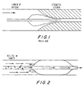
- the balloon may bunch up, i.e., fold up longitudinally like an accordion, as shown in Fig. 1, and the catheter will not pass through the stenosis.
- a balloon catheter in which the balloon is bonded to the shaft for its entire length would eliminate this problem.
- Inflation of a concentrically mounted balloon results in a uniform force circumferentially applied to the stenotic lesion.
- the structure or morphology of the lesion is rarely uniform, and harder portions will require more force to dilate than will softer areas. This has necessitated the practice of inflating the balloon at very high pressures, causing overdistention, dissection, and tearing.
- a dilatation balloon may rupture, resulting in serious complications.
- a balloon catheter which can apply a focused, variable force for dilatation, at lower pressures.
- the shaft segment within the balloon may be a solid wire (Frisbee and Samson), or it may be a hollow and open-ended tube which allows the catheter to be moved over a guidewire (Simpson/Robert, Bonzel, Yock).
- the catheter of Mueller et al. a representative structure of which is shown in Fig. 2, has small holes in the shaft proximal to the balloon to allow blood to enter, for the intended purpose of allowing blood to perfuse the vessel while the balloon is inflated. Since the blood impacts the balloon, turns to enter the small holes in the shaft, and then turns again to exit the catheter in the proximal direction, this design promotes turbulent blood flow of the type that often results in hemolysis and thrombosis.
- the balloon of Walinsky is porous and is intended to deliver a therapeutic agent to the lesion while the balloon is inflated. Since the inflation pressure of the balloon is often high to effect dilatation, the drug may exit the pores in the balloon at a velocity that would injure or even perforate the vessel.
- a balloon dilatation catheter with a lumen positioned external to the balloon, such that the lumen could be used for therapeutic means (e.g., blood perfusion, drug delivery) during balloon inflation.
- therapeutic means e.g., blood perfusion, drug delivery
- Document US-A-4,958,634 on which the pre-characterising part of claim 1 is based describes a catheter with a lumen extending its full length for a guidewire and a number of further lumens supplying eccentrically placed dilatation balloons. This catheter enables the treatment of multiple lesions with a single catheter, thus obviating the need for catheter exchange.
- a balloon dilatation catheter which comprises a catheter shaft defining a first, inflation lumen and a second lumen, each of said first and second lumens having proximal and distal ends, and an inflatable dilatation balloon having proximal and distal ends, wherein the distal end of the first lumen opens into and is in fluid communication with the interior of the dilatation balloon, the section of the second lumen distal to the proximal end of the dilatation balloon being exterior to the dilatation balloon, the distal end of the second lumen being open and distal to the distal end of the dilatation balloon, and the second lumen being sufficiently linear to allow the catheter to be slidingly advanced over a guidewire characterised in that the proximal end of the second lumen is open and is located substantially distal to the proximal end of the first lumen.
- the catheter comprises two substantially coextensive lumens of equal length, wherein the distal portion of one lumen terminates in a dilatation balloon, and the second lumen is open at its distal end and is interrupted near its distal end to provide an opening for a guidewire that extends distally through the open distal end.
- the second lumen may have a pushing wire that extends from the proximal portion of the catheter to a point proximal, adjacent, or distal to the opening.
- the second lumen engages a radiopaque marker that functions to help break plaque as well as to provide means for locating the position of the catheter balloon within the vessel.
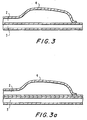
- Figs. 3 and 3a depict the distal portion of a balloon dilatation catheter 1 having coextensively extending lumens 2 and 3.
- Lumen 2 terminates in a dilatation balloon 4 which is inflated and deflated through lumen 2.
- Lumen 3 may be bonded to balloon 4 as shown in Fig. 3a or preferably formed from one piece as shown in Fig. 3.
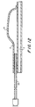
- lumen 3 contains pushing wire 5, which extends from the proximal end (not shown) of catheter 1 to a position 6 proximal, adjacent to, or within balloon 4.
- the distal portion of pushing wire 5 is secured by closure, e.g., heat-shrinking of lumen 3, by insertion of a plug, or by other holding means.
- the distal portion 7 of pushing wire 5 is preferably tapered distally to provide a smooth transition in axial stiffness.
- the pushing wire 5 will become less stiff as the diameter of pushing wire 5 narrows in the distal direction.
- the tapering is substantially linear over the distal portion of the pushing wire 5.
- the tapering may be stepped, in discrete reductions, or otherwise nonlinear.
- the distal portion 10 of lumen 3 is enlarged, beginning at a location proximal to the balloon. Opening 9 allows a guidewire 8 to enter and extend distally through the open distal end of lumen 3.
- a lubricious lining 14 and a radiopaque marker 15 are included in the enlarged section 10. Lubricious lining 14 may function to hold the distal portion of pushing wire 5 between the inner surface of lumen 3 and the outer surface of lubricious lining 14.
- Fig. 5 represents a cross-sectional view showing how lumens 2 and 3 relate to one another and how pushing wire 5 is positioned within lumen 3.
- Lumen walls 12 and 13 can each have a thickness of from 7.62 to 508 micrometres (0.3 to 20 mil), preferably from 12.7 to 254 microrrctres (0.5 to 10 mil).
- Fig. 6 represents a cross-sectional view through the center of the balloon of this embodiment. This figure shows how the balloon relates to the enlarged section 10 of lumen 3, and to guidewire 8.
- a radiopaque marker 15 is sandwiched between the outer surface of lubricious lining 14 and the inner surface of the wall of enlarged section 10.
- the catheter may have more than one external lumen, preferably two.
- Figs. 5 and 6 each appear to represent a one-piece construction, as shown in Fig. 3a, lumens 2 and 3 may be defined by tubes adhesively or otherwise bonded together.
- Figs. 7 and 8 show dilatation balloon catheters, according to the prior art and the invention, respectively, in the application of dilating a stenotic lesion 40 in a blood vessel 41.
- F force
- the pressure that is exerted against the lesion is proportional to this force, F, divided by the area upon which the force is acting (the "contact area").
- the contact area is equal to the lateral surface area of the balloon 42.
- the contact area is not coextensive with the lateral surface area of the balloon 4.
- the contact area is equal to the lateral surface area of balloon 4. However, at another point, the contact area is equal to the lateral surface area of the tube that defines lumen 3. Since lumen 3 has a much smaller area of contact against the lesion than does the balloon 4, the pressure exerted at that point is much greater. Therefore, unnecessarily high balloon inflation pressures can be avoided since this design accentuates and focuses the radial force against the lesion adjacent to lumen 3.
- the pressure exerted against the portion of the lesion adjacent lumen 3 is greater than that exerted against the portion of the lesion adjacent to the balloon.
- Figs. 9 to 11 provide for alternate means to achieve the concentration or focusing of the dilating force.
- the section in the eccentric lumen 3 that is associated with the dilatation, i.e., adjacent to the balloon, has means that form an even smaller contact area with the lesion.
- Such means provide somewhat of a sharp edge, similar to a knife edge, to cut the lesion as the balloon is inflated.
- the metal band 17 that serves as a radiopaque marker has a triangular shape, and is positioned within lumen 3 such that one side of the triangle 17 is located under the balloon, and the opposite apex of the triangle is against the lesion.
- Figs. 9 the embodiment of Figs.
- a section of lumen 3 under the balloon is cut away.
- a triangularly shaped wire or guidewire, or some other knife edge or cutting instrument 19, can be safely passed through lumen 3 and positioned directly at the lesion through the opening 18. This opening in lumen 3 will also allow drugs to be delivered directly to the lesion.
- the rapid exchange embodiment of the invention can also function as an improved, more efficient perfusion catheter.
- blood With the guidewire removed from lumen 3, blood will flow through lumen 3 while the balloon is inflated. Since the openings in lumen 3 are collinear with the artery, i.e., collinear with the direction of the flow of blood, and are large (compared to the side-hole openings of previously described perfusion catheters), there will be significantly less turbulence in the blood flow through lumen 3. As a result, there will be significantly greater blood flow, and reduced hemolysis compared to previously described perfusion catheters.
- a guidewire may be left in place (i.e., in a lumen) while blood flows through an open lumen.
- the distal section of a balloon dilatation catheter comprises at least two substantially, longitudinal coextensive lumens wherein one lumen terminates in a dilatation balloon and at least one other lumen is positioned outside, i.e., eccentric to the balloon.
- the lumen walls 12 and 13 are comprised of materials conventional to balloon dilatation catheters. Suitable materials include polyolefins such as polyethylene, polyethylene terepthalate, polyurethanes, polyesters, and various copolymers thereof.
- pushing wire 5 can be made from any rigid, medically acceptable material suitable for such use, including, but not limited to wires or hypotubes comprised of stainless steel or other rigid materials.
- the construction according to the invention leads to flexibility in product design.
- the choice of pushing wire allows the designer to impart various features to the catheter in the form of various flexibility and pushability combinations.
- a hollow pushing wire, or deletion or removal of the pushing wire would facilitate infusion of fluids, drugs, and/or contrast media through the catheter into the distal vasculature.
- lumen 2, used to inflate the balloon could have a composite structure, for example, with a distal segment coextensive with lumen 3 as described above, and a proximal segment made from a hollow wire, such as a hypotube 50. An example of such an embodiment is shown in Fig. 12.
- catheter 1 may have at least one additional, coextensive lumen that would similarly facilitate infusion of liquids, drugs and/or contrast media.
- catheter 1 with a third, coextensive lumen open at its distal end could have several possible applications.
- a lubricious coating or a section of thin tubing 14 of lubricious material is sealed into enlarged section 10.
- a lubricious coating or a section of thin tubing 14 of lubricious material is sealed into enlarged section 10.
- materials suitable for this purpose such as polytetrafluoroethylene (available as TEFLON® from duPont), polyethylenes, polysiloxanes, etc.
- the tubing section 14 can hold the distal portion 7 of pushing wire 5, as well as radiopaque marker 15 or 17, in position.
- a slitting means (not shown) is mounted proximally on guidewire 8. Then, as the catheter 1 is withdrawn, the enlarged section engages the slitting means, the enlarged section 10 is slit, and catheter 1 is separated from guidewire 8. This would eliminate the requirement for the operator to change hands as catheter 1 is removed.
- the catheter 1 may have visual length markings along its shaft that would enable the operator to predict when the catheter 1 would exit the guiding catheter into the vasculature. This would reduce the fluoroscope time.
- the preferred design would put the markings directly on the pushing wire 5 (heat shrink tubing rings, inks, paints, etc.). Since pushing wire 5 is encapsulated within the second lumen 3, the markings would not be exposed to the patient (i.e., markings would not come off, and materials which could be toxic if exposed may be used).
- preparation of a catheter 1 according to the invention can be carried out by methods and techniques known to or discernible by those skilled in the art. Furthermore, preparation of a catheter 1 is described and taught in Applicant's co-pending, commonly assigned, U.S. Patent Application Serial No. 07/969,946, filed October 30, 1992, and U.S. Patent Application Serial No. 08/087,428, filed July 2, 1993.
- Guidewire 8 may be a conventional guidewire, preferably a spring guidewire, as is well known. Typical guidewires are shown in U.S. Patents Nos. 4,757,827, 4,815,478, 4,813,434, 4,619,274, 4,554,929, 4,545,390, 4,538,622, 3,906,938, 3,973,556, and 4,719,924, all of which are incorporated herein by reference.
- the shaft of guidewire 8 could be solid or hollow, such as a hypotube, with an open distal end, to facilitate drug infusion.
- angioplasty apparatus of the invention an embodiment of which is shown in Fig. 4, may now be briefly described as follows: A guiding catheter is inserted into the coronary artery in a conventional manner. The guidewire 8 is then introduced into the guiding catheter and advanced to and across the lesion. Now, the balloon dilatation catheter is inserted onto the guidewire and then advanced along the guidewire 8 to and across the lesion.
- the balloon 4 After the balloon 4 has crossed the stenosis or lesion, the balloon 4 can be inflated in a conventional manner by introducing a radiopaque contrast liquid through the lumen 2. After the inflation has occurred and the desired operation has been performed by enlarging the opening in the stenosis, the balloon dilatation catheter 1 can be removed very rapidly by holding the guidewire 8 stationary and withdrawing the balloon dilation catheter.
- the balloon dilatation catheter can be removed and thereafter the guiding catheter can be removed.
Description
- This invention is directed to a catheter that utilizes a balloon to dilate structures or stenoses within the human body. More particularly, this invention is directed to a dilatation catheter having an eccentrically positioned balloon.
- The use of balloon catheters to treat strictures, stenoses, or narrowings within various parts of the human body is well known and is the subject of many patents. For example, Grüntzig, U.S. Patent No. 4,195,637, Simpson and Robert, U.S. Patent No. 4,323,071, Bonzel, U.S. Patent No. 4,762,129, Yock, U.S. Patents Nos. 5,040,548 and 5,061,273, Frisbee and Samson, U.S. Patents Nos. 4,573,470 and 4,619,262, Chin et al., U.S. Patent No. 4,493,711, Mueller et al., U.S. Patent No. 4,790,315, Walinsky, U.S. Patents Nos. 4,641,649 and 4,643,186, and others, teach that balloon catheters can be used to dilate stenoses in blood vessels. In each design, the balloon has a generally cylindrical shape, positioned in a concentric manner in relation to the catheter shaft, and bonded distally and/or proximally to the shaft. When an operator attempts to pass a dilatation balloon having such a design through a very tight opening in a stenosis, the balloon may bunch up, i.e., fold up longitudinally like an accordion, as shown in Fig. 1, and the catheter will not pass through the stenosis. A balloon catheter in which the balloon is bonded to the shaft for its entire length would eliminate this problem.
- Inflation of a concentrically mounted balloon results in a uniform force circumferentially applied to the stenotic lesion. However, the structure or morphology of the lesion is rarely uniform, and harder portions will require more force to dilate than will softer areas. This has necessitated the practice of inflating the balloon at very high pressures, causing overdistention, dissection, and tearing. In addition, at high pressures, a dilatation balloon may rupture, resulting in serious complications. Thus, there is a need for a balloon catheter which can apply a focused, variable force for dilatation, at lower pressures.
- In prior art dilatation balloon catheters, the shaft segment within the balloon may be a solid wire (Frisbee and Samson), or it may be a hollow and open-ended tube which allows the catheter to be moved over a guidewire (Simpson/Robert, Bonzel, Yock). The catheter of Mueller et al., a representative structure of which is shown in Fig. 2, has small holes in the shaft proximal to the balloon to allow blood to enter, for the intended purpose of allowing blood to perfuse the vessel while the balloon is inflated. Since the blood impacts the balloon, turns to enter the small holes in the shaft, and then turns again to exit the catheter in the proximal direction, this design promotes turbulent blood flow of the type that often results in hemolysis and thrombosis. The balloon of Walinsky is porous and is intended to deliver a therapeutic agent to the lesion while the balloon is inflated. Since the inflation pressure of the balloon is often high to effect dilatation, the drug may exit the pores in the balloon at a velocity that would injure or even perforate the vessel.
- Thus, there is a need for a balloon dilatation catheter with a lumen positioned external to the balloon, such that the lumen could be used for therapeutic means (e.g., blood perfusion, drug delivery) during balloon inflation.
- Document US-A-4,958,634 on which the pre-characterising part of claim 1 is based describes a catheter with a lumen extending its full length for a guidewire and a number of further lumens supplying eccentrically placed dilatation balloons. This catheter enables the treatment of multiple lesions with a single catheter, thus obviating the need for catheter exchange.
- It is an object of the invention to provide a balloon dilatation catheter that has one or more lumens positioned exterior to the balloon.
- It is also an object of the invention to provide a balloon dilatation catheter in which the balloon is eccentric to the shaft.
- It is a further object of the invention to provide a balloon dilatation catheter in which the balloon is eccentric to a guidewire lumen.
- It is yet a further object of the invention to provide a balloon dilatation catheter in which the dilating force applied to a stricture is focused and nonuniform around its circumference.
- It is furthermore an object of the invention to provide a balloon dilatation catheter in which the balloon is attached to the shaft of the catheter for the entire length of the balloon.
-
- Fig. 1 is a cross-sectional representation of the distal portion of a prior art balloon catheter attempting to cross a tight stenosis;
- Fig. 2 is a cross-sectional view of a prior art perfusion catheter;
- Figs. 3 and 3a are each a cross-sectional view of the distal portion of the invention illustrating the basic structure of the design.
- Fig. 4 is a cross-sectional view of the distal portion of an embodiment of a dilatation balloon catheter according to the invention;
- Fig. 5 is a cross-sectional view in the proximal direction of the embodiment shown in Fig. 4;
- Fig. 6 is a cross-sectional view through the balloon of the embodiment shown in Fig. 4;
- Figs. 7 and 8 are representations of cross-sections of dilatation balloon catheters according to the prior art and the invention, respectively, within a stricture to be dilated.
- Fig. 9 is a cross-sectional view of the distal portion of another embodiment of the invention;
- Fig. 10 is a cross-sectional view of a further embodiment of the invention;
- Fig. 11 is a cross-sectional view of the line 11-11 of the embodiment shown in Fig. 10; and
- Fig. 12 is a cross-sectional view of a yet further embodiment of the invention.
-
- According to the present invention there is provided a balloon dilatation catheter which comprises a catheter shaft defining a first, inflation lumen and a second lumen, each of said first and second lumens having proximal and distal ends, and an inflatable dilatation balloon having proximal and distal ends, wherein the distal end of the first lumen opens into and is in fluid communication with the interior of the dilatation balloon, the section of the second lumen distal to the proximal end of the dilatation balloon being exterior to the dilatation balloon, the distal end of the second lumen being open and distal to the distal end of the dilatation balloon, and the second lumen being sufficiently linear to allow the catheter to be slidingly advanced over a guidewire characterised in that the proximal end of the second lumen is open and is located substantially distal to the proximal end of the first lumen.
- In a preferred embodiment, the catheter comprises two substantially coextensive lumens of equal length, wherein the distal portion of one lumen terminates in a dilatation balloon, and the second lumen is open at its distal end and is interrupted near its distal end to provide an opening for a guidewire that extends distally through the open distal end. In this embodiment, the second lumen may have a pushing wire that extends from the proximal portion of the catheter to a point proximal, adjacent, or distal to the opening. Preferably the second lumen engages a radiopaque marker that functions to help break plaque as well as to provide means for locating the position of the catheter balloon within the vessel.
- The invention can perhaps be better appreciated by making reference to the drawings. The basic structure of the design is shown in Figs. 3 and 3a. Figs. 3 and 3a depict the distal portion of a balloon dilatation catheter 1 having coextensively extending
lumens Lumen 2 terminates in adilatation balloon 4 which is inflated and deflated throughlumen 2.Lumen 3 may be bonded toballoon 4 as shown in Fig. 3a or preferably formed from one piece as shown in Fig. 3. - In a preferred embodiment, shown in Fig. 4,
lumen 3 contains pushingwire 5, which extends from the proximal end (not shown) of catheter 1 to aposition 6 proximal, adjacent to, or withinballoon 4. The distal portion of pushingwire 5 is secured by closure, e.g., heat-shrinking oflumen 3, by insertion of a plug, or by other holding means. Also, the distal portion 7 of pushingwire 5 is preferably tapered distally to provide a smooth transition in axial stiffness. The pushingwire 5 will become less stiff as the diameter of pushingwire 5 narrows in the distal direction. The tapering is substantially linear over the distal portion of the pushingwire 5. Optionally, instead of linear tapering, the tapering may be stepped, in discrete reductions, or otherwise nonlinear. - The
distal portion 10 oflumen 3 is enlarged, beginning at a location proximal to the balloon. Opening 9 allows aguidewire 8 to enter and extend distally through the open distal end oflumen 3. Preferably, alubricious lining 14 and aradiopaque marker 15 are included in the enlargedsection 10.Lubricious lining 14 may function to hold the distal portion of pushingwire 5 between the inner surface oflumen 3 and the outer surface oflubricious lining 14. - Fig. 5 represents a cross-sectional view showing how
lumens wire 5 is positioned withinlumen 3.Lumen walls - Fig. 6 represents a cross-sectional view through the center of the balloon of this embodiment. This figure shows how the balloon relates to the
enlarged section 10 oflumen 3, and toguidewire 8. Preferably, aradiopaque marker 15 is sandwiched between the outer surface oflubricious lining 14 and the inner surface of the wall ofenlarged section 10. In an additional embodiment, the catheter may have more than one external lumen, preferably two. - Although Figs. 5 and 6 each appear to represent a one-piece construction, as shown in Fig. 3a,
lumens - Figs. 7 and 8 show dilatation balloon catheters, according to the prior art and the invention, respectively, in the application of dilating a
stenotic lesion 40 in ablood vessel 41. As the balloon of a dilatation catheter is inflated, it exerts a force, F, that corresponds to the inflation pressure. The pressure that is exerted against the lesion is proportional to this force, F, divided by the area upon which the force is acting (the "contact area"). As shown in Fig. 7, for prior art balloon catheters the contact area is equal to the lateral surface area of theballoon 42. For the catheter of this invention (Fig. 8) the contact area is not coextensive with the lateral surface area of theballoon 4. At one point the contact area is equal to the lateral surface area ofballoon 4. However, at another point, the contact area is equal to the lateral surface area of the tube that defineslumen 3. Sincelumen 3 has a much smaller area of contact against the lesion than does theballoon 4, the pressure exerted at that point is much greater. Therefore, unnecessarily high balloon inflation pressures can be avoided since this design accentuates and focuses the radial force against the lesion adjacent tolumen 3. - The concepts discussed above for Fig. 8 can be represented mathematically by the formulae shown below:
- P = pressure exerted against a lesion at a given point;
- F = Force generated by inflating the balloon; and
- A = Contact area. At the location where the
-
- At the location where the outer wall of
lumen 3 makes contact with thelesion 40, the pressure exerted against the lesion islumen 3. - Since the lateral surface area of the balloon is much greater than that of the outer wall of
lumen 3, - The ratio of PL3 to PB is determined by dividing equation (3) by equation (2) and substituting equation (4)
- Therefore, for a given balloon inflation pressure, the pressure exerted against the portion of the lesion
adjacent lumen 3 is greater than that exerted against the portion of the lesion adjacent to the balloon. - Additional embodiments, illustrated in Figs. 9 to 11, provide for alternate means to achieve the concentration or focusing of the dilating force. For both of these embodiments, the section in the
eccentric lumen 3 that is associated with the dilatation, i.e., adjacent to the balloon, has means that form an even smaller contact area with the lesion. Such means provide somewhat of a sharp edge, similar to a knife edge, to cut the lesion as the balloon is inflated. In Fig. 9, themetal band 17 that serves as a radiopaque marker has a triangular shape, and is positioned withinlumen 3 such that one side of thetriangle 17 is located under the balloon, and the opposite apex of the triangle is against the lesion. In the embodiment of Figs. 10 and 11, a section oflumen 3 under the balloon is cut away. A triangularly shaped wire or guidewire, or some other knife edge or cuttinginstrument 19, can be safely passed throughlumen 3 and positioned directly at the lesion through theopening 18. This opening inlumen 3 will also allow drugs to be delivered directly to the lesion. - The rapid exchange embodiment of the invention, for example, the embodiment shown in Fig. 4, can also function as an improved, more efficient perfusion catheter. With the guidewire removed from
lumen 3, blood will flow throughlumen 3 while the balloon is inflated. Since the openings inlumen 3 are collinear with the artery, i.e., collinear with the direction of the flow of blood, and are large (compared to the side-hole openings of previously described perfusion catheters), there will be significantly less turbulence in the blood flow throughlumen 3. As a result, there will be significantly greater blood flow, and reduced hemolysis compared to previously described perfusion catheters. Moreover, in an embodiment that employs more than one eccentric lumen, and/or an embodiment like that of Fig. 4 in which pushingwire 5 is replaced with a slidable guidewire, a guidewire may be left in place (i.e., in a lumen) while blood flows through an open lumen. - According to the invention, the distal section of a balloon dilatation catheter comprises at least two substantially, longitudinal coextensive lumens wherein one lumen terminates in a dilatation balloon and at least one other lumen is positioned outside, i.e., eccentric to the balloon.
- The
lumen walls wire 5 can be made from any rigid, medically acceptable material suitable for such use, including, but not limited to wires or hypotubes comprised of stainless steel or other rigid materials. - The construction according to the invention leads to flexibility in product design. For example, the choice of pushing wire allows the designer to impart various features to the catheter in the form of various flexibility and pushability combinations. Also, a hollow pushing wire, or deletion or removal of the pushing wire, would facilitate infusion of fluids, drugs, and/or contrast media through the catheter into the distal vasculature. Similarly,
lumen 2, used to inflate the balloon, could have a composite structure, for example, with a distal segment coextensive withlumen 3 as described above, and a proximal segment made from a hollow wire, such as ahypotube 50. An example of such an embodiment is shown in Fig. 12. Further, it is within the scope of the invention that catheter 1 may have at least one additional, coextensive lumen that would similarly facilitate infusion of liquids, drugs and/or contrast media. For example, a catheter 1 with a third, coextensive lumen open at its distal end could have several possible applications. - In a preferred embodiment of the invention, as shown in Fig. 4, a lubricious coating or a section of
thin tubing 14 of lubricious material is sealed intoenlarged section 10. There are several known materials suitable for this purpose, such as polytetrafluoroethylene (available as TEFLON® from duPont), polyethylenes, polysiloxanes, etc. In this embodiment thetubing section 14 can hold the distal portion 7 of pushingwire 5, as well asradiopaque marker - According to a another embodiment of the invention a slitting means (not shown) is mounted proximally on
guidewire 8. Then, as the catheter 1 is withdrawn, the enlarged section engages the slitting means, theenlarged section 10 is slit, and catheter 1 is separated fromguidewire 8. This would eliminate the requirement for the operator to change hands as catheter 1 is removed. - The catheter 1 may have visual length markings along its shaft that would enable the operator to predict when the catheter 1 would exit the guiding catheter into the vasculature. This would reduce the fluoroscope time. The preferred design would put the markings directly on the pushing wire 5 (heat shrink tubing rings, inks, paints, etc.). Since pushing
wire 5 is encapsulated within thesecond lumen 3, the markings would not be exposed to the patient (i.e., markings would not come off, and materials which could be toxic if exposed may be used). - The preparation of a catheter 1 according to the invention can be carried out by methods and techniques known to or discernible by those skilled in the art. Furthermore, preparation of a catheter 1 is described and taught in Applicant's co-pending, commonly assigned, U.S. Patent Application Serial No. 07/969,946, filed October 30, 1992, and U.S. Patent Application Serial No. 08/087,428, filed July 2, 1993.
-
Guidewire 8 may be a conventional guidewire, preferably a spring guidewire, as is well known. Typical guidewires are shown in U.S. Patents Nos. 4,757,827, 4,815,478, 4,813,434, 4,619,274, 4,554,929, 4,545,390, 4,538,622, 3,906,938, 3,973,556, and 4,719,924, all of which are incorporated herein by reference. In addition, the shaft ofguidewire 8 could be solid or hollow, such as a hypotube, with an open distal end, to facilitate drug infusion. - Operation and use of the angioplasty apparatus of the invention, an embodiment of which is shown in Fig. 4, may now be briefly described as follows: A guiding catheter is inserted into the coronary artery in a conventional manner. The
guidewire 8 is then introduced into the guiding catheter and advanced to and across the lesion. Now, the balloon dilatation catheter is inserted onto the guidewire and then advanced along theguidewire 8 to and across the lesion. - After the
balloon 4 has crossed the stenosis or lesion, theballoon 4 can be inflated in a conventional manner by introducing a radiopaque contrast liquid through thelumen 2. After the inflation has occurred and the desired operation has been performed by enlarging the opening in the stenosis, the balloon dilatation catheter 1 can be removed very rapidly by holding theguidewire 8 stationary and withdrawing the balloon dilation catheter. - If it is ascertained by the operator that additional dilatation of the stenosis is desired and that a larger balloon should be inserted into the stenosis, this can be accomplished very rapidly by selecting the desired size of balloon dilation catheter and repeating the aforementioned procedure. The balloon of the new dilatation catheter can be inflated in the same manner as hereinbefore described. If necessary, even another exchange procedure can be readily accomplished in the same manner as hereinbefore described utilizing a still larger balloon dilatation catheter if that turns out to be necessary.
- After the desired amount of dilation of the stenosis or lesion has been accomplished, the balloon dilatation catheter can be removed and thereafter the guiding catheter can be removed.
- As would be appreciated by those skilled in the art, for embodiments in which
lumens - The preceding specific embodiments are illustrative of the practice of the invention. It is to be understood, however, that other expedients known to those skilled in the art or disclosed herein, may be employed without departing from the scope of the appended claims.
Claims (10)
- A balloon dilatation catheter (1) which comprises:characterised in thata catheter shaft defining a first, inflation lumen (2) and a second lumen (3, 10), each of said first and second lumens having proximal and distal ends, andan inflatable dilatation balloon (4) having proximal and distal ends,wherein the distal end of the first lumen (2) opens into and is in fluid communication with the interior of the dilatation balloon (4),the section of the second lumen distal to the proximal end of the dilatation balloon being exterior to the dilatation balloon,the distal end of the second lumen being open and distal to the distal end of the dilatation balloon, andthe second lumen being sufficiently linear to allow the catheter to be slidingly advanced over a guidewire (8)
the proximal end of the second lumen (3, 10) is open and is located substantially distal to the proximal end of the first lumen. - The catheter of claim 1, wherein the diameter of the second lumen (3, 10) is smaller than the diameter of the inflated dilatation balloon (4).
- The catheter of claim 1, wherein the balloon (4) is bonded axially along its entire length to the second lumen.
- The catheter of claim 1, wherein the balloon (4) and the second lumen (3, 10) are made from one piece.
- The catheter of claim 1, wherein the first inflation lumen (2) is a metal hypotube.
- The catheter of claim 1, wherein a radiopaque marker is located within the second lumen (3, 10) at a point between the proximal and distal ends of the balloon (4).
- The catheter of claim 6, wherein the radiopaque marker has a triangular shape.
- The catheter of claim 6, wherein the radiopaque marker has an outwardly extending sharp edge opposite the balloon.
- A balloon dilatation catheter system which comprises one or more catheters of claim 1 and a guidewire.
- The system of claim 9, wherein each catheter has a dilatation balloon of varying size.
Applications Claiming Priority (3)
| Application Number | Priority Date | Filing Date | Title |
|---|---|---|---|
| US08/111,304 US5413557A (en) | 1993-08-24 | 1993-08-24 | Dilatation catheter with eccentric balloon |
| US111304 | 1993-08-24 | ||
| PCT/US1994/009806 WO1995005865A1 (en) | 1993-08-24 | 1994-08-24 | Dilatation catheter with eccentric balloon |
Publications (3)
| Publication Number | Publication Date |
|---|---|
| EP0715531A1 EP0715531A1 (en) | 1996-06-12 |
| EP0715531A4 EP0715531A4 (en) | 1997-02-05 |
| EP0715531B1 true EP0715531B1 (en) | 2001-11-21 |
Family
ID=22337726
Family Applications (1)
| Application Number | Title | Priority Date | Filing Date |
|---|---|---|---|
| EP94927289A Expired - Lifetime EP0715531B1 (en) | 1993-08-24 | 1994-08-24 | Dilatation catheter with eccentric balloon |
Country Status (7)
| Country | Link |
|---|---|
| US (2) | US5413557A (en) |
| EP (1) | EP0715531B1 (en) |
| JP (1) | JPH09501852A (en) |
| AU (1) | AU7678094A (en) |
| CA (1) | CA2170361C (en) |
| DE (1) | DE69429181T2 (en) |
| WO (1) | WO1995005865A1 (en) |
Families Citing this family (80)
| Publication number | Priority date | Publication date | Assignee | Title |
|---|---|---|---|---|
| US5766151A (en) * | 1991-07-16 | 1998-06-16 | Heartport, Inc. | Endovascular system for arresting the heart |
| US5645529A (en) * | 1993-03-11 | 1997-07-08 | C. R. Bard, Inc. | Devices for selectively directing inflation devices |
| US5948489A (en) * | 1994-03-03 | 1999-09-07 | Cordis Corporation | Catheter having extruded, flexible, pliable and compliant marker band |
| US5683345A (en) * | 1994-10-27 | 1997-11-04 | Novoste Corporation | Method and apparatus for treating a desired area in the vascular system of a patient |
| US5899882A (en) | 1994-10-27 | 1999-05-04 | Novoste Corporation | Catheter apparatus for radiation treatment of a desired area in the vascular system of a patient |
| US6503185B1 (en) | 1994-10-27 | 2003-01-07 | Novoste Corporation | Method and apparatus for treating a desired area in the vascular system of a patient |
| US5836957A (en) * | 1994-12-22 | 1998-11-17 | Devices For Vascular Intervention, Inc. | Large volume atherectomy device |
| US5667493A (en) * | 1994-12-30 | 1997-09-16 | Janacek; Jaroslav | Dilation catheter |
| US5540798A (en) * | 1995-02-02 | 1996-07-30 | Demaio; Samuel J. | Balloon catheter |
| EP0785807A4 (en) * | 1995-06-16 | 2000-01-12 | Cordis Corp | Stent delivery system |
| FR2738489A1 (en) * | 1995-09-12 | 1997-03-14 | Balt Extrusion | Surgical occluding balloon catheter |
| US5690642A (en) | 1996-01-18 | 1997-11-25 | Cook Incorporated | Rapid exchange stent delivery balloon catheter |
| US6071285A (en) * | 1996-03-25 | 2000-06-06 | Lashinski; Robert D. | Rapid exchange folded balloon catheter and stent delivery system |
| US6544276B1 (en) * | 1996-05-20 | 2003-04-08 | Medtronic Ave. Inc. | Exchange method for emboli containment |
| US6270477B1 (en) * | 1996-05-20 | 2001-08-07 | Percusurge, Inc. | Catheter for emboli containment |
| US5916194A (en) * | 1996-05-24 | 1999-06-29 | Sarcos, Inc. | Catheter/guide wire steering apparatus and method |
| JPH10258061A (en) * | 1997-03-19 | 1998-09-29 | Asahi Optical Co Ltd | Treating tool for endoscope |
| US6056721A (en) * | 1997-08-08 | 2000-05-02 | Sunscope International, Inc. | Balloon catheter and method |
| US20030233068A1 (en) * | 1997-09-18 | 2003-12-18 | Swaminathan Jayaraman | Delivery mechanism for balloons, drugs, stents and other physical/mechanical agents and method of use |
| US6056722A (en) * | 1997-09-18 | 2000-05-02 | Iowa-India Investments Company Limited Of Douglas | Delivery mechanism for balloons, drugs, stents and other physical/mechanical agents and methods of use |
| US5961536A (en) * | 1997-10-14 | 1999-10-05 | Scimed Life Systems, Inc. | Catheter having a variable length balloon and method of using the same |
| US6099926A (en) * | 1997-12-12 | 2000-08-08 | Intella Interventional Systems, Inc. | Aliphatic polyketone compositions and medical devices |
| US6093463A (en) * | 1997-12-12 | 2000-07-25 | Intella Interventional Systems, Inc. | Medical devices made from improved polymer blends |
| US6099497A (en) * | 1998-03-05 | 2000-08-08 | Scimed Life Systems, Inc. | Dilatation and stent delivery system for bifurcation lesions |
| US6780199B2 (en) | 1998-05-15 | 2004-08-24 | Advanced Cardiovascular Systems, Inc. | Enhanced stent delivery system |
| EP1083960A4 (en) * | 1998-05-15 | 2001-09-12 | Medgination Inc | Enhanced balloon dilatation system |
| US6447501B1 (en) | 1998-05-15 | 2002-09-10 | X Technologies Inc. | Enhanced stent delivery system |
| US6740104B1 (en) * | 1998-05-15 | 2004-05-25 | Advanced Cardiovascular Systems, Inc. | Enhanced catheter with alignment means |
| US6740082B2 (en) | 1998-12-29 | 2004-05-25 | John H. Shadduck | Surgical instruments for treating gastro-esophageal reflux |
| AU5196999A (en) | 1998-08-17 | 2000-03-06 | Kazuhiro Noda | Operation balloon |
| DK1255506T3 (en) * | 2000-02-18 | 2004-01-05 | E V R Endovascular Res Es S A | Endolumenal device for delivering and placing an endolumenal expandable prosthesis |
| US6302865B1 (en) | 2000-03-13 | 2001-10-16 | Scimed Life Systems, Inc. | Intravascular guidewire with perfusion lumen |
| JP2004535847A (en) * | 2001-03-14 | 2004-12-02 | イー・ブイ・アール・エンドバスキュラー・リサーチイズ・エス・エー | Vascular catheter guide wire support |
| US20030125761A1 (en) * | 2001-05-08 | 2003-07-03 | Meens Hendrik Jozef Maria | Balloon catheter |
| US20030191436A1 (en) * | 2002-04-05 | 2003-10-09 | Horvers Ronald Adrianus Maria | Balloon catheter |
| US6679860B2 (en) | 2001-06-19 | 2004-01-20 | Medtronic Ave, Inc. | Intraluminal therapy catheter with inflatable helical member and methods of use |
| AU2002350164A1 (en) * | 2001-11-08 | 2003-05-19 | William D. Hare | Rapid exchange catheter with stent deployment, therapeutic infusion, and lesion sampling features |
| US7029450B2 (en) * | 2001-12-14 | 2006-04-18 | Boston Scientific Scimed, Inc. | Dilation catheter assembly and related methods |
| AU2003241129A1 (en) * | 2002-06-13 | 2003-12-31 | Existent, Inc. | Guidewire system |
| AU2003231910A1 (en) * | 2002-06-13 | 2003-12-31 | Existent, Inc. | Mechanical structures and implants using said structures |
| US6997899B2 (en) * | 2002-12-17 | 2006-02-14 | Boston Scientific Scimed, Inc, | Rapid exchange dilation catheter for non-vascular applications |
| US7300415B2 (en) * | 2002-12-20 | 2007-11-27 | Advanced Cardiovascular Systems, Inc. | Balloon catheter having an external guidewire |
| DE50209306D1 (en) | 2002-12-31 | 2007-03-08 | Abbott Lab Vascular Entpr Ltd | Catheter with a more flexible area between stem and tip, and method of making the same |
| AU2003219392A1 (en) * | 2003-04-24 | 2004-11-19 | Invatec S.R.L. | Balloon structure and balloon catheter |
| US7473239B2 (en) * | 2003-08-25 | 2009-01-06 | The University Of Texas System | Single expandable double lumen cannula assembly for veno-venous ECMO |
| US7695491B2 (en) * | 2003-12-01 | 2010-04-13 | Ev3 Inc. | Rapid exchange catheters with tandem lumens |
| US7468051B2 (en) * | 2004-03-02 | 2008-12-23 | Boston Scientific Scimed, Inc. | Occlusion balloon catheter with external inflation lumen |
| US8252014B2 (en) * | 2004-03-03 | 2012-08-28 | Innovational Holdings Llc. | Rapid exchange balloon catheter with braided shaft |
| US9050437B2 (en) * | 2004-03-04 | 2015-06-09 | YMED, Inc. | Positioning device for ostial lesions |
| US7753951B2 (en) * | 2004-03-04 | 2010-07-13 | Y Med, Inc. | Vessel treatment devices |
| US7780715B2 (en) * | 2004-03-04 | 2010-08-24 | Y Med, Inc. | Vessel treatment devices |
| US7766951B2 (en) * | 2004-03-04 | 2010-08-03 | Y Med, Inc. | Vessel treatment devices |
| US7785318B2 (en) * | 2004-05-27 | 2010-08-31 | Abbott Laboratories | Catheter having plurality of stiffening members |
| US7794448B2 (en) * | 2004-05-27 | 2010-09-14 | Abbott Laboratories | Multiple lumen catheter and method of making same |
| US20070078439A1 (en) * | 2004-05-27 | 2007-04-05 | Axel Grandt | Multiple lumen catheter and method of making same |
| US7815627B2 (en) * | 2004-05-27 | 2010-10-19 | Abbott Laboratories | Catheter having plurality of stiffening members |
| EP1748814A1 (en) * | 2004-05-27 | 2007-02-07 | Abbott Laboratories | Catheter having main body portion with coil-defined guidewire passage |
| US7658723B2 (en) * | 2004-05-27 | 2010-02-09 | Abbott Laboratories | Catheter having plurality of stiffening members |
| US7625353B2 (en) * | 2004-05-27 | 2009-12-01 | Abbott Laboratories | Catheter having first and second guidewire tubes and overlapping stiffening members |
| US7785439B2 (en) * | 2004-09-29 | 2010-08-31 | Abbott Laboratories Vascular Enterprises Limited | Method for connecting a catheter balloon with a catheter shaft of a balloon catheter |
| US7628769B2 (en) * | 2004-05-27 | 2009-12-08 | Abbott Laboratories | Catheter having overlapping stiffening members |
| EP1871310B1 (en) * | 2005-04-20 | 2016-07-27 | Cook Medical Technologies LLC | Medical apparatus for rapid insertion |
| US8486025B2 (en) * | 2006-05-11 | 2013-07-16 | Ronald J. Solar | Systems and methods for treating a vessel using focused force |
| US7901378B2 (en) * | 2006-05-11 | 2011-03-08 | Y-Med, Inc. | Systems and methods for treating a vessel using focused force |
| US8043362B2 (en) | 2006-08-25 | 2011-10-25 | Kyphon Sarl | Apparatus and methods for use of expandable members in surgical applications |
| US8926620B2 (en) | 2006-08-25 | 2015-01-06 | Kyphon Sarl | Apparatus and methods for use of expandable members in surgical applications |
| EP2182885B1 (en) * | 2007-08-27 | 2015-03-04 | Torax Medical, Inc. | Magnetic gastric band or the like |
| US8398579B2 (en) | 2009-12-16 | 2013-03-19 | Medrad, Inc. | Catheter including composite guide and methods for use of the same |
| DE102010010791A1 (en) * | 2010-03-09 | 2011-09-15 | Honeywell Technologies Sarl | Mixing device for a gas burner |
| WO2012110598A1 (en) | 2011-02-16 | 2012-08-23 | Acrostak Corp Bvi, Tortola | Narrow profile catheter with deformation-resistive guidewire lumen |
| US9233015B2 (en) | 2012-06-15 | 2016-01-12 | Trivascular, Inc. | Endovascular delivery system with an improved radiopaque marker scheme |
| US9254208B2 (en) | 2013-03-14 | 2016-02-09 | Thomas Ischinger | Oblique stent |
| US9615959B2 (en) | 2013-03-15 | 2017-04-11 | Acclarent, Inc. | Uncinate process support for ethmoid infundibulum illumination |
| US9623213B2 (en) | 2013-03-15 | 2017-04-18 | Acclarent, Inc. | Uncinate process support for ethmoid infundibulum illumination |
| WO2016040820A1 (en) * | 2014-09-12 | 2016-03-17 | Acclarent, Inc. | Uncinate process support for ethmoid infundibulum illumination |
| JP6304711B2 (en) * | 2014-11-18 | 2018-04-04 | 日本ライフライン株式会社 | Balloon catheter |
| JP6316238B2 (en) * | 2015-05-28 | 2018-04-25 | 日本ライフライン株式会社 | Balloon catheter |
| US9937333B2 (en) | 2015-09-01 | 2018-04-10 | Thomas Ischinger | Balloon catheter for treatment of a vessel at a bifurcation |
| JP6668189B2 (en) * | 2016-07-13 | 2020-03-18 | テルモ株式会社 | Cutting device |
| CN110799227A (en) | 2017-06-27 | 2020-02-14 | 密歇根州危重病护理医学顾问公司 | Catheter for extracorporeal circulation |
Family Cites Families (19)
| Publication number | Priority date | Publication date | Assignee | Title |
|---|---|---|---|---|
| US3811448A (en) * | 1972-10-25 | 1974-05-21 | A Morton | Urinary drainage catheter |
| CH616337A5 (en) * | 1977-10-21 | 1980-03-31 | Schneider Medintag Ag | |
| US4323071A (en) * | 1978-04-24 | 1982-04-06 | Advanced Catheter Systems, Inc. | Vascular guiding catheter assembly and vascular dilating catheter assembly and a combination thereof and methods of making the same |
| US4493711A (en) * | 1982-06-25 | 1985-01-15 | Thomas J. Fogarty | Tubular extrusion catheter |
| US4573470A (en) * | 1984-05-30 | 1986-03-04 | Advanced Cardiovascular Systems, Inc. | Low-profile steerable intraoperative balloon dilitation catheter |
| GB8417562D0 (en) * | 1984-07-10 | 1984-08-15 | Surgical Design Services | Fasteners |
| DE3442736A1 (en) * | 1984-11-23 | 1986-06-05 | Tassilo Dr.med. 7800 Freiburg Bonzel | DILATATION CATHETER |
| US4643186A (en) * | 1985-10-30 | 1987-02-17 | Rca Corporation | Percutaneous transluminal microwave catheter angioplasty |
| US4641649A (en) * | 1985-10-30 | 1987-02-10 | Rca Corporation | Method and apparatus for high frequency catheter ablation |
| US5061273A (en) * | 1989-06-01 | 1991-10-29 | Yock Paul G | Angioplasty apparatus facilitating rapid exchanges |
| US5040548A (en) * | 1989-06-01 | 1991-08-20 | Yock Paul G | Angioplasty mehtod |
| US4790315A (en) * | 1986-09-02 | 1988-12-13 | Advanced Cardiovascular Systems, Inc. | Perfusion dilatation catheter and method of manufacture |
| US4958634A (en) * | 1987-05-06 | 1990-09-25 | Jang G David | Limacon geometry balloon angioplasty catheter systems and method of making same |
| US4909252A (en) * | 1988-05-26 | 1990-03-20 | The Regents Of The Univ. Of California | Perfusion balloon catheter |
| US5090958A (en) * | 1988-11-23 | 1992-02-25 | Harvinder Sahota | Balloon catheters |
| US5045061A (en) * | 1990-02-02 | 1991-09-03 | C. R. Bard, Inc. | Balloon catheter and locking guidewire system |
| US5226888A (en) * | 1991-10-25 | 1993-07-13 | Michelle Arney | Coiled, perfusion balloon catheter |
| US5232446A (en) * | 1991-10-30 | 1993-08-03 | Scimed Life Systems, Inc. | Multi-sinus perfusion balloon dilatation catheter |
| EP0595308B1 (en) * | 1992-10-30 | 2001-12-12 | Cordis Corporation | Rapid exchange catheter |
-
1993
- 1993-08-24 US US08/111,304 patent/US5413557A/en not_active Ceased
-
1994
- 1994-08-24 CA CA002170361A patent/CA2170361C/en not_active Expired - Lifetime
- 1994-08-24 AU AU76780/94A patent/AU7678094A/en not_active Abandoned
- 1994-08-24 WO PCT/US1994/009806 patent/WO1995005865A1/en active IP Right Grant
- 1994-08-24 DE DE69429181T patent/DE69429181T2/en not_active Expired - Lifetime
- 1994-08-24 EP EP94927289A patent/EP0715531B1/en not_active Expired - Lifetime
- 1994-08-24 JP JP7507795A patent/JPH09501852A/en active Pending
-
1995
- 1995-04-07 US US08/418,536 patent/US5569199A/en not_active Expired - Lifetime
Also Published As
| Publication number | Publication date |
|---|---|
| US5569199A (en) | 1996-10-29 |
| EP0715531A1 (en) | 1996-06-12 |
| US5413557A (en) | 1995-05-09 |
| EP0715531A4 (en) | 1997-02-05 |
| DE69429181T2 (en) | 2002-04-18 |
| CA2170361C (en) | 2002-12-03 |
| CA2170361A1 (en) | 1995-03-02 |
| WO1995005865A1 (en) | 1995-03-02 |
| AU7678094A (en) | 1995-03-21 |
| DE69429181D1 (en) | 2002-01-03 |
| JPH09501852A (en) | 1997-02-25 |
Similar Documents
| Publication | Publication Date | Title |
|---|---|---|
| EP0715531B1 (en) | Dilatation catheter with eccentric balloon | |
| USRE36104E (en) | Dilation catheter with eccentric balloon | |
| US5669880A (en) | Stent delivery system | |
| US5531690A (en) | Rapid exchange catheter | |
| US5520647A (en) | Rapid withdrawal catheter | |
| US4998923A (en) | Steerable dilatation catheter | |
| US5449343A (en) | Steerable dilatation catheter | |
| US5320604A (en) | Low-profile single-lumen dual-balloon catheter with integrated guide wire for embolectomy dilatation/occlusion and delivery of treatment fluid | |
| US5462530A (en) | Intravascular catheter with bailout feature | |
| US5242394A (en) | Steerable dilatation catheter | |
| US5766203A (en) | Sheath with expandable distal extremity and balloon catheters and stents for use therewith and method | |
| EP0277369B1 (en) | Dilatation catheter with angled balloon | |
| EP0440345A1 (en) | Balloon catheter and guidewire system | |
| EP1137455B1 (en) | Catheter having improved flexibility control | |
| JPH10511873A (en) | Catheter shaft with oval cross section | |
| EP0595308B1 (en) | Rapid exchange catheter | |
| EP0537278B1 (en) | Ptca catheter having an optionally fixated corewire | |
| US6932836B2 (en) | Catheter and stent delivery system | |
| CA2197461C (en) | Stent delivery system |
Legal Events
| Date | Code | Title | Description |
|---|---|---|---|
| PUAI | Public reference made under article 153(3) epc to a published international application that has entered the european phase |
Free format text: ORIGINAL CODE: 0009012 |
|
| 17P | Request for examination filed |
Effective date: 19960322 |
|
| AK | Designated contracting states |
Kind code of ref document: A1 Designated state(s): DE FR GB IT NL |
|
| A4 | Supplementary search report drawn up and despatched | ||
| AK | Designated contracting states |
Kind code of ref document: A4 Designated state(s): DE FR GB IT NL |
|
| 17Q | First examination report despatched |
Effective date: 19990811 |
|
| GRAG | Despatch of communication of intention to grant |
Free format text: ORIGINAL CODE: EPIDOS AGRA |
|
| GRAG | Despatch of communication of intention to grant |
Free format text: ORIGINAL CODE: EPIDOS AGRA |
|
| GRAH | Despatch of communication of intention to grant a patent |
Free format text: ORIGINAL CODE: EPIDOS IGRA |
|
| GRAH | Despatch of communication of intention to grant a patent |
Free format text: ORIGINAL CODE: EPIDOS IGRA |
|
| RAP1 | Party data changed (applicant data changed or rights of an application transferred) |
Owner name: CORDIS CORPORATION |
|
| RIN1 | Information on inventor provided before grant (corrected) |
Inventor name: CORDIS CORPORATION |
|
| GRAA | (expected) grant |
Free format text: ORIGINAL CODE: 0009210 |
|
| RIN1 | Information on inventor provided before grant (corrected) |
Inventor name: SOLAR, RONALD J. |
|
| AK | Designated contracting states |
Kind code of ref document: B1 Designated state(s): DE FR GB IT NL |
|
| REG | Reference to a national code |
Ref country code: GB Ref legal event code: IF02 |
|
| REF | Corresponds to: |
Ref document number: 69429181 Country of ref document: DE Date of ref document: 20020103 |
|
| ET | Fr: translation filed | ||
| PLBE | No opposition filed within time limit |
Free format text: ORIGINAL CODE: 0009261 |
|
| STAA | Information on the status of an ep patent application or granted ep patent |
Free format text: STATUS: NO OPPOSITION FILED WITHIN TIME LIMIT |
|
| 26N | No opposition filed | ||
| PGFP | Annual fee paid to national office [announced via postgrant information from national office to epo] |
Ref country code: NL Payment date: 20130810 Year of fee payment: 20 Ref country code: DE Payment date: 20130821 Year of fee payment: 20 |
|
| PGFP | Annual fee paid to national office [announced via postgrant information from national office to epo] |
Ref country code: FR Payment date: 20130808 Year of fee payment: 20 Ref country code: GB Payment date: 20130821 Year of fee payment: 20 |
|
| PGFP | Annual fee paid to national office [announced via postgrant information from national office to epo] |
Ref country code: IT Payment date: 20130809 Year of fee payment: 20 |
|
| REG | Reference to a national code |
Ref country code: DE Ref legal event code: R071 Ref document number: 69429181 Country of ref document: DE |
|
| REG | Reference to a national code |
Ref country code: DE Ref legal event code: R071 Ref document number: 69429181 Country of ref document: DE |
|
| REG | Reference to a national code |
Ref country code: NL Ref legal event code: V4 Effective date: 20140824 |
|
| REG | Reference to a national code |
Ref country code: GB Ref legal event code: PE20 Expiry date: 20140823 |
|
| PG25 | Lapsed in a contracting state [announced via postgrant information from national office to epo] |
Ref country code: DE Free format text: LAPSE BECAUSE OF EXPIRATION OF PROTECTION Effective date: 20140826 |
|
| PG25 | Lapsed in a contracting state [announced via postgrant information from national office to epo] |
Ref country code: GB Free format text: LAPSE BECAUSE OF EXPIRATION OF PROTECTION Effective date: 20140823 |