EP0718672A2 - Converting adapter for interchangeable lens assembly - Google Patents
Converting adapter for interchangeable lens assembly Download PDFInfo
- Publication number
- EP0718672A2 EP0718672A2 EP95309361A EP95309361A EP0718672A2 EP 0718672 A2 EP0718672 A2 EP 0718672A2 EP 95309361 A EP95309361 A EP 95309361A EP 95309361 A EP95309361 A EP 95309361A EP 0718672 A2 EP0718672 A2 EP 0718672A2
- Authority
- EP
- European Patent Office
- Prior art keywords
- terminal
- microcomputer
- signal
- mount
- lens assembly
- Prior art date
- Legal status (The legal status is an assumption and is not a legal conclusion. Google has not performed a legal analysis and makes no representation as to the accuracy of the status listed.)
- Granted
Links
Images


Classifications
-
- G—PHYSICS
- G03—PHOTOGRAPHY; CINEMATOGRAPHY; ANALOGOUS TECHNIQUES USING WAVES OTHER THAN OPTICAL WAVES; ELECTROGRAPHY; HOLOGRAPHY
- G03B—APPARATUS OR ARRANGEMENTS FOR TAKING PHOTOGRAPHS OR FOR PROJECTING OR VIEWING THEM; APPARATUS OR ARRANGEMENTS EMPLOYING ANALOGOUS TECHNIQUES USING WAVES OTHER THAN OPTICAL WAVES; ACCESSORIES THEREFOR
- G03B7/00—Control of exposure by setting shutters, diaphragms or filters, separately or conjointly
- G03B7/20—Control of exposure by setting shutters, diaphragms or filters, separately or conjointly in accordance with change of lens
-
- G—PHYSICS
- G03—PHOTOGRAPHY; CINEMATOGRAPHY; ANALOGOUS TECHNIQUES USING WAVES OTHER THAN OPTICAL WAVES; ELECTROGRAPHY; HOLOGRAPHY
- G03B—APPARATUS OR ARRANGEMENTS FOR TAKING PHOTOGRAPHS OR FOR PROJECTING OR VIEWING THEM; APPARATUS OR ARRANGEMENTS EMPLOYING ANALOGOUS TECHNIQUES USING WAVES OTHER THAN OPTICAL WAVES; ACCESSORIES THEREFOR
- G03B17/00—Details of cameras or camera bodies; Accessories therefor
- G03B17/02—Bodies
- G03B17/12—Bodies with means for supporting objectives, supplementary lenses, filters, masks, or turrets
- G03B17/14—Bodies with means for supporting objectives, supplementary lenses, filters, masks, or turrets interchangeably
Definitions
- the present invention relates to a converting adapter for interchangeable lens assemblies of optical devices.
- the present invention has been made in consideration of the above situation and has as a concern to provide a converting adapter for an interchangeable lens assembly, which controls an interchangeable lens assembly controlled only by an electrical signal in a control system different from a system which the interchangeable lens assembly belongs to.
- a converting adapter for an interchangeable lens assembly comprises a first mount for mounting an interchangeable lens assembly, a second mount for mounting an optical device which uses the interchangeable lens assembly mounted on the first mount as a scanning optical system, a first terminal provided in the first mount to exchange an electrical signal with the interchangeable lens assembly, a second terminal connected to an external control device to exchange an electrical signal with the external control device, and signal converting means for outputting a predetermined lens control signal to the first terminal in accordance with an input electrical signal from the second terminal, wherein the signal converting means controls driving of a lens of the interchangeable lens assembly.
- a converting adapter for an interchangeable lens assembly comprises a first mount for mounting an interchangeable lens assembly, a second mount for mounting an optical device which uses the interchangeable lens assembly mounted on the first mount as a scanning optical system, a first terminal provided in the first mount to exchange an electrical signal with the interchangeable lens assembly, a second terminal connected to a first external control device to exchange an electrical signal with the first external control device, a third terminal connected to a second external control device to exchange an electrical signal with the second external control device, first signal converting means for outputting a predetermined lens control signal to the first terminal in accordance with an input electrical signal from the second terminal, and second signal converting means for outputting a predetermined lens control signal to the first terminal in accordance with an input electrical signal from the third terminal.
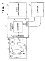
- Fig. 1 illustrates a system using a converting adapter according to the first embodiment of the present invention.
- reference numeral 1 denotes the converting adapter; 2, an interchangeable lens (to be abbreviated as a lens hereinafter) for, e.g., a single-lens reflex camera; 3, a camera (image processor), such as a video camera, a scanner camera, or a film camera, which uses the lens 2 as a scanning optical system; 30, a mount for mounting the camera 3; 4, a general-purpose computer for controlling the lens 2; 5, a mount for mounting the lens 2; 6, electrical contacts attached to the mount 5; and 7, general-purpose electrical terminals for computer communication, which perform serial communication with the computer 4.
- a lens to be abbreviated as a lens hereinafter
- an RS232C interface is used as the electrical terminals 7 in this embodiment, a centronics interface or a SCSI interface, for example, also can be used.
- a converter 8 converts a serial control signal from the computer 4 into a control signal receivable by the lens 2 or converts a signal from the lens 2 into a serial signal receivable by the computer 4.
- an internal microcomputer 2a of the single-lens reflex camera interchangeable lens 2 can be controlled by the computer 4 via an interface 2b and the converting adapter 1.
- the lens microcomputer 2a causes a controller 2d to control a lens actuator 2c, thereby driving, e.g., a focusing lens stop mechanism (to be referred to as an IRIS hereinafter) 2e.
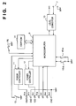
- Fig. 2 is a circuit diagram for explaining the details of the adapter 1 shown in Fig. 1.
- reference numeral 6-a denotes a power terminal (for supplying a power VBAT) which drives the internal lens actuator of the lens 2; 6-b, a ground terminal for the power terminal 6-a; 6-c, a power terminal (for supplying a power VDD) which operates an internal circuit system of the lens 2; and 6-d, a ground contact for the power contact 6-c.
- An interchangeable lens mount detection switch 13 is closed only when the lens 2 is mounted on the mount 5 and becomes controllable by the adapter 1 via the electrical signal contacts 6.
- the switch 13 is connected to the microcomputer 9.
- a nonvolatile memory 14 also is connected to the microcomputer 9, so erase, write, and read actions to data in the memory 14 are controlled by the microcomputer 9.
- the transfer rate of the RS232C interface is set as illustrated in Fig. 3 in accordance with the states of mode switches 15-a and 15-b.
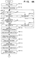
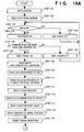
- Step 101 When the main switch PS in Fig. 2 is turned on, the microcomputer 9 initializes the memory, the I/O ports, and the like components. At the same time, the microcomputer 9 sets the transfer rate of the RS232C serial communication in accordance with the states of the switches 15.
- the data F_MEMO0 to F_MEMO7, F_SPD0 to F_SPD3, and I_SPD0 to I_SPD3 are stored in memories MF_MEMO0 to MF_MEMO7, MF_SPD0 to MF_SPD3, and MI_SPD0 to MI_SPD3 (none of the memories is shown), respectively, of the microcomputer 9.
- Step 103 The microcomputer 9 checks the state of the switch 13. If the switch 13 is ON, this indicates that the lens 2 is mounted on the adapter 1, so the flow advances to step 105. If the switch 13 is OFF, the flow advances to step 104.
- Step 105 Since the microcomputer 9 determines in step 103 that the lens 2 is mounted on the adapter 1, the microcomputer 9 so controls the power controller 12 that the power VDD is supplied to the power terminal 6-c, and the flow advances to step 106. That is, in steps 103 to 105, the power VDD is not supplied until the lens 2 is mounted and is supplied when the lens 2 is mounted.
- Step 106 Since the circuit power VDD is supplied to the lens 2 in step 105, the microcomputer 9 performs bidirectional serial communication with the microcomputer 2a in the lens 2 via the electrical contacts 6-e, 6-f, and 6-g. If this serial communication does not terminate normally, the flow advances to step 107. If the serial communication terminates normally, the flow advances to step 108.
- Step 108 Since the communication with the microcomputer 2a in the lens 2 terminates normally, the microcomputer 9 controls the power controller 11 so that the power VBAT is supplied to the power terminal 6-a, and the flow advances to step 109. In steps 106 to 108, the power VBAT is supplied only when the communication with the microcomputer 2a in the lens 2 terminates normally.
- Step 109 The microcomputer 9 controls the mounted lens 2 via the electrical contacts 6 so that the IRIS of the lens 2 is driven in the direction of a full aperture.
- Step 112 ⁇ The microcomputer 9 controls the mounted lens 2 via the electrical contacts 6 so that the value of the focus encoder (not shown) is reset to 0.
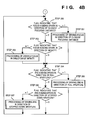
- Step 120 The microcomputer 9 analyzes the received command, and the flow advances to a corresponding command reception processing routine. Steps 130 to 135 in Fig. 5B explain the processing when a command for driving the focus in the direction of the closest focusing distance is received.
- Step 131 ⁇ If a flag indicating that the focus is being driven in the direction of the closest focusing distance is set, this means that the focus is already being driven in the direction of the closest focusing distance. Accordingly, the microcomputer 9 terminates the communication interrupt routine without performing any processing.
- Step 144 The microcomputer 9 sets the flag indicating that the focus is being driven in the direction of infinity.
- Step 145 The microcomputer 9 clears the flag indicating that the focus is being driven in the direction of the closest focusing distance, and completes the communication interrupt processing.
- Step 151 ⁇ The microcomputer 9 clears the flag indicating that the focus is being driven in the direction of the closest focusing distance.
- Step 152 The microcomputer 9 clears the flag indicating that the focus is being driven in the direction of infinity, and completes the communication interrupt routine.
- Step 155 ⁇ In accordance with the received focus speed number, the microcomputer 9 copies the speed data from the memories MF_SPD0 to MF_SPD3 into the memory P and completes the communication interrupt routine.
- Step 156 ⁇ The microcomputer 9 reads the focus encoder value from the lens 2 via the electrical contacts 6 and stores the value in the memories MF_MEMO0 to MF_MEMO7 (not shown) in accordance with the received storage number.
- the microcomputer 9 reads the focus encoder value from the lens 2 via the electrical contacts 6, stores the value in the nonvolatile memories F_MEMO0 to F_MEMO7 (not shown) in accordance with the received storage number, and completes the communication interrupt routine.
- Step 161 ⁇ The microcomputer 9 reads the focus encoder value from the lens 2 via the electrical contacts 6 and stores the value in the memory ENC_0 (not shown).
- Step 163 ⁇ The microcomputer 9 controls the mounted lens 2 via the electrical contacts 6 so that the focus of the lens 2 is driven by the driving amount P'.
- Step 164 ⁇ The microcomputer 9 clears the flag indicating that the focus is being driven in the direction of infinity.
- Step 173 ⁇ The microcomputer 9 controls the mounted lens 2 via the electrical contacts 6 so that the IRIS of the lens 2 is driven by a 1/8 step in the direction of the full aperture.
- Step 174 ⁇ The microcomputer 9 starts a timer so as to generate an interrupt after elapse of a time T.
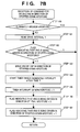
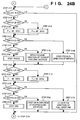
- Steps 180 to 187 in Fig. 7B explain the processing when a command for driving the IRIS in the direction of the stopped-down aperture is received.
- Step 181 ⁇ The microcomputer 9 copies data of an IRIS speed number currently being set from the memories MI_SPD0 to MI_SPD3 (not shown) into the memory T (not shown).
- Step 182 If the flag indicating that the IRIS is being driven in the direction of the stopped-down aperture is set, this means that the IRIS is already being driven in the direction of the stopped-down aperture. Accordingly, the microcomputer 9 terminates the communication interrupt routine without performing any processing.
- Step 183 ⁇ The microcomputer 9 controls the mounted lens 2 via the electrical contacts 6 so that the IRIS of the lens 2 is driven by a 1/8 step in the direction of the stopped-down aperture.
- Step 184 ⁇ The microcomputer 9 starts the timer so as to generate an interrupt after elapse of a time T.
- Step 186 The microcomputer 9 clears the flag indicating that the IRIS is being driven in the direction of the full aperture.
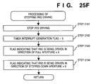
- Steps 190 to 193 in Fig. 7C explain the processing when a command for stopping IRIS driving is received.
- Step 190 ⁇ The microcomputer 9 controls the mounted lens 2 via the electrical contacts 6 so that IRIS driving of the lens 2 is stopped.
- Step 191 ⁇ The microcomputer 9 clears the timer interrupt generation flag.
- Step 192 The microcomputer 9 clears the flag indicating that the IRIS is being driven in the direction of the full aperture.
- Step 203 If the flag indicating that the focus is being driven in the direction of infinity is set, in step 203 the microcomputer 9 performs processing of driving the focus in the direction of infinity.
- Step 204 If the flag indicating that the IRIS is being driven in the direction of the full aperture is set, in step 205 the microcomputer 9 performs processing of driving the IRIS in the direction of the full aperture.
- Step 207 If the flag indicating that the IRIS is being driven in the direction of the stopped-down aperture is set, in step 207 the microcomputer 9 performs processing of driving the IRIS in the direction of the stopped-down aperture.
- Step 210 The microcomputer 9 reads the focus encoder value from the lens 2 via the electrical contacts 6 and stores the value in a memory ENC_1 (not shown).
- the microcomputer 9 controls the mounted lens 2 via the electrical contacts 6 so that the focus of the lens 2 is driven by the driving amount P in the direction of the closest focusing distance.
- Step 215 The microcomputer 9 controls the mounted lens 2 via the electrical contacts 6 so that the focus of the lens 2 is stopped.
- Step 216 The microcomputer 9 clears the flag indicating that the focus is being driven in the direction of the closest focusing distance, and completes the subroutine of driving the focus in the direction of the closest focusing distance.
- Step 220 The microcomputer 9 reads the focus encoder value from the lens 2 via the electrical contacts 6 and stores the value in the memory ENC_1 (not shown).
- Step 221 The microcomputer 9 compares the last focus encoder value ENC_0 with the current focus encoder value ENC_1. If the values are equal, the flow advances to step 224. If the values are different, the flow advances to step 222.
- Step 222 The microcomputer 9 copies the contents of the current focus encoder value ENC_1 in EMC_0, thereby updating ENC_0.
- Step 224 The microcomputer 9 reads information indicating whether the focus has reached the infinity mark from the lens 2 via the electrical contacts 6. If NO in step 224, the microcomputer 9 immediately terminates the subroutine of driving the focus in the direction of infinity. If YES in step 224, the flow advances to step 225.
- Step 225 The microcomputer 9 controls the mounted lens 2 via the electrical contacts 6 so that the focus of the lens 2 is stopped.
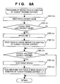
- Steps 230 to 237 in Fig. 9A represent the subroutine of driving the IRIS in the direction of the full aperture in step 205, Fig. 4B.
- Step 230 If the timer interrupt generation flag is not set, this means that the time T has not elapsed from the last IRIS driving. Accordingly, the microcomputer 9 immediately terminates the subroutine of driving the IRIS in the direction of the full aperture. If the timer interrupt generation flag is set, the flow advances to step 231.
- Step 231 The microcomputer 9 reads information indicating whether the IRIS of the mounted lens 2 is at the full aperture via the electrical contacts 6. If YES in step 231, the IRIS need not be further driven in the direction of the full aperture, so the flow advances to step 235.
- Step 233 ⁇ The microcomputer 9 starts the timer so as to generate an interrupt after elapse of a time T.
- Step 234 The microcomputer 9 clears the timer interrupt generation flag and completes the subroutine of driving the IRIS in the direction of the full aperture.
- Step 235 The microcomputer 9 controls the mounted lens 2 via the electrical contacts 6 so that the IRIS driving of the lens 2 is stopped.
- Step 236 The microcomputer 9 clears the flag indicating that the IRIS is being driven in the direction of the full aperture.
- Steps 240 to 247 in Fig. 9B represent the subroutine of driving the IRIS in the direction of the stopped-down aperture in step 207, Fig. 4B.
- Step 240 If the timer interrupt generation flag is not set, this means that the time T has not elapsed from the last IRIS driving. Accordingly, the microcomputer 9 immediately terminates the subroutine of driving the IRIS in the direction of the stopped-down aperture. If the timer interrupt generation flag is set, the flow advances to step 241.
- Step 241 The microcomputer 9 reads information indicating whether the IRIS of the mounted lens 2 is at the minimum aperture via the electrical contacts 6. If YES in step 241, the IRIS cannot be further stopped down, so the flow advances to step 245.
- Step 242 ⁇ The microcomputer 9 controls the lens 2 via the electrical contacts 6 so that the IRIS of the lens 2 is driven by a 1/8 step in the direction of the stopped-down aperture.
- Step 244 ⁇ The microcomputer 9 clears the timer interrupt generation flag and completes the subroutine of driving the IRIS in the direction of the stopped-down aperture.
- Step 245 The microcomputer 9 controls the mounted lens 2 via the electrical contacts 6 so that the IRIS driving of the lens 2 is stopped.
- Step 246 The microcomputer 9 clears the flag indicating that the IRIS is being driven in the direction of the stopped-down aperture.
- Step 250 in Fig. 9C represents the timer interrupt routine performed when a timer interrupt occurs.
- Step 250 The microcomputer 9 sets the timer interrupt generation flag for a timer interrupt after elapse of time T and completes the interrupt routine.
- a speed servo method by which the rotation of a motor to be controlled is made follow the target speed is well known as the motor control method.
- this speed servo method as illustrated in Fig. 11, as the target stop position is approached the target speed is gradually decreased to increase the stop position accuracy.
- control for the focusing actuator is in many instances so programmed as to have the characteristic as shown in Fig. 11.
- the following method is used in manual focusing in which the stop position is not predetermined. That is, in order that the focus of the lens 2 having the focus driving characteristic as in Fig. 11 can be continuously driven at a given speed, a small driving amount P is repetitively set from the converting adapter 1 into the lens 2 at each predetermined time interval, thereby controlling driving of the lens. Since a velocity V is determined by the driving amount P to the target position, if the driving amount is P1 the velocity is kept at V1. On the other hand, in cases where the focus is to be driven to a prestored focus position such as in automatic focusing, the focus is driven to the target position at once by the first driving control without performing the driving control a number of times as described above. This makes driving control within the shortest time possible.
- an RS232C interface is used as the interface between the computer 4 and the adapter 1, some other communication format also can be used.
- an auto IRIS function for controlling the IRIS by providing the converting adapter with an input terminal VIDEO IN for receiving a video signal from an external device and a level detector 16 for detecting the average level of the input video signal.
- a converting adapter according to the second embodiment of the present invention will be described below. Note that a description of parts similar to those of the first embodiment described above will be omitted. Note also that the same reference numerals as in the figures of the first embodiment denote the same parts in the figures of the second embodiment.
- Fig. 13 shows a system using the converting adapter of the second embodiment of the present invention.
- reference numeral 16 denotes a panhead which supports a lens 2 and a camera 3 via the converting adapter, 1, and also determines the direction of these parts; 16a, a motor for rotating the panhead 16; and 16b, a position detector for detecting the rotating position of the panhead 16.
- a converter 8 converts a serial control signal from a computer 4 and thereby controls the lens 2 or the panhead 16. The rest of the arrangement is identical with that shown in Fig. 1, and the data transfer rate on the interface is the same as in Fig. 3.
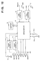
- the lens microcomputer 2a controls a lens actuator 2c via a controller 2d, thereby driving, e.g., a focusing lens 2f and a diaphragm 2e.
- Fig. 14 is a circuit diagram for explaining the details of the adapter 1 in Fig. 13.
- a motor driver 17 supplies a signal for driving the motor 16a of the panhead 16.
- Electrical contacts 18 are connected to the panhead 16 attached to the adapter 1. The rest of the arrangement is identical with that shown in Fig. 2.
- Figs. 15A and 15B are flow charts for explaining the operation of a microcomputer 9. Individual steps of the flow charts in Figs. 15A and 15B will be described below.
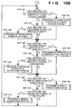
- Step 1101 When a main switch PS, Fig. 14, is turned on, the microcomputer 9 initializes the memories, the I/O ports, and the like components. At the same time, the microcomputer 9 sets the transfer rate of RS232C serial communication in accordance with the states of switches 15.
- the microcomputer 9 reads out the contents of a nonvolatile memory 14 and stores them in internal memories of the microcomputer 9. Note that data having the contents shown in Fig. 18 is stored in the nonvolatile memory 14. Referring to Fig.
- F_MEMO0 to F_MEMO7 are focus position storage data which are set in a one-to-one correspondence with focus encoder values in the lens 2; U_MEMO0 to U_MEMO7 are panhead position storage data which are set in a one-to-one correspondence with output values from the position detector 16b; F_SPD0 to F_SPD3 are focus speed data which are set in a one-to-one correspondence with focus driving amounts in the lens 2; I_SPD0 to I_SPD3 are IRIS speed data which are set in a one-to-one correspondence with time intervals during which the diaphragm (IRIS) in the lens 2 is driven; and U_SPD0 to U_SPD3 are panhead speed data which are set in a one-to-one correspondence with the values of a voltage applied to the motor 16a.
- the data F_MEMO0 to F_MEMO7, U_MEMO0 to U_MEMO7, F_SPD0 to F_SPD3, I_SPD0 to I_SPD3, and U_SPD0 to U_SPD3 are stored in memories MF_MEMO0 to MF_MEMO7, MU_MEMO0 to MU_MEMO7, MF_SPD0 to MF_SPD3, MI_SPD0 to MI_SPD3, and MU_SPD0 to MU_SPD3 (neither of the memories is shown), respectively, of the microcomputer 9.
- Step 1103 The microcomputer 9 checks the state of a switch 13. If the switch 13 is ON, this means that the lens 2 is mounted, so the flow advances to step 1105. If the switch 13 is OFF, the flow advances to step 1104.
- Step 1104 Since the microprocessor 9 determines in step 1103 that the lens 2 is not mounted on the adapter 1, the microprocessor 9 so controls a power controller 12 that a power VDD is not supplied to a power terminal 6-c, and the flow returns to step 1103.
- Step 1105 Since the microcomputer 9 determines in step 1103 that the lens 2 is mounted on the adapter 1, the microcomputer 9 so controls the power controller 12 that the power VDD is supplied to the power terminal 6-c, and the flow advances to step 1106. That is, in steps 1103 to 1105, the power VDD is not supplied while the lens 2 is mounted and is supplied when the lens 2 is mounted.
- Step 1106 Since the circuit power VDD is supplied to the lens 2 in step 1105, the microcomputer 9 performs bidirectional serial communication with the microcomputer 2a in the lens 2 via electrical contacts 6-e, 6-f, and 6-g. If this serial communication does not terminate normally, the flow advances to step 1107. If the serial communication terminates normally, the flow advances to step 1108.
- Step 1108 Since the communication with the microcomputer 2a in the lens 2 terminates normally, the microcomputer 9 controls the power controller 11 so that the power VBAT is supplied to the power terminal 6-a, and the flow advances to step 1109. In steps 1106 to 1108, the power VBAT is supplied only when the communication with the microcomputer 2a in the lens 2 terminates normally.
- the microcomputer 9 controls the mounted lens 2 via the electrical contacts 6 so that the IRIS of the lens 2 is driven in the direction of a full aperture.
- the microcomputer 9 reads information pertaining to the IRIS of the mounted lens 2, such as the full-aperture f-number and the minimum-aperture f-number, via the electrical contacts 6, and stores the information in memories AV_O and AV_MAX (not shown), respectively.
- Step 1111 ⁇ The microcomputer 9 controls the mounted lens 2 via the electrical contacts 6 so that the focus of the lens 2 is driven in the direction of a closest focusing distance.
- Step 1112 The microcomputer 9 controls the mounted lens 2 via the electrical contacts 6 so that the focus encoder value is reset to 0.
- the microcomputer 9 controls the mounted lens 2 via the electrical contacts 6 so that the focus of the lens 2 is driven in the direction of infinity.
- the microcomputer 9 reads the focus encoder value of the mounted lens 2 via the electrical contacts 6 and stores the value in a memory ENC_MAX (not shown).
- Step 1115 The microcomputer 9 controls the motor driver 17 while monitoring the output from the position detector 16b so that the panhead is driven to the initial position.
- the microcomputer 9 drives the IRIS, the focus, and the panhead of the mounted lens 2 to their respective initial positions. Also, the microcomputer 9 reads, from the lens 2, the full-aperture f-number and the minimum-aperture f-number, as inherent data of the lens, and the focus encoder value at the infinity mark assuming the value at the closest focusing distance is 0, and stores these data in the memories, thereby reading the characteristics of the lens.
- Step 1116 The microcomputer 9 permits a communication via the RS232C interface. If a communication is received, the microcomputer 9 permits an interrupt to occur, and the flow advances to step 1300.
- the contents of the interrupt processing when the RS232C communication is received, the processing when a command for driving the focus in the direction of the closest focusing distance is received, the processing when a command for driving the focus in the direction of infinity is received, the processing when a command for stopping the focus is received, and the processing when a command for setting the focus speed is received, are identical with the contents in the first embodiment and those shown in Figs. 5A to 5E.
- the contents of the processing when a command for storing the focus position is received and the processing when a command for driving the focus to the stored position is received are identical with the contents in the first embodiment and those shown in Figs. 6A and 6B.
- the contents of the processing when a command for driving the IRIS in the direction of the full aperture is received, the processing when a command for driving the IRIS in the direction of the stopped-down aperture is received, and the processing when a command for stopping the IRIS driving is received are identical with the contents in the first embodiment and those shown in Figs. 7A to 7D.
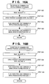
- Steps 1200 to 1203 in Fig. 16A explain the processing when a command for rotating the panhead clockwise is received.
- Step 1200 The microcomputer 9 copies data of a currently set panhead speed number from the memories MU_SPD0 to MU_SPD3 (not shown) into a memory V (not shown).
- Step 1201 The microcomputer 9 so controls the motor driver 17 that the panhead is rotated clockwise (in a direction CW) with a voltage V.
- Step 1203 The microcomputer 9 clears a flag indicating that the panhead is being rotated counterclockwise (in a direction CCW), and completes the communication interrupt routine.
- Steps 1205 to 1208 in Fig. 16B explain the processing when a command for rotating the panhead counterclockwise is received.
- Step 1206 The microcomputer 9 so controls the motor driver 17 that the panhead is rotated counterclockwise (in the direction CCW) with the voltage V.
- Step 1207 ⁇ The microcomputer 9 clears the flag indicating that the panhead is being driven in the direction CW.
- Step 1208 The microcomputer 9 sets the flag indicating that the panhead is being driven in the direction CCW, and completes the communication interrupt routine.
- Steps 1210 to 1212 in Fig. 16C explain the processing when a command for stopping the rotation of the panhead is received.
- Step 1210 The microcomputer 9 so controls the motor driver 17 that the rotation of the panhead is stopped.
- Step 1211 ⁇ The microcomputer 9 clears the flag indicating that the panhead is being driven in the direction CW.
- Step 1215 in Fig. 16D explains the processing when a command for setting the driving speed of the panhead is received.
- Steps 1220 and 1221 in Fig. 16E explain the processing when a command for storing the panhead position is received.
- Step 1221 ⁇ The microcomputer 9 reads current position data from the position detector 16b, stores the data in the nonvolatile memories U_MEMO0 to U_MEMO7 in accordance with the received storage number, and completes the communication interrupt routine.
- Steps 1225 to 1230 in Fig. 16F explain the processing when a command for driving the panhead to the stored position is received.
- the microcomputer 9 stores the data from the memories MU_MEMO0 to MU_MEMO7 into a memory ENC_U (not shown) That is, the data stored in ENC_U2 indicates the target position to which the panhead is to be driven.
- Step 1228 ⁇ The microcomputer 9 so controls the motor driver 17 as to rotate the panhead by the driving amount L.
- Step 1229 The microcomputer 9 clears the flag indicating that the panhead is being driven in the direction CW.
- Step 1230 The microcomputer 9 clears the flag indicating that the panhead is being driven in the direction CCW, and completes the communication interrupt routine.
- step 1116 the microcomputer 9 must receive various commands and cause the lens 2 to perform the respective corresponding operations of the received commands, since the microcomputer 9 permits the RS232C communication in step 1116.
- steps 1300 to 1307 the microcomputer 9 checks whether focus driving or IRIS driving needs to be performed, and executes each corresponding processing.
- Step 1301 If a flag indicating that the focus is being driven in the direction of the closest focusing distance is set, in step 1301 the microcomputer 9 performs processing of driving the focus in the direction of the closest focusing distance.
- Step 1302 ⁇ If a flag indicating that the focus is being driven in the direction of infinity is set, in step 1303 the microcomputer 9 performs processing of driving the focus in the direction of infinity.
- Step 1305 If a flag indicating that the IRIS is being driven in the direction of the full aperture is set, in step 1305 the microcomputer 9 performs processing of driving the IRIS in the direction of the full aperture.
- Step 1306 If the flag indicating that the IRIS is being driven in the direction of a stopped-down aperture is set, in step 1307 the microcomputer 9 performs processing of driving in the direction of the stopped-down aperture.
- Step 1308 If the flag indicating that the panhead is being driven in the direction CW is set, in step 1309 the microcomputer 9 performs processing of rotating the panhead clockwise.
- Step 1310 If the flag indicating that the panhead is being driven in the direction CCW is set, in step 1311 the microcomputer 9 performs processing of rotating the panhead counterclockwise.
- the processing of driving the focus in the direction of the closest focusing distance and the processing of driving the focus in the direction of infinity are the same as in the first embodiment and in Figs. 8A and 8B.
- processing of driving the IRIS in the direction of the full aperture the processing of driving the IRIS in the direction of the stopped-down aperture, and the timer interrupt processing are the same as in the first embodiment and in Figs. 9A to 9C.
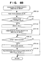
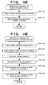
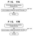
- Step 1360 in Fig. 17A represents the subroutine of driving the panhead clockwise in step 1309, Fig. 15B.
- Step 1370 in Fig. 17B represents the subroutine of rotating the panhead counterclockwise in step 1311, Fig. 15B.
- Step 1370 The microcomputer 9 so controls the motor driver 17 that the panhead is rotated counterclockwise with the voltage V, and completes the subroutine.
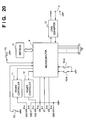
- Fig. 20 The difference of Fig. 20 from Fig. 14 is that the electrical terminals 19 are provided instead of the electrical contacts 17 and 18.
- Figs. 4A -4B and Figs. 21A - 21B are flow charts for explaining the operation of the microcomputer 9, Fig. 20.
- the flow of the operations in Figs. 4A and 4B are the same as that in the first embodiment, and so a detailed description thereof will be omitted.
- Step 1496 in Fig. 21A explains the processing when a command for outputting data to an external peripheral circuit is received.
- Step 1496 The microcomputer 9 outputs the received data to the external circuit 20 via the electrical contacts 19 and completes the interrupt routine.
- Steps 1497 and 1498 in Fig. 21B explain the processing when a command for inputting data from the external peripheral circuit is received.
- Step 1497 The microcomputer 9 reads data from the external peripheral circuit 20 via the electrical contacts 19.
- a converting adapter according to the third embodiment of the present invention will be described below. Note that a description of parts similar to those of the first and second embodiments described above will be omitted. Note also that the same reference numerals as in the figures of the first and second embodiments denote the same parts in the figures of the third embodiment.
- the circuit configuration of the adapter 1 of this embodiment is identical with that shown in Fig. 20, and the data transfer rate of the interface is the same as in Fig. 3.
- signals are converted by using software, instead of using the converters 8a and 8b in Fig. 1, in a microcomputer 9.
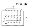
- Fig. 23 is a view for explaining a practical example of the external control device 32 according to this embodiment.
- the external control device 32 is, for example, a manual remote control unit.
- the switch 20 is used to drive the focus in the direction of infinity. While the switch 20 is ON the focus is driven in the direction of infinity.
- the switch 21 is used to drive the focus in the direction of a closest focusing distance. While the switch 21 is ON the focus is driven in the direction of the closest focusing distance.
- the switch 23 is used to drive the diaphragm in the direction of a stopped-down aperture; while the switch 23 is ON the diaphragm is driven in the direction of the stopped-down aperture.
- the switch 24 is used to switch the focus speeds; the focus speed is high when the switch 24 is ON and is low when the switch 24 is OFF.
- the switch 25 is used to switch the IRIS speeds; the IRIS speed is high when the switch 25 is ON and is low when the switch 25 is OFF.
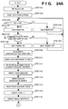
- Figs. 24A and 24B are flow charts for explaining the operation of a microcomputer 9. Individual steps of the flow charts in Figs. 24A and 24B will be described below.
- Step 2101 When a main switch PS, Fig. 20, is turned on, the microcomputer 9 initializes the memories, the I/O ports, and the like components. At the same time, the microcomputer 9 sets the transfer rate of RS232C serial communication in accordance with the states of the switches 20 to 25.
- the microcomputer 9 reads out the contents of a nonvolatile memory 14 and stores them in internal memories (RAMs) of the microcomputer 9. Note that data having the contents shown in Fig. 10 is stored in the nonvolatile memory 14. Referring to Fig.
- Step 2104 Since the microprocessor 9 determines in step 2103 that the lens 2 is not mounted on the adapter 1, the microprocessor 9 so controls a power controller 12 that a power VDD is not supplied to a power terminal 6-c, and the flow returns to step 2103.
- Step 2105 Since the microcomputer 9 determines in step 2103 that the lens 2 is mounted on the adapter 1, the microcomputer 9 so controls the power controller 12 that the power VDD is supplied to the power terminal 6-c, and the flow advances to step 2106. That is, in steps 2103 to 2105, the power VDD is not supplied while the lens 2 is mounted and is supplied when the lens 2 is mounted.
- Step 2107 Since the communication with the microcomputer 2a in the lens 2 terminates abnormally, the microcomputer 9 controls a power controller 11 so that a power VBAT is not supplied to a power terminal 6-a, and the flow returns to step 2103.
- Step 2108 Since the communication with the microcomputer 2a in the lens 2 terminates normally, the microcomputer 9 controls the power controller 11 so that the power VBAT is supplied to the power terminal 6-a, and the flow advances to step 2109. In steps 2106 to 2108, the power VBAT is supplied only when the communication with the microcomputer 2a in the lens 2 terminates normally.
- the microcomputer 9 reads information indicating the full-aperture f-number and the minimum-aperture f-number of the mounted lens 2 via the electrical terminals 6, and stores the information in memories AV_O and AV_MAX (not shown), respectively.
- Step 2111 ⁇ The microcomputer 9 controls the mounted lens 2 via the electrical terminals 6 so that the focus of the lens 2 is driven in the direction of the closest focusing distance.
- Step 2112 The microcomputer 9 controls the mounted lens 2 via the electrical terminals 6 so that the value of a focus encoder (not shown) is reset to 0.
- the microcomputer 9 reads the focus encoder value of the mounted lens 2 via the electrical terminals 6 and stores the value in a memory ENC_MAX (not shown).
- the microcomputer 9 drives the IRIS and the focus of the mounted lens 2 to their respective initial positions. Also, the microcomputer 9 reads, from the lens 2, the full-aperture f-number and the minimum-aperture f-number, as inherent data of the lens, and the focus encoder value at the infinity mark assuming the value at the closest focusing distance is 0, and stores these data in the memories, thereby reading the characteristics of the lens.
- Step 2115 The microcomputer 9 sets a SELECT flag to permit control from the external control device 32.
- Step 2116 The microcomputer 9 permits an interrupt which occurs when a communication done through the RS232C interface is received. If an interrupt occurs, the flow advances to an RS232C communication interrupt routine starting from step 2200 in Fig. 26A.
- Step 2117 If the SELECT flag is set, this means that control from the external control device 32 is effective, and so the flow advances to step 2118. If the SELECT flag is cleared, the flow advances to step 2130 in Fig. 28 to inhibit control from the external control device 32.
- Step 2118 The microcomputer 9 detects the state of the switch 24, Fig. 23, for switching the focus speeds. If the switch 24 is ON, the flow advances to step 2119. If the switch 24 is OFF, the flow advances to step 2120.
- Step 2119 In accordance with the determination result in step 2118, the microcomputer 9 performs high-speed focus driving. For this purpose, the microcomputer 9 copies the focus speed data set in the memory MF_SPD3 (not shown) into a memory P (not shown), and the flow advances to step 2121.
- Step 2120 Since the microcomputer 9 determines in step 2118 that low-speed focus driving is to be performed, the microcomputer 9 copies the focus speed data set in the memory MF_SPD0 (not shown) into the memory P (not shown), and the flow advances to step 2121. Note that the contents in the memories MF_SPD0 and MF_SPD3 satisfy MF_SPD0 ⁇ MF_SPD3.
- Step 2121 The microcomputer 9 detects the state of the switch 20. If the switch 20 is ON, the microcomputer 9 drives the focus in the direction of infinity. For this purpose, in step 2140 the microcomputer 9 executes a subroutine of driving the focus in the direction of infinity, and the flow advances to step 2123.
- Step 2122 The microcomputer 9 detects the state of the switch 21. If the switch 21 is ON, the microcomputer 9 drives the focus in the direction of the closest focusing distance. For this purpose, in step 2150 the microcomputer 9 executes a subroutine of driving the focus in the direction of the closest focusing distance, and the flow advances to step 2123. If the switch 21 is OFF, in step 2160 the microcomputer 9 executes a subroutine of stopping the focus, and the flow advances to step 2123.
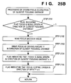
- Step 2123 The microcomputer 9 detects the state of the switch 25 for switching the IRIS speeds. If the switch 25 is ON, the flow advances to step 2124. If the switch 25 is OFF, the flow advances to step 2125.
- Step 2124 The microcomputer 9 determines in step 2123 that high-speed IRIS driving is to be performed. For this purpose, the microcomputer 9 copies the IRIS speed data set in the memory MI_SPD3 (not shown) into a memory T (not shown), and the flow advances to step 2126.
- Step 2126 The microcomputer 9 detects the state of the switch 22. If the switch 22 is ON, the microcomputer 9 drives the IRIS in the direction of the full aperture. For this purpose, in step 2170 the microcomputer 9 executes a subroutine of driving the IRIS in the direction of the full aperture, and the flow advances to step 2130.
- Step 2127 The microcomputer 9 detects the state of the switch 23. If the switch 23 is ON, the microcomputer 9 drives the IRIS in the direction of the stopped-down aperture. For this purpose, in step 2180 the microcomputer 9 executes a subroutine of driving the IRIS in the direction of the stopped-down aperture, and the flow advances to step 2130. If the switch 23 is OFF, in step 2190 the microcomputer 9 executes a subroutine of stopping the focus, and the flow advances to step 2130.
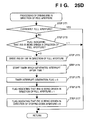
- Step 2141 ⁇ If a flag indicating that the focus is being driven in the direction of infinity is set, this means that the focus is already being driven in the direction of infinity. Accordingly, the microcomputer 9 terminates the subroutine without performing any processing.
- Step 2142 The microcomputer 9 reads a focus encoder value immediately before the focus is driven via the electrical terminals 6 and stores the value in a memory ENC_0 (not shown).
- Step 2144 The microcomputer 9 sets the flag indicating that the focus is being driven in the direction of infinity.
- Step 2145 The microcomputer 9 clears a flag indicating that the focus is being driven in the direction of the closest focusing distance, and completes the subroutine.
- Step 2151 If the flag indicating that the focus is being driven in the direction of the closest focusing distance is set, this means that the focus is already being driven in the direction of the closest focusing distance. Accordingly, the microcomputer 9 terminates the subroutine without performing any processing.
- Step 2152 ⁇ The microcomputer 9 reads a focus encoder value immediately before the focus is driven via the electrical terminals 6 and stores the value in the memory ENC_0 (not shown).
- Step 2154 The microcomputer 9 sets the flag indicating that the focus is being driven in the direction of the closest focusing distance.
- Step 2155 The microcomputer 9 clears the flag indicating that the focus is being driven in the direction of infinity, and completes the subroutine.
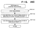
- the microcomputer 9 controls the mounted lens 2 via the electrical terminals 6 so that the focus of the lens 2 is stopped.
- Step 2162 ⁇ The microcomputer 9 clears the flag indicating that the focus is being driven in the direction of the closest focusing distance.
- Step 2163 The microcomputer 9 clears the flag indicating that the focus is being driven in the direction of infinity, and completes the subroutine.
- the microcomputer 9 controls the mounted lens 2 via the electrical terminals 6 so that the IRIS of the lens 2 is driven by a 1/8 step in the direction of the full aperture.
- Step 2174 ⁇ The microcomputer 9 starts a timer so as to generate an interrupt after elapse of a time T.
- Step 2175 ⁇ The microcomputer 9 clears a timer interrupt generation flag.
- Step 2176 The microcomputer 9 sets the flag indicating that the IRIS is being driven in the direction of the full aperture.
- Step 2177 The microcomputer 9 clears a flag indicating that the IRIS is being driven in the direction of the stopped-down aperture, and completes the subroutine.
- Step 2181 The microcomputer 9 reads information indicating whether the IRIS is currently at the minimum aperture from the lens 2 via the electrical terminals. If YES in step 2181, the IRIS cannot be further driven in the direction of the stopped-down aperture, so the microcomputer 9 immediately terminates the subroutine. If NO in step 2181, the flow advances to step 2182.
- Step 2182 If a flag indicating that the IRIS is being driven in the direction of the stopped-down aperture is set, this means that the IRIS is already being driven in the direction of the stopped-down aperture. Accordingly, the microcomputer 9 terminates the subroutine without performing any processing.
- Step 2184 ⁇ The microcomputer 9 starts the timer so as to generate an interrupt after elapse of a time T.
- Step 2191 ⁇ The microcomputer 9 controls the mounted lens 2 via the electrical terminals 6 so that IRIS driving of the lens 2 is stopped.
- Step 2193 The microcomputer 9 clears the flag indicating that the IRIS is being driven in the direction of the full aperture.
- the microcomputer 9 drives and stops the focus and the IRIS on the basis of the signals from the external control device 32, i.e., in this embodiment the signals corresponding to the states of the switches.
- the control routines only for the focus and the IRIS have been described above.
- it is also possible to perform these control routines from an external control device by providing, in a lens, a zoom actuator or some other optical actuator, e.g., an optical means for optically compensating for a camera shake or an optical means for obtaining a high resolution by optically shifting an image.
- the microcomputer 9 clears the SELECT flag to inhibit control from the external control device 32. That is, the microcomputer 9 allows only control from an external computer via the RS232C interface.
- Step 2201 The microcomputer 9 analyzes the received command, and the flow advances to a corresponding command reception processing routine.
- the processing when a command for driving the focus in the direction of the closest focusing distance is received, the processing when a command for driving the focus in the direction of infinity is received, the processing when a command for stopping the focus driving is received, and the processing when a command for setting the focus driving speed is received are identical with those shown in Figs. 5A to 5E described previously.
- the processing when a command for storing the focus position is received and the processing when a command for driving the focus to the stored position is received are identical with those shown in Figs. 6A and 6B described previously.
- Step 2295 in Fig. 27 allows the external control device 32 to control the lens 2.
- Step 2295 The microcomputer 9 sets the SELECT flag to permit control from the external control device 32 until the next control through the RS232C interface, and completes the communication interrupt routine.
- Fig. 28 is a flow chart representing processing of making the lens 2 perform various operations in accordance with control signals from the external control device 32 or commands from the computer 4 via the RS232C interface.
- the microcomputer 9 determines whether the focus or the IRIS is to be driven, and performs each corresponding processing.
- Step 2130 If the flag indicating that the focus is being driven in the direction of infinity is set, in step 2300 the microcomputer 9 performs processing of driving the focus in the direction of infinity, and the flow advances to step 2132.
- Step 2131 If the flag indicating that the focus is being driven in the direction of the closest focusing distance is set, in step 2310 the microcomputer 9 performs processing of driving the focus in the direction of the closest focusing distance, and the flow advances to step 2132.
- Step 2132 If the flag indicating that the IRIS is being driven in the direction of the full aperture is set, in step 2320 the microcomputer 9 performs processing of driving the IRIS in the direction of the full aperture, and the flow returns to step 2117.
- Step 2133 If the flag indicating that the IRIS is being driven in the direction of the stopped-down aperture is set, in step 2330 the microcomputer 9 performs processing of driving the IRIS in the direction of the stopped-down aperture, and the flow returns to step 2117.
- the processing of driving the focus in the direction of the closest focusing distance and the processing of driving the focus in the direction of infinity are the same as in Figs. 8A and 8B described earlier.
- processing of driving the IRIS in the direction of the full aperture the processing of driving the IRIS in the direction of the stopped-down aperture, and the timer interrupt processing are the same as in Figs. 9A to 9C described earlier.
- the lens 2 immediately after the main switch PS is turned on the lens 2 can be controlled by both the control signals from the external control device 32 and the computer 4 via the RS232C interface. However, once the control from the computer 4 via the RS232C interface is executed, the control from the external control device 32 is inhibited until a specific command from the computer is received.
- Fig. 29 is a circuit diagram for explaining an adapter 1 and an external control device 32 as a modification of this embodiment.
- the same reference numerals as in each of the above embodiments denote the same parts in Fig. 29, and a detailed description thereof will be omitted.
- control from a computer 4 through an RS232C interface is chosen when a switch 26 is ON, and control from the external control device 32 is chosen when the switch 26 is OFF.
- Figs. 30A and 30B are flow charts for explaining the operation of a microcomputer 9 in this modification.
- the same step numbers as in the flow charts of Figs. 24A and 24B denote the same steps in Figs. 30A and 30B, and a description of the contents thereof will be omitted.
- Step 2415 The microcomputer 9 reads the state of the switch 26, Fig. 29. If the switch 26 is ON, the flow advances to step 2416. If the switch 26 is OFF, the flow advances to step 2118.
- Step 2416 The microcomputer 9 permits an interrupt which occurs when a communication via the RS232C interface is received, and the flow advances to step 2130.
- the subsequent steps until step 2133 and steps 2300, 2310, 2320, and 2330 are the same as in Fig. 28. If an interrupt occurs, the flow advances to an RS232C communication interrupt routine starting from step 2500 in Fig. 31.
- Step 2500 in Fig. 31 explains the interrupt resulting from reception of the RS232C communication.
- Step 2500 The microcomputer 9 analyzes the received command, and the flow advances to a corresponding one Of the command reception processing routines described previously.
- Fig. 32A and 32B are flow charts for explaining the operation of a microcomputer 9 in this modification.
- the same step numbers as in Fig. 24A and 24B denote the same steps in Figs. 32A and 32B, and a detailed description thereof will be omitted.
- step 2102 the microcomputer 9 reads out the contents of a nonvolatile memory 14 and stores them in internal memories of the microcomputer 9.
- data having the contents shown in Fig. 33 is stored in the nonvolatile memory 14.
- F_MEMO0 to F_MEMO7 are focus position storage data set by values from an internal focus encoder (not shown) of a lens 2
- F_SPD0 to F_SPD3 are focus speed data set by focus driving amounts in the lens 2
- I_SPD0 to I_SPD3 are IRIS speed data set by time intervals during which a diaphragm (IRIS) in the lens 2 is driven.
- Step 2615 If the contents of the memory M_MODE are 00H, the flow advances to step 2416. If the contents are FFH, the flow advances to step 2118.
- the interrupt processing routine when the RS232C communication is received is similar to the subroutine described previously, so a description thereof will be omitted.
Abstract
Description
- The present invention relates to a converting adapter for interchangeable lens assemblies of optical devices.
- Automatization of production installations has advanced in the manufacturing sites in various industries, and accordingly a large number of image formation apparatuses are used in the individual manufacturing steps such as the assembly step and the quality control step.
- On the other hand, with the recent progress of technologies, sensors having a higher resolution than that of conventional sensors have been developed. These sensors are becoming used in the manufacturing sites, and so camera lenses of, e.g., a 35-mm format whose scanning area is larger than that of C-mount lenses are beginning to be used extensively. However, these 35-mm camera lenses have a mount different in the standards from that of the C-mount lenses. Accordingly, it is necessary to connect the 35-mm camera lenses to the image formation apparatuses described above via an adapter for converting the mount.
- Unfortunately, the recent camera systems of, e.g., a 35-mm format have poor interchangeability because they are equipped with many electronic functions such as an automatic focusing function. If a lens is used in different camera systems, therefore, it is in many instances impossible to fully utilize the performance of the lens. For example, if a control operation such as focusing control or aperture control of a lens is done by using only an electrical signal, rather than by a mechanical manipulation from the outside of an image formation apparatus or a camera, a manual operation itself is difficult to perform.
- The present invention has been made in consideration of the above situation and has as a concern to provide a converting adapter for an interchangeable lens assembly, which controls an interchangeable lens assembly controlled only by an electrical signal in a control system different from a system which the interchangeable lens assembly belongs to.
- According to one aspect of the present invention a converting adapter for an interchangeable lens assembly comprises
a first mount for mounting an interchangeable lens assembly,
a second mount for mounting an optical device which uses the interchangeable lens assembly mounted on the first mount as a scanning optical system,
a first terminal provided in the first mount to exchange an electrical signal with the interchangeable lens assembly,
a second terminal connected to an external control device to exchange an electrical signal with the external control device, and
signal converting means for outputting a predetermined lens control signal to the first terminal in accordance with an input electrical signal from the second terminal,
wherein the signal converting means controls driving of a lens of the interchangeable lens assembly. - More preferably, in order to control the lens at a speed within a predetermined speed range, the signal converting means outputs an electrical signal, as a control amount corresponding to the speed, to the interchangeable lens assembly at each predetermined control period.
- Also, the converting adapter further may comprise lens characteristic detecting means for detecting a characteristic of the interchangeable lens assembly mounted on the first mount by causing the interchangeable lens assembly to perform a predetermined operation.
- A converting adapter for an interchangeable lens assembly comprises
a first mount for mounting an interchangeable lens assembly,
a second mount for mounting an optical device which uses the interchangeable lens assembly mounted on the first mount as a scanning optical system,
a first terminal provided in the first mount to exchange an electrical signal with the interchangeable lens assembly,
a second terminal connected to a first external control device to exchange an electrical signal with the first external control device,
a third terminal connected to a second external control device to exchange an electrical signal with the second external control device,
first signal converting means for outputting a predetermined lens control signal to the first terminal in accordance with an input electrical signal from the second terminal, and
second signal converting means for outputting a predetermined lens control signal to the first terminal in accordance with an input electrical signal from the third terminal. - More preferably, the converting adapter further comprises signal selecting means for selecting one or both of the first and second signal converting means.
- A converting adapter for an interchangeable lens assembly comprises
a first mount for mounting an interchangeable lens assembly,
a second mount for mounting an optical device which uses the interchangeable lens assembly mounted on the first mount as a scanning optical system,
a first terminal provided in the first mount to exchange an electrical signal with the interchangeable lens assembly,
a second terminal connected to an external control device to exchange an electrical signal with the external control device,
a third terminal connected to an external device to exchange an electrical signal with the external device,
first signal converting means for outputting a predetermined lens control signal to the first terminal in accordance with an input electrical signal from the second terminal, and
second signal converting means for outputting a predetermined external device control signal to the third terminal in accordance with an input electrical signal from the second terminal. - More preferably, a converting adapter for an interchangeable lens assembly comprises
a first mount for mounting an interchangeable lens assembly,
a second mount for mounting an optical device which uses the interchangeable lens assembly mounted on the first mount as a scanning optical system,
a first terminal provided in the first mount to exchange an electrical signal with the interchangeable lens assembly,
a second terminal connected to an external control device to exchange an electrical signal with the external control device,
a third terminal connected to an external device to exchange an electrical signal with the external device,
first signal converting means for outputting a predetermined lens control signal to the first terminal in accordance with an input electrical signal from the second terminal,
second signal converting means for outputting a predetermined external device control signal to the third terminal in accordance with an input electrical signal from the second terminal, and
signal selecting means for selecting one of the first and second signal converting means. - Moreover, as the characteristic feature of the outer appearance of each converting adapter of the present invention,
the first terminal is provided on the same side surface as the first mount, and
the second terminal is provided on the same side surface as the second mount. - Other features and advantages of the present invention will be apparent from the following description taken in conjunction with the accompanying drawings, in which like reference characters designate the same or similar parts throughout the figures thereof.
-
- Fig. 1 is a block diagram showing the system configuration of a converting adapter according to the first embodiment of the present invention;
- Fig. 2 is a circuit diagram showing the circuit configuration of the converting adapter according to the first embodiment of the present invention;
- Fig. 3 is a view showing the relationship between a
switch 15 and the baud rate of an RS232C in the first embodiment of the present invention; - Figs. 4A and 4B are main flow charts showing the operation of the converting adapter according to the first embodiment of the present invention;
- Figs. 5A to 5E are flow charts showing the operation of the converting adapter according to the first embodiment of the present invention;
- Figs. 6A and 6B are flow charts showing the operation of the converting adapter according to the first embodiment of the present invention;
- Figs. 7A to 7D are flow charts showing the operation of the converting adapter according to the first embodiment of the present invention;
- Figs. 8A and 8B are flow charts showing the operation of the converting adapter according to the first embodiment of the present invention;
- Figs. 9A to 9C are flow charts showing the operation of the converting adapter according to the first embodiment of the present invention;
- Fig. 10 is a view showing data stored in a nonvolatile memory in the first embodiment of the present invention;
- Fig. 11 is a graph showing the driving characteristic of an interchangeable lens assembly in the first embodiment of the present invention;
- Fig. 12 is a circuit diagram showing a circuit configuration added with an automatic IRIS function as a modification of the first embodiment of the present invention;
- Fig. 13 is a block diagram showing the system configuration of a converting adapter according to the second embodiment of the present invention;
- Fig. 14 is a circuit diagram showing the circuit configuration of the converting adapter according to the second embodiment of the present invention;
- Figs. 15A and 15B are main flow charts showing the operation of the converting adapter according to the second embodiment of the present invention;
- Figs. 16A to 16F are flow charts showing the operation of the converting adapter according to the second embodiment of the present invention;
- Figs. 17A and 17B are flow charts showing the operation of the converting adapter according to the second embodiment of the present invention;
- Fig. 18 is a view showing data stored in a nonvolatile memory in the second embodiment of the present invention;
- Fig. 19 is a block diagram showing the system configuration of a converting adapter as a modification of the second embodiment of the present invention;
- Fig. 20 is a circuit diagram showing the circuit configuration of the converting adapter as a modification of the second embodiment of the present invention;
- Figs. 21A and 21B are flow charts showing the operation of the converting adapter in the modification of the second embodiment of the present invention;
- Fig. 22 is a block diagram showing the system configuration of a converting adapter according to the third embodiment of the present invention;
- Fig. 23 is a circuit diagram showing the configuration of an external control device in the third embodiment of the present invention;
- Figs. 24A and 24B are main flow charts showing the operation of the converting adapter according to the third embodiment of the present invention;
- Figs. 25A to 25F are flow charts showing the operation of the converting adapter according to the third embodiment of the present invention;
- Fig. 26 is a flow chart showing the operation of the converting adapter according to the third embodiment of the present invention;
- Fig. 27 is a flow chart showing the operation of the converting adapter according to the third embodiment of the present invention;
- Fig. 28 is a flow chart showing the operation of the converting adapter according to the third embodiment of the present invention;
- Fig. 29 is a circuit diagram showing the circuit configuration of a converting adapter as the first modification of the third embodiment of the present invention;
- Figs. 30A and 30B are main flow charts showing the operation of the converting adapter as the first modification of the third embodiment of the present invention;
- Fig. 31 is a flow chart showing the operation of the converting adapter as the first modification of the third embodiment of the present invention;
- Figs. 32A and 32B are main flow charts showing the operation of a converting adapter as the second modification of the third embodiment of the present invention; and
- Fig. 33 is a view showing data stored in a nonvolatile memory in the second modification of the third embodiment of the present invention.
- Preferred embodiments of the present invention will be described in detail below with reference to the accompanying drawings.
- Fig. 1 illustrates a system using a converting adapter according to the first embodiment of the present invention. In Fig. 1,
reference numeral 1 denotes the converting adapter; 2, an interchangeable lens (to be abbreviated as a lens hereinafter) for, e.g., a single-lens reflex camera; 3, a camera (image processor), such as a video camera, a scanner camera, or a film camera, which uses thelens 2 as a scanning optical system; 30, a mount for mounting thecamera 3; 4, a general-purpose computer for controlling thelens 2; 5, a mount for mounting thelens 2; 6, electrical contacts attached to themount 5; and 7, general-purpose electrical terminals for computer communication, which perform serial communication with thecomputer 4. Although an RS232C interface is used as theelectrical terminals 7 in this embodiment, a centronics interface or a SCSI interface, for example, also can be used. Aconverter 8 converts a serial control signal from thecomputer 4 into a control signal receivable by thelens 2 or converts a signal from thelens 2 into a serial signal receivable by thecomputer 4. In the system with the above configuration, aninternal microcomputer 2a of the single-lens reflex camerainterchangeable lens 2 can be controlled by thecomputer 4 via aninterface 2b and the convertingadapter 1. Thelens microcomputer 2a causes acontroller 2d to control a lens actuator 2c, thereby driving, e.g., a focusing lens stop mechanism (to be referred to as an IRIS hereinafter) 2e. - Fig. 2 is a circuit diagram for explaining the details of the
adapter 1 shown in Fig. 1. In Fig. 2, reference numeral 6-a denotes a power terminal (for supplying a power VBAT) which drives the internal lens actuator of thelens 2; 6-b, a ground terminal for the power terminal 6-a; 6-c, a power terminal (for supplying a power VDD) which operates an internal circuit system of thelens 2; and 6-d, a ground contact for the power contact 6-c. Reference numeral 6-e denotes a clock terminal for serial communication between themicrocomputer 2a in thelens 2 and the convertingadapter 1; 6-f, a contact for serial data reception from themicrocomputer 2a in thelens 2 to the convertingadapter 1; 6-g, a contact for serial data transmission from the convertingadapter 1 to themicrocomputer 2a in thelens 2; 9, a microcomputer; and 10, a level converter for converting the level of an RS232C serial signal connected from an external computer into a logic level of +5 volts or 0 volts. - A
power controller 11 controls supply of power for driving the actuator 2c in thelens 2. Thepower controller 11 switches on or off the power supply to the power terminal 6-a in accordance with a control signal from themicrocomputer 9. Apower controller 12 controls supply of power for operating thecontroller 2d in thelens 2. Thepower controller 12 switches on or off the power supply to the power terminal 6-c in accordance with a control signal from themicrocomputer 9. Reference symbol PS denotes a power switch (main switch). - An interchangeable lens
mount detection switch 13 is closed only when thelens 2 is mounted on themount 5 and becomes controllable by theadapter 1 via theelectrical signal contacts 6. Theswitch 13 is connected to themicrocomputer 9. Anonvolatile memory 14 also is connected to themicrocomputer 9, so erase, write, and read actions to data in thememory 14 are controlled by themicrocomputer 9. The transfer rate of the RS232C interface is set as illustrated in Fig. 3 in accordance with the states of mode switches 15-a and 15-b. - Figs. 4A to 9C are flow charts for explaining the operation of the
microcomputer 9 in the adapter. Individual steps of the flow charts in Figs. 4A to 9C will be described below. Note that "set" and "clear" of a flag in the following description are indicated by "1" and "0", respectively, in these flow charts. - 〈Step 101〉 When the main switch PS in Fig. 2 is turned on, the
microcomputer 9 initializes the memory, the I/O ports, and the like components. At the same time, themicrocomputer 9 sets the transfer rate of the RS232C serial communication in accordance with the states of theswitches 15. - 〈Step 102〉 The
microcomputer 9 reads out the contents of thenonvolatile memory 14 and stores them in internal memories of themicrocomputer 9. Note that data having the contents illustrated in Fig. 10 is stored in thenonvolatile memory 14. Referring to Fig. 10, F_MEMO0 to F_MEMO7 are focus position data in which output values from an internal focus encoder (not shown) of thelens 2 are set; F_SPD0 to F_SPD3 are focus speed data in which focus driving amounts in thelens 2 are set; and I_SPD0 to I_SPD3 are IRIS speed data in which time intervals during which the diaphragm (IRIS) in thelens 2 is driven are set. Note that the data F_MEMO0 to F_MEMO7, F_SPD0 to F_SPD3, and I_SPD0 to I_SPD3 are stored in memories MF_MEMO0 to MF_MEMO7, MF_SPD0 to MF_SPD3, and MI_SPD0 to MI_SPD3 (none of the memories is shown), respectively, of themicrocomputer 9. - 〈Step 103〉 The
microcomputer 9 checks the state of theswitch 13. If theswitch 13 is ON, this indicates that thelens 2 is mounted on theadapter 1, so the flow advances to step 105. If theswitch 13 is OFF, the flow advances to step 104. - 〈Step 104〉 Since the
microcomputer 9 determines instep 103 that thelens 2 is not mounted on theadapter 1, themicrocomputer 9 so controls thepower controller 12 that the power VDD is not supplied to the power terminal 6-c, and the flow returns to step 103. - 〈Step 105〉 Since the
microcomputer 9 determines instep 103 that thelens 2 is mounted on theadapter 1, themicrocomputer 9 so controls thepower controller 12 that the power VDD is supplied to the power terminal 6-c, and the flow advances to step 106. That is, insteps 103 to 105, the power VDD is not supplied until thelens 2 is mounted and is supplied when thelens 2 is mounted. - 〈Step 106〉 Since the circuit power VDD is supplied to the
lens 2 instep 105, themicrocomputer 9 performs bidirectional serial communication with themicrocomputer 2a in thelens 2 via the electrical contacts 6-e, 6-f, and 6-g. If this serial communication does not terminate normally, the flow advances to step 107. If the serial communication terminates normally, the flow advances to step 108. - 〈Step 107〉 Since the communication with the
microcomputer 2a in thelens 2 terminates abnormally, themicrocomputer 9 controls thepower controller 11 so that the power VBAT is not supplied to the power terminal 6-a, and the flow returns to step 103. - 〈Step 108〉 Since the communication with the
microcomputer 2a in thelens 2 terminates normally, themicrocomputer 9 controls thepower controller 11 so that the power VBAT is supplied to the power terminal 6-a, and the flow advances to step 109. Insteps 106 to 108, the power VBAT is supplied only when the communication with themicrocomputer 2a in thelens 2 terminates normally. - 〈Step 109〉 The
microcomputer 9 controls the mountedlens 2 via theelectrical contacts 6 so that the IRIS of thelens 2 is driven in the direction of a full aperture. - 〈Step 110〉 The
microcomputer 9 reads information pertaining to the IRIS of the mountedlens 2, such as the full-aperture f-number and the minimum-aperture f-number, via theelectrical contacts 6, and stores the information in memories AV_O and AV_MAX (not shown), respectively. - 〈Step 111〉 The
microcomputer 9 controls the mountedlens 2 via theelectrical contacts 6 so that the focus of thelens 2 is driven in the direction of a closest focusing distance. - 〈Step 112〉 The
microcomputer 9 controls the mountedlens 2 via theelectrical contacts 6 so that the value of the focus encoder (not shown) is reset to 0. - 〈Step 113〉 The
microcomputer 9 controls the mountedlens 2 via theelectrical contacts 6 so that the focus of thelens 2 is driven in the direction of infinity. - 〈Step 114〉 The
microcomputer 9 reads the focus encoder value of the mountedlens 2 via theelectrical contacts 6 and stores the value in a memory ENC_MAX (not shown). - In
steps 109 to 114 described above, themicrocomputer 9 drives the IRIS and the focus of the mountedlens 2 to their respective initial positions. Also, themicrocomputer 9 reads, from thelens 2, the full-aperture f-number and the minimum-aperture f-number, as inherent data of the lens, and the focus encoder value at the infinity mark assuming the value at the closest focusing distance is 0, and stores these data in the memories, thereby reading the characteristics of the interchangeable lens. - 〈Step 115〉 The
microcomputer 9 permits a communication via the RS232C interface. If a communication is received, themicrocomputer 9 permits an interrupt to occur, and the flow advances to step 200. - Fig. 5A explains the interrupt processing when the RS232C communication described above is received.
- 〈Step 120〉 The
microcomputer 9 analyzes the received command, and the flow advances to a corresponding command reception processing routine.Steps 130 to 135 in Fig. 5B explain the processing when a command for driving the focus in the direction of the closest focusing distance is received. - Referring to Fig. 5B,
〈Step 130〉 Themicrocomputer 9 copies data of a focus speed number currently being set from the memories MF_SPD0 to MF_SPD3 (not shown) into a memory P (not shown). - 〈Step 131〉 If a flag indicating that the focus is being driven in the direction of the closest focusing distance is set, this means that the focus is already being driven in the direction of the closest focusing distance. Accordingly, the
microcomputer 9 terminates the communication interrupt routine without performing any processing. - 〈Step 132〉 The
microcomputer 9 reads a focus encoder value immediately before the focus is driven via theelectrical contacts 6 and stores the value in a memory ENC_0 (not shown). - 〈Step 133〉 The
microcomputer 9 controls the mountedlens 2 via theelectrical contacts 6 so that the focus of thelens 2 is driven by the driving amount P in the direction of the closest focusing distance. - 〈Step 134〉 The
microcomputer 9 sets the flag indicating that the focus is being driven in the direction of the closest focusing distance. - 〈Step 135〉 The
microcomputer 9 clears the flag indicating that the focus is being driven in the direction of infinity, and completes the communication interrupt routine. -
Steps 140 to 145 in Fig. 5C explain the processing when a command for driving the focus in the direction of infinity is received. - 〈Step 140〉 The
microcomputer 9 copies data of a focus speed number currently being set from the memories MF_SPD0 to MF_SPD3 (not shown) into the memory P (not shown). - 〈Step 141〉 If the flag indicating that the focus is being driven in the direction of infinity is set, this means that the focus is already being driven in the direction of infinity. Accordingly, the
microcomputer 9 terminates the communication interrupt routine without performing any processing. - 〈Step 142〉 The
microcomputer 9 reads a focus encoder value immediately before the focus is driven via theelectrical contacts 6 and stores the value in the memory ENC_0 (not shown). - 〈Step 143〉 The
microcomputer 9 controls the mountedlens 2 via theelectrical contacts 6 so that the focus of thelens 2 is driven by the driving amount P in the direction of infinity. - 〈Step 144〉 The
microcomputer 9 sets the flag indicating that the focus is being driven in the direction of infinity. - 〈Step 145〉 The
microcomputer 9 clears the flag indicating that the focus is being driven in the direction of the closest focusing distance, and completes the communication interrupt processing. -
Steps 150 to 152 in Fig. 5D explain the processing when a command for stopping the focus is received. - 〈Step 150〉 The
microcomputer 9 controls the mountedlens 2 via theelectrical contacts 6 so that the focus of thelens 2 is stopped. - 〈Step 151〉 The
microcomputer 9 clears the flag indicating that the focus is being driven in the direction of the closest focusing distance. - 〈Step 152〉 The
microcomputer 9 clears the flag indicating that the focus is being driven in the direction of infinity, and completes the communication interrupt routine. - Step 155 in Fig. 5E explains the processing when a command for setting the focus speed is received.
- 〈Step 155〉 In accordance with the received focus speed number, the
microcomputer 9 copies the speed data from the memories MF_SPD0 to MF_SPD3 into the memory P and completes the communication interrupt routine. -
Steps - 〈Step 156〉 The
microcomputer 9 reads the focus encoder value from thelens 2 via theelectrical contacts 6 and stores the value in the memories MF_MEMO0 to MF_MEMO7 (not shown) in accordance with the received storage number. - 〈Step 157〉 The
microcomputer 9 reads the focus encoder value from thelens 2 via theelectrical contacts 6, stores the value in the nonvolatile memories F_MEMO0 to F_MEMO7 (not shown) in accordance with the received storage number, and completes the communication interrupt routine. -
Steps 160 to 165 in Fig. 6B explain the processing when a command for driving the focus to the stored focus position is received. - 〈Step 160〉 In accordance with the received storage number, the
microcomputer 9 stores the data from the memories MF_MEMO0 to MF_MEMO7 (not shown) into a memory ENC_2 (not shown). That is, the data stored in the memory ENC_2 indicates the target encoder value to which the focus is to be driven. - 〈Step 161〉 The
microcomputer 9 reads the focus encoder value from thelens 2 via theelectrical contacts 6 and stores the value in the memory ENC_0 (not shown). - 〈Step 162〉 The
microcomputer 9 calculates a driving amount from the memories ENC_0 and ENC_2 and stores the calculated value in a memory P' (not shown). Note that this calculation is represented by P' = ENC_2 - ENC_0. - 〈Step 163〉 The
microcomputer 9 controls the mountedlens 2 via theelectrical contacts 6 so that the focus of thelens 2 is driven by the driving amount P'. - 〈Step 164〉 The
microcomputer 9 clears the flag indicating that the focus is being driven in the direction of infinity. - 〈Step 165〉 The
microcomputer 9 clears the flag indicating that the focus is being driven in the direction of the closest focusing distance, and completes the communication interrupt routine. -
Steps 170 to 177 in Fig. 7A explain the processing when a command for driving the IRIS in the direction of the full aperture is received. - 〈Step 170〉 The
microcomputer 9 reads information indicating whether the IRIS is currently at the full aperture from thelens 2 via theelectrical contacts 6. If YES instep 170, the IRIS cannot be further driven in the direction of the full aperture, so themicrocomputer 9 immediately terminates the communication interrupt routine. If NO instep 170, the flow advances to step 171. - 〈Step 171〉 The
microcomputer 9 copies data of an IRIS speed number currently being set from the memories MI_SPD0 to MI_SPD3 (not shown) into a memory T (not shown). - 〈Step 172〉 If a flag indicating that the IRIS is being driven in the direction of the full aperture is set, this means that the IRIS is already being driven in the direction of the full aperture. Accordingly, the
microcomputer 9 terminates the communication interrupt routine without performing any processing. - 〈Step 173〉 The
microcomputer 9 controls the mountedlens 2 via theelectrical contacts 6 so that the IRIS of thelens 2 is driven by a 1/8 step in the direction of the full aperture. - 〈Step 174〉 The
microcomputer 9 starts a timer so as to generate an interrupt after elapse of a time T. - 〈Step 175〉 The
microcomputer 9 clears a timer interrupt generation flag. - 〈Step 176〉 The
microcomputer 9 sets the flag indicating that the IRIS is being driven in the direction of the full aperture. - 〈Step 177〉 The
microcomputer 9 clears a flag indicating that the IRIS is being driven in the direction of a stopped-down aperture, and completes the communication interrupt routine. -
Steps 180 to 187 in Fig. 7B explain the processing when a command for driving the IRIS in the direction of the stopped-down aperture is received. - 〈Step 180〉 The
microcomputer 9 reads information indicating whether the IRIS is currently at the minimum aperture from thelens 2 via the electrical contacts. If YES instep 180, the IRIS cannot be further driven in the direction of the stopped-down aperture, so themicrocomputer 9 immediately terminates the communication interrupt routine. If NO instep 180, the flow advances to step 181. - 〈Step 181〉 The
microcomputer 9 copies data of an IRIS speed number currently being set from the memories MI_SPD0 to MI_SPD3 (not shown) into the memory T (not shown). - 〈Step 182〉 If the flag indicating that the IRIS is being driven in the direction of the stopped-down aperture is set, this means that the IRIS is already being driven in the direction of the stopped-down aperture. Accordingly, the
microcomputer 9 terminates the communication interrupt routine without performing any processing. - 〈Step 183〉 The
microcomputer 9 controls the mountedlens 2 via theelectrical contacts 6 so that the IRIS of thelens 2 is driven by a 1/8 step in the direction of the stopped-down aperture. - 〈Step 184〉 The
microcomputer 9 starts the timer so as to generate an interrupt after elapse of a time T. - 〈Step 185〉 The
microcomputer 9 clears the timer interrupt generation flag. - 〈Step 186〉 The
microcomputer 9 clears the flag indicating that the IRIS is being driven in the direction of the full aperture. - 〈Step 187〉 The
microcomputer 9 sets the flag indicating that the IRIS is being driven in the direction of the stopped-down aperture, and completes the communication interrupt routine. -
Steps 190 to 193 in Fig. 7C explain the processing when a command for stopping IRIS driving is received. - 〈Step 190〉 The
microcomputer 9 controls the mountedlens 2 via theelectrical contacts 6 so that IRIS driving of thelens 2 is stopped. - 〈Step 191〉 The
microcomputer 9 clears the timer interrupt generation flag. - 〈Step 192〉 The
microcomputer 9 clears the flag indicating that the IRIS is being driven in the direction of the full aperture. - 〈Step 193〉 The
microcomputer 9 clears the flag indicating that the IRIS is being driven in the direction of the stopped-down aperture, and completes the communication interrupt routine. - Step 195 in Fig. 7D explains the processing when a command for setting the IRIS driving speed is received.
- 〈Step 195〉 In accordance with the received IRIS driving speed number, the
microcomputer 9 copies the speed data from the memories MI_SPD0 to MI_SPD3 (not shown) into the memory T (not shown) and completes the communication interrupt routine. - Referring back to Figs. 4A and 4B, after
step 115 themicrocomputer 9 must receive various commands and cause thelens 2 to perform the respective corresponding operations of the received commands, since themicrocomputer 9 has permitted an RS232C communication instep 115. Insteps 200 to 207, themicrocomputer 9 checks whether focus driving or IRIS driving needs to be performed, and executes each corresponding processing. - 〈Step 200〉 If the flag indicating that the focus is being driven in the direction of the closest focusing distance is set, in
step 201 themicrocomputer 9 performs processing of driving the focus in the direction of the closest focusing distance. - 〈Step 202〉 If the flag indicating that the focus is being driven in the direction of infinity is set, in
step 203 themicrocomputer 9 performs processing of driving the focus in the direction of infinity. - 〈Step 204〉 If the flag indicating that the IRIS is being driven in the direction of the full aperture is set, in
step 205 themicrocomputer 9 performs processing of driving the IRIS in the direction of the full aperture. - 〈Step 206〉 If the flag indicating that the IRIS is being driven in the direction of the stopped-down aperture is set, in
step 207 themicrocomputer 9 performs processing of driving the IRIS in the direction of the stopped-down aperture. -
Steps 210 to 216 in Fig. 8A represent the subroutine of driving the focus in the direction of the closest focusing distance instep 201, Fig. 4B. - 〈Step 210〉 The
microcomputer 9 reads the focus encoder value from thelens 2 via theelectrical contacts 6 and stores the value in a memory ENC_1 (not shown). - 〈Step 211〉 The
microcomputer 9 compares the last focus encoder value ENC_0 with the current focus encoder value ENC_1. If the values are equal, the flow advances to step 214. If the values are different, the flow advances to step 212. - 〈Step 212〉 The
microcomputer 9 copies the contents of the current focus encoder value ENC_1 in EMC_0, thereby updating ENC_0. - 〈Step 213〉 The
microcomputer 9 controls the mountedlens 2 via theelectrical contacts 6 so that the focus of thelens 2 is driven by the driving amount P in the direction of the closest focusing distance. - 〈Step 214〉 The
microcomputer 9 reads information indicating whether the focus has reached the closest focusing distance from thelens 2 via theelectrical contacts 6. If NO instep 214, themicrocomputer 9 immediately terminates the subroutine of driving the focus in the direction of the closest focusing distance. If YES instep 214, the flow advances to step 215. - 〈Step 215〉 The
microcomputer 9 controls the mountedlens 2 via theelectrical contacts 6 so that the focus of thelens 2 is stopped. - 〈Step 216〉 The
microcomputer 9 clears the flag indicating that the focus is being driven in the direction of the closest focusing distance, and completes the subroutine of driving the focus in the direction of the closest focusing distance. -
Steps 220 to 226 in Fig. 8B represent the subroutine of driving the focus in the direction of infinity instep 203, Fig. 4B. - 〈Step 220〉 The
microcomputer 9 reads the focus encoder value from thelens 2 via theelectrical contacts 6 and stores the value in the memory ENC_1 (not shown). - 〈Step 221〉 The
microcomputer 9 compares the last focus encoder value ENC_0 with the current focus encoder value ENC_1. If the values are equal, the flow advances to step 224. If the values are different, the flow advances to step 222. - 〈Step 222〉 The
microcomputer 9 copies the contents of the current focus encoder value ENC_1 in EMC_0, thereby updating ENC_0. - 〈Step 223〉 The
microcomputer 9 controls the mountedlens 2 via theelectrical contacts 6 so that the focus of thelens 2 is driven by the driving amount P in the direction of infinity. - 〈Step 224〉 The
microcomputer 9 reads information indicating whether the focus has reached the infinity mark from thelens 2 via theelectrical contacts 6. If NO instep 224, themicrocomputer 9 immediately terminates the subroutine of driving the focus in the direction of infinity. If YES instep 224, the flow advances to step 225. - 〈Step 225〉 The
microcomputer 9 controls the mountedlens 2 via theelectrical contacts 6 so that the focus of thelens 2 is stopped. - 〈Step 226〉 The
microcomputer 9 clears the flag indicating that the focus is being driven in the direction of infinity, and completes the subroutine of driving the focus in the direction of infinity. -
Steps 230 to 237 in Fig. 9A represent the subroutine of driving the IRIS in the direction of the full aperture instep 205, Fig. 4B. - 〈Step 230〉 If the timer interrupt generation flag is not set, this means that the time T has not elapsed from the last IRIS driving. Accordingly, the
microcomputer 9 immediately terminates the subroutine of driving the IRIS in the direction of the full aperture. If the timer interrupt generation flag is set, the flow advances to step 231. - 〈Step 231〉 The
microcomputer 9 reads information indicating whether the IRIS of the mountedlens 2 is at the full aperture via theelectrical contacts 6. If YES instep 231, the IRIS need not be further driven in the direction of the full aperture, so the flow advances to step 235. - 〈Step 232〉 The
microcomputer 9 controls thelens 2 via theelectrical contacts 6 so that the IRIS of thelens 2 is driven by a 1/8 step in the direction of the full aperture. - 〈Step 233〉 The
microcomputer 9 starts the timer so as to generate an interrupt after elapse of a time T. - 〈Step 234〉 The
microcomputer 9 clears the timer interrupt generation flag and completes the subroutine of driving the IRIS in the direction of the full aperture. - 〈Step 235〉 The
microcomputer 9 controls the mountedlens 2 via theelectrical contacts 6 so that the IRIS driving of thelens 2 is stopped. - 〈Step 236〉 The
microcomputer 9 clears the flag indicating that the IRIS is being driven in the direction of the full aperture. - 〈Step 237〉 The
microcomputer 9 clears the timer interrupt generation flag and completes the subroutine of driving the IRIS in the direction of the full aperture. -
Steps 240 to 247 in Fig. 9B represent the subroutine of driving the IRIS in the direction of the stopped-down aperture instep 207, Fig. 4B. - 〈Step 240〉 If the timer interrupt generation flag is not set, this means that the time T has not elapsed from the last IRIS driving. Accordingly, the
microcomputer 9 immediately terminates the subroutine of driving the IRIS in the direction of the stopped-down aperture. If the timer interrupt generation flag is set, the flow advances to step 241. - 〈Step 241〉 The
microcomputer 9 reads information indicating whether the IRIS of the mountedlens 2 is at the minimum aperture via theelectrical contacts 6. If YES instep 241, the IRIS cannot be further stopped down, so the flow advances to step 245. - 〈Step 242〉 The
microcomputer 9 controls thelens 2 via theelectrical contacts 6 so that the IRIS of thelens 2 is driven by a 1/8 step in the direction of the stopped-down aperture. - 〈Step 243〉 The
microcomputer 9 starts the timer so as to generate an interrupt after elapse of a time T. - 〈Step 244〉 The
microcomputer 9 clears the timer interrupt generation flag and completes the subroutine of driving the IRIS in the direction of the stopped-down aperture. - 〈Step 245〉 The
microcomputer 9 controls the mountedlens 2 via theelectrical contacts 6 so that the IRIS driving of thelens 2 is stopped. - 〈Step 246〉 The
microcomputer 9 clears the flag indicating that the IRIS is being driven in the direction of the stopped-down aperture. - 〈Step 247〉 The
microcomputer 9 clears the timer interrupt generation flag and completes the subroutine of driving the IRIS in the direction of the stopped-down aperture. - Step 250 in Fig. 9C represents the timer interrupt routine performed when a timer interrupt occurs.
- 〈Step 250〉 The
microcomputer 9 sets the timer interrupt generation flag for a timer interrupt after elapse of time T and completes the interrupt routine. - Generally, a speed servo method by which the rotation of a motor to be controlled is made follow the target speed is well known as the motor control method. In this speed servo method, as illustrated in Fig. 11, as the target stop position is approached the target speed is gradually decreased to increase the stop position accuracy. In the
lens 2 mounted on this converting adapter, control for the focusing actuator is in many instances so programmed as to have the characteristic as shown in Fig. 11. - In this embodiment, the following method is used in manual focusing in which the stop position is not predetermined. That is, in order that the focus of the
lens 2 having the focus driving characteristic as in Fig. 11 can be continuously driven at a given speed, a small driving amount P is repetitively set from the convertingadapter 1 into thelens 2 at each predetermined time interval, thereby controlling driving of the lens. Since a velocity V is determined by the driving amount P to the target position, if the driving amount is P1 the velocity is kept at V1. On the other hand, in cases where the focus is to be driven to a prestored focus position such as in automatic focusing, the focus is driven to the target position at once by the first driving control without performing the driving control a number of times as described above. This makes driving control within the shortest time possible. - As described above, in this embodiment the focus control and the IRIS control of the
lens 2 have been explained. Although an RS232C interface is used as the interface between thecomputer 4 and theadapter 1, some other communication format also can be used. As illustrated in Fig. 12, it is also possible to add an auto IRIS function for controlling the IRIS by providing the converting adapter with an input terminal VIDEO IN for receiving a video signal from an external device and alevel detector 16 for detecting the average level of the input video signal. - A converting adapter according to the second embodiment of the present invention will be described below. Note that a description of parts similar to those of the first embodiment described above will be omitted. Note also that the same reference numerals as in the figures of the first embodiment denote the same parts in the figures of the second embodiment.
- Fig. 13 shows a system using the converting adapter of the second embodiment of the present invention.
- In Fig. 13,
reference numeral 16 denotes a panhead which supports alens 2 and acamera 3 via the converting adapter, 1, and also determines the direction of these parts; 16a, a motor for rotating thepanhead 16; and 16b, a position detector for detecting the rotating position of thepanhead 16. Aconverter 8 converts a serial control signal from acomputer 4 and thereby controls thelens 2 or thepanhead 16. The rest of the arrangement is identical with that shown in Fig. 1, and the data transfer rate on the interface is the same as in Fig. 3. - With this system, an
internal microcomputer 2a of theinterchangeable lens 2 can be controlled by thecomputer 4 via aninterface 2b and the convertingadapter 1, and thepanhead 16 also can be controlled by thecomputer 4. - The
lens microcomputer 2a controls a lens actuator 2c via acontroller 2d, thereby driving, e.g., a focusinglens 2f and adiaphragm 2e. - Fig. 14 is a circuit diagram for explaining the details of the
adapter 1 in Fig. 13. - A
motor driver 17 supplies a signal for driving themotor 16a of thepanhead 16.Electrical contacts 18 are connected to thepanhead 16 attached to theadapter 1. The rest of the arrangement is identical with that shown in Fig. 2. - Figs. 15A and 15B are flow charts for explaining the operation of a
microcomputer 9. Individual steps of the flow charts in Figs. 15A and 15B will be described below. - 〈
Step 1101〉 When a main switch PS, Fig. 14, is turned on, themicrocomputer 9 initializes the memories, the I/O ports, and the like components. At the same time, themicrocomputer 9 sets the transfer rate of RS232C serial communication in accordance with the states ofswitches 15. - 〈
Step 1102〉 Themicrocomputer 9 reads out the contents of anonvolatile memory 14 and stores them in internal memories of themicrocomputer 9. Note that data having the contents shown in Fig. 18 is stored in thenonvolatile memory 14. Referring to Fig. 18, F_MEMO0 to F_MEMO7 are focus position storage data which are set in a one-to-one correspondence with focus encoder values in thelens 2; U_MEMO0 to U_MEMO7 are panhead position storage data which are set in a one-to-one correspondence with output values from theposition detector 16b; F_SPD0 to F_SPD3 are focus speed data which are set in a one-to-one correspondence with focus driving amounts in thelens 2; I_SPD0 to I_SPD3 are IRIS speed data which are set in a one-to-one correspondence with time intervals during which the diaphragm (IRIS) in thelens 2 is driven; and U_SPD0 to U_SPD3 are panhead speed data which are set in a one-to-one correspondence with the values of a voltage applied to themotor 16a. - Note that the data F_MEMO0 to F_MEMO7, U_MEMO0 to U_MEMO7, F_SPD0 to F_SPD3, I_SPD0 to I_SPD3, and U_SPD0 to U_SPD3 are stored in memories MF_MEMO0 to MF_MEMO7, MU_MEMO0 to MU_MEMO7, MF_SPD0 to MF_SPD3, MI_SPD0 to MI_SPD3, and MU_SPD0 to MU_SPD3 (neither of the memories is shown), respectively, of the
microcomputer 9. - 〈
Step 1103〉 Themicrocomputer 9 checks the state of aswitch 13. If theswitch 13 is ON, this means that thelens 2 is mounted, so the flow advances to step 1105. If theswitch 13 is OFF, the flow advances to step 1104. - 〈
Step 1104〉 Since themicroprocessor 9 determines instep 1103 that thelens 2 is not mounted on theadapter 1, themicroprocessor 9 so controls apower controller 12 that a power VDD is not supplied to a power terminal 6-c, and the flow returns to step 1103. - 〈
Step 1105〉 Since themicrocomputer 9 determines instep 1103 that thelens 2 is mounted on theadapter 1, themicrocomputer 9 so controls thepower controller 12 that the power VDD is supplied to the power terminal 6-c, and the flow advances to step 1106. That is, insteps 1103 to 1105, the power VDD is not supplied while thelens 2 is mounted and is supplied when thelens 2 is mounted. - 〈
Step 1106〉 Since the circuit power VDD is supplied to thelens 2 instep 1105, themicrocomputer 9 performs bidirectional serial communication with themicrocomputer 2a in thelens 2 via electrical contacts 6-e, 6-f, and 6-g. If this serial communication does not terminate normally, the flow advances to step 1107. If the serial communication terminates normally, the flow advances to step 1108. - 〈
Step 1107〉 Since the communication with themicrocomputer 2a in thelens 2 terminates abnormally, themicrocomputer 9 controls apower controller 11 so that a power VBAT is not supplied to a power terminal 6-a, and the flow returns to step 1103. - 〈
Step 1108〉 Since the communication with themicrocomputer 2a in thelens 2 terminates normally, themicrocomputer 9 controls thepower controller 11 so that the power VBAT is supplied to the power terminal 6-a, and the flow advances to step 1109. Insteps 1106 to 1108, the power VBAT is supplied only when the communication with themicrocomputer 2a in thelens 2 terminates normally. - 〈
Step 1109〉 Themicrocomputer 9 controls the mountedlens 2 via theelectrical contacts 6 so that the IRIS of thelens 2 is driven in the direction of a full aperture. - 〈
Step 1110〉 Themicrocomputer 9 reads information pertaining to the IRIS of the mountedlens 2, such as the full-aperture f-number and the minimum-aperture f-number, via theelectrical contacts 6, and stores the information in memories AV_O and AV_MAX (not shown), respectively. - 〈
Step 1111〉 Themicrocomputer 9 controls the mountedlens 2 via theelectrical contacts 6 so that the focus of thelens 2 is driven in the direction of a closest focusing distance. - 〈
Step 1112〉 Themicrocomputer 9 controls the mountedlens 2 via theelectrical contacts 6 so that the focus encoder value is reset to 0. - 〈
Step 1113〉 Themicrocomputer 9 controls the mountedlens 2 via theelectrical contacts 6 so that the focus of thelens 2 is driven in the direction of infinity. - 〈
Step 1114〉 Themicrocomputer 9 reads the focus encoder value of the mountedlens 2 via theelectrical contacts 6 and stores the value in a memory ENC_MAX (not shown). - 〈
Step 1115〉 Themicrocomputer 9 controls themotor driver 17 while monitoring the output from theposition detector 16b so that the panhead is driven to the initial position. - In
steps 1109 to 1115 described above, themicrocomputer 9 drives the IRIS, the focus, and the panhead of the mountedlens 2 to their respective initial positions. Also, themicrocomputer 9 reads, from thelens 2, the full-aperture f-number and the minimum-aperture f-number, as inherent data of the lens, and the focus encoder value at the infinity mark assuming the value at the closest focusing distance is 0, and stores these data in the memories, thereby reading the characteristics of the lens. - Accordingly, the
microcomputer 9 can perform control with a high accuracy while taking account of deterioration of the mounted lens with time or variations between interchangeable lenses. - 〈
Step 1116〉 Themicrocomputer 9 permits a communication via the RS232C interface. If a communication is received, themicrocomputer 9 permits an interrupt to occur, and the flow advances to step 1300. - In this embodiment, the contents of the interrupt processing when the RS232C communication is received, the processing when a command for driving the focus in the direction of the closest focusing distance is received, the processing when a command for driving the focus in the direction of infinity is received, the processing when a command for stopping the focus is received, and the processing when a command for setting the focus speed is received, are identical with the contents in the first embodiment and those shown in Figs. 5A to 5E.
- Also, the contents of the processing when a command for storing the focus position is received and the processing when a command for driving the focus to the stored position is received, are identical with the contents in the first embodiment and those shown in Figs. 6A and 6B.
- Furthermore, the contents of the processing when a command for driving the IRIS in the direction of the full aperture is received, the processing when a command for driving the IRIS in the direction of the stopped-down aperture is received, and the processing when a command for stopping the IRIS driving is received, are identical with the contents in the first embodiment and those shown in Figs. 7A to 7D.
-
Steps 1200 to 1203 in Fig. 16A explain the processing when a command for rotating the panhead clockwise is received. - 〈
Step 1200〉 Themicrocomputer 9 copies data of a currently set panhead speed number from the memories MU_SPD0 to MU_SPD3 (not shown) into a memory V (not shown). - 〈
Step 1201〉 Themicrocomputer 9 so controls themotor driver 17 that the panhead is rotated clockwise (in a direction CW) with a voltage V. - 〈
Step 1202〉 Themicrocomputer 9 sets a flag indicating that the panhead is being driven in the direction CW. - 〈
Step 1203〉 Themicrocomputer 9 clears a flag indicating that the panhead is being rotated counterclockwise (in a direction CCW), and completes the communication interrupt routine. -
Steps 1205 to 1208 in Fig. 16B explain the processing when a command for rotating the panhead counterclockwise is received. - 〈
Step 1205〉 Themicrocomputer 9 copies data of a currently set panhead speed number from the memories MU_SPD0 to MU_SPD3 (not shown) into the memory V (not shown). - 〈
Step 1206〉 Themicrocomputer 9 so controls themotor driver 17 that the panhead is rotated counterclockwise (in the direction CCW) with the voltage V. - 〈
Step 1207〉 Themicrocomputer 9 clears the flag indicating that the panhead is being driven in the direction CW. - 〈
Step 1208〉 Themicrocomputer 9 sets the flag indicating that the panhead is being driven in the direction CCW, and completes the communication interrupt routine. -
Steps 1210 to 1212 in Fig. 16C explain the processing when a command for stopping the rotation of the panhead is received. - 〈
Step 1210〉 Themicrocomputer 9 so controls themotor driver 17 that the rotation of the panhead is stopped. - 〈
Step 1211〉 Themicrocomputer 9 clears the flag indicating that the panhead is being driven in the direction CW. - 〈
Step 1212〉 Themicrocomputer 9 clears the flag indicating that the panhead is being driven in the direction CCW. -
Step 1215 in Fig. 16D explains the processing when a command for setting the driving speed of the panhead is received. - 〈
Step 1215〉 In accordance with the received panhead driving speed number, themicrocomputer 9 copies the speed data from the memories MU_SPD0 to MU_SPD3 into the memory V and completes the communication interrupt routine. -
Steps - 〈
Step 1220〉 Themicrocomputer 9 reads current position data from theposition detector 16b and stores the data in the memories MU_MEMO0 to MU_MEMO7 in accordance with the received storage number. - 〈
Step 1221〉 Themicrocomputer 9 reads current position data from theposition detector 16b, stores the data in the nonvolatile memories U_MEMO0 to U_MEMO7 in accordance with the received storage number, and completes the communication interrupt routine. -
Steps 1225 to 1230 in Fig. 16F explain the processing when a command for driving the panhead to the stored position is received. - 〈
Step 1225〉 In accordance with the received storage number, themicrocomputer 9 stores the data from the memories MU_MEMO0 to MU_MEMO7 into a memory ENC_U (not shown) That is, the data stored in ENC_U2 indicates the target position to which the panhead is to be driven. - 〈
Step 1226〉 Themicrocomputer 9 reads current panhead position data and stores the data in a memory ENC_U0 (not shown). - 〈
Step 1227〉 Themicrocomputer 9 calculates a driving amount in accordance with the memories ENC_U0 and ENC_U2 and stores the calculated value in a memory L. Note that this calculation is represented by L = ENC_U2 - ENC_U0. - 〈
Step 1228〉 Themicrocomputer 9 so controls themotor driver 17 as to rotate the panhead by the driving amount L. - 〈
Step 1229〉 Themicrocomputer 9 clears the flag indicating that the panhead is being driven in the direction CW. - 〈
Step 1230〉 Themicrocomputer 9 clears the flag indicating that the panhead is being driven in the direction CCW, and completes the communication interrupt routine. - Referring back to Figs. 15A and 15B, after
step 1116 themicrocomputer 9 must receive various commands and cause thelens 2 to perform the respective corresponding operations of the received commands, since themicrocomputer 9 permits the RS232C communication instep 1116. Insteps 1300 to 1307, themicrocomputer 9 checks whether focus driving or IRIS driving needs to be performed, and executes each corresponding processing. - 〈
Step 1300〉 If a flag indicating that the focus is being driven in the direction of the closest focusing distance is set, instep 1301 themicrocomputer 9 performs processing of driving the focus in the direction of the closest focusing distance. - 〈
Step 1302〉 If a flag indicating that the focus is being driven in the direction of infinity is set, instep 1303 themicrocomputer 9 performs processing of driving the focus in the direction of infinity. - 〈
Step 1304〉 If a flag indicating that the IRIS is being driven in the direction of the full aperture is set, instep 1305 themicrocomputer 9 performs processing of driving the IRIS in the direction of the full aperture. - 〈
Step 1306〉 If the flag indicating that the IRIS is being driven in the direction of a stopped-down aperture is set, instep 1307 themicrocomputer 9 performs processing of driving in the direction of the stopped-down aperture. - 〈
Step 1308〉 If the flag indicating that the panhead is being driven in the direction CW is set, instep 1309 themicrocomputer 9 performs processing of rotating the panhead clockwise. - 〈
Step 1310〉 If the flag indicating that the panhead is being driven in the direction CCW is set, instep 1311 themicrocomputer 9 performs processing of rotating the panhead counterclockwise. - In this embodiment, the processing of driving the focus in the direction of the closest focusing distance and the processing of driving the focus in the direction of infinity are the same as in the first embodiment and in Figs. 8A and 8B.
- Also, the processing of driving the IRIS in the direction of the full aperture, the processing of driving the IRIS in the direction of the stopped-down aperture, and the timer interrupt processing are the same as in the first embodiment and in Figs. 9A to 9C.
-
Step 1360 in Fig. 17A represents the subroutine of driving the panhead clockwise instep 1309, Fig. 15B. - 〈
Step 1360〉 Themicrocomputer 9 so controls themotor driver 17 that the panhead is rotated clockwise with the voltage V, and completes the subroutine. -
Step 1370 in Fig. 17B represents the subroutine of rotating the panhead counterclockwise instep 1311, Fig. 15B. - 〈
Step 1370〉 Themicrocomputer 9 so controls themotor driver 17 that the panhead is rotated counterclockwise with the voltage V, and completes the subroutine. - As has been described above, in this embodiment the
computer 4 can control thelens 2 via theelectrical contacts adapter 1 via theelectrical contacts - Fig. 19 is a block diagram showing a system configuration using a converting adapter as a modification of the this embodiment. Fig. 20 is a circuit diagram for explaining the details of the configuration in Fig. 19. Note that the same reference numerals as in the first and second embodiments denote the same parts in Figs. 19 and 20, and a detailed description thereof will be omitted.
- In Fig. 19,
reference numeral 19 denotes electrical terminals of anadapter 1; 20, an external peripheral device; and 20-a, a data input/output unit provided in the externalperipheral device 20. The data input/output unit 20-a is connected to amicrocomputer 9 via theelectrical contacts 19. - The difference of Fig. 20 from Fig. 14 is that the
electrical terminals 19 are provided instead of theelectrical contacts - Figs. 4A -4B and Figs. 21A - 21B are flow charts for explaining the operation of the
microcomputer 9, Fig. 20. The flow of the operations in Figs. 4A and 4B are the same as that in the first embodiment, and so a detailed description thereof will be omitted. -
Step 1496 in Fig. 21A explains the processing when a command for outputting data to an external peripheral circuit is received. - 〈
Step 1496〉 Themicrocomputer 9 outputs the received data to theexternal circuit 20 via theelectrical contacts 19 and completes the interrupt routine. -
Steps - 〈
Step 1497〉 Themicrocomputer 9 reads data from the externalperipheral circuit 20 via theelectrical contacts 19. - 〈
Step 1498〉 Themicrocomputer 9 outputs the data input from the externalperipheral circuit 20 instep 1497 to thecomputer 4 and completes the interrupt routine. - In the second embodiment as has been described above, it is possible to control the
lens 2 and thepanhead 16 in accordance with RS232C communication commands, output data to the externalperipheral device 20, and input data from the externalperipheral device 20. This external peripheral device can be another converting adapter. - With the above arrangement, when a plurality of converting adapters explained in this embodiment are connected, a single computer can make a plurality of lenses perform the same operation or operate in association with each other.
- A converting adapter according to the third embodiment of the present invention will be described below. Note that a description of parts similar to those of the first and second embodiments described above will be omitted. Note also that the same reference numerals as in the figures of the first and second embodiments denote the same parts in the figures of the third embodiment.
- Fig. 22 shows a system using the converting adapter according to the third embodiment of the present invention.
- In Fig. 22,
reference numeral 19 denotes a third electrical terminal for inputting a control signal from anexternal control device 32. Aconverter 8b as a first converting means converts a serial control signal from acomputer 4 into a control signal recognizable by alens 2 and also converts a signal from thelens 2 into a serial signal recognizable by thecomputer 4. Aconverter 8a as a second converting means converts a control signal from theexternal control device 32 into a control signal receivable by thelens 2. Aselector 31 selects one of theconverters internal microcomputer 2a of theinterchangeable lens 2 for a single-lens reflex camera can be controlled by thecomputer 4 or theexternal control device 32 via aninterface 2b and a convertingadapter 1. Thelens microcomputer 2a controls a lens actuator 2c via acontroller 2d, thereby driving, e.g., a focusinglens 2f and adiaphragm 2e. The rest of the arrangement is the same as in Fig. 1. - The circuit configuration of the
adapter 1 of this embodiment is identical with that shown in Fig. 20, and the data transfer rate of the interface is the same as in Fig. 3. - Note that in this embodiment, signals are converted by using software, instead of using the
converters microcomputer 9. - Fig. 23 is a view for explaining a practical example of the
external control device 32 according to this embodiment. In this embodiment theexternal control device 32 is, for example, a manual remote control unit. - Of
switches 20 to 25, theswitch 20 is used to drive the focus in the direction of infinity. While theswitch 20 is ON the focus is driven in the direction of infinity. Theswitch 21 is used to drive the focus in the direction of a closest focusing distance. While theswitch 21 is ON the focus is driven in the direction of the closest focusing distance. - The
switch 22 is used to drive the diaphragm in the direction of a full aperture; while theswitch 22 is ON the diaphragm is driven in the direction of the full aperture. - The
switch 23 is used to drive the diaphragm in the direction of a stopped-down aperture; while theswitch 23 is ON the diaphragm is driven in the direction of the stopped-down aperture. - The
switch 24 is used to switch the focus speeds; the focus speed is high when theswitch 24 is ON and is low when theswitch 24 is OFF. - The
switch 25 is used to switch the IRIS speeds; the IRIS speed is high when theswitch 25 is ON and is low when theswitch 25 is OFF. - Figs. 24A and 24B are flow charts for explaining the operation of a
microcomputer 9. Individual steps of the flow charts in Figs. 24A and 24B will be described below. - 〈
Step 2101〉 When a main switch PS, Fig. 20, is turned on, themicrocomputer 9 initializes the memories, the I/O ports, and the like components. At the same time, themicrocomputer 9 sets the transfer rate of RS232C serial communication in accordance with the states of theswitches 20 to 25. - 〈
Step 2102〉 Themicrocomputer 9 reads out the contents of anonvolatile memory 14 and stores them in internal memories (RAMs) of themicrocomputer 9. Note that data having the contents shown in Fig. 10 is stored in thenonvolatile memory 14. Referring to Fig. 10, F_MEMO0 to F_MEMO7 are focus position storage data which are set in a one-to-one correspondence with focus encoder values in thelens 2; F_SPD0 to F_SPD3 are focus speed data which are set in a one-to-one correspondence with focus driving amounts in thelens 2; and I_SPD0 to I_SPD3 are IRIS speed data which are set in a one-to-one correspondence with time intervals during which the diaphragm (IRIS) in thelens 2 is driven. Note that the data F_MEMO0 to F_MEMO7, F_SPD0 to F_SPD3, and I_SPD0 to I_SPD3 are stored in memories MF_MEMO0 to MF_MEMO7, MF_SPD0 to MF_SPD3, and MI_SPD0 to MI_SPD3 (neither of the memories is shown), respectively, of themicrocomputer 9. - 〈
Step 2103〉 Themicrocomputer 9 checks the state of alens mount switch 17. If theswitch 17 is ON, this means that thelens 2 is mounted, so the flow advances to step 2105. If theswitch 17 is OFF, the flow advances to step 2104. - 〈
Step 2104〉 Since themicroprocessor 9 determines instep 2103 that thelens 2 is not mounted on theadapter 1, themicroprocessor 9 so controls apower controller 12 that a power VDD is not supplied to a power terminal 6-c, and the flow returns to step 2103. - 〈
Step 2105〉 Since themicrocomputer 9 determines instep 2103 that thelens 2 is mounted on theadapter 1, themicrocomputer 9 so controls thepower controller 12 that the power VDD is supplied to the power terminal 6-c, and the flow advances to step 2106. That is, insteps 2103 to 2105, the power VDD is not supplied while thelens 2 is mounted and is supplied when thelens 2 is mounted. - 〈
Step 2106〉 Since the circuit power VDD is supplied to thelens 2 instep 2105, themicrocomputer 9 performs bidirectional serial communication with themicrocomputer 2a in thelens 2 via electrical contacts 6-e, 6-f, and 6-g. If this serial communication is not normally executed, the flow advances to step 2107. If the serial communication terminates normally, the flow advances to step 2108. - 〈
Step 2107〉 Since the communication with themicrocomputer 2a in thelens 2 terminates abnormally, themicrocomputer 9 controls apower controller 11 so that a power VBAT is not supplied to a power terminal 6-a, and the flow returns to step 2103. - 〈
Step 2108〉 Since the communication with themicrocomputer 2a in thelens 2 terminates normally, themicrocomputer 9 controls thepower controller 11 so that the power VBAT is supplied to the power terminal 6-a, and the flow advances to step 2109. Insteps 2106 to 2108, the power VBAT is supplied only when the communication with themicrocomputer 2a in thelens 2 terminates normally. - 〈
Step 2109〉 Themicrocomputer 9 controls the mountedlens 2 via theelectrical contacts 6 so that the IRIS of thelens 2 is driven in the direction of the full aperture. - 〈
Step 2110〉 Themicrocomputer 9 reads information indicating the full-aperture f-number and the minimum-aperture f-number of the mountedlens 2 via theelectrical terminals 6, and stores the information in memories AV_O and AV_MAX (not shown), respectively. - 〈
Step 2111〉 Themicrocomputer 9 controls the mountedlens 2 via theelectrical terminals 6 so that the focus of thelens 2 is driven in the direction of the closest focusing distance. - 〈
Step 2112〉 Themicrocomputer 9 controls the mountedlens 2 via theelectrical terminals 6 so that the value of a focus encoder (not shown) is reset to 0. - 〈
Step 2113〉 Themicrocomputer 9 controls the mountedlens 2 via theelectrical terminals 6 so that the focus of thelens 2 is driven in the direction of infinity. - 〈
Step 2114〉 Themicrocomputer 9 reads the focus encoder value of the mountedlens 2 via theelectrical terminals 6 and stores the value in a memory ENC_MAX (not shown). - In
steps 2109 to 2114 described above, themicrocomputer 9 drives the IRIS and the focus of the mountedlens 2 to their respective initial positions. Also, themicrocomputer 9 reads, from thelens 2, the full-aperture f-number and the minimum-aperture f-number, as inherent data of the lens, and the focus encoder value at the infinity mark assuming the value at the closest focusing distance is 0, and stores these data in the memories, thereby reading the characteristics of the lens. - 〈
Step 2115〉 Themicrocomputer 9 sets a SELECT flag to permit control from theexternal control device 32. - 〈
Step 2116〉 Themicrocomputer 9 permits an interrupt which occurs when a communication done through the RS232C interface is received. If an interrupt occurs, the flow advances to an RS232C communication interrupt routine starting fromstep 2200 in Fig. 26A. - 〈
Step 2117〉 If the SELECT flag is set, this means that control from theexternal control device 32 is effective, and so the flow advances to step 2118. If the SELECT flag is cleared, the flow advances to step 2130 in Fig. 28 to inhibit control from theexternal control device 32. - 〈
Step 2118〉 Themicrocomputer 9 detects the state of theswitch 24, Fig. 23, for switching the focus speeds. If theswitch 24 is ON, the flow advances to step 2119. If theswitch 24 is OFF, the flow advances to step 2120. - 〈
Step 2119〉 In accordance with the determination result instep 2118, themicrocomputer 9 performs high-speed focus driving. For this purpose, themicrocomputer 9 copies the focus speed data set in the memory MF_SPD3 (not shown) into a memory P (not shown), and the flow advances to step 2121. - 〈
Step 2120〉 Since themicrocomputer 9 determines instep 2118 that low-speed focus driving is to be performed, themicrocomputer 9 copies the focus speed data set in the memory MF_SPD0 (not shown) into the memory P (not shown), and the flow advances to step 2121. Note that the contents in the memories MF_SPD0 and MF_SPD3 satisfy MF_SPD0 < MF_SPD3. - 〈
Step 2121〉 Themicrocomputer 9 detects the state of theswitch 20. If theswitch 20 is ON, themicrocomputer 9 drives the focus in the direction of infinity. For this purpose, instep 2140 themicrocomputer 9 executes a subroutine of driving the focus in the direction of infinity, and the flow advances to step 2123. - 〈
Step 2122〉 Themicrocomputer 9 detects the state of theswitch 21. If theswitch 21 is ON, themicrocomputer 9 drives the focus in the direction of the closest focusing distance. For this purpose, instep 2150 themicrocomputer 9 executes a subroutine of driving the focus in the direction of the closest focusing distance, and the flow advances to step 2123. If theswitch 21 is OFF, instep 2160 themicrocomputer 9 executes a subroutine of stopping the focus, and the flow advances to step 2123. - 〈
Step 2123〉 Themicrocomputer 9 detects the state of theswitch 25 for switching the IRIS speeds. If theswitch 25 is ON, the flow advances to step 2124. If theswitch 25 is OFF, the flow advances to step 2125. - 〈
Step 2124〉 Themicrocomputer 9 determines instep 2123 that high-speed IRIS driving is to be performed. For this purpose, themicrocomputer 9 copies the IRIS speed data set in the memory MI_SPD3 (not shown) into a memory T (not shown), and the flow advances to step 2126. - 〈
Step 2125〉 Themicrocomputer 9 determines instep 2123 that low-speed IRIS driving is to be performed. For this purpose, themicrocomputer 9 copies the IRIS speed data set in the memory MI_SPD0 (not shown) into the memory T (not shown), and the flow advances to step 2126. - 〈
Step 2126〉 Themicrocomputer 9 detects the state of theswitch 22. If theswitch 22 is ON, themicrocomputer 9 drives the IRIS in the direction of the full aperture. For this purpose, instep 2170 themicrocomputer 9 executes a subroutine of driving the IRIS in the direction of the full aperture, and the flow advances to step 2130. - 〈
Step 2127〉 Themicrocomputer 9 detects the state of theswitch 23. If theswitch 23 is ON, themicrocomputer 9 drives the IRIS in the direction of the stopped-down aperture. For this purpose, instep 2180 themicrocomputer 9 executes a subroutine of driving the IRIS in the direction of the stopped-down aperture, and the flow advances to step 2130. If theswitch 23 is OFF, instep 2190 themicrocomputer 9 executes a subroutine of stopping the focus, and the flow advances to step 2130. - The subroutines in
steps - First, the subroutine of driving the focus in the direction of infinity in
step 2140, Fig. 24B will be described below with reference tosteps 2141 to 2145 in Fig. 25A. - 〈
Step 2141〉 If a flag indicating that the focus is being driven in the direction of infinity is set, this means that the focus is already being driven in the direction of infinity. Accordingly, themicrocomputer 9 terminates the subroutine without performing any processing. - 〈
Step 2142〉 Themicrocomputer 9 reads a focus encoder value immediately before the focus is driven via theelectrical terminals 6 and stores the value in a memory ENC_0 (not shown). - 〈
Step 2143〉 Themicrocomputer 9 controls the mountedlens 2 via theelectrical terminals 6 so that the focus of thelens 2 is driven by a driving amount P in the direction of infinity. - 〈
Step 2144〉 Themicrocomputer 9 sets the flag indicating that the focus is being driven in the direction of infinity. - 〈
Step 2145〉 Themicrocomputer 9 clears a flag indicating that the focus is being driven in the direction of the closest focusing distance, and completes the subroutine. - The subroutine of driving the focus in the direction of the closest focusing distance in
step 2150, Fig. 24B will be described below with reference tosteps 2151 to 2155 in Fig. 25B. - 〈
Step 2151〉 If the flag indicating that the focus is being driven in the direction of the closest focusing distance is set, this means that the focus is already being driven in the direction of the closest focusing distance. Accordingly, themicrocomputer 9 terminates the subroutine without performing any processing. - 〈
Step 2152〉 Themicrocomputer 9 reads a focus encoder value immediately before the focus is driven via theelectrical terminals 6 and stores the value in the memory ENC_0 (not shown). - 〈
Step 2153〉 Themicrocomputer 9 controls the mountedlens 2 via theelectrical terminals 6 so that the focus of thelens 2 is driven by the driving amount P in the direction of the closest focusing distance. - 〈
Step 2154〉 Themicrocomputer 9 sets the flag indicating that the focus is being driven in the direction of the closest focusing distance. - 〈
Step 2155〉 Themicrocomputer 9 clears the flag indicating that the focus is being driven in the direction of infinity, and completes the subroutine. - The subroutine of stopping the focus in
step 2160, Fig. 24B will be described below with reference tosteps 2161 to 2163 in Fig. 25C. - 〈
Step 2161〉 Themicrocomputer 9 controls the mountedlens 2 via theelectrical terminals 6 so that the focus of thelens 2 is stopped. - 〈
Step 2162〉 Themicrocomputer 9 clears the flag indicating that the focus is being driven in the direction of the closest focusing distance. - 〈
Step 2163〉 Themicrocomputer 9 clears the flag indicating that the focus is being driven in the direction of infinity, and completes the subroutine. - The subroutine of driving the IRIS in the direction of the full aperture in
step 2170, Fig. 24B will be described below with reference tosteps 2171 to 2177 in Fig. 25D. - 〈
Step 2171〉 Themicrocomputer 9 reads information indicating whether the IRIS is currently at the full aperture from thelens 2 via theelectrical terminals 6. If YES instep 2171, the IRIS cannot be further driven in the direction of the full aperture, so themicrocomputer 9 immediately terminates the subroutine. If NO instep 2171, the flow advances to step 2172. - 〈
Step 2172〉 If a flag indicating that the IRIS is being driven in the direction of the full aperture is set, this means that the IRIS is already being driven in the direction of the full aperture. Accordingly, themicrocomputer 9 terminates the subroutine without performing any processing. - 〈
Step 2173〉 Themicrocomputer 9 controls the mountedlens 2 via theelectrical terminals 6 so that the IRIS of thelens 2 is driven by a 1/8 step in the direction of the full aperture. - 〈
Step 2174〉 Themicrocomputer 9 starts a timer so as to generate an interrupt after elapse of a time T. - 〈
Step 2175〉 Themicrocomputer 9 clears a timer interrupt generation flag. - 〈
Step 2176〉 Themicrocomputer 9 sets the flag indicating that the IRIS is being driven in the direction of the full aperture. - 〈
Step 2177〉 Themicrocomputer 9 clears a flag indicating that the IRIS is being driven in the direction of the stopped-down aperture, and completes the subroutine. - The subroutine of driving the IRIS in the direction of the stopped-down aperture in
step 2180, Fig. 24B will be described below with reference tosteps 2181 to 2187 in Fig. 25E. - 〈
Step 2181〉 Themicrocomputer 9 reads information indicating whether the IRIS is currently at the minimum aperture from thelens 2 via the electrical terminals. If YES instep 2181, the IRIS cannot be further driven in the direction of the stopped-down aperture, so themicrocomputer 9 immediately terminates the subroutine. If NO instep 2181, the flow advances to step 2182. - 〈
Step 2182〉 If a flag indicating that the IRIS is being driven in the direction of the stopped-down aperture is set, this means that the IRIS is already being driven in the direction of the stopped-down aperture. Accordingly, themicrocomputer 9 terminates the subroutine without performing any processing. - 〈
Step 2183〉 Themicrocomputer 9 controls the mountedlens 2 via theelectrical terminals 6 so that the IRIS of thelens 2 is driven by a 1/8 step in the direction of the stopped-down aperture. - 〈
Step 2184〉 Themicrocomputer 9 starts the timer so as to generate an interrupt after elapse of a time T. - 〈
Step 2185〉 Themicrocomputer 9 clears the timer interrupt generation flag. - 〈
Step 2186〉 Themicrocomputer 9 clears the flag indicating that the IRIS is being driven in the direction of the full aperture. - 〈
Step 2187〉 Themicrocomputer 9 sets the flag indicating that the IRIS is being driven in the direction of the stopped-down aperture, and completes the subroutine. - The subroutine of stopping the IRIS in
step 2190, Fig. 24B will be described below with reference tosteps 2191 to 2193 in Fig. 25F. - 〈
Step 2191〉 Themicrocomputer 9 controls the mountedlens 2 via theelectrical terminals 6 so that IRIS driving of thelens 2 is stopped. - 〈
Step 2192〉 Themicrocomputer 9 clears the timer interrupt generation flag. - 〈
Step 2193〉 Themicrocomputer 9 clears the flag indicating that the IRIS is being driven in the direction of the full aperture. - 〈
Step 2194〉 Themicrocomputer 9 clears the flag indicating that the IRIS is being driven in the direction of the stopped-down aperture, and completes the subroutine. - In
steps 2118 to 2127 described above, themicrocomputer 9 drives and stops the focus and the IRIS on the basis of the signals from theexternal control device 32, i.e., in this embodiment the signals corresponding to the states of the switches. Note that in this embodiment, the control routines only for the focus and the IRIS have been described above. However, it is also possible to perform these control routines from an external control device by providing, in a lens, a zoom actuator or some other optical actuator, e.g., an optical means for optically compensating for a camera shake or an optical means for obtaining a high resolution by optically shifting an image. -
Steps - 〈
Step 2200〉 Themicrocomputer 9 clears the SELECT flag to inhibit control from theexternal control device 32. That is, themicrocomputer 9 allows only control from an external computer via the RS232C interface. - 〈
Step 2201〉 Themicrocomputer 9 analyzes the received command, and the flow advances to a corresponding command reception processing routine. - In this embodiment, the processing when a command for driving the focus in the direction of the closest focusing distance is received, the processing when a command for driving the focus in the direction of infinity is received, the processing when a command for stopping the focus driving is received, and the processing when a command for setting the focus driving speed is received, are identical with those shown in Figs. 5A to 5E described previously.
- Also, the processing when a command for storing the focus position is received and the processing when a command for driving the focus to the stored position is received are identical with those shown in Figs. 6A and 6B described previously.
- Furthermore, the processing when a command for driving the IRIS in the direction of the full aperture is received, the processing when a command for driving the IRIS in the direction of the stopped-down aperture is received, the processing when a command for stopping the IRIS driving is received, and the processing when a command for setting the IRIS driving speed is received, are identical with those shown in Figs. 7A to 7D described previously.
-
Step 2295 in Fig. 27 allows theexternal control device 32 to control thelens 2. - 〈
Step 2295〉 Themicrocomputer 9 sets the SELECT flag to permit control from theexternal control device 32 until the next control through the RS232C interface, and completes the communication interrupt routine. - Fig. 28 is a flow chart representing processing of making the
lens 2 perform various operations in accordance with control signals from theexternal control device 32 or commands from thecomputer 4 via the RS232C interface. Insteps 2130 to 2133, themicrocomputer 9 determines whether the focus or the IRIS is to be driven, and performs each corresponding processing. - 〈
Step 2130〉 If the flag indicating that the focus is being driven in the direction of infinity is set, instep 2300 themicrocomputer 9 performs processing of driving the focus in the direction of infinity, and the flow advances to step 2132. - 〈
Step 2131〉 If the flag indicating that the focus is being driven in the direction of the closest focusing distance is set, instep 2310 themicrocomputer 9 performs processing of driving the focus in the direction of the closest focusing distance, and the flow advances to step 2132. - 〈
Step 2132〉 If the flag indicating that the IRIS is being driven in the direction of the full aperture is set, instep 2320 themicrocomputer 9 performs processing of driving the IRIS in the direction of the full aperture, and the flow returns to step 2117. - 〈
Step 2133〉 If the flag indicating that the IRIS is being driven in the direction of the stopped-down aperture is set, instep 2330 themicrocomputer 9 performs processing of driving the IRIS in the direction of the stopped-down aperture, and the flow returns to step 2117. - In this embodiment, the processing of driving the focus in the direction of the closest focusing distance and the processing of driving the focus in the direction of infinity are the same as in Figs. 8A and 8B described earlier.
- Also, the processing of driving the IRIS in the direction of the full aperture, the processing of driving the IRIS in the direction of the stopped-down aperture, and the timer interrupt processing are the same as in Figs. 9A to 9C described earlier.
- In this embodiment as described, immediately after the main switch PS is turned on the
lens 2 can be controlled by both the control signals from theexternal control device 32 and thecomputer 4 via the RS232C interface. However, once the control from thecomputer 4 via the RS232C interface is executed, the control from theexternal control device 32 is inhibited until a specific command from the computer is received. - Fig. 29 is a circuit diagram for explaining an
adapter 1 and anexternal control device 32 as a modification of this embodiment. The same reference numerals as in each of the above embodiments denote the same parts in Fig. 29, and a detailed description thereof will be omitted. - Referring to Fig. 29, control from a
computer 4 through an RS232C interface is chosen when aswitch 26 is ON, and control from theexternal control device 32 is chosen when theswitch 26 is OFF. - Figs. 30A and 30B are flow charts for explaining the operation of a
microcomputer 9 in this modification. The same step numbers as in the flow charts of Figs. 24A and 24B denote the same steps in Figs. 30A and 30B, and a description of the contents thereof will be omitted. - 〈
Step 2415〉 Themicrocomputer 9 reads the state of theswitch 26, Fig. 29. If theswitch 26 is ON, the flow advances to step 2416. If theswitch 26 is OFF, the flow advances to step 2118. - 〈
Step 2416〉 Themicrocomputer 9 permits an interrupt which occurs when a communication via the RS232C interface is received, and the flow advances to step 2130. The subsequent steps untilstep 2133 andsteps step 2500 in Fig. 31. -
Step 2500 in Fig. 31 explains the interrupt resulting from reception of the RS232C communication. - 〈
Step 2500〉 Themicrocomputer 9 analyzes the received command, and the flow advances to a corresponding one Of the command reception processing routines described previously. - In the first modification of this embodiment as described above, in accordance with the state of the
switch 26 it is possible to choose one of control by control signals from theexternal control device 32 and control from thecomputer 4 via the RS232C interface. - A circuit diagram for explaining an
adapter 1 and anexternal control device 32 according to the second modification of this embodiment is identical with Fig. 20. The same reference numerals as in each of the above embodiments denote the same parts in this modification, and a detailed description thereof will be omitted. - Fig. 32A and 32B are flow charts for explaining the operation of a
microcomputer 9 in this modification. The same step numbers as in Fig. 24A and 24B denote the same steps in Figs. 32A and 32B, and a detailed description thereof will be omitted. - In this modification, in
step 2102 themicrocomputer 9 reads out the contents of anonvolatile memory 14 and stores them in internal memories of themicrocomputer 9. Note that data having the contents shown in Fig. 33 is stored in thenonvolatile memory 14. Referring to Fig. 33, F_MEMO0 to F_MEMO7 are focus position storage data set by values from an internal focus encoder (not shown) of alens 2; F_SPD0 to F_SPD3 are focus speed data set by focus driving amounts in thelens 2; and I_SPD0 to I_SPD3 are IRIS speed data set by time intervals during which a diaphragm (IRIS) in thelens 2 is driven. MODE is data for selecting control: if 00H is written in MODE, control from acomputer 4 via an RS232C interface is selected; if FFH is written in MODE, control from theexternal control device 32 is selected. Note that the data F_MEMO0 to F_MEMO7, F_SPD0 to F_SPD3, and I_SPD0 to I_SPD3, are stored in memories MF_MEMO0 to MF_MEMO7, MF_SPD0 to MF_SPD3, and MI_SPD0 to MI_SPD3 (none of the memories is shown), respectively, of themicrocomputer 9. Analogously, MODE is stored in a memory M_MODE (not shown). - 〈
Step 2615〉 If the contents of the memory M_MODE are 00H, the flow advances to step 2416. If the contents are FFH, the flow advances to step 2118. - 〈
Step 2416〉 Themicrocomputer 9 permits an interrupt which occurs when an RS232C communication is received, and the flow advances to step 2130. If an interrupt occurs, the flow advances to the RS232C communication interrupt routine starting fromstep 2500 in Fig. 31. - The interrupt processing routine when the RS232C communication is received is similar to the subroutine described previously, so a description thereof will be omitted.
- In this modification as described above, in accordance with the contents written in MODE of the
nonvolatile memory 14 it is possible to select one of control by control signals from theexternal control device 32 and control from thecomputer 4 via the RS232C interface. - As many apparently widely different embodiments of the present invention can be made without departing from the spirit and scope of thereof, it is to be understood that the invention is not limited to the specific embodiments thereof except as defined in the appended claims.
Claims (20)
- A converting adapter for an interchangeable lens assembly, which includes a first mount (5) for mounting an interchangeable lens assembly (2) and a second mount (30) for mounting an optical device which uses said interchangeable lens assembly (2) mounted on said first mount (5) as a scanning optical system, comprising:
a first terminal (6) provided in said first mount (5) to exchange an electrical signal with said interchangeable lens assembly (2); and
a communication terminal (7) to be connected to an external control device (4) to communicate with said external control device (4). - A converting adapter for an interchangeable lens assembly, which includes a first mount (5) for mounting an interchangeable lens assembly (2) and a second mount (30) for mounting an optical device which uses said interchangeable lens assembly (2) mounted on said first mount (5) as a scanning optical system, comprising:
a first terminal (6) provided in said first mount (5) to exchange an electrical signal with said interchangeable lens assembly (2);
a second terminal (7) to be connected to an external control device (4) to communicate with said external control device (4); and
signal converting means (8) for outputting a predetermined lens control signal to said first terminal (6) in accordance with an input electrical signal from said second terminal (7). - The adapter according to claim 2, wherein
said first terminal (6) is provided on the same side surface as said first mount (5), and
said second terminal (7) is provided on the same side surface as said second mount (30). - The adapter according to claim 2, wherein an output signal to said first terminal (6) is serial data.
- The adapter according to claim 4, wherein an input signal from said second terminal (7) is serial data.
- The adapter according to claim 2, wherein said signal converting means (8) controls driving of a lens (2f) of said interchangeable lens assembly (2).
- The adapter according to claim 6, wherein in order to control said lens at a speed within a predetermined speed range, said signal converting means (8) outputs an electrical signal, as a control amount corresponding to the speed, to said interchangeable lens assembly (2) at each predetermined control period.
- The adapter according to claim 2, further comprising driving control means (8) having a low-speed mode in which a lens of said interchangeable lens assembly (2) is driven at a low speed and a high-speed mode in which said lens is driven at a high speed.
- A converting adapter for an interchangeable lens assembly, which includes a first mount (5) for mounting an interchangeable lens assembly (2) and a second mount (30) for mounting an optical device which uses said interchangeable lens assembly (2) mounted on said first mount (5) as a scanning optical system, comprising:
a first terminal (6) provided in said first mount (5) to exchange an electrical signal with said interchangeable lens assembly (2); and
lens characteristic detecting means (8) for detecting a characteristic of said interchangeable lens assembly (2) mounted on said first mount (5) by causing said interchangeable lens assembly (2) to perform a predetermined operation. - A converting adapter for an interchangeable lens assembly, which includes a first mount (5) for mounting an interchangeable lens assembly (2) and a second mount (30) for mounting an optical device which uses said interchangeable lens assembly (2) mounted on said first mount (5) as a scanning optical system, comprising:
a first terminal (6) provided in said first mount (5) to exchange an electrical signal with said interchangeable lens assembly (2);
a second terminal (7) to be connected to a first external control device (4) to exchange an electrical signal with said first external control device (4);
a third terminal (19) to be connected to a second external control device (32) to exchange an electrical signal with said second external control device (32);
first signal converting means (8b) for outputting a predetermined lens control signal to said first terminal (6) in accordance with an input electrical signal from said second terminal (7); and
second signal converting means (8a) for outputting a predetermined lens control signal to said first terminal (6) in accordance with an input electrical signal from said third terminal (19). - The adapter according to claim 10, further comprising signal selecting means (31) for selecting one or both of said first and second signal converting means (8b, 8a).
- The adapter according to claim 11, wherein said signal selecting means (31) is controlled by either of an external switch (26) or an internal switch (13).
- The adapter according to claim 11, wherein said signal selecting means (31) is controlled by data stored in a readable/writable nonvolatile memory (14).
- The adapter according to claim 11, wherein after a power switch is turned on, said signal selecting means (31) selects said first signal converting means (8b) until an electrical signal is input from said second terminal (7), and selects said second signal converting means (8a) when an electrical signal is input from said second terminal (7).
- The adapter according to claim 11, wherein said signal selecting means (31) switches from said first signal converting means (8b) to said second signal converting means (8a) on the basis of an input electrical signal from said second terminal (7).
- A converting adapter for an interchangeable lens assembly, which includes a first mount (5) for mounting an interchangeable lens assembly (2) and a second mount (30) for mounting an optical device which uses said interchangeable lens assembly (2) mounted on said first mount (5) as a scanning optical system, comprising:
a first terminal (6) provided in said first mount (5) to exchange an electrical signal with said interchangeable lens assembly (2);
a second terminal (7) to be connected to a first external control device (4) to exchange an electrical signal with said first external control device (4);
a third terminal (19) to be connected to an external device (16) to exchange an electrical signal with said external device (16);
first signal converting means (8b) for outputting a predetermined lens control signal to said first terminal (6) in accordance with an input electrical signal from said second terminal (7); and
second signal converting means (8a) for outputting a predetermined external device control signal to said third terminal (19) in accordance with an input electrical signal from said second terminal (7). - The adapter according to claim 16, further comprising signal selecting means (31) for selecting one of said first and second signal converting means (8b, 8a).
- The adapter according to claim 17, wherein said second signal converting means (8a) converts input serial data from said second terminal (7) into parallel data and outputs the parallel data to said third terminal (19).
- A converting adapter for an interchangeable lens assembly, which includes a first mount (5) for mounting an interchangeable lens assembly (2) and a second mount (30) for mounting an optical device which uses said interchangeable lens assembly (2) mounted on said first mount (5) as a scanning optical system, comprising:
a first terminal (6) provided in said first mount (5) to exchange an electrical signal with said interchangeable lens assembly (2);
a second terminal (7) to be connected to an external control device (4) to exchange an electrical signal with said external control device (4);
a third terminal (19) to be connected to an external device (16) to exchange an electrical signal with said external device (16);
signal converting means (8b) for outputting a predetermined lens control signal to said first terminal (6) in accordance with an input electrical signal from said second terminal (7);
signal relay means (8a) for outputting an input electrical signal from said second terminal (7) to said third terminal (19); and
signal selecting means (31) for selecting one or both of said signal converting means and said signal relay means. - An adapter for mounting a lens and mountable on a camera, the adapter having means (8) for controlling operation of a lens in response to control signals from a processor (4) associated with the camera.
Applications Claiming Priority (9)
| Application Number | Priority Date | Filing Date | Title |
|---|---|---|---|
| JP335308/94 | 1994-12-22 | ||
| JP33530894 | 1994-12-22 | ||
| JP33530894A JP3276794B2 (en) | 1994-12-22 | 1994-12-22 | Conversion adapter |
| JP04027095A JP3176244B2 (en) | 1995-02-28 | 1995-02-28 | Conversion adapter |
| JP40269/95 | 1995-02-28 | ||
| JP4027095 | 1995-02-28 | ||
| JP40270/95 | 1995-02-28 | ||
| JP04026995A JP3176243B2 (en) | 1995-02-28 | 1995-02-28 | Conversion adapter |
| JP4026995 | 1995-02-28 |
Publications (3)
| Publication Number | Publication Date |
|---|---|
| EP0718672A2 true EP0718672A2 (en) | 1996-06-26 |
| EP0718672A3 EP0718672A3 (en) | 1997-01-15 |
| EP0718672B1 EP0718672B1 (en) | 2003-03-26 |
Family
ID=27290420
Family Applications (1)
| Application Number | Title | Priority Date | Filing Date |
|---|---|---|---|
| EP95309361A Expired - Lifetime EP0718672B1 (en) | 1994-12-22 | 1995-12-21 | Converting adapter for interchangeable lens assembly |
Country Status (4)
| Country | Link |
|---|---|
| US (1) | US5731920A (en) |
| EP (1) | EP0718672B1 (en) |
| KR (1) | KR100231354B1 (en) |
| DE (1) | DE69530054T2 (en) |
Cited By (3)
| Publication number | Priority date | Publication date | Assignee | Title |
|---|---|---|---|---|
| EP1154640A1 (en) * | 2000-05-08 | 2001-11-14 | Watec Co., Limited | Exchangeable connecting device between video camera and automatic iris lens |
| DE10015873B4 (en) * | 1999-03-31 | 2008-12-24 | Fujinon Corp. | Drive unit for a lens system or a camera |
| CN104330943A (en) * | 2010-09-09 | 2015-02-04 | 株式会社尼康 | Interchangeable lens, camera body and electronic device |
Families Citing this family (40)
| Publication number | Priority date | Publication date | Assignee | Title |
|---|---|---|---|---|
| JP3375476B2 (en) * | 1995-11-15 | 2003-02-10 | ペンタックス株式会社 | Electro-developing camera and camera data transmission device |
| US5914613A (en) | 1996-08-08 | 1999-06-22 | Cascade Microtech, Inc. | Membrane probing system with local contact scrub |
| JP4214325B2 (en) * | 1998-03-23 | 2009-01-28 | フジノン株式会社 | TV camera lens operation device |
| US6256882B1 (en) | 1998-07-14 | 2001-07-10 | Cascade Microtech, Inc. | Membrane probing system |
| JP3799169B2 (en) * | 1998-08-25 | 2006-07-19 | キヤノン株式会社 | Imaging system, adapter device and lens device |
| JP2000180696A (en) * | 1998-12-14 | 2000-06-30 | Fuji Photo Optical Co Ltd | Television lens system |
| JP2000338533A (en) * | 1999-05-28 | 2000-12-08 | Olympus Optical Co Ltd | Camera shake correcting device |
| JP4704533B2 (en) * | 1999-09-13 | 2011-06-15 | 富士フイルム株式会社 | Servo module and lens device |
| US6965226B2 (en) | 2000-09-05 | 2005-11-15 | Cascade Microtech, Inc. | Chuck for holding a device under test |
| US6914423B2 (en) | 2000-09-05 | 2005-07-05 | Cascade Microtech, Inc. | Probe station |
| DE20114544U1 (en) | 2000-12-04 | 2002-02-21 | Cascade Microtech Inc | wafer probe |
| US6970634B2 (en) * | 2001-05-04 | 2005-11-29 | Cascade Microtech, Inc. | Fiber optic wafer probe |
| AU2002327490A1 (en) | 2001-08-21 | 2003-06-30 | Cascade Microtech, Inc. | Membrane probing system |
| US7352258B2 (en) * | 2002-03-28 | 2008-04-01 | Cascade Microtech, Inc. | Waveguide adapter for probe assembly having a detachable bias tee |
| JP4411037B2 (en) * | 2002-09-09 | 2010-02-10 | キヤノン株式会社 | Lens apparatus and photographing system |
| US7057404B2 (en) | 2003-05-23 | 2006-06-06 | Sharp Laboratories Of America, Inc. | Shielded probe for testing a device under test |
| US7492172B2 (en) | 2003-05-23 | 2009-02-17 | Cascade Microtech, Inc. | Chuck for holding a device under test |
| JP2005043713A (en) * | 2003-07-23 | 2005-02-17 | Fujinon Corp | Lens system |
| US7250626B2 (en) | 2003-10-22 | 2007-07-31 | Cascade Microtech, Inc. | Probe testing structure |
| US7187188B2 (en) | 2003-12-24 | 2007-03-06 | Cascade Microtech, Inc. | Chuck with integrated wafer support |
| DE202004021093U1 (en) | 2003-12-24 | 2006-09-28 | Cascade Microtech, Inc., Beaverton | Differential probe for e.g. integrated circuit, has elongate probing units interconnected to respective active circuits that are interconnected to substrate by respective pair of flexible interconnects |
| WO2005121824A2 (en) * | 2004-06-07 | 2005-12-22 | Cascade Microtech, Inc. | Thermal optical chuck |
| KR20070058522A (en) | 2004-09-13 | 2007-06-08 | 캐스케이드 마이크로테크 인코포레이티드 | Double sided probing structures |
| US7535247B2 (en) | 2005-01-31 | 2009-05-19 | Cascade Microtech, Inc. | Interface for testing semiconductors |
| US7656172B2 (en) | 2005-01-31 | 2010-02-02 | Cascade Microtech, Inc. | System for testing semiconductors |
| US7723999B2 (en) | 2006-06-12 | 2010-05-25 | Cascade Microtech, Inc. | Calibration structures for differential signal probing |
| US7403028B2 (en) | 2006-06-12 | 2008-07-22 | Cascade Microtech, Inc. | Test structure and probe for differential signals |
| US7764072B2 (en) | 2006-06-12 | 2010-07-27 | Cascade Microtech, Inc. | Differential signal probing system |
| US7876114B2 (en) | 2007-08-08 | 2011-01-25 | Cascade Microtech, Inc. | Differential waveguide probe |
| JP2009053523A (en) * | 2007-08-28 | 2009-03-12 | Canon Inc | Camera, interchangeable lens, and camera system |
| US8228421B2 (en) * | 2007-09-28 | 2012-07-24 | Fujinon Corporation | Television camera system |
| EP2270571B1 (en) | 2008-04-21 | 2017-05-31 | Panasonic Intellectual Property Management Co., Ltd. | Interchangeable lens, camera body, and camera system |
| US7888957B2 (en) | 2008-10-06 | 2011-02-15 | Cascade Microtech, Inc. | Probing apparatus with impedance optimized interface |
| WO2010059247A2 (en) | 2008-11-21 | 2010-05-27 | Cascade Microtech, Inc. | Replaceable coupon for a probing apparatus |
| US8319503B2 (en) | 2008-11-24 | 2012-11-27 | Cascade Microtech, Inc. | Test apparatus for measuring a characteristic of a device under test |
| JP5618582B2 (en) * | 2010-03-17 | 2014-11-05 | キヤノン株式会社 | Camera body, adjustment tool, interchangeable lens, accessory, camera system, communication system, and accessory control method |
| JP5645431B2 (en) * | 2010-03-17 | 2014-12-24 | キヤノン株式会社 | Camera system, accessory, and accessory control method |
| JP4924755B2 (en) * | 2010-09-09 | 2012-04-25 | 株式会社ニコン | Interchangeable lenses, camera bodies and electronic equipment |
| US8755684B2 (en) * | 2011-07-22 | 2014-06-17 | Nikon Corporation | Adapter, camera system, and adapter control program |
| JP2022016903A (en) * | 2020-07-13 | 2022-01-25 | キヤノン株式会社 | Exchange lens and accessory |
Citations (4)
| Publication number | Priority date | Publication date | Assignee | Title |
|---|---|---|---|---|
| EP0266793A2 (en) * | 1986-11-06 | 1988-05-11 | Asahi Kogaku Kogyo Kabushiki Kaisha | Rear converter for interchangeable lens camera |
| EP0424678A2 (en) * | 1989-09-27 | 1991-05-02 | Canon Kabushiki Kaisha | Camera system controlling interchangeable lenses |
| EP0483822A2 (en) * | 1990-10-31 | 1992-05-06 | Canon Kabushiki Kaisha | Video camera provided with interchangeable lenses |
| US5278604A (en) * | 1991-01-18 | 1994-01-11 | Canon Kabushiki Kaisha | Information processing system for camera |
Family Cites Families (2)
| Publication number | Priority date | Publication date | Assignee | Title |
|---|---|---|---|---|
| JPS5256926A (en) * | 1975-11-06 | 1977-05-10 | Canon Inc | Adapter for convertible lens |
| US5130794A (en) * | 1990-03-29 | 1992-07-14 | Ritchey Kurtis J | Panoramic display system |
-
1995
- 1995-12-14 US US08/613,727 patent/US5731920A/en not_active Expired - Lifetime
- 1995-12-21 DE DE69530054T patent/DE69530054T2/en not_active Expired - Fee Related
- 1995-12-21 EP EP95309361A patent/EP0718672B1/en not_active Expired - Lifetime
- 1995-12-22 KR KR1019950054224A patent/KR100231354B1/en not_active IP Right Cessation
Patent Citations (4)
| Publication number | Priority date | Publication date | Assignee | Title |
|---|---|---|---|---|
| EP0266793A2 (en) * | 1986-11-06 | 1988-05-11 | Asahi Kogaku Kogyo Kabushiki Kaisha | Rear converter for interchangeable lens camera |
| EP0424678A2 (en) * | 1989-09-27 | 1991-05-02 | Canon Kabushiki Kaisha | Camera system controlling interchangeable lenses |
| EP0483822A2 (en) * | 1990-10-31 | 1992-05-06 | Canon Kabushiki Kaisha | Video camera provided with interchangeable lenses |
| US5278604A (en) * | 1991-01-18 | 1994-01-11 | Canon Kabushiki Kaisha | Information processing system for camera |
Cited By (4)
| Publication number | Priority date | Publication date | Assignee | Title |
|---|---|---|---|---|
| DE10015873B4 (en) * | 1999-03-31 | 2008-12-24 | Fujinon Corp. | Drive unit for a lens system or a camera |
| EP1154640A1 (en) * | 2000-05-08 | 2001-11-14 | Watec Co., Limited | Exchangeable connecting device between video camera and automatic iris lens |
| CN104330943A (en) * | 2010-09-09 | 2015-02-04 | 株式会社尼康 | Interchangeable lens, camera body and electronic device |
| CN104330941A (en) * | 2010-09-09 | 2015-02-04 | 株式会社尼康 | Interchangeable lens, camera body and device |
Also Published As
| Publication number | Publication date |
|---|---|
| EP0718672B1 (en) | 2003-03-26 |
| KR960024623A (en) | 1996-07-20 |
| DE69530054T2 (en) | 2003-11-06 |
| US5731920A (en) | 1998-03-24 |
| DE69530054D1 (en) | 2003-04-30 |
| EP0718672A3 (en) | 1997-01-15 |
| KR100231354B1 (en) | 1999-11-15 |
Similar Documents
| Publication | Publication Date | Title |
|---|---|---|
| US5731920A (en) | Converting adapter for interchangeable lens assembly | |
| EP0497376B1 (en) | Converter for interchangeable lens type camera apparatus | |
| US6608651B2 (en) | Camera system with camera side which transmits controllable and uncontrollable functions to lens side | |
| JP2714039B2 (en) | Camera device | |
| US5946504A (en) | Automatic focus adjusting device in camera system | |
| US6445410B2 (en) | Image input apparatus having interchangeable image pickup device and pan head | |
| JPH0786586B2 (en) | Camera system, interchangeable lens and optical accessories | |
| EP0266793A2 (en) | Rear converter for interchangeable lens camera | |
| US7796350B2 (en) | Interchangeable lens barrel, program rewriting system for interchangeable lens barrel | |
| US5057927A (en) | Image sensing apparatus | |
| US5159370A (en) | Powered zoom device | |
| US5223877A (en) | Camera system | |
| US5181061A (en) | Camera system | |
| US4783676A (en) | Lens drive device for a camera | |
| US5170200A (en) | Camera system | |
| JP4660859B2 (en) | Lens device | |
| US5682556A (en) | Camera with vibration correcting function | |
| EP0352778B1 (en) | Automatic focus adjusting device in camera system | |
| JP3276794B2 (en) | Conversion adapter | |
| US20050019030A1 (en) | Lens system | |
| JP2941966B2 (en) | Camera system and interchangeable lens device | |
| US5170203A (en) | Camera system | |
| JP3873321B2 (en) | Zoom lens control device for TV camera | |
| JP3176243B2 (en) | Conversion adapter | |
| JP3176244B2 (en) | Conversion adapter |
Legal Events
| Date | Code | Title | Description |
|---|---|---|---|
| PUAI | Public reference made under article 153(3) epc to a published international application that has entered the european phase |
Free format text: ORIGINAL CODE: 0009012 |
|
| AK | Designated contracting states |
Kind code of ref document: A2 Designated state(s): DE FR GB |
|
| PUAL | Search report despatched |
Free format text: ORIGINAL CODE: 0009013 |
|
| AK | Designated contracting states |
Kind code of ref document: A3 Designated state(s): DE FR GB |
|
| 17P | Request for examination filed |
Effective date: 19970528 |
|
| 17Q | First examination report despatched |
Effective date: 19990712 |
|
| GRAG | Despatch of communication of intention to grant |
Free format text: ORIGINAL CODE: EPIDOS AGRA |
|
| GRAG | Despatch of communication of intention to grant |
Free format text: ORIGINAL CODE: EPIDOS AGRA |
|
| GRAH | Despatch of communication of intention to grant a patent |
Free format text: ORIGINAL CODE: EPIDOS IGRA |
|
| GRAH | Despatch of communication of intention to grant a patent |
Free format text: ORIGINAL CODE: EPIDOS IGRA |
|
| GRAA | (expected) grant |
Free format text: ORIGINAL CODE: 0009210 |
|
| AK | Designated contracting states |
Designated state(s): DE FR GB |
|
| REG | Reference to a national code |
Ref country code: GB Ref legal event code: FG4D |
|
| REF | Corresponds to: |
Ref document number: 69530054 Country of ref document: DE Date of ref document: 20030430 Kind code of ref document: P |
|
| ET | Fr: translation filed | ||
| PLBE | No opposition filed within time limit |
Free format text: ORIGINAL CODE: 0009261 |
|
| STAA | Information on the status of an ep patent application or granted ep patent |
Free format text: STATUS: NO OPPOSITION FILED WITHIN TIME LIMIT |
|
| 26N | No opposition filed |
Effective date: 20031230 |
|
| PGFP | Annual fee paid to national office [announced via postgrant information from national office to epo] |
Ref country code: GB Payment date: 20071228 Year of fee payment: 13 |
|
| PGFP | Annual fee paid to national office [announced via postgrant information from national office to epo] |
Ref country code: DE Payment date: 20071231 Year of fee payment: 13 |
|
| PGFP | Annual fee paid to national office [announced via postgrant information from national office to epo] |
Ref country code: FR Payment date: 20071220 Year of fee payment: 13 |
|
| GBPC | Gb: european patent ceased through non-payment of renewal fee |
Effective date: 20081221 |
|
| REG | Reference to a national code |
Ref country code: FR Ref legal event code: ST Effective date: 20090831 |
|
| PG25 | Lapsed in a contracting state [announced via postgrant information from national office to epo] |
Ref country code: DE Free format text: LAPSE BECAUSE OF NON-PAYMENT OF DUE FEES Effective date: 20090701 |
|
| PG25 | Lapsed in a contracting state [announced via postgrant information from national office to epo] |
Ref country code: GB Free format text: LAPSE BECAUSE OF NON-PAYMENT OF DUE FEES Effective date: 20081221 |
|
| PG25 | Lapsed in a contracting state [announced via postgrant information from national office to epo] |
Ref country code: FR Free format text: LAPSE BECAUSE OF NON-PAYMENT OF DUE FEES Effective date: 20081231 |