EP0720916A2 - Ink supply identification system for a printer - Google Patents
Ink supply identification system for a printer Download PDFInfo
- Publication number
- EP0720916A2 EP0720916A2 EP96300043A EP96300043A EP0720916A2 EP 0720916 A2 EP0720916 A2 EP 0720916A2 EP 96300043 A EP96300043 A EP 96300043A EP 96300043 A EP96300043 A EP 96300043A EP 0720916 A2 EP0720916 A2 EP 0720916A2
- Authority
- EP
- European Patent Office
- Prior art keywords
- ink supply
- printer
- ink
- identification
- memory
- Prior art date
- Legal status (The legal status is an assumption and is not a legal conclusion. Google has not performed a legal analysis and makes no representation as to the accuracy of the status listed.)
- Withdrawn
Links
Images

Classifications
-
- B—PERFORMING OPERATIONS; TRANSPORTING
- B41—PRINTING; LINING MACHINES; TYPEWRITERS; STAMPS
- B41J—TYPEWRITERS; SELECTIVE PRINTING MECHANISMS, i.e. MECHANISMS PRINTING OTHERWISE THAN FROM A FORME; CORRECTION OF TYPOGRAPHICAL ERRORS
- B41J2/00—Typewriters or selective printing mechanisms characterised by the printing or marking process for which they are designed
- B41J2/005—Typewriters or selective printing mechanisms characterised by the printing or marking process for which they are designed characterised by bringing liquid or particles selectively into contact with a printing material
- B41J2/01—Ink jet
- B41J2/17—Ink jet characterised by ink handling
- B41J2/175—Ink supply systems ; Circuit parts therefor
- B41J2/17566—Ink level or ink residue control
-
- B—PERFORMING OPERATIONS; TRANSPORTING
- B41—PRINTING; LINING MACHINES; TYPEWRITERS; STAMPS
- B41J—TYPEWRITERS; SELECTIVE PRINTING MECHANISMS, i.e. MECHANISMS PRINTING OTHERWISE THAN FROM A FORME; CORRECTION OF TYPOGRAPHICAL ERRORS
- B41J2/00—Typewriters or selective printing mechanisms characterised by the printing or marking process for which they are designed
- B41J2/005—Typewriters or selective printing mechanisms characterised by the printing or marking process for which they are designed characterised by bringing liquid or particles selectively into contact with a printing material
- B41J2/01—Ink jet
- B41J2/17—Ink jet characterised by ink handling
- B41J2/175—Ink supply systems ; Circuit parts therefor
- B41J2/17503—Ink cartridges
- B41J2/17513—Inner structure
-
- B—PERFORMING OPERATIONS; TRANSPORTING
- B41—PRINTING; LINING MACHINES; TYPEWRITERS; STAMPS
- B41J—TYPEWRITERS; SELECTIVE PRINTING MECHANISMS, i.e. MECHANISMS PRINTING OTHERWISE THAN FROM A FORME; CORRECTION OF TYPOGRAPHICAL ERRORS
- B41J2/00—Typewriters or selective printing mechanisms characterised by the printing or marking process for which they are designed
- B41J2/005—Typewriters or selective printing mechanisms characterised by the printing or marking process for which they are designed characterised by bringing liquid or particles selectively into contact with a printing material
- B41J2/01—Ink jet
- B41J2/17—Ink jet characterised by ink handling
- B41J2/175—Ink supply systems ; Circuit parts therefor
- B41J2/17503—Ink cartridges
- B41J2/17543—Cartridge presence detection or type identification
- B41J2/17546—Cartridge presence detection or type identification electronically
Definitions
- This invention relates to an ink jet printer, and in particular, to an ink jet printer having means to identify and monitor an ink supply such that the printing function of the printer can be controlled according to the status of the ink supply.
- ink jet marking systems in facsimile machines, wide format plotting, special marking applications, and general printing is known. All of these marking applications are subsequently referred to as printing.
- This invention relates to ink jet printing in general and, more specifically, to thermal ink jet printing.
- ink jet printing To ensure high quality and reliable thermal ink jet printing, several variables within the operating environment of the thermal ink jet printer must be controlled. Probably the single most important aspect of ink jet printing relates to the delivery of ink from an ink supply through a print element onto a printing medium. Consistent ink delivery requires that the formulation and chemical composition of the ink be carefully matched to the printhead or print element in order to achieve reliable and predictable performance over time. The ink must be correctly formulated in order to achieve high quality printing. Appropriate ink formulations include; certain necessary additives (often present in small quantities), component chemicals of sufficient purity and sufficient filtration to eliminate particulate matter above a certain size.
- Characteristics of high quality printing include dark text, lines without ragged edges, the capability to create output in a broad spectrum of colors, the ability to print on a broad range of paper types.
- Different paper types vary widely according to the process used to make the paper (e.g., an acid-based process), the origin of fibers in the paper (i.e., the species of tree used to make the paper), the sizing level of the paper (i.e., the amount of sizing added to the paper to give it water repellency), as well as other aspects known to the paper making and paper marking arts.
- Marking process hard failure modes that can occur when the incorrect ink formulation is used include kogation (i.e., when deposits from the ink are burned on the print element), burned out or damaged print elements, orifices or nozzles plugged with ink particulate, and damage to print elements caused by chemical attack.
- ink must be present at the printhead to ensure that the printhead heater elements are not overheated if they are fired without ink being present.
- the printer operates in an unattended mode (e.g., facsimile and plotter applications)
- the inadvertent depletion of the ink supply results in an inconvenience. In some cases when printing is attempted without ink being present, information is lost and cannot be recovered. Therefore, enabling the printer to detect an "out of ink" condition and to react accordingly would be advantageous.
- Ink jet printers in which the print element and the ink supply are combined into a single replaceable "ink jet cartridge" and ink jet printers in which the print element and the ink supply or ink supplies are severable are both known.
- This invention relates to both types of printers, but is more specifically directed to printers that contain a printhead that can be separated from the ink supply. In this case, because the ink supply can be changed without changing the printhead, the printhead will typically be used with several ink supplies.
- the quantity of ink contained within the ink supply reflects the printing needs of a typical user, as well as a balance between optimum printer performance (i.e., ensuring that fresh ink is used) and user convenience (i.e., minimizing the frequency of ink supply changes).
- the quantity of ink within the ink supply must be sufficiently small so that the resulting mass of the ink does not affect the operation of the printer carriage in scanning-type printer configurations.
- the present invention also applies to an ink supply bag or bottle that is used with a full width array print bar.
- an empty ink supply container can be refilled and reused in a printer.
- the original ink formulations which are contained in such ink supplies are carefully optimized to meet the operating requirements of a specific ink jet printhead and associated marking hardware.
- the inks often contain a number of proprietary ingredients. Consequently, ink jet printer manufacturers typically sell replacement ink supply containers but not refill kits. Aftermarket or "third party” suppliers, however, often sell refill kits or "clone" ink supply containers. In some cases, third party refill kits contain inks that reduce printer performance and decrease print element life, in part because third parties do not optimize inks for specific applications.
- ink jet resolution increases, the fluid passageways within the printhead become smaller and more susceptible to being plugged by ink borne particulate.
- Sources of particulate contamination include precipitates from the ink, "sluffing" or degradation of the container materials and or the container filling process. Therefore, ink filtration and ink supply filling conditions are important considerations in ensuring ink integrity.
- One approach to controlling the quality of the ink is monitoring the ink supply utilization by identifying each ink supply.
- ink supplies are encoded with a designation that can be detected or interpreted by a device attached to the printer. Accordingly, the printer can be configured so it can function only if the detected ink supply carries a recognized designation, e.g., a serial number.
- an ink supply identification system provides additional quality control assurances after the time of sale of the printer.
- the printer manufacturer more information about what type and quantity of ink that has been consumed by the printer can be stored and made accessible to the manufacturer's service personnel. If a manufacturer decides that a particular type of ink should not be used in a certain printer model, this model can be configured so as to not recognize the designation for that particular type of ink. Over time, this information will provide the manufacturer with a better basis on which to estimate, e.g., warranty and service costs. Because customers will frequently turn off the power to the printer and unplug it, however, the ink supply information must survive power down cycles.
- the cost of the identification system must be aligned with the cost of the ink supply.
- the ink supply container itself is essentially a plastic molded part that can be made for a few cents, so the identification system must be implemented for nearly the same cost.
- a monitor/warranty system for copiers that distinguishes between authorized, authorized but expired, and authorized and unexpired replaceable cartridge units is known, as disclosed in US-A-4,961,088 to Gilliland et al.
- Each authorized cartridge includes a memory/identification chip in the form of an EEPROM (Electrically Erasable Programmable Read Only Memory) that connects to the copier when the cartridge is installed.
- the EEPROM logs a count of the number of images copied with that cartridge and disables it when the predetermined maximum number of images is reached.
- US-A-5,283,594 to lwao discloses a color copier that detects which color of toner is presently in use by interpreting the magnetic signal emanating from a toner tank of that color.
- US-A-4,872,027 to Buskirk et al. discloses a printer having identifiable and interchangeable heads.
- the printer control changes according to the particular type of head that has been installed as interpreted by the code on the head.
- Each class of head e.g., a graphics head or a text head, carries a distinct code. Different codes are interpreted by determining which of several selectively connectable contact pads disposed on the head are connected to the printer. Individual heads belonging to the same class, however, are not distinguishable.
- US-A-5,283,593 to Wehl discloses an ink reservoir that prevents unauthorized refilling.
- the ink reservoir includes a contact element that, upon being moved to a certain position, triggers the printer to cease functioning.
- the contact element is moved to this position under the action of a collapsing outer surface of the ink reservoir as ink is consumed. Once the contact element reaches this position, it is held in place by magnetic force, even if a refilling operation that expands the collapsed outer surface of the ink supply is attempted. Accordingly, each ink supply can be used only once.
- a primary concern of users today is ensuring reliable printer operation.
- users would appreciate a feature by which the printer would signal the impending expiration of the ink supply.
- Users would also appreciate being prompted with maintenance information at predetermined intervals based upon the volume of ink that has been used.
- a manufacturer must be able to guarantee its printer and print element. Such a guarantee can only be offered when some assurance exists about the quality of ink used in the printer.
- a manufacturer also seeks to ensure reliability of its products and provide a tamper-proof method by which compliance with operating procedures, such as correct ink supply usage, can be assessed.
- a printer having an ink supply identification system, said ink supply system comprising: an ink supply, an ink supply identification corresponding to the ink supply, a print element connected to the printer, and a controller resident in the printer.
- the controller can include a recognition device for recognizing the ink supply identification.
- the recognition device can recognize a number of different signals, including, e.g., a signal indicating that the ink supply is authorized, a signal indicating that the ink supply is depleted, and a signal indicating that the ink supply is unauthorized.
- the printer can be configured such that it continues to operate only if a signal indicating that the ink supply is authorized is received.
- the signal corresponding to the ink supply identification and recognized by the recognition device can emanate from the ink supply container or the print cartridge.
- the ink supply identification can be, e.g., a magnetic strip, a nonvolatile electrical device (e.g., an EPROM chip), or a bar code that is affixed to the ink supply container.
- the recognition device is either a magnetic strip reader, a communication sequence between the controller and ink supply component, or a bar code reader, respectively.
- the ink supply identification can be a string of alpha numeric characters.
- the print element and the ink supply container can be disposed together in an ink supply cartridge.
- the ink supply can also be permanently attached to the cartridge.
- the printer and or the ink supply can also include a memory.
- the memory can be provided with a number of different nonvolatile registers, including, e.g., spent ink supply, used ink supply, and authorized ink supply registers.
- the memory can also be used to store a maximum number of firing cycles for a particular print element, in which case the printer also includes an ink quantity detection device for detecting the quantity of ink remaining in the ink supply.
- a method of maintaining the reliability of a printer having an ink supply identification system that includes an ink supply, a print element and control means, the method comprising the steps of: connecting said print element to said printer; and connecting said ink supply to said print element; characterised by: detecting an ink supply identification of said ink supply; and controlling an operation of said printer in accordance with said ink supply identification.
- a thermal ink jet printer 10 is shown.
- Several ink supply cartridges 2, each having an integrally attached print element 54, are mounted on a reciprocating carriage 6.
- the carriage 6 translates back and forth on guide rails 7 as depicted by the arrow 4.
- a recording medium 8, such as paper, is held stationary while the carriage 6 is moving in one direction.
- the recording medium 8 is stepped a distance equal to the height of the swath of data being printed by the print elements.
- Each print element 54 has a linear array of nozzles that are aligned in a direction perpendicular to the direction that the carriage is translating. The nozzles face the recording medium and expel ink droplets 9 toward the recording medium.
- the printer 10 is configured to include a nonvolatile memory 20.
- the contents of the memory 20 remain in storage even if the power to the printer 10 is turned off.
- the memory 20 is connected to the printer controller (CPU) 22.
- CPU printer controller
- the ink supply cartridge 2 When the ink supply cartridge 2 is installed, it becomes electrically connected by a series of connections 24 to the printer 10.
- the connections 24 serve to connect the CPU 22 and memory 20 of the printer 10 to the print element 54 of the ink supply cartridge 2.
- the connections 24 include a fusible link or other similar programmable device that can be subjected to a current or voltage to permanently alter a signal that can be read through the connection 24.
- the fusible link can be, e.g., a narrow aluminum strip disposed over a polysilicon heater (not shown) or, alternatively, an EPROM memory location that can be written in only one direction such as from 1 to 0 or 0 to 1.
- the heater can be energized to fuse the fusible link and in turn sever the electrical connection 24.
- fusible link will be used to refer to the class of devices which can permanently record an electrical event and not be subsequently altered.
- the ink supply identification system includes a fusible link and an ink supply having a serial number.
- the ink supply identification system according to this embodiment is inexpensive because the serial number can be a bar code, magnetic strip or other economical method of recording a digital code.
- the description below refers to the configuration in which the serial number is on the ink supply, the description also applies to the configuration in which the ink supply and the print element are consolidated to create a replaceable ink jet cartridge.
- Each ink supply 26 is encoded with a unique serial number or one of a large finite set of serial numbers.
- a sufficiently large set of serial numbers must be used so that the probability of obtaining the same number twice in one printer is very small compared to other failure modes in the printer.
- the printer detects whether the fusible link of the attached ink supply is blown (step S92) and reads the serial number of the ink supply (step S91).
- the fusible link is integrated with other control circuitry functions so that the electrical connection cannot be tampered with or disabled without also making the printer nonfunctional. If the fusible link is blown, the ink supply has been previously used. If the ink supply has been previously used, the printer compares the ink supply serial number with the serial numbers already stored in memory (step S93). The printer must match the ink supply serial number to an existing serial number within the printer memory in order to enable printing. If no match is found, the printing function is disabled (step S101). If a match is found, the printer checks the remaining ink supply and verifies that ink is left in the supply.
- the printer detects the quantity of ink remaining in the ink supply (step S94). If the quantity remaining is less than a predetermined quantity, the operation of the printer ceases (step S103). If the printer determines that the quantity remaining is greater than or equal to the predetermined quantity (step S96), the printer determines whether the quantity remaining is within a predetermined range of the predetermined quantity (i.e., whether the ink supply, although not fully depleted, is close to being fully depleted) (step S98). If the quantity remaining is within the predetermined range, a warning to that effect is displayed (step 102). In either case, printing of the job then begins (step S100).
- the printer records the first usage of the ink supply by blowing the fuse, reads and records the serial number (step S95), and initializes ink usage recording for that supply (step S99).
- the printer can optionally check for a blown fuse condition to assure that the first usage is recorded (step S97) before initializing ink usage recording.
- the nonvolatile memory that stores the amount of ink is read and updated according to the amount of ink used since the last update. These updates should occur frequently to prevent rounding errors from short jobs.
- the ink supply identification system allows multiple partially used cartridges to be inserted and removed from a printer, but does not allow two printers to share the same cartridge.
- the memory 20 in Fig. 2 is shown as part of the printer, the memory 20 can also be configured as a component of the ink supply cartridge 2.
- the memory 20 can be included in the control circuitry (not shown) within the print element 54 by using, e.g., polysilicon/pyrolytic nitride/tantalum as a floating gate erasable transistor device.
- a second EPROM device can be disposed in the print element to serve as the memory 20.
- FIG. 6 An embodiment of the present invention in which the memory 20 is configured as a component of the ink supply 26 is shown in Fig. 6.
- the print element 54 and the ink supply 26 are shown schematically in relation to the CPU 22 of the printer 10. Although the print element and ink supply are described below as being severable, the dashed line separating the print element 54 from the ink supply 26 indicates that this embodiment applies to applications using an ink jet cartridge as well.
- data representing the image to be output is transmitted from the CPU 22 to the ink supply cartridge (S901). These data are a series of "1s" and "0s" that indicate whether or not, respectively, an ink jet of the print element is to be fired to produce a printed pixel at a particular location.
- a counter is incremented (step S902).
- the count registered in the counter is compared to a predetermined count.
- the predetermined count is set to a high number of printed pixels according to the particular application, such that the steps described below are executed one or more times during the printing of each page. If the count is less than the predetermined count, the CPU 22 continues to transmit data to the print element 54 and printing continues.
- step S904 the CPU 22 sends a code to the ink supply 26 requesting an identification code.
- the CPU evaluates whether the ink supply is authorized.
- the CPU 22 then communicates that it is writing to the memory 20 in the ink supply 26.
- step S905 the controller erases a "1" from the memory 20 to represent that a specified quantity of ink has been depleted from the ink supply 26.
- the specified quantity of ink is equal to the total capacity of the ink supply 26 divided by the number of "1s" stored in the memory 20. According to this routine, the current volume of ink in the ink supply is decreased according to the number of pixels printed (each pixel being equivalent to one drop of ink) based upon the number of "1s" in the memory.
- Fig. 6 also shows the steps performed by the CPU 22 in executing a page advance and/or maintenance routine (step S906).
- the page advance and/or maintenance routine is performed each time the printer is turned on and at the beginning of each job, as well as at other appropriate intervals.
- the page advance and/or maintenance routine is preferably executed when the printer is not printing data so as to take advantage of the full computing power of the CPU 22.
- the CPU determines if an ink supply read protocol should be performed by detecting whether the ink supply is authorized. If the ink supply is not authorized, the printer ceases operation.
- the validation of the ink supply preferably occurs during start up of the printing operation, while validation during the write cycle as outlined above is optional.
- step S908 if the CPU 22 recognizes the ink supply 26 as being authorized, the CPU 22 then reads the contents of the memory 20 that represent the quantity of the remaining ink (step S908). Based on the data read from the memory 20, the CPU 22 determines whether the memory 20 contains any "1s" (i.e., whether any ink remains within the ink supply 26) (step S905). If at least a single "1" is present (S909), the CPU 22 determines the exact quantity of ink (step S912), stores this value and enables printing to occur (step 913).
- the printer enters an alternative operating mode (step S911) because the CPU 22 determines that the ink supply is depleted.
- the CPU 22 preferably issues a warning to the effect that printing is halted until the current depleted or unauthorized ink supply is replaced.
- the CPU 22 In addition to detecting whether a fresh ink supply cartridge can be used with the particular printer, the CPU 22 also determines the number of firing cycles that the currently installed ink supply cartridge has completed. In a preferred embodiment, the number of drops or other appropriate measure of consumed ink is rounded off to suit the particular operating requirements. As shown in Fig. 5, after the printing cycle begins (step S80), the CPU 22 periodically updates the firing cycle count (step S82), stores it in the memory 20 (step S84), and compares it to a predetermined maximum firing cycle count (step S86). As the firing cycle count approaches the maximum firing cycle count, the CPU 22 optionally transmits a signal to a display (not shown) or other similar device to signal the user that a fresh ink supply will soon be required. Once the firing cycle count reaches the maximum firing cycle count, the CPU 22 disables the printer (step S88).
- the ink supply 26 is separately detachable from either the print element 54 or the print element 54 and printer 10 combination.
- the print element 54 is included as a removable component of the printer.
- the ink supply 26 is encoded with a serial number.
- the serial number of the ink supply 26 can be encoded, e.g., by (i) affixing a magnetic strip to the ink supply container, (ii) affixing a bar code or other optically recognizable symbol to the ink supply container, or (iii) providing a circuit or chip within the ink supply that establishes an electrical connection with the print element 54 and printer 10 circuity, etc.
- the CPU 22 receives a detection signal from a magnetic strip reader or a bar code reader (not shown), respectively, when the ink supply is installed.
- a detection signal from a magnetic strip reader or a bar code reader (not shown), respectively, when the ink supply is installed.
- This embodiment permits the manufacturer to account for the distinct usable lives of the ink supply and the print element.
- the CPU can signal the user that the currently installed ink supply has been used up, e.g., used six times, while the currently installed print element has not yet reached the maximum firing cycle count, e.g., the equivalent of firing the ink contained in ten ink supplies.
- the ink supply of this embodiment could also be configured to provide the user with an indication of the ink supply fill level.
- the CPU 22 compares the current ink supply fill level to a known level stored in the memory 20 to determine whether the ink supply is depleted. The user receives a signal from the CPU 22 that the ink supply is nearly depleted so that a fresh ink supply can be substituted before a new print job is initiated. When a fresh ink supply is installed, the CPU 22 resets the current ink supply level. Additionally, the CPU 22 prevents the user from operating the printer when a spent ink supply has been installed.
- the additional circuitry required to implement either the first or the second embodiment is included in the print element 54, either as an integral part of its circuitry or as separate components.
- print elements containing a memory could be retrofitted for conventional print elements in conventional printers that use either an ink supply cartridge or a separately connectable ink supply. Installing a print element having the additional circuitry establishes the connection between the CPU 22 of the conventional printer and the print element 54.
- the contents of the memory 20 can be configured in several ways.
- the memory 20 can include a register of the serial numbers for each print element 54 that has been used in the printer 10 (i.e., the "used" register).
- the CPU 22 compares the detected serial number to the serial numbers in the used register and permits the printer to continue operating only if the detected serial number matches a number within the used register and if the ink supply of the print element is not depleted.
- the print elements having serial numbers that appear within the used register are considered to be unauthorized when their ink supplies are depleted.
- the memory 20 can include a register of authorized numbers (i.e., the "authorized" register).
- authorized serial numbers can be the appropriate types of print elements and ink supply cartridges for a particular printer model.
- the manufacturer can ensure that an ink supply cartridge that has a normal physical appearance, but that is otherwise unsuitable for the particular printer, will cause the printer to become disabled if the ink supply cartridge is installed. In this way, the manufacturer can take steps to avoid damage to the printer and prevent the user from inserting improper ink supply cartridges.
- the memory can include a register that contains the serial numbers of print elements that have been used more than a recommended number of times (i.e., the "spent" register).
- the printer can accept any one of several recognized cartridges that were previously used but not depleted.
- the spent register contains a counter value for each of the serial numbers contained within a first register. Each time a serial number is detected, the count associated with that serial number is incremented. When the count for a particular print element reaches the recommended number, the CPU 22 transfers the serial number for that print element from the first register to the spent register. A subsequent attempt to use the print element disables the printer.
- the memory may include both an authorized register and a used register.
- the preceding discussion refers to serial numbers, it is understood that this term encompasses whatever unique indicia is used to designate each independent ink supply cartridge or ink supply.
Abstract
A printer (10) having an ink supply identification system includes an ink supply (26), an ink supply identification corresponding to the ink supply, a memory (20) to store the ink supply identification and printer data, a control device (22) for comparing the ink supply identification to the printer data stored in the memory and for controlling the operation of the printer in response to the ink supply identification, and a print element (54) connected to the ink supply and the control device. The printer has increased reliability that enables a high quality printed image to be produced consistently.
Description
- This invention relates to an ink jet printer, and in particular, to an ink jet printer having means to identify and monitor an ink supply such that the printing function of the printer can be controlled according to the status of the ink supply.
- The use of ink jet marking systems in facsimile machines, wide format plotting, special marking applications, and general printing is known. All of these marking applications are subsequently referred to as printing. This invention relates to ink jet printing in general and, more specifically, to thermal ink jet printing.
- To ensure high quality and reliable thermal ink jet printing, several variables within the operating environment of the thermal ink jet printer must be controlled. Probably the single most important aspect of ink jet printing relates to the delivery of ink from an ink supply through a print element onto a printing medium. Consistent ink delivery requires that the formulation and chemical composition of the ink be carefully matched to the printhead or print element in order to achieve reliable and predictable performance over time. The ink must be correctly formulated in order to achieve high quality printing. Appropriate ink formulations include; certain necessary additives (often present in small quantities), component chemicals of sufficient purity and sufficient filtration to eliminate particulate matter above a certain size. Characteristics of high quality printing include dark text, lines without ragged edges, the capability to create output in a broad spectrum of colors, the ability to print on a broad range of paper types. Different paper types vary widely according to the process used to make the paper (e.g., an acid-based process), the origin of fibers in the paper (i.e., the species of tree used to make the paper), the sizing level of the paper (i.e., the amount of sizing added to the paper to give it water repellency), as well as other aspects known to the paper making and paper marking arts.
- Marking process hard failure modes that can occur when the incorrect ink formulation is used include kogation (i.e., when deposits from the ink are burned on the print element), burned out or damaged print elements, orifices or nozzles plugged with ink particulate, and damage to print elements caused by chemical attack. In addition, ink must be present at the printhead to ensure that the printhead heater elements are not overheated if they are fired without ink being present. For applications in which the printer operates in an unattended mode (e.g., facsimile and plotter applications), the inadvertent depletion of the ink supply results in an inconvenience. In some cases when printing is attempted without ink being present, information is lost and cannot be recovered. Therefore, enabling the printer to detect an "out of ink" condition and to react accordingly would be advantageous.
- Ink jet printers in which the print element and the ink supply are combined into a single replaceable "ink jet cartridge" and ink jet printers in which the print element and the ink supply or ink supplies are severable are both known. This invention relates to both types of printers, but is more specifically directed to printers that contain a printhead that can be separated from the ink supply. In this case, because the ink supply can be changed without changing the printhead, the printhead will typically be used with several ink supplies. In either case, the quantity of ink contained within the ink supply reflects the printing needs of a typical user, as well as a balance between optimum printer performance (i.e., ensuring that fresh ink is used) and user convenience (i.e., minimizing the frequency of ink supply changes). In addition, the quantity of ink within the ink supply must be sufficiently small so that the resulting mass of the ink does not affect the operation of the printer carriage in scanning-type printer configurations. The present invention also applies to an ink supply bag or bottle that is used with a full width array print bar.
- In principle, an empty ink supply container can be refilled and reused in a printer. In practice, the original ink formulations which are contained in such ink supplies are carefully optimized to meet the operating requirements of a specific ink jet printhead and associated marking hardware. The inks often contain a number of proprietary ingredients. Consequently, ink jet printer manufacturers typically sell replacement ink supply containers but not refill kits. Aftermarket or "third party" suppliers, however, often sell refill kits or "clone" ink supply containers. In some cases, third party refill kits contain inks that reduce printer performance and decrease print element life, in part because third parties do not optimize inks for specific applications.
- In addition, as ink jet resolution increases, the fluid passageways within the printhead become smaller and more susceptible to being plugged by ink borne particulate. Sources of particulate contamination include precipitates from the ink, "sluffing" or degradation of the container materials and or the container filling process. Therefore, ink filtration and ink supply filling conditions are important considerations in ensuring ink integrity.
- As a result of the continued development of ink jet technology, printing speeds are increasing and ink supplies must be changed more often. In addition, manufacturers now produce permanent and semi-permanent printheads. Therefore, manufacturers seek to maintain these printheads by controlling the quality of the ink supplied to the printhead.
- One approach to controlling the quality of the ink is monitoring the ink supply utilization by identifying each ink supply. Under this approach, ink supplies are encoded with a designation that can be detected or interpreted by a device attached to the printer. Accordingly, the printer can be configured so it can function only if the detected ink supply carries a recognized designation, e.g., a serial number.
- From the standpoint of an ink supply or printer manufacturer, an ink supply identification system provides additional quality control assurances after the time of sale of the printer. In the case of the printer manufacturer, more information about what type and quantity of ink that has been consumed by the printer can be stored and made accessible to the manufacturer's service personnel. If a manufacturer decides that a particular type of ink should not be used in a certain printer model, this model can be configured so as to not recognize the designation for that particular type of ink. Over time, this information will provide the manufacturer with a better basis on which to estimate, e.g., warranty and service costs. Because customers will frequently turn off the power to the printer and unplug it, however, the ink supply information must survive power down cycles. At the same time, the cost of the identification system must be aligned with the cost of the ink supply. In one embodiment, the ink supply container itself is essentially a plastic molded part that can be made for a few cents, so the identification system must be implemented for nearly the same cost.
- Within the field of electrostatographic reproducing machines (i.e., photocopiers), a monitor/warranty system for copiers that distinguishes between authorized, authorized but expired, and authorized and unexpired replaceable cartridge units is known, as disclosed in US-A-4,961,088 to Gilliland et al. Each authorized cartridge includes a memory/identification chip in the form of an EEPROM (Electrically Erasable Programmable Read Only Memory) that connects to the copier when the cartridge is installed. The EEPROM logs a count of the number of images copied with that cartridge and disables it when the predetermined maximum number of images is reached. US-A-5,283,594 to lwao discloses a color copier that detects which color of toner is presently in use by interpreting the magnetic signal emanating from a toner tank of that color.
- The copier system, however, cannot be effectively implemented for ink jet printers. Effective tracking of ink usage in ink jet printers must take advantage of the fact that ink jet printing is a digital marking process. The controller in an ink jet printer produces a string of binary commands that trigger individual pixel firing. In order to keep track of the amount of ink that has been used, it is necessary to both count the number of pixels fired and account for ink used in maintenance cycles. Such an approach is not possible in copier applications, because the amount of toner transferred is dependent upon only the integer number of images copied.
- Within the field of printers, US-A-4,872,027 to Buskirk et al. discloses a printer having identifiable and interchangeable heads. The printer control changes according to the particular type of head that has been installed as interpreted by the code on the head. Each class of head, e.g., a graphics head or a text head, carries a distinct code. Different codes are interpreted by determining which of several selectively connectable contact pads disposed on the head are connected to the printer. Individual heads belonging to the same class, however, are not distinguishable.
- US-A-5,283,593 to Wehl discloses an ink reservoir that prevents unauthorized refilling. The ink reservoir includes a contact element that, upon being moved to a certain position, triggers the printer to cease functioning. The contact element is moved to this position under the action of a collapsing outer surface of the ink reservoir as ink is consumed. Once the contact element reaches this position, it is held in place by magnetic force, even if a refilling operation that expands the collapsed outer surface of the ink supply is attempted. Accordingly, each ink supply can be used only once.
- A primary concern of users today is ensuring reliable printer operation. In addition, users would appreciate a feature by which the printer would signal the impending expiration of the ink supply. Users would also appreciate being prompted with maintenance information at predetermined intervals based upon the volume of ink that has been used. These considerations, as well as those of ensuring high print quality and maintaining printer reliability, can be addressed by providing individually identifiable ink supplies.
- At the same time, a manufacturer must be able to guarantee its printer and print element. Such a guarantee can only be offered when some assurance exists about the quality of ink used in the printer. A manufacturer also seeks to ensure reliability of its products and provide a tamper-proof method by which compliance with operating procedures, such as correct ink supply usage, can be assessed.
- It is an object of this invention to provide a system by which individual ink supplies can be encoded with a unique designation that can be discerned by a printer. This and other objects are achieved by providing an apparatus and method for identifying individual ink supplies.
- In one aspect of the invention, there is provided a printer having an ink supply identification system, said ink supply system comprising: an ink supply, an ink supply identification corresponding to the ink supply, a print element connected to the printer, and a controller resident in the printer. The controller can include a recognition device for recognizing the ink supply identification. The recognition device can recognize a number of different signals, including, e.g., a signal indicating that the ink supply is authorized, a signal indicating that the ink supply is depleted, and a signal indicating that the ink supply is unauthorized. The printer can be configured such that it continues to operate only if a signal indicating that the ink supply is authorized is received.
- The signal corresponding to the ink supply identification and recognized by the recognition device can emanate from the ink supply container or the print cartridge. The ink supply identification can be, e.g., a magnetic strip, a nonvolatile electrical device (e.g., an EPROM chip), or a bar code that is affixed to the ink supply container. In this case, the recognition device is either a magnetic strip reader, a communication sequence between the controller and ink supply component, or a bar code reader, respectively. Alternatively, the ink supply identification can be a string of alpha numeric characters.
- The print element and the ink supply container can be disposed together in an ink supply cartridge. The ink supply can also be permanently attached to the cartridge.
- The printer and or the ink supply can also include a memory. The memory can be provided with a number of different nonvolatile registers, including, e.g., spent ink supply, used ink supply, and authorized ink supply registers. The memory can also be used to store a maximum number of firing cycles for a particular print element, in which case the printer also includes an ink quantity detection device for detecting the quantity of ink remaining in the ink supply.
- In another aspect of the invention there is provided a method of maintaining the reliability of a printer having an ink supply identification system that includes an ink supply, a print element and control means, the method comprising the steps of: connecting said print element to said printer; and connecting said ink supply to said print element; characterised by: detecting an ink supply identification of said ink supply; and controlling an operation of said printer in accordance with said ink supply identification.
- The present invention will now be described by way of example with reference to the accompanying drawings, in which:
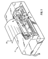
- Fig. 1 is an isometric view of a carriage-type thermal ink jet printer;
- Fig. 2 is a schematic view of the printer having an ink supply cartridge identification system according to a first embodiment;
- Fig. 3 is a schematic view of the printer having an ink supply identification system according to a second embodiment;
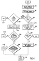
- Fig. 4 is a flowchart depicting the operation of one embodiment of the present invention;
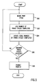
- Fig. 5 is a flowchart depicting the operation of the firing cycle count aspect of the present invention; and
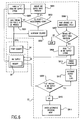
- Fig. 6 is a diagram showing a flowchart of the steps performed by the controller in one embodiment superimposed on a schematic view of the ink supply identification system.
- Referring to Fig. 1, a thermal
ink jet printer 10 is shown. Severalink supply cartridges 2, each having an integrally attachedprint element 54, are mounted on a reciprocating carriage 6. During the printing mode, the carriage 6 translates back and forth on guide rails 7 as depicted by the arrow 4. A recording medium 8, such as paper, is held stationary while the carriage 6 is moving in one direction. Before the carriage 6 moves in the reverse direction, the recording medium 8 is stepped a distance equal to the height of the swath of data being printed by the print elements. Eachprint element 54 has a linear array of nozzles that are aligned in a direction perpendicular to the direction that the carriage is translating. The nozzles face the recording medium and expelink droplets 9 toward the recording medium. - According to a first embodiment as shown in Fig. 2, the
printer 10 is configured to include anonvolatile memory 20. The contents of thememory 20 remain in storage even if the power to theprinter 10 is turned off. Thememory 20 is connected to the printer controller (CPU) 22. When theink supply cartridge 2 is installed, it becomes electrically connected by a series ofconnections 24 to theprinter 10. Theconnections 24 serve to connect theCPU 22 andmemory 20 of theprinter 10 to theprint element 54 of theink supply cartridge 2. Theconnections 24 include a fusible link or other similar programmable device that can be subjected to a current or voltage to permanently alter a signal that can be read through theconnection 24. The fusible link can be, e.g., a narrow aluminum strip disposed over a polysilicon heater (not shown) or, alternatively, an EPROM memory location that can be written in only one direction such as from 1 to 0 or 0 to 1. The heater can be energized to fuse the fusible link and in turn sever theelectrical connection 24. In the following paragraphs, the term fusible link will be used to refer to the class of devices which can permanently record an electrical event and not be subsequently altered. - In a first embodiment, the ink supply identification system includes a fusible link and an ink supply having a serial number. The ink supply identification system according to this embodiment is inexpensive because the serial number can be a bar code, magnetic strip or other economical method of recording a digital code. Although the description below refers to the configuration in which the serial number is on the ink supply, the description also applies to the configuration in which the ink supply and the print element are consolidated to create a replaceable ink jet cartridge.
- Each
ink supply 26 is encoded with a unique serial number or one of a large finite set of serial numbers. In the case where there are a finite set of serial numbers and multiple copies of each serial number exist within the ink supply population, a sufficiently large set of serial numbers must be used so that the probability of obtaining the same number twice in one printer is very small compared to other failure modes in the printer. - As shown in Figure 4, when the printer is turned on or at the start of a job (step S90), the printer detects whether the fusible link of the attached ink supply is blown (step S92) and reads the serial number of the ink supply (step S91). Preferably, the fusible link is integrated with other control circuitry functions so that the electrical connection cannot be tampered with or disabled without also making the printer nonfunctional. If the fusible link is blown, the ink supply has been previously used. If the ink supply has been previously used, the printer compares the ink supply serial number with the serial numbers already stored in memory (step S93). The printer must match the ink supply serial number to an existing serial number within the printer memory in order to enable printing. If no match is found, the printing function is disabled (step S101). If a match is found, the printer checks the remaining ink supply and verifies that ink is left in the supply.
- The printer detects the quantity of ink remaining in the ink supply (step S94). If the quantity remaining is less than a predetermined quantity, the operation of the printer ceases (step S103). If the printer determines that the quantity remaining is greater than or equal to the predetermined quantity (step S96), the printer determines whether the quantity remaining is within a predetermined range of the predetermined quantity (i.e., whether the ink supply, although not fully depleted, is close to being fully depleted) (step S98). If the quantity remaining is within the predetermined range, a warning to that effect is displayed (step 102). In either case, printing of the job then begins (step S100).
- If the fusible link is not blown, the printer records the first usage of the ink supply by blowing the fuse, reads and records the serial number (step S95), and initializes ink usage recording for that supply (step S99). The printer can optionally check for a blown fuse condition to assure that the first usage is recorded (step S97) before initializing ink usage recording. Periodically, as printing is taking place, the nonvolatile memory that stores the amount of ink is read and updated according to the amount of ink used since the last update. These updates should occur frequently to prevent rounding errors from short jobs. The ink supply identification system allows multiple partially used cartridges to be inserted and removed from a printer, but does not allow two printers to share the same cartridge.
- Although the
memory 20 in Fig. 2 is shown as part of the printer, thememory 20 can also be configured as a component of theink supply cartridge 2. Thememory 20 can be included in the control circuitry (not shown) within theprint element 54 by using, e.g., polysilicon/pyrolytic nitride/tantalum as a floating gate erasable transistor device. Alternatively, a second EPROM device can be disposed in the print element to serve as thememory 20. - An embodiment of the present invention in which the
memory 20 is configured as a component of theink supply 26 is shown in Fig. 6. Theprint element 54 and theink supply 26 are shown schematically in relation to theCPU 22 of theprinter 10. Although the print element and ink supply are described below as being severable, the dashed line separating theprint element 54 from theink supply 26 indicates that this embodiment applies to applications using an ink jet cartridge as well. During normal printing, data representing the image to be output is transmitted from theCPU 22 to the ink supply cartridge (S901). These data are a series of "1s" and "0s" that indicate whether or not, respectively, an ink jet of the print element is to be fired to produce a printed pixel at a particular location. At an appropriate interval, a counter is incremented (step S902). In step S903, the count registered in the counter is compared to a predetermined count. The predetermined count is set to a high number of printed pixels according to the particular application, such that the steps described below are executed one or more times during the printing of each page. If the count is less than the predetermined count, theCPU 22 continues to transmit data to theprint element 54 and printing continues. - If the count is greater than the predetermined count, the
CPU 22 initiates an ink supply write protocol (step S904). In step S904, theCPU 22 sends a code to theink supply 26 requesting an identification code. On receipt of the code sequence, the CPU evaluates whether the ink supply is authorized. TheCPU 22 then communicates that it is writing to thememory 20 in theink supply 26. In step S905, the controller erases a "1" from thememory 20 to represent that a specified quantity of ink has been depleted from theink supply 26. The specified quantity of ink is equal to the total capacity of theink supply 26 divided by the number of "1s" stored in thememory 20. According to this routine, the current volume of ink in the ink supply is decreased according to the number of pixels printed (each pixel being equivalent to one drop of ink) based upon the number of "1s" in the memory. - Fig. 6 also shows the steps performed by the
CPU 22 in executing a page advance and/or maintenance routine (step S906). The page advance and/or maintenance routine is performed each time the printer is turned on and at the beginning of each job, as well as at other appropriate intervals. In contrast to the steps described directly above, the page advance and/or maintenance routine is preferably executed when the printer is not printing data so as to take advantage of the full computing power of theCPU 22. In step S907, the CPU determines if an ink supply read protocol should be performed by detecting whether the ink supply is authorized. If the ink supply is not authorized, the printer ceases operation. The validation of the ink supply preferably occurs during start up of the printing operation, while validation during the write cycle as outlined above is optional. Similar to the ink supply write protocol described above in connection with step S904, if theCPU 22 recognizes theink supply 26 as being authorized, theCPU 22 then reads the contents of thememory 20 that represent the quantity of the remaining ink (step S908). Based on the data read from thememory 20, theCPU 22 determines whether thememory 20 contains any "1s" (i.e., whether any ink remains within the ink supply 26) (step S905). If at least a single "1" is present (S909), theCPU 22 determines the exact quantity of ink (step S912), stores this value and enables printing to occur (step 913). - If, on the other hand, at least a single "1" is not present in the memory 20 (step S910), the printer enters an alternative operating mode (step S911) because the
CPU 22 determines that the ink supply is depleted. In the alternative operating mode, theCPU 22 preferably issues a warning to the effect that printing is halted until the current depleted or unauthorized ink supply is replaced. - In addition to detecting whether a fresh ink supply cartridge can be used with the particular printer, the
CPU 22 also determines the number of firing cycles that the currently installed ink supply cartridge has completed. In a preferred embodiment, the number of drops or other appropriate measure of consumed ink is rounded off to suit the particular operating requirements. As shown in Fig. 5, after the printing cycle begins (step S80), theCPU 22 periodically updates the firing cycle count (step S82), stores it in the memory 20 (step S84), and compares it to a predetermined maximum firing cycle count (step S86). As the firing cycle count approaches the maximum firing cycle count, theCPU 22 optionally transmits a signal to a display (not shown) or other similar device to signal the user that a fresh ink supply will soon be required. Once the firing cycle count reaches the maximum firing cycle count, theCPU 22 disables the printer (step S88). - According to a second embodiment as shown in Fig. 3, the
ink supply 26 is separately detachable from either theprint element 54 or theprint element 54 andprinter 10 combination. In Fig. 3, theprint element 54 is included as a removable component of the printer. In this embodiment, theink supply 26 is encoded with a serial number. The serial number of theink supply 26 can be encoded, e.g., by (i) affixing a magnetic strip to the ink supply container, (ii) affixing a bar code or other optically recognizable symbol to the ink supply container, or (iii) providing a circuit or chip within the ink supply that establishes an electrical connection with theprint element 54 andprinter 10 circuity, etc. In the first and second cases of an ink supply having a magnetic strip or a bar code, theCPU 22 receives a detection signal from a magnetic strip reader or a bar code reader (not shown), respectively, when the ink supply is installed. This embodiment permits the manufacturer to account for the distinct usable lives of the ink supply and the print element. In other words, the CPU can signal the user that the currently installed ink supply has been used up, e.g., used six times, while the currently installed print element has not yet reached the maximum firing cycle count, e.g., the equivalent of firing the ink contained in ten ink supplies. - The ink supply of this embodiment could also be configured to provide the user with an indication of the ink supply fill level. In this case, the
CPU 22 compares the current ink supply fill level to a known level stored in thememory 20 to determine whether the ink supply is depleted. The user receives a signal from theCPU 22 that the ink supply is nearly depleted so that a fresh ink supply can be substituted before a new print job is initiated. When a fresh ink supply is installed, theCPU 22 resets the current ink supply level. Additionally, theCPU 22 prevents the user from operating the printer when a spent ink supply has been installed. - In a third embodiment, the additional circuitry required to implement either the first or the second embodiment is included in the
print element 54, either as an integral part of its circuitry or as separate components. In other words, print elements containing a memory could be retrofitted for conventional print elements in conventional printers that use either an ink supply cartridge or a separately connectable ink supply. Installing a print element having the additional circuitry establishes the connection between theCPU 22 of the conventional printer and theprint element 54. - With respect to each of the embodiments, the contents of the
memory 20 can be configured in several ways. First, thememory 20 can include a register of the serial numbers for eachprint element 54 that has been used in the printer 10 (i.e., the "used" register). In this case, theCPU 22 compares the detected serial number to the serial numbers in the used register and permits the printer to continue operating only if the detected serial number matches a number within the used register and if the ink supply of the print element is not depleted. In this case, the print elements having serial numbers that appear within the used register are considered to be unauthorized when their ink supplies are depleted. - Second, the
memory 20 can include a register of authorized numbers (i.e., the "authorized" register). Several serial numbers or ranges of serial numbers are prerecorded in the authorized register by the manufacturer. These authorized serial numbers can be the appropriate types of print elements and ink supply cartridges for a particular printer model. In other words, the manufacturer can ensure that an ink supply cartridge that has a normal physical appearance, but that is otherwise unsuitable for the particular printer, will cause the printer to become disabled if the ink supply cartridge is installed. In this way, the manufacturer can take steps to avoid damage to the printer and prevent the user from inserting improper ink supply cartridges. - Third, the memory can include a register that contains the serial numbers of print elements that have been used more than a recommended number of times (i.e., the "spent" register). Thus, the printer can accept any one of several recognized cartridges that were previously used but not depleted. The spent register contains a counter value for each of the serial numbers contained within a first register. Each time a serial number is detected, the count associated with that serial number is incremented. When the count for a particular print element reaches the recommended number, the
CPU 22 transfers the serial number for that print element from the first register to the spent register. A subsequent attempt to use the print element disables the printer. - The various ways of configuring the memory can be combined. For instance, the memory may include both an authorized register and a used register. Furthermore, although the preceding discussion refers to serial numbers, it is understood that this term encompasses whatever unique indicia is used to designate each independent ink supply cartridge or ink supply.
Claims (13)
- A printer (10) having an ink supply identification system, said ink supply system comprising:an ink supply (26);an ink supply identification corresponding to said ink supply;a print element (54) connected to said ink supply and said printer; andcontrol means (22) for controlling an operation of said printer in response to said ink supply identification, characterised by:said control means including recognition means for recognizing said ink supply identification of said ink supply and for transmitting a signal corresponding to said ink supply identification.
- The printer of claim 1, wherein said recognition means recognizes one of a plurality of signals from said ink supply;wherein one of said plurality of signals indicates that said ink supply is authorized or unauthorised; andwherein one of said plurality of signals indicates that said ink supply is depleted.
- The printer of claims 1 or 2, wherein said control means permits the operation of said printer to continue only if said control means receives a signal indicating that said ink supply is authorized.
- The printer of any of the preceding claims, wherein said recognition means includes ink quantity detection means for detecting a quantity of ink remaining in said ink supply.
- The printer of claim 4, further comprising a memory (20) connected to said control means, wherein said ink quantity detection means detects said quantity of ink remaining in said ink supply by comparing a number of firing cycles completed by said print element of said printer with a predetermined maximum number of firing cycles.
- The printer of claim 1, wherein said ink supply identification is a magnetically encoded strip and said recognition means is a strip reader for reading said magnetically encoded strip.
- The printer of any of the preceding claims, wherein said ink supply (26) and said print element (54) are disposed within a print cartridge (2) and said print cartridge is removably insertible into said printer (10).
- The printer of claim 7, wherein said ink supply is permanently attached to said print cartridge (2) such that a user cannot remove said ink supply from said print cartridge.
- The printer of claim 1, further comprising a memory connected to said control means, said memory containing said ink supply identification; and wherein said memory includes a used ink supply register, said used ink supply register containing at least one used ink supply identification corresponding to an ink supply that has been at least partially depleted by said printer, a spent ink supply register, said spent ink supply register containing at least one spent ink supply identification corresponding to an ink supply that has been depleted by said printer, or an authorized ink supply register, said authorized ink supply register containing at least one authorized ink supply identification corresponding to an authorized ink supply, wherein said authorized ink supply is suited for use in said printer.
- A method of maintaining the reliability of a printer (10) having an ink supply identification system that includes an ink supply (26), a print element (54), and control means (22), the method comprising the steps of:connecting said print element to said printer; andconnecting said ink supply to said print element; characterised by:detecting an ink supply identification of said ink supply; andcontrolling an operation of said printer in accordance with said ink supply identification.
- The method of claim 10, wherein said printer further comprises providing a memory (20), and wherein said step of controlling includes comparing a detected ink supply identification with at least one said ink supply identification stored in said memory.
- The method of claims 10 or 11, further characterised by continuing an operation of said printer if said detected ink supply identification matches said ink supply identification, or discontinuing an operation of said printer if said detected ink supply identification does not match said ink supply identification.
- The method of any one of claims 10 to 12, wherein said step of controlling includes logging a number of completed firing cycles corresponding to a number of drops expelled by said print element; updating said number of completed firing cycles; comparing said number of completed firing cycles to a predetermined maximum number of firing cycles; and disabling said printer when said number of completed firing cycles reaches said maximum number of maximum firing cycles.
Applications Claiming Priority (2)
| Application Number | Priority Date | Filing Date | Title |
|---|---|---|---|
| US36761195A | 1995-01-03 | 1995-01-03 | |
| US367611 | 2003-02-14 |
Publications (2)
| Publication Number | Publication Date |
|---|---|
| EP0720916A2 true EP0720916A2 (en) | 1996-07-10 |
| EP0720916A3 EP0720916A3 (en) | 1997-11-05 |
Family
ID=23447890
Family Applications (1)
| Application Number | Title | Priority Date | Filing Date |
|---|---|---|---|
| EP96300043A Withdrawn EP0720916A3 (en) | 1995-01-03 | 1996-01-03 | Ink supply identification system for a printer |
Country Status (5)
| Country | Link |
|---|---|
| EP (1) | EP0720916A3 (en) |
| JP (1) | JPH08230213A (en) |
| BR (1) | BR9600008A (en) |
| CA (1) | CA2164536A1 (en) |
| MX (1) | MX9505305A (en) |
Cited By (62)
| Publication number | Priority date | Publication date | Assignee | Title |
|---|---|---|---|---|
| EP0804018A2 (en) * | 1996-04-23 | 1997-10-29 | Canon Kabushiki Kaisha | User interface, printing system using user interface and print control method |
| US5699091A (en) * | 1994-12-22 | 1997-12-16 | Hewlett-Packard Company | Replaceable part with integral memory for usage, calibration and other data |
| EP0830947A2 (en) * | 1996-09-19 | 1998-03-25 | Samsung Electronics Co., Ltd. | Ink-jet printer having multiple printer heads |
| GB2321220A (en) * | 1997-01-21 | 1998-07-22 | Hewlett Packard Co | Replaceable ink-jet cartridge with internal ink level detection |
| EP0854043A2 (en) * | 1997-01-21 | 1998-07-22 | Hewlett-Packard Company | Apparatus controlled by data from consumable parts with incorporated memory devices |
| EP0854045A2 (en) * | 1997-01-21 | 1998-07-22 | Hewlett-Packard Company | Ink jet cartridge with separately replaceable ink reservoir |
| EP0878308A2 (en) * | 1997-05-15 | 1998-11-18 | Hewlett-Packard Company | Method and apparatus for prediction of inkjet printhead lifetime |
| EP0882595A2 (en) * | 1997-06-04 | 1998-12-09 | Hewlett-Packard Company | Ink level estimation using drop count and ink level sense |
| EP0925936A2 (en) * | 1997-12-15 | 1999-06-30 | Lexmark International, Inc. | Printer cartridge identification |
| US5956057A (en) * | 1996-08-30 | 1999-09-21 | Hewlett-Packard Company | Ink container having electronic and mechanical features enabling plug compatibility between multiple supply sizes |
| WO1999048694A1 (en) * | 1998-03-21 | 1999-09-30 | E B S Gmbh | Inkjet printer for printing on goods |
| US6019449A (en) * | 1998-06-05 | 2000-02-01 | Hewlett-Packard Company | Apparatus controlled by data from consumable parts with incorporated memory devices |
| EP1000752A2 (en) * | 1998-11-11 | 2000-05-17 | Seiko Epson Corporation | Ink jet type printing apparatus, ink cartridge therefor, and method of controlling the printing apparatus |
| US6065824A (en) * | 1994-12-22 | 2000-05-23 | Hewlett-Packard Company | Method and apparatus for storing information on a replaceable ink container |
| US6089687A (en) * | 1998-03-09 | 2000-07-18 | Hewlett-Packard Company | Method and apparatus for specifying ink volume in an ink container |
| US6113208A (en) * | 1996-05-22 | 2000-09-05 | Hewlett-Packard Company | Replaceable cartridge for a printer including resident memory with stored message triggering data |
| US6120129A (en) * | 1996-04-23 | 2000-09-19 | Canon Kabushiki Kaisha | Ink-jet print method and apparatus |
| US6126265A (en) * | 1997-01-21 | 2000-10-03 | Hewlett-Packard Company | Ink jet printer service station controlled by data from consumable parts with incorporated memory devices |
| US6130695A (en) * | 1995-04-27 | 2000-10-10 | Hewlett-Packard Company | Ink delivery system adapter |
| US6142600A (en) * | 1996-04-23 | 2000-11-07 | Canon Kabushiki Kaisha | Print control method and printer |
| US6154227A (en) * | 1997-12-08 | 2000-11-28 | Hewlett-Packard Company | Apparatus and method for printing compensation |
| US6158836A (en) * | 1996-04-23 | 2000-12-12 | Canon Kabushiki Kaisha | Print method and apparatus |
| US6170937B1 (en) | 1997-01-21 | 2001-01-09 | Hewlett-Packard Company | Ink container refurbishment method |
| WO2001005596A1 (en) * | 1999-07-14 | 2001-01-25 | Seiko Epson Corporation | Ink cartridge, ink jet printer, method of replacing ink cartridge |
| US6227638B1 (en) | 1997-01-21 | 2001-05-08 | Hewlett-Packard Company | Electrical refurbishment for ink delivery system |
| US6260938B1 (en) | 1996-04-23 | 2001-07-17 | Canon Kabushiki Kaisha | Ink-jet printing method and apparatus for printing with inks of different densities |
| EP1066967A3 (en) * | 1999-07-07 | 2001-08-01 | Riso Kagaku Corporation | Image recording apparatus |
| US6271928B1 (en) | 1998-03-04 | 2001-08-07 | Hewlett-Packard Company | Electrical storage device for a replaceable printing component |
| US6312083B1 (en) * | 1999-12-20 | 2001-11-06 | Xerox Corporation | Printhead assembly with ink monitoring system |
| US6318850B1 (en) | 1995-12-04 | 2001-11-20 | Hewlett-Packard Company | Ink container refurbishment system |
| US6322207B1 (en) | 1995-04-27 | 2001-11-27 | Hewlett-Packard Company | Replaceable pump module for receiving replaceable ink supplies to provide ink to an ink jet printing system |
| US6375301B1 (en) | 1997-01-21 | 2002-04-23 | Hewlett-Packard Company | Replaceable cartridge, kit and method for flushing ink from an inkjet printer |
| EP1237725A1 (en) * | 1999-12-08 | 2002-09-11 | Pitney Bowes Inc. | Preventing the unauthorized use of a retaining cartridge |
| US6454381B1 (en) | 2001-04-27 | 2002-09-24 | Hewlett-Packard Company | Method and apparatus for providing ink container extraction characteristics to a printing system |
| EP1310370A3 (en) * | 2001-11-08 | 2004-01-28 | Seiko Epson Corporation | Ink cartridge and recording apparatus |
| US6789883B2 (en) | 2001-05-09 | 2004-09-14 | Hewlett-Packard Development Company, L.P. | Method and apparatus for compensating for ink container extraction characteristics |
| US6969136B1 (en) | 1998-05-25 | 2005-11-29 | Seiko Epson Corporation | Ink cartridge, ink-jet printing apparatus, and refilling device |
| US6978255B1 (en) | 1999-11-26 | 2005-12-20 | Francotyp-Postalia Ag & Co. | Method for protecting a device against operation with unallowed consumables and arrangement for the implementation of the method |
| US7008050B2 (en) | 1995-04-27 | 2006-03-07 | Hewlett-Packard Development Company, L.P. | Ink container refurbishment system |
| US7029082B2 (en) | 2003-07-02 | 2006-04-18 | Hewlett-Packard Development Company, L.P. | Printing device having a printing fluid detector |
| US7249831B2 (en) | 1995-04-27 | 2007-07-31 | Hewlett-Packard Development Company, L.P. | Ink container refurbishment system |
| US7419234B2 (en) | 2006-10-27 | 2008-09-02 | Static Control Components, Inc. | Method and apparatus for spoofing imaging devices |
| EP2022636A1 (en) | 2007-08-10 | 2009-02-11 | Samsung Electronics Co., Ltd. | Image forming apparatus, cartridge and image forming method |
| US7685424B2 (en) * | 2000-02-15 | 2010-03-23 | Silverbrook Research Pty Ltd | Validating untrusted objects and entities |
| US7706019B2 (en) | 2004-06-25 | 2010-04-27 | Hewlett-Packard Development Company, L.P. | Consumable resource option control |
| US7755782B2 (en) | 2004-06-25 | 2010-07-13 | Hewlett-Packard Development Company, L.P. | Consumable resource option control |
| US7904728B2 (en) | 2004-04-22 | 2011-03-08 | Hewlett-Packard Development Company, L.P. | Consumable resource access control |
| WO2013120702A1 (en) | 2012-02-16 | 2013-08-22 | Ebs Ink-Jet Systeme Gmbh | Inkjet printer for labeling goods |
| WO2014070161A1 (en) * | 2012-10-31 | 2014-05-08 | Hewlett-Packard Development Company, L.P. | Method and system to store drop counts |
| WO2017023273A1 (en) * | 2015-07-31 | 2017-02-09 | Hewlett-Packard Development Company, L.P. | Imaging supplies |
| US10875318B1 (en) | 2018-12-03 | 2020-12-29 | Hewlett-Packard Development Company, L.P. | Logic circuitry |
| US10894423B2 (en) | 2018-12-03 | 2021-01-19 | Hewlett-Packard Development Company, L.P. | Logic circuitry |
| US11250146B2 (en) | 2018-12-03 | 2022-02-15 | Hewlett-Packard Development Company, L.P. | Logic circuitry |
| US11292261B2 (en) | 2018-12-03 | 2022-04-05 | Hewlett-Packard Development Company, L.P. | Logic circuitry package |
| US11312146B2 (en) | 2018-12-03 | 2022-04-26 | Hewlett-Packard Development Company, L.P. | Logic circuitry package |
| US11338586B2 (en) | 2018-12-03 | 2022-05-24 | Hewlett-Packard Development Company, L.P. | Logic circuitry |
| US11366913B2 (en) | 2018-12-03 | 2022-06-21 | Hewlett-Packard Development Company, L.P. | Logic circuitry |
| US11364716B2 (en) | 2018-12-03 | 2022-06-21 | Hewlett-Packard Development Company, L.P. | Logic circuitry |
| US11407229B2 (en) | 2019-10-25 | 2022-08-09 | Hewlett-Packard Development Company, L.P. | Logic circuitry package |
| US11429554B2 (en) | 2018-12-03 | 2022-08-30 | Hewlett-Packard Development Company, L.P. | Logic circuitry package accessible for a time period duration while disregarding inter-integrated circuitry traffic |
| US11479047B2 (en) | 2018-12-03 | 2022-10-25 | Hewlett-Packard Development Company, L.P. | Print liquid supply units |
| US11724510B2 (en) | 2018-12-12 | 2023-08-15 | Hewlett-Packard Development Company, L.P. | Interfaces to connect external print fluid supplies with print fluid reservoirs |
Families Citing this family (3)
| Publication number | Priority date | Publication date | Assignee | Title |
|---|---|---|---|---|
| JP3487576B2 (en) | 1997-12-29 | 2004-01-19 | キヤノン株式会社 | Ink jet recording device |
| JP2001260373A (en) * | 2000-03-15 | 2001-09-25 | Mutoh Ind Ltd | Ink jet printer |
| JP2008087425A (en) * | 2006-10-04 | 2008-04-17 | Seiko Epson Corp | Coloring agent management device, its control method, its control program and printer |
Citations (4)
| Publication number | Priority date | Publication date | Assignee | Title |
|---|---|---|---|---|
| US4872027A (en) | 1987-11-03 | 1989-10-03 | Hewlett-Packard Company | Printer having identifiable interchangeable heads |
| US4961088A (en) | 1989-04-20 | 1990-10-02 | Xerox Corporation | Monitor/warranty system for electrostatographic reproducing machines using replaceable cartridges |
| US5283593A (en) | 1988-07-25 | 1994-02-01 | Mannesmann Ag | Ink reservoir for ink printer means having a means to prevent unauthorized refilling |
| US5283594A (en) | 1990-12-18 | 1994-02-01 | Brother Kogyo Kabushiki Kaisha | Color image recording apparatus for recording a color image on a recording medium with color particles with a vibrating print head |
Family Cites Families (8)
| Publication number | Priority date | Publication date | Assignee | Title |
|---|---|---|---|---|
| US5365312A (en) * | 1988-07-25 | 1994-11-15 | Mannesmann Ag | Arrangement for printer equipment for monitoring reservoirs that contain printing medium |
| US5068806A (en) * | 1988-12-02 | 1991-11-26 | Spectra-Physics, Inc. | Method of determining useful life of cartridge for an ink jet printer |
| US5049898A (en) * | 1989-03-20 | 1991-09-17 | Hewlett-Packard Company | Printhead having memory element |
| DE69033377T2 (en) * | 1989-08-05 | 2000-06-29 | Canon Kk | Ink jet recording apparatus and ink cartridge therefor |
| JP3222454B2 (en) * | 1990-02-02 | 2001-10-29 | キヤノン株式会社 | Ink tank cartridge |
| JPH04141442A (en) * | 1990-10-02 | 1992-05-14 | Nec Corp | Ink jet printer |
| IT1256844B (en) * | 1992-06-08 | 1995-12-21 | Olivetti & Co Spa | METHOD AND DEVICE FOR THE RECOGNITION OF THE END-INK IN AN INK-JET PRINT HEAD. |
| JP2839995B2 (en) * | 1992-10-14 | 1998-12-24 | キヤノン株式会社 | Recording device |
-
1995
- 1995-12-06 CA CA 2164536 patent/CA2164536A1/en not_active Abandoned
- 1995-12-14 MX MX9505305A patent/MX9505305A/en unknown
- 1995-12-28 JP JP34361495A patent/JPH08230213A/en not_active Withdrawn
-
1996
- 1996-01-02 BR BR9600008A patent/BR9600008A/en not_active Application Discontinuation
- 1996-01-03 EP EP96300043A patent/EP0720916A3/en not_active Withdrawn
Patent Citations (4)
| Publication number | Priority date | Publication date | Assignee | Title |
|---|---|---|---|---|
| US4872027A (en) | 1987-11-03 | 1989-10-03 | Hewlett-Packard Company | Printer having identifiable interchangeable heads |
| US5283593A (en) | 1988-07-25 | 1994-02-01 | Mannesmann Ag | Ink reservoir for ink printer means having a means to prevent unauthorized refilling |
| US4961088A (en) | 1989-04-20 | 1990-10-02 | Xerox Corporation | Monitor/warranty system for electrostatographic reproducing machines using replaceable cartridges |
| US5283594A (en) | 1990-12-18 | 1994-02-01 | Brother Kogyo Kabushiki Kaisha | Color image recording apparatus for recording a color image on a recording medium with color particles with a vibrating print head |
Cited By (132)
| Publication number | Priority date | Publication date | Assignee | Title |
|---|---|---|---|---|
| US5699091A (en) * | 1994-12-22 | 1997-12-16 | Hewlett-Packard Company | Replaceable part with integral memory for usage, calibration and other data |
| US6065824A (en) * | 1994-12-22 | 2000-05-23 | Hewlett-Packard Company | Method and apparatus for storing information on a replaceable ink container |
| US6305795B2 (en) | 1994-12-22 | 2001-10-23 | Winthrop D. Childers | Ink container having electronic and mechanical features enabling plug compatibility between multiple supply sizes |
| US5835817A (en) * | 1994-12-22 | 1998-11-10 | Hewlett Packard Company | Replaceable part with integral memory for usage, calibration and other data |
| US6764169B2 (en) | 1995-04-27 | 2004-07-20 | Hewlett-Packard Development Company, L.P. | Method and apparatus for providing ink to an ink jet printing system |
| US6322207B1 (en) | 1995-04-27 | 2001-11-27 | Hewlett-Packard Company | Replaceable pump module for receiving replaceable ink supplies to provide ink to an ink jet printing system |
| US7008050B2 (en) | 1995-04-27 | 2006-03-07 | Hewlett-Packard Development Company, L.P. | Ink container refurbishment system |
| US6130695A (en) * | 1995-04-27 | 2000-10-10 | Hewlett-Packard Company | Ink delivery system adapter |
| US7249831B2 (en) | 1995-04-27 | 2007-07-31 | Hewlett-Packard Development Company, L.P. | Ink container refurbishment system |
| US6318850B1 (en) | 1995-12-04 | 2001-11-20 | Hewlett-Packard Company | Ink container refurbishment system |
| US6543872B2 (en) | 1996-04-23 | 2003-04-08 | Canon Kabushiki Kaisha | Ink-jet printing method and apparatus for printing with inks of different densities |
| EP0804018A3 (en) * | 1996-04-23 | 1998-08-19 | Canon Kabushiki Kaisha | User interface, printing system using user interface and print control method |
| US6328403B1 (en) | 1996-04-23 | 2001-12-11 | Canon Kabushiki Kaisha | Print method and apparatus |
| EP1482723A3 (en) * | 1996-04-23 | 2005-04-13 | Canon Kabushiki Kaisha | User interface, printing system using user interface and print control method |
| US6158836A (en) * | 1996-04-23 | 2000-12-12 | Canon Kabushiki Kaisha | Print method and apparatus |
| EP0804018A2 (en) * | 1996-04-23 | 1997-10-29 | Canon Kabushiki Kaisha | User interface, printing system using user interface and print control method |
| US6145950A (en) * | 1996-04-23 | 2000-11-14 | Canon Kabushiki Kaisha | User interface, printing system using user interface and print control method |
| US6120129A (en) * | 1996-04-23 | 2000-09-19 | Canon Kabushiki Kaisha | Ink-jet print method and apparatus |
| US6601938B1 (en) | 1996-04-23 | 2003-08-05 | Canon Kabushiki Kaisha | Ink-jet print method and apparatus |
| US6142600A (en) * | 1996-04-23 | 2000-11-07 | Canon Kabushiki Kaisha | Print control method and printer |
| US6260938B1 (en) | 1996-04-23 | 2001-07-17 | Canon Kabushiki Kaisha | Ink-jet printing method and apparatus for printing with inks of different densities |
| US6113208A (en) * | 1996-05-22 | 2000-09-05 | Hewlett-Packard Company | Replaceable cartridge for a printer including resident memory with stored message triggering data |
| US5956057A (en) * | 1996-08-30 | 1999-09-21 | Hewlett-Packard Company | Ink container having electronic and mechanical features enabling plug compatibility between multiple supply sizes |
| EP0830947A3 (en) * | 1996-09-19 | 1999-03-03 | Samsung Electronics Co., Ltd. | Ink-jet printer having multiple printer heads |
| EP0830947A2 (en) * | 1996-09-19 | 1998-03-25 | Samsung Electronics Co., Ltd. | Ink-jet printer having multiple printer heads |
| EP0854043A3 (en) * | 1997-01-21 | 1998-12-02 | Hewlett-Packard Company | Apparatus controlled by data from consumable parts with incorporated memory devices |
| US5788388A (en) * | 1997-01-21 | 1998-08-04 | Hewlett-Packard Company | Ink jet cartridge with ink level detection |
| GB2321220A (en) * | 1997-01-21 | 1998-07-22 | Hewlett Packard Co | Replaceable ink-jet cartridge with internal ink level detection |
| KR100556000B1 (en) * | 1997-01-21 | 2006-04-21 | 휴렛-팩커드 컴퍼니(델라웨어주법인) | Ink jet cartridge with ink level detection |
| US6126265A (en) * | 1997-01-21 | 2000-10-03 | Hewlett-Packard Company | Ink jet printer service station controlled by data from consumable parts with incorporated memory devices |
| EP0854043A2 (en) * | 1997-01-21 | 1998-07-22 | Hewlett-Packard Company | Apparatus controlled by data from consumable parts with incorporated memory devices |
| EP0854045A3 (en) * | 1997-01-21 | 1998-12-02 | Hewlett-Packard Company | Ink jet cartridge with separately replaceable ink reservoir |
| US6375301B1 (en) | 1997-01-21 | 2002-04-23 | Hewlett-Packard Company | Replaceable cartridge, kit and method for flushing ink from an inkjet printer |
| EP0854045A2 (en) * | 1997-01-21 | 1998-07-22 | Hewlett-Packard Company | Ink jet cartridge with separately replaceable ink reservoir |
| US5812156A (en) * | 1997-01-21 | 1998-09-22 | Hewlett-Packard Company | Apparatus controlled by data from consumable parts with incorporated memory devices |
| US5860363A (en) * | 1997-01-21 | 1999-01-19 | Hewlett-Packard Company | Ink jet cartridge with separately replaceable ink reservoir |
| GB2321220B (en) * | 1997-01-21 | 2001-06-27 | Hewlett Packard Co | Ink-jet cartridge with ink level detection |
| US6170937B1 (en) | 1997-01-21 | 2001-01-09 | Hewlett-Packard Company | Ink container refurbishment method |
| KR100556001B1 (en) * | 1997-01-21 | 2006-04-21 | 휴렛-팩커드 컴퍼니(델라웨어주법인) | Ink jet cartridge with separately replaceable ink reservoir |
| US6227638B1 (en) | 1997-01-21 | 2001-05-08 | Hewlett-Packard Company | Electrical refurbishment for ink delivery system |
| US6161913A (en) * | 1997-05-15 | 2000-12-19 | Hewlett-Packard Company | Method and apparatus for prediction of inkjet printhead lifetime |
| EP0878308A3 (en) * | 1997-05-15 | 2000-01-05 | Hewlett-Packard Company | Method and apparatus for prediction of inkjet printhead lifetime |
| EP0878308A2 (en) * | 1997-05-15 | 1998-11-18 | Hewlett-Packard Company | Method and apparatus for prediction of inkjet printhead lifetime |
| EP0882595A2 (en) * | 1997-06-04 | 1998-12-09 | Hewlett-Packard Company | Ink level estimation using drop count and ink level sense |
| US6151039A (en) * | 1997-06-04 | 2000-11-21 | Hewlett-Packard Company | Ink level estimation using drop count and ink level sense |
| EP0882595A3 (en) * | 1997-06-04 | 2000-03-29 | Hewlett-Packard Company | Ink level estimation using drop count and ink level sense |
| US6154227A (en) * | 1997-12-08 | 2000-11-28 | Hewlett-Packard Company | Apparatus and method for printing compensation |
| US6299274B1 (en) | 1997-12-15 | 2001-10-09 | Lexmark International, Inc. | Thermal ink jet printer cartridge identification |
| EP0925936A2 (en) * | 1997-12-15 | 1999-06-30 | Lexmark International, Inc. | Printer cartridge identification |
| EP0925936A3 (en) * | 1997-12-15 | 2000-01-12 | Lexmark International, Inc. | Printer cartridge identification |
| US6922259B2 (en) | 1998-03-04 | 2005-07-26 | Hewlett-Packard Development Company, L.P. | Electrical storage device for a replaceable printing component |
| US6283586B1 (en) | 1998-03-04 | 2001-09-04 | Hewlett-Packard Company | Method and apparatus for refilling ink containers in a manner that preserves printhead life |
| US6271928B1 (en) | 1998-03-04 | 2001-08-07 | Hewlett-Packard Company | Electrical storage device for a replaceable printing component |
| US6450629B2 (en) | 1998-03-04 | 2002-09-17 | Hewlett-Packard Company | Method and apparatus for refilling ink containers in a manner that preserves printhead life |
| US6559973B2 (en) | 1998-03-04 | 2003-05-06 | Hewlett-Packard Company | Electrical storage device for a replaceable printing component |
| US6089687A (en) * | 1998-03-09 | 2000-07-18 | Hewlett-Packard Company | Method and apparatus for specifying ink volume in an ink container |
| WO1999048694A1 (en) * | 1998-03-21 | 1999-09-30 | E B S Gmbh | Inkjet printer for printing on goods |
| AU747217B2 (en) * | 1998-03-21 | 2002-05-09 | E B S Gmbh | Inkjet printer for printing on goods |
| US7434900B2 (en) | 1998-03-21 | 2008-10-14 | Jan Slomianny | Inkjet printer for printing on goods |
| US7014305B2 (en) | 1998-05-25 | 2006-03-21 | Seiko Epson Corporation | Ink cartridge |
| US6969136B1 (en) | 1998-05-25 | 2005-11-29 | Seiko Epson Corporation | Ink cartridge, ink-jet printing apparatus, and refilling device |
| US6019449A (en) * | 1998-06-05 | 2000-02-01 | Hewlett-Packard Company | Apparatus controlled by data from consumable parts with incorporated memory devices |
| US6533383B1 (en) | 1998-11-11 | 2003-03-18 | Seiko Epson Corporation | Ink jet type printing apparatus ink cartridge therefor and method of controlling the printing apparatus |
| EP1000752A3 (en) * | 1998-11-11 | 2000-06-07 | Seiko Epson Corporation | Ink jet type printing apparatus, ink cartridge therefor, and method of controlling the printing apparatus |
| EP1000752A2 (en) * | 1998-11-11 | 2000-05-17 | Seiko Epson Corporation | Ink jet type printing apparatus, ink cartridge therefor, and method of controlling the printing apparatus |
| US6530519B1 (en) | 1999-07-07 | 2003-03-11 | Riso Kagaku Corporation | Image recording apparatus |
| EP1066967A3 (en) * | 1999-07-07 | 2001-08-01 | Riso Kagaku Corporation | Image recording apparatus |
| US6547363B1 (en) | 1999-07-14 | 2003-04-15 | Seiko Epson Corporation | Ink cartridge, ink jet type printing apparatus using the same, and ink cartridge change control method in the apparatus |
| WO2001005596A1 (en) * | 1999-07-14 | 2001-01-25 | Seiko Epson Corporation | Ink cartridge, ink jet printer, method of replacing ink cartridge |
| US7033009B2 (en) | 1999-07-14 | 2006-04-25 | Seiko Epson Corporation | Ink cartridge, ink-jet type printing apparatus using the same, and ink cartridge change control method in the apparatus |
| US6978255B1 (en) | 1999-11-26 | 2005-12-20 | Francotyp-Postalia Ag & Co. | Method for protecting a device against operation with unallowed consumables and arrangement for the implementation of the method |
| DE19958941B4 (en) * | 1999-11-26 | 2006-11-09 | Francotyp-Postalia Gmbh | Method for protecting a device from being operated with improper consumables |
| EP1237725A1 (en) * | 1999-12-08 | 2002-09-11 | Pitney Bowes Inc. | Preventing the unauthorized use of a retaining cartridge |
| EP1237725A4 (en) * | 1999-12-08 | 2003-03-12 | Pitney Bowes Inc | Preventing the unauthorized use of a retaining cartridge |
| US6312083B1 (en) * | 1999-12-20 | 2001-11-06 | Xerox Corporation | Printhead assembly with ink monitoring system |
| US7685423B1 (en) * | 2000-02-15 | 2010-03-23 | Silverbrook Research Pty Ltd | Validation protocol and system |
| US7685424B2 (en) * | 2000-02-15 | 2010-03-23 | Silverbrook Research Pty Ltd | Validating untrusted objects and entities |
| US6454381B1 (en) | 2001-04-27 | 2002-09-24 | Hewlett-Packard Company | Method and apparatus for providing ink container extraction characteristics to a printing system |
| US6789883B2 (en) | 2001-05-09 | 2004-09-14 | Hewlett-Packard Development Company, L.P. | Method and apparatus for compensating for ink container extraction characteristics |
| US7249821B2 (en) | 2001-11-08 | 2007-07-31 | Seiko Epson Corporation | Ink cartridge and recording apparatus |
| CN100374303C (en) * | 2001-11-08 | 2008-03-12 | 精工爱普生株式会社 | Ink cartridge and recorder |
| EP1310370A3 (en) * | 2001-11-08 | 2004-01-28 | Seiko Epson Corporation | Ink cartridge and recording apparatus |
| US7029104B2 (en) | 2001-11-08 | 2006-04-18 | Seiko Epson Corporation | Ink cartridge and recording apparatus |
| US7029082B2 (en) | 2003-07-02 | 2006-04-18 | Hewlett-Packard Development Company, L.P. | Printing device having a printing fluid detector |
| US7979715B2 (en) | 2004-04-22 | 2011-07-12 | Hewlett-Packard Development Company, L.P. | Replaceable print cartridge |
| US7904728B2 (en) | 2004-04-22 | 2011-03-08 | Hewlett-Packard Development Company, L.P. | Consumable resource access control |
| US7706019B2 (en) | 2004-06-25 | 2010-04-27 | Hewlett-Packard Development Company, L.P. | Consumable resource option control |
| US7755782B2 (en) | 2004-06-25 | 2010-07-13 | Hewlett-Packard Development Company, L.P. | Consumable resource option control |
| US7419234B2 (en) | 2006-10-27 | 2008-09-02 | Static Control Components, Inc. | Method and apparatus for spoofing imaging devices |
| US8301042B2 (en) | 2007-08-10 | 2012-10-30 | Samsung Electronics Co., Ltd. | Image forming apparatus, cartridge and image forming method |
| US8005376B2 (en) | 2007-08-10 | 2011-08-23 | Samsung Electronics Co., Ltd. | Image forming apparatus, cartridge and image forming method |
| EP2022636A1 (en) | 2007-08-10 | 2009-02-11 | Samsung Electronics Co., Ltd. | Image forming apparatus, cartridge and image forming method |
| WO2013120702A1 (en) | 2012-02-16 | 2013-08-22 | Ebs Ink-Jet Systeme Gmbh | Inkjet printer for labeling goods |
| US9061507B2 (en) | 2012-02-16 | 2015-06-23 | Ebs Ink-Jet Systeme Gmbh | Inkjet printer for labeling goods |
| WO2014070161A1 (en) * | 2012-10-31 | 2014-05-08 | Hewlett-Packard Development Company, L.P. | Method and system to store drop counts |
| US9579885B2 (en) | 2012-10-31 | 2017-02-28 | Hewlett-Packard Development Company, L.P. | Method and system to store drop counts |
| WO2017023273A1 (en) * | 2015-07-31 | 2017-02-09 | Hewlett-Packard Development Company, L.P. | Imaging supplies |
| US9740152B2 (en) | 2015-07-31 | 2017-08-22 | Hewlett-Packard Development Company, L.P. | Imaging supply for a printer |
| US9746799B2 (en) | 2015-07-31 | 2017-08-29 | Hewlett-Packard Development Company, L.P. | Imaging supply memory |
| US9857727B2 (en) | 2015-07-31 | 2018-01-02 | Hewlett-Packard Development Company, L.P. | Imaging supply memory |
| US11331924B2 (en) | 2018-12-03 | 2022-05-17 | Hewlett-Packard Development Company, L.P. | Logic circuitry package |
| US11345159B2 (en) | 2018-12-03 | 2022-05-31 | Hewlett-Packard Development Company, L.P. | Replaceable print apparatus component |
| US10940693B1 (en) | 2018-12-03 | 2021-03-09 | Hewlett-Packard Development Company, L.P. | Logic circuitry |
| US11034157B2 (en) | 2018-12-03 | 2021-06-15 | Hewlett-Packard Development Company, L.P. | Logic circuitry |
| US11250146B2 (en) | 2018-12-03 | 2022-02-15 | Hewlett-Packard Development Company, L.P. | Logic circuitry |
| US11292261B2 (en) | 2018-12-03 | 2022-04-05 | Hewlett-Packard Development Company, L.P. | Logic circuitry package |
| US11298950B2 (en) | 2018-12-03 | 2022-04-12 | Hewlett-Packard Development Company, L.P. | Print liquid supply units |
| US11312146B2 (en) | 2018-12-03 | 2022-04-26 | Hewlett-Packard Development Company, L.P. | Logic circuitry package |
| US11312145B2 (en) | 2018-12-03 | 2022-04-26 | Hewlett-Packard Development Company, L.P. | Logic circuitry package |
| US11318751B2 (en) | 2018-12-03 | 2022-05-03 | Hewlett-Packard Development Company, L.P. | Sensor circuitry |
| US10875318B1 (en) | 2018-12-03 | 2020-12-29 | Hewlett-Packard Development Company, L.P. | Logic circuitry |
| US11331925B2 (en) | 2018-12-03 | 2022-05-17 | Hewlett-Packard Development Company, L.P. | Logic circuitry |
| US11338586B2 (en) | 2018-12-03 | 2022-05-24 | Hewlett-Packard Development Company, L.P. | Logic circuitry |
| US11345156B2 (en) | 2018-12-03 | 2022-05-31 | Hewlett-Packard Development Company, L.P. | Logic circuitry package |
| US11345158B2 (en) | 2018-12-03 | 2022-05-31 | Hewlett-Packard Development Company, L.P. | Logic circuitry package |
| US10894423B2 (en) | 2018-12-03 | 2021-01-19 | Hewlett-Packard Development Company, L.P. | Logic circuitry |
| US11345157B2 (en) | 2018-12-03 | 2022-05-31 | Hewlett-Packard Development Company, L.P. | Logic circuitry package |
| US11351791B2 (en) | 2018-12-03 | 2022-06-07 | Hewlett-Packard Development Company, L.P. | Logic circuitry package |
| US11366913B2 (en) | 2018-12-03 | 2022-06-21 | Hewlett-Packard Development Company, L.P. | Logic circuitry |
| US11364724B2 (en) | 2018-12-03 | 2022-06-21 | Hewlett-Packard Development Company, L.P. | Logic circuitry package |
| US11364716B2 (en) | 2018-12-03 | 2022-06-21 | Hewlett-Packard Development Company, L.P. | Logic circuitry |
| US11787194B2 (en) | 2018-12-03 | 2023-10-17 | Hewlett-Packard Development Company, L.P. | Sealed interconnects |
| US11407228B2 (en) | 2018-12-03 | 2022-08-09 | Hewlett-Packard Development Company, L.P. | Logic circuitry package |
| US11427010B2 (en) | 2018-12-03 | 2022-08-30 | Hewlett-Packard Development Company, L.P. | Logic circuitry |
| US11429554B2 (en) | 2018-12-03 | 2022-08-30 | Hewlett-Packard Development Company, L.P. | Logic circuitry package accessible for a time period duration while disregarding inter-integrated circuitry traffic |
| US11479046B2 (en) | 2018-12-03 | 2022-10-25 | Hewlett-Packard Development Company, L.P. | Logic circuitry for sensor data communications |
| US11479047B2 (en) | 2018-12-03 | 2022-10-25 | Hewlett-Packard Development Company, L.P. | Print liquid supply units |
| US11511546B2 (en) | 2018-12-03 | 2022-11-29 | Hewlett-Packard Development Company, L.P. | Logic circuitry package |
| US11625493B2 (en) | 2018-12-03 | 2023-04-11 | Hewlett-Packard Development Company, L.P. | Logic circuitry |
| US11738562B2 (en) | 2018-12-03 | 2023-08-29 | Hewlett-Packard Development Company, L.P. | Logic circuitry |
| US11724510B2 (en) | 2018-12-12 | 2023-08-15 | Hewlett-Packard Development Company, L.P. | Interfaces to connect external print fluid supplies with print fluid reservoirs |
| US11407229B2 (en) | 2019-10-25 | 2022-08-09 | Hewlett-Packard Development Company, L.P. | Logic circuitry package |
Also Published As
| Publication number | Publication date |
|---|---|
| BR9600008A (en) | 1998-01-21 |
| MX9505305A (en) | 1997-01-31 |
| JPH08230213A (en) | 1996-09-10 |
| CA2164536A1 (en) | 1996-07-04 |
| EP0720916A3 (en) | 1997-11-05 |
Similar Documents
| Publication | Publication Date | Title |
|---|---|---|
| EP0720916A2 (en) | Ink supply identification system for a printer | |
| EP0956962B1 (en) | Method and apparatus for identifying parameters in a replaceable printing component | |
| EP1237725B1 (en) | Preventing the unauthorized use of a retaining cartridge | |
| JP3827879B2 (en) | Electrical regeneration method for ink distributor | |
| US5835817A (en) | Replaceable part with integral memory for usage, calibration and other data | |
| KR100485565B1 (en) | Inkjet printer service station controlled by data from consumable parts with incorporated memory devices | |
| US6039430A (en) | Method and apparatus for storing and retrieving information on a replaceable printing component | |
| EP0854043B1 (en) | Apparatus controlled by data from consumable parts with incorporated memory devices | |
| EP0956963B1 (en) | Method and apparatus for transferring data between a printer and a replaceable printing component | |
| US7618138B2 (en) | Ink stick with electronically-readable memory device | |
| US6533383B1 (en) | Ink jet type printing apparatus ink cartridge therefor and method of controlling the printing apparatus | |
| US8128186B2 (en) | Non-volatile memory data integrity validation | |
| US20020171703A1 (en) | Printer cartridge with memory for printer control and adjustment of printer settings | |
| KR100516700B1 (en) | Printing apparatus and control methed therefor and its recording medium | |
| JP3902928B2 (en) | Image processing apparatus, information processing apparatus, ordering method, ordering processing method, storage medium, and program | |
| JP4259001B2 (en) | Image forming apparatus | |
| JP4075943B2 (en) | Printer, printer system, and error detection method in printer | |
| JP4193002B2 (en) | Printer and error check method in printer | |
| KR20060020947A (en) | Image forming apparatus with data processing unit for the consumption goods |
Legal Events
| Date | Code | Title | Description |
|---|---|---|---|
| PUAI | Public reference made under article 153(3) epc to a published international application that has entered the european phase |
Free format text: ORIGINAL CODE: 0009012 |
|
| AK | Designated contracting states |
Kind code of ref document: A2 Designated state(s): DE FR GB |
|
| PUAL | Search report despatched |
Free format text: ORIGINAL CODE: 0009013 |
|
| AK | Designated contracting states |
Kind code of ref document: A3 Designated state(s): DE FR GB |
|
| 17P | Request for examination filed |
Effective date: 19980506 |
|
| STAA | Information on the status of an ep patent application or granted ep patent |
Free format text: STATUS: THE APPLICATION HAS BEEN WITHDRAWN |
|
| 18W | Application withdrawn |
Withdrawal date: 19981222 |