EP0720918A2 - Edge insensitive pixel deletion method for printing high resolution image - Google Patents
Edge insensitive pixel deletion method for printing high resolution image Download PDFInfo
- Publication number
- EP0720918A2 EP0720918A2 EP96300072A EP96300072A EP0720918A2 EP 0720918 A2 EP0720918 A2 EP 0720918A2 EP 96300072 A EP96300072 A EP 96300072A EP 96300072 A EP96300072 A EP 96300072A EP 0720918 A2 EP0720918 A2 EP 0720918A2
- Authority
- EP
- European Patent Office
- Prior art keywords
- pixel
- pixels
- image
- edge
- row
- Prior art date
- Legal status (The legal status is an assumption and is not a legal conclusion. Google has not performed a legal analysis and makes no representation as to the accuracy of the status listed.)
- Granted
Links
Images


Classifications
-
- G—PHYSICS
- G06—COMPUTING; CALCULATING OR COUNTING
- G06K—GRAPHICAL DATA READING; PRESENTATION OF DATA; RECORD CARRIERS; HANDLING RECORD CARRIERS
- G06K15/00—Arrangements for producing a permanent visual presentation of the output data, e.g. computer output printers
- G06K15/02—Arrangements for producing a permanent visual presentation of the output data, e.g. computer output printers using printers
- G06K15/10—Arrangements for producing a permanent visual presentation of the output data, e.g. computer output printers using printers by matrix printers
- G06K15/102—Arrangements for producing a permanent visual presentation of the output data, e.g. computer output printers using printers by matrix printers using ink jet print heads
Definitions
- This invention relates to printing and more particularly, to a method of altering a high resolution pixel image to produce a pixel image that is capable of being visibly reproduced by a printer having a lower resolution.
- An ink jet printhead selectively ejects droplets of ink from a plurality of drop ejectors to create a desired image on an image receiving medium, such as paper.
- the printhead typically comprises an array of drop ejectors that convey ink to the image receiving medium.
- the printhead moves back and forth relative to the image receiving medium to print the images in swaths.
- US-A-4,774,530 shows a general configuration of a typical ink jet printer.
- ink jet printers have a 300 dots per inch (dpi) (12 dots/mm) resolution along the horizontal axis (also called the raster scan axis). Ink jet printers also typically have a 300 dpi vertical resolution so as to form round individual ink droplets that form the pixel images on the paper. These ink jet printers are therefore designed to print 300 dpi by 300 dpi output images. However, increased resolution is desired to print higher resolution images. For example, it may be desirable to print a 300 dpi by 600 dpi (24 dots/mm) pixel image using a 300 dpi ink jet printhead.
- dpi dots per inch
- 600 dpi 24 dots/mm
- the effective resolution of an ink jet printer can be increased along the horizontal axis (or raster scan axis) by energizing or firing the ink jets at a higher rate. This requires redesigning the ink jet firing head and therefore results in a substantially higher cost. It is also possible to increase the effective resolution along the raster scan axis by slowing down the rate at which the printhead moves across the paper. However, this results in excessive ink being deposited on the paper due to excessive ink drop overlap.
- US-A-5,270,728 to Lund et al. discloses a method for multiplying the speed resolution of a raster scanning device such as an ink jet printer.
- a 300 dpi x 600 dpi pixel image is mapped to a corresponding, non-overlapping physical dot image and the ink jets are fired responsive to the dot image to direct ink droplets onto the paper at 600 dpi resolution grid timing to effectively double the horizontal resolution of the pixel image. This is done without increasing the firing rate of the printhead.
- US-A-5,270,728 describes thinning the pixel image before it is printed by selectively turning off pixels within the pixel image by referencing the edges of the pixel image. More specifically, US-A-5,270,728 describes a method of maintaining selected ones of the pixels in an ON state based on ON pixel adjacency and edge proximity criteria.
- FIG. 1 shows a pixel image 200 that is desired to be printed by the ink jet printer.
- each pixel is represented by a corresponding rectangle having a 300 dpi vertical and horizontal resolution.
- each row is consecutively numbered 9, 10, 11, 12, 13, 14, 15 and 16.
- Each of the columns of the pixel image 200 is labelled with a corresponding letter A, B, C, D, E, F, G and H.
- the columns extend in the raster scanning (or horizontal) direction X.
- the rows extend in the slow scan (or vertical) direction Y.
- the pixel in the upper left hand corner of the pixel image 200 is labelled as pixel 9A.
- the pixel in the bottom right hand corner is labelled as pixel 16H.
- Figure 2 shows an altered pixel image 210 according to the method described in US-A-5,270,728.
- selected pixels are turned OFF so that no two adjacent pixels are maintained ON.
- the left hand edge (column A) is always maintained in an ON state.
- the second to last pixel in each of the respective rows is always maintained ON while turning OFF the last pixel in each row.
- pixel 9D is maintained ON while pixel 9E is turned OFF.
- the method described in US-A-5,270,728 is concerned with determining the proximity (or closeness) of a pixel to an edge of a pixel row.
- the method of US-A-5,270,728 results in all the pixels in column B being turned OFF. This is primarily because the left hand edge (i.e., column A) of the pixel image 200 is defined by a straight edge.
- the OFF pixels in column B can lead to visual problems (such as visual texture) when the altered pixel image 210 is mapped and printed according to the method described by US-A-5,270,728.
- Figure 3 shows a mapping process described in US-A-5,270,728 whereby each pixel that was maintained ON during the altering step (i.e., following Figure 2) is subsequently mapped with an OFF pixel to its immediate right.
- dot 60 corresponds to ON pixel 9A and OFF pixel 9B.
- the resulting dot structure represents the 300 dpi resolution of the printhead.
- the altered pixel image 210 described in Figure 2 is mapped so that each ON pixel is mapped to a dot 60 with a corresponding OFF pixel to its immediate right.
- the dot structure of Figure 3 is then raster scanned by the ink jet printer to print the pixel image.
- US-A-5,279,728 suffers from several problems that effect the visual quality of the resulting image on the copy sheet. For example, when all the pixels in a respective column are turned OFF such as in column B of Figure 2, visual texture problems may result on the copy sheet. Rows 9 and 10 also illustrate additional problems caused by rows having five pixels. When two or more pixel rows of a five pixel width are vertically aligned, visible white gaps may occur down the centers of the rows. This is illustrated by pixels 9C and 10C in Figure 3. That is, by using the method of US-A-5,270,728, contiguous regions of two OFF pixels may occur within a row resulting in visual defects of the resulting image on the copy sheet.
- this invention provides a method of increasing the effective resolution of a printhead without the need for edge proximity criteria. This invention therefore provides a much simpler method than that described in US-A-5,270,728 and accordingly results in an easier to implement method.
- This invention also provides a method of printing an image having a defined resolution along a given axis using an ink jet printer that has a predetermined resolution less than the defined resolution of the image.
- the present invention provides a method of printing an image having a defined resolution along a given axis using an ink jet printer having a predetermined resolution along the given axis less than the defined resolution of the image, the image comprising a first pixel row of consecutively numbered ON pixels extending along the given axis from a first left edge pixel to a first right edge pixel and a second pixel row of consecutively numbered ON pixels extending along the given axis from a second right edge pixel to a second left edge pixel, the method comprising the steps of: (a) receiving the image having the defined resolution along the given axis; (b) turning OFF even numbered pixels from the first pixel row; (c) turning OFF even numbered pixels from the second pixel row; and (d) after steps (b) and (c), printing marks at areas corresponding to remaining ON pixels in the first pixel row and remaining ON pixels in the second pixel row, the marks visibly reproducing the image at the defined resolution along the given axis.
- Each row of the image is respectively numbered as odd or even. Pixels within contiguous blocks of black (ON) pixels in each row are then appropriately numbered, beginning at an edge of each contiguous block. Even-numbered pixels are deleted from odd-numbered pixel rows starting with the left-most pixel in each block. In even-numbered rows, the even-numbered pixels are deleted starting from the right-most pixel and proceeding to the left. Subsequently, the ink jet printer fires ink drops at areas corresponding to the remaining ON pixels in the resulting image. This visibly reproduces the pixel image at the defined resolution. The apparent jaggedness, or "zipper-like" appearance of a vertical edge in the bitmap image is smoothed out by interactions between the ink and paper.
- the defined resolution along the given axis is approximately 600 dots per inch and the predetermined resolution along the given axis is approximately 300 dots per inch.
- the receiving step comprises receiving the image in a memory.
- the turning OFF steps are performed in the memory.
- the invention further provides a method for use with a printer, according to claim 6 of the appended claims
- the method preferably further comprises the step of altering subsequently odd-numbered pixel rows by turning OFF selected pixels and by maintaining ON selected pixels, each altered subsequently odd-numbered pixel row having no adjacent ON selected pixels and no adjacent OFF selected pixels.
- the method preferably further comprises the step of altering subsequently even-numbered pixel rows by turning OFF selected pixels and by maintaining ON selected pixels, each altered subsequently even-numbered pixel row having no adjacent ON selected pixels and no adjacent OFF selected pixels.
- the method preferably further comprises the step of raster scanning each altered subsequently odd-numbered pixel row and each altered subsequently even-numbered pixel row with the ink jet printer to visibly reproduce the image at the defined resolution.
- the first pixel row altering step comprises the step of selectively examining each pixel in the first pixel row, starting with the first ON edge pixel, to alternately label each pixel as one of an ON pixel and an OFF pixel, the labelling proceeding in the first direction, the first ON edge pixel being labeled as one of the ON pixels.
- the second pixel row altering step comprises the step of selectively examining each pixel in the second pixel row, starting with the third ON edge pixel to alternately label each pixel as one of an ON pixel and an OFF pixel, the labelling proceeding in the direction opposite to the first direction, the third ON edge pixel being labeled as one of the ON pixels.
- the invention further provides a printing method according to claim 7 of the appended claims.
- the invention further provides a printing method according to claim 8 of the appended claims.
- the invention further provides a method of printing an image with a printer, according to claim 9 of the appended claims.
- the first pixel row altering step comprises alternately maintaining ON selected pixels and turning OFF selected pixels of the first pixel row, in consecutive order, from the first edge to the second edge, the altered pixel image being represented by the maintained ON selected pixels.
- the second pixel row altering step comprises and alternately maintaining ON selected pixels and turning OFF selected pixels of the second pixel row, in consecutive order, from the second edge to the first edge.
- the invention further provides a programmable image processing apparatus when suitably programmed for carrying out the method of any of the appended claims or according to any of the particular embodiments described herein.
- Figure 7 shows a carriage-type ink jet printing device 20.
- a linear array of droplet-producing channels is housed in the printhead 22 of a reciprocal carriage assembly 24.
- Ink droplets 26 are propelled to a receiving medium 28 that is stepped by a motor 30 a preselected distance in the direction of arrow 32 each time the printhead 22 traverses across the receiving medium 28 in the direction indicated by arrow 32.
- the receiving medium 28, such as paper, can be stored on the supply roll 34 and stacked onto a take-up roll 36 by a stepper motor 30 or other means well known in the art.
- the printhead 22 is fixedly mounted on the support base 38, which is adapted for reciprocal movement using any well known means such as the two parallel guide rails 40.
- the reciprocal movement of the printhead 22 may be achieved by a cable 42 and a pair of rotatable pulleys 44, one of which is powered by a reversible motor 46.
- the printhead 22 is generally moved across the receiving medium 28 perpendicularly to the direction the receiving medium 28 is moved by the motor 30.
- other structures for reciprocating the carriage assembly 24 are also known within the art.
- the printhead 22 may also be connected to a controller 50 that will be used with embodiments of the present invention to receive a pixel image at a resolution greater than that of the printhead 22.
- the received pixel image may be a 300x600 dpi image while the printhead has a 300 dpi resolution.
- Other resolutions are also within the scope of this invention.
- the controller 50 may include hardware or software to carry out the present invention as will be described below. Further, it is understood that the above description of the ink jet printing device 20 is merely illustrative and is not limiting. That is, other structures are also within the scope of this invention.
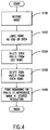
- FIG. 4 shows a flowchart describing an embodiment of the present invention that will be described with respect to Figures 5 and 6.
- a pixel image 200 is received in the controller 50 in step 100.
- the image may be created from a scanning device, a ROS, a computer or other similar devices.
- the image that is received is the pixel image 200 shown in Figure 1.
- each of the pixel rows is appropriately numbered and labeled as either an odd or even row. For example, rows 9, 11, 13 and 15 correspond to odd-numbered rows while rows 10, 12, 14 and 16 correspond to even-numbered rows. While this embodiment will be described with respect to step 102 as labeling each of the rows as either odd or even, it is appreciated that this step may be part of other steps as other embodiments inherently determine which rows are odd and even by examining the rows in succession.
- step 104 the even-numbered pixels in each contiguous block of ON pixels are turned OFF for each of the odd rows 9, 11, 13 and 15. For example, in row 11, the pixels 11B, 11D and 11F are turned OFF. Further, in row 13 the pixels 13B, 13D and 13F are also turned OFF. Therefore, step 104 operates without respect to the right-hand edge unlike the method described in US-A-5,270,728.
- the left-most pixel 9A is first maintained ON. Then, the second pixel 9B is examined. If the pixel to its immediate left (9A) is maintained ON then the current pixel 9B is turned OFF. The third pixel 9C is then examined by looking at the pixel to its immediate left (9B). Because the pixel to the immediate left (9B) is OFF, the current pixel is maintained ON.
- operation proceeds from left to right (i.e., in the raster scan direction) to identify a current pixel as an ON pixel if and only if the pixel to the left of the current pixel is OFF.
- the pixel to the left may be OFF in the original bitmap or it may have been turned OFF during the previous step.
- a pixel from the original bitmap is not identified as an ON pixel unless the pixel to its immediate left is OFF.
- step 106 the even-numbered pixels for each of the even rows 10, 12, 14 and 16 are turned OFF starting from the right-most ON pixel in each contiguous block of ON pixels.
- the pixel 12F is the right-most ON pixel of a block of contiguous ON pixels in pixel row 12. Accordingly, pixel 12E, 12C and 12A are turned OFF for pixel row 12.
- pixel 14G is the right-most pixel and accordingly pixels 14F, 14D and 14B are turned OFF. Therefore, each pixel corresponding to the right edge (in an even-numbered row) is maintained ON without regard to the left-hand edge of the respective pixel row.
- operation proceeds from right to left (opposite to the raster scan direction) to identify a current pixel as an ON pixel if and only if the pixel to the right of the current pixel is OFF.
- the pixel to the right may be OFF from the original bitmap or it may have been turned OFF during the previous step.
- a pixel from the original bitmap is not identified as an ON pixel unless the pixel to its immediate right is OFF.
- the remaining ON pixels within the altered image 220 are appropriately printed using the printhead 22 having a lesser resolution than that of the original pixel image 200.
- the printhead has a 300 dpi (12 dots/mm) resolution while the pixel image 200 is a 300 dpi x 600 dpi (12 x 24 dots/mm) image.
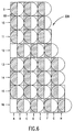
- Figure 6 shows each remaining ON pixel in the altered image 220 being mapped to a dot 60 corresponding to a 300 dpi ink droplet.
- each ON pixel of the altered image 220 is mapped with an OFF pixel to its immediate right.
- the altered image 220 within the controller 50 is raster scanned so as to produce the dots 60 on the receiving medium 28 so as to visibly reproduce the pixel image 200 at the printhead's resolution.
- the mapping can result in "enlarging" the image as the last dots in rows 9, 10, 12-14 and 16 extend beyond the end of the pixel row of the original pixel image 200.
- the above-described method does not require as complicated an algorithm as that described in US-A-5,270,728. Furthermore, the present invention avoids problems of the prior art that require the algorithm to always be sensitive to both the left and right hand edges (i.e., the edge proximity).
- the above-described method is preferably carried out in the controller 50 by use of software on a host computer where the bits of each scan line are considered serially. That is, each of the odd-numbered rows is examined in a left-to-right manner while each of the even-numbered rows are examined in a right-to-left manner. In so doing, a state bit may be retained to record the state of the last pixel. Thus, if a white pixel is encountered, the state bit may be set to white. However, if a black pixel is encountered, the pixel is set to white if and only if the state variable is black. The state variable is then set to whatever the pixel was set to.
- An inkjet printer with a reciprocating printhead 22 normally has some number (typically 48 or more) of jets or channels that are configured in an orientation perpendicular to the direction of travel of the printhead 22. All of these jets or channels can fire essentially simultaneously to produce a vertical column of pixels at each location. In this way, as the printhead 22 traverses the width of the receiving medium 28, an entire swath of pixels is printed. Each swath is a set of pixels the width of the receiving medium 28 and the height of the printhead 22.
- a dedicated memory buffer (also referred to as the swath buffer) is used within the controller 50 to store the image data for an entire swath prior to the traverse of the printhead 22 across the receiving medium 28.
- the invention operates on the data in the swath buffer prior to its transmission to the printhead 22.
- Hardware operation can turn a pixel OFF if the previous pixel is ON. This operation is a logical AND with the complement of the previous pixel.
- two or more passes are preferably made over the swath buffer, with half of the passes being in the left to right direction, and the other half of the passes being in the right to left direction.
- Each pass treats some number (up to half) of the scanlines in the swath buffer in parallel. Preferably only two passes are needed, one in a left to right direction, processing the odd-numbered rows in parallel, and one in a right to left direction, processing the even-numbered rows in parallel.
- Embodiments in which a larger number of passes is used to process sub-sections of a swath are also within the scope of this invention.
- a left to right pass is described with respect to Figure 8.
- a counter N representative of the number of consecutive ON pixels is set to one in step 130.
- the counter N is not set to 1 until the first ON pixel (i.e., the leftmost) is encountered for a respective row.
- each row is individually processed with respect to that respective row even though all of the odd-numbered rows are being processed simultaneously (i.e., in parallel).
- each row will include its own counter N.
- the processing will be described with respect to one counter N.
- a current column is input as the leftmost column in the swath for the odd-numbered rows.
- a decision is made whether the current column is the leftmost in the swath based on the counter N.
- step 135. If so, then the current column is printed by the printhead 22 in step 135.
- the current column is logically inverted in step 136.
- the NEXT column in the swath for the odd-numbered rows is then obtained in step 138 and the counter N is incremented in step 140.
- step 142 a logical AND occurs between the inverted scan column (from step 136) and the next column (from step 138).
- the logical AND result is sent to the printhead 22 in step 144. Operation continues by returning to step 134.
- a right to left pass occurs in a similar manner to that of Figure 8. However, in a right to left pass, the current column that is input in step 132 is the rightmost column in the swath for the even-numbered rows. Step 134 decides whether the current column is the rightmost ON pixel in the swath. Operation continues in a similar manner except the NEXT column in step 133 proceeds in a right to left manner.
Abstract
Description
- This invention relates to printing and more particularly, to a method of altering a high resolution pixel image to produce a pixel image that is capable of being visibly reproduced by a printer having a lower resolution.
- An ink jet printhead selectively ejects droplets of ink from a plurality of drop ejectors to create a desired image on an image receiving medium, such as paper. The printhead typically comprises an array of drop ejectors that convey ink to the image receiving medium. In a carriage-type ink jet printhead, the printhead moves back and forth relative to the image receiving medium to print the images in swaths. US-A-4,774,530 shows a general configuration of a typical ink jet printer.
- Many commercially available ink jet printers have a 300 dots per inch (dpi) (12 dots/mm) resolution along the horizontal axis (also called the raster scan axis). Ink jet printers also typically have a 300 dpi vertical resolution so as to form round individual ink droplets that form the pixel images on the paper. These ink jet printers are therefore designed to print 300 dpi by 300 dpi output images. However, increased resolution is desired to print higher resolution images. For example, it may be desirable to print a 300 dpi by 600 dpi (24 dots/mm) pixel image using a 300 dpi ink jet printhead. The effective resolution of an ink jet printer can be increased along the horizontal axis (or raster scan axis) by energizing or firing the ink jets at a higher rate. This requires redesigning the ink jet firing head and therefore results in a substantially higher cost. It is also possible to increase the effective resolution along the raster scan axis by slowing down the rate at which the printhead moves across the paper. However, this results in excessive ink being deposited on the paper due to excessive ink drop overlap.
- US-A-5,270,728 to Lund et al., the disclosure of which is incorporated herein by reference, discloses a method for multiplying the speed resolution of a raster scanning device such as an ink jet printer. A 300 dpi x 600 dpi pixel image is mapped to a corresponding, non-overlapping physical dot image and the ink jets are fired responsive to the dot image to direct ink droplets onto the paper at 600 dpi resolution grid timing to effectively double the horizontal resolution of the pixel image. This is done without increasing the firing rate of the printhead.
- US-A-5,270,728 describes thinning the pixel image before it is printed by selectively turning off pixels within the pixel image by referencing the edges of the pixel image. More specifically, US-A-5,270,728 describes a method of maintaining selected ones of the pixels in an ON state based on ON pixel adjacency and edge proximity criteria.
- Figure 1 shows a
pixel image 200 that is desired to be printed by the ink jet printer. In Figure 1, each pixel is represented by a corresponding rectangle having a 300 dpi vertical and horizontal resolution. For ease of illustration, each row is consecutively numbered 9, 10, 11, 12, 13, 14, 15 and 16. Each of the columns of thepixel image 200 is labelled with a corresponding letter A, B, C, D, E, F, G and H. The columns extend in the raster scanning (or horizontal) direction X. The rows extend in the slow scan (or vertical) direction Y. As an example, the pixel in the upper left hand corner of thepixel image 200 is labelled as pixel 9A. Similarly, the pixel in the bottom right hand corner is labelled as pixel 16H. - Figure 2 shows an altered
pixel image 210 according to the method described in US-A-5,270,728. As can be seen by Figure 2, selected pixels are turned OFF so that no two adjacent pixels are maintained ON. Furthermore, the left hand edge (column A) is always maintained in an ON state. Furthermore, the second to last pixel in each of the respective rows is always maintained ON while turning OFF the last pixel in each row. For example, pixel 9D is maintained ON while pixel 9E is turned OFF. Thus, the method described in US-A-5,270,728 is concerned with determining the proximity (or closeness) of a pixel to an edge of a pixel row. - As can be seen by Figure 2, the method of US-A-5,270,728 results in all the pixels in column B being turned OFF. This is primarily because the left hand edge (i.e., column A) of the
pixel image 200 is defined by a straight edge. The OFF pixels in column B can lead to visual problems (such as visual texture) when the alteredpixel image 210 is mapped and printed according to the method described by US-A-5,270,728. - Figure 3 shows a mapping process described in US-A-5,270,728 whereby each pixel that was maintained ON during the altering step (i.e., following Figure 2) is subsequently mapped with an OFF pixel to its immediate right. For example,
dot 60 corresponds to ON pixel 9A and OFF pixel 9B. The resulting dot structure represents the 300 dpi resolution of the printhead. Thus, the alteredpixel image 210 described in Figure 2 is mapped so that each ON pixel is mapped to adot 60 with a corresponding OFF pixel to its immediate right. The dot structure of Figure 3 is then raster scanned by the ink jet printer to print the pixel image. - US-A-5,279,728 suffers from several problems that effect the visual quality of the resulting image on the copy sheet. For example, when all the pixels in a respective column are turned OFF such as in column B of Figure 2, visual texture problems may result on the copy sheet.
Rows - To solve these and other problems, this invention provides a method of increasing the effective resolution of a printhead without the need for edge proximity criteria. This invention therefore provides a much simpler method than that described in US-A-5,270,728 and accordingly results in an easier to implement method.
- This invention also provides a method of printing an image having a defined resolution along a given axis using an ink jet printer that has a predetermined resolution less than the defined resolution of the image.
- The present invention provides a method of printing an image having a defined resolution along a given axis using an ink jet printer having a predetermined resolution along the given axis less than the defined resolution of the image, the image comprising a first pixel row of consecutively numbered ON pixels extending along the given axis from a first left edge pixel to a first right edge pixel and a second pixel row of consecutively numbered ON pixels extending along the given axis from a second right edge pixel to a second left edge pixel, the method comprising the steps of: (a) receiving the image having the defined resolution along the given axis; (b) turning OFF even numbered pixels from the first pixel row; (c) turning OFF even numbered pixels from the second pixel row; and (d) after steps (b) and (c), printing marks at areas corresponding to remaining ON pixels in the first pixel row and remaining ON pixels in the second pixel row, the marks visibly reproducing the image at the defined resolution along the given axis.
- Each row of the image is respectively numbered as odd or even. Pixels within contiguous blocks of black (ON) pixels in each row are then appropriately numbered, beginning at an edge of each contiguous block. Even-numbered pixels are deleted from odd-numbered pixel rows starting with the left-most pixel in each block. In even-numbered rows, the even-numbered pixels are deleted starting from the right-most pixel and proceeding to the left. Subsequently, the ink jet printer fires ink drops at areas corresponding to the remaining ON pixels in the resulting image. This visibly reproduces the pixel image at the defined resolution. The apparent jaggedness, or "zipper-like" appearance of a vertical edge in the bitmap image is smoothed out by interactions between the ink and paper.
- Preferably, the defined resolution along the given axis is approximately 600 dots per inch and the predetermined resolution along the given axis is approximately 300 dots per inch.
- Preferably, the receiving step comprises receiving the image in a memory. Preferably, the turning OFF steps are performed in the memory.
- The invention further provides a method for use with a printer, according to claim 6 of the appended claims
- The method preferably further comprises the step of altering subsequently odd-numbered pixel rows by turning OFF selected pixels and by maintaining ON selected pixels, each altered subsequently odd-numbered pixel row having no adjacent ON selected pixels and no adjacent OFF selected pixels.
- The method preferably further comprises the step of altering subsequently even-numbered pixel rows by turning OFF selected pixels and by maintaining ON selected pixels, each altered subsequently even-numbered pixel row having no adjacent ON selected pixels and no adjacent OFF selected pixels.
- The method preferably further comprises the step of raster scanning each altered subsequently odd-numbered pixel row and each altered subsequently even-numbered pixel row with the ink jet printer to visibly reproduce the image at the defined resolution.
- Preferably, the first pixel row altering step comprises the step of selectively examining each pixel in the first pixel row, starting with the first ON edge pixel, to alternately label each pixel as one of an ON pixel and an OFF pixel, the labelling proceeding in the first direction, the first ON edge pixel being labeled as one of the ON pixels.
- Preferably, the second pixel row altering step comprises the step of selectively examining each pixel in the second pixel row, starting with the third ON edge pixel to alternately label each pixel as one of an ON pixel and an OFF pixel, the labelling proceeding in the direction opposite to the first direction, the third ON edge pixel being labeled as one of the ON pixels.
- The invention further provides a printing method according to claim 7 of the appended claims.
- The invention further provides a printing method according to claim 8 of the appended claims.
- The invention further provides a method of printing an image with a printer, according to
claim 9 of the appended claims. - Preferably, the first pixel row altering step comprises alternately maintaining ON selected pixels and turning OFF selected pixels of the first pixel row, in consecutive order, from the first edge to the second edge, the altered pixel image being represented by the maintained ON selected pixels.
- Preferably, the second pixel row altering step comprises and alternately maintaining ON selected pixels and turning OFF selected pixels of the second pixel row, in consecutive order, from the second edge to the first edge.
- The invention further provides a programmable image processing apparatus when suitably programmed for carrying out the method of any of the appended claims or according to any of the particular embodiments described herein.
- Other objects, advantages and salient features of the invention will become apparent from the following detailed description taken in conjunction with the annexed drawings, which disclosed preferred embodiments of the invention, in which:
- Figure 1 is a pixel image desired to be printed;
- Figure 2 is an altered pixel image according to a method described in US-A-5,270,728;
- Figure 3 is a mapped dot structure according to a method described in US-A-5,270,728;
- Figure 4 is a flowchart describing an embodiment of the present invention;
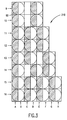
- Figure 5 is an altered pixel image according to an embodiment of the present invention;
- Figure 6 is an embodiment of mapped pixels corresponding to ink drops in embodiments of the present invention;
- Figure 7 is a schematic view of an ink jet printing system; and
- Figure 8 is a flowchart describing an embodiment of the present invention for examining a swath of pixels.
- Figure 7 shows a carriage-type ink
jet printing device 20. A linear array of droplet-producing channels is housed in the printhead 22 of areciprocal carriage assembly 24.Ink droplets 26 are propelled to a receivingmedium 28 that is stepped by a motor 30 a preselected distance in the direction ofarrow 32 each time the printhead 22 traverses across the receivingmedium 28 in the direction indicated byarrow 32. The receivingmedium 28, such as paper, can be stored on thesupply roll 34 and stacked onto a take-up roll 36 by astepper motor 30 or other means well known in the art. - The printhead 22 is fixedly mounted on the
support base 38, which is adapted for reciprocal movement using any well known means such as the two parallel guide rails 40. The reciprocal movement of the printhead 22 may be achieved by acable 42 and a pair ofrotatable pulleys 44, one of which is powered by areversible motor 46. The printhead 22 is generally moved across the receivingmedium 28 perpendicularly to the direction the receivingmedium 28 is moved by themotor 30. Of course, other structures for reciprocating thecarriage assembly 24 are also known within the art. - The printhead 22 may also be connected to a
controller 50 that will be used with embodiments of the present invention to receive a pixel image at a resolution greater than that of the printhead 22. For example, the received pixel image may be a 300x600 dpi image while the printhead has a 300 dpi resolution. Other resolutions are also within the scope of this invention. Thecontroller 50 may include hardware or software to carry out the present invention as will be described below. Further, it is understood that the above description of the inkjet printing device 20 is merely illustrative and is not limiting. That is, other structures are also within the scope of this invention. - Figure 4 shows a flowchart describing an embodiment of the present invention that will be described with respect to Figures 5 and 6. Initially a
pixel image 200 is received in thecontroller 50 instep 100. The image may be created from a scanning device, a ROS, a computer or other similar devices. For illustration purposes, the image that is received is thepixel image 200 shown in Figure 1. In step 102, each of the pixel rows is appropriately numbered and labeled as either an odd or even row. For example,rows rows - In
step 104, the even-numbered pixels in each contiguous block of ON pixels are turned OFF for each of theodd rows row 11, the pixels 11B, 11D and 11F are turned OFF. Further, inrow 13 the pixels 13B, 13D and 13F are also turned OFF. Therefore,step 104 operates without respect to the right-hand edge unlike the method described in US-A-5,270,728. In one embodiment, the left-most pixel 9A is first maintained ON. Then, the second pixel 9B is examined. If the pixel to its immediate left (9A) is maintained ON then the current pixel 9B is turned OFF. The third pixel 9C is then examined by looking at the pixel to its immediate left (9B). Because the pixel to the immediate left (9B) is OFF, the current pixel is maintained ON. - Thus, if the row is an odd-numbered row, operation proceeds from left to right (i.e., in the raster scan direction) to identify a current pixel as an ON pixel if and only if the pixel to the left of the current pixel is OFF. The pixel to the left may be OFF in the original bitmap or it may have been turned OFF during the previous step. Thus, a pixel from the original bitmap is not identified as an ON pixel unless the pixel to its immediate left is OFF.
- In step 106, the even-numbered pixels for each of the
even rows pixel row 12. Accordingly, pixel 12E, 12C and 12A are turned OFF forpixel row 12. Inpixel row 14, pixel 14G is the right-most pixel and accordingly pixels 14F, 14D and 14B are turned OFF. Therefore, each pixel corresponding to the right edge (in an even-numbered row) is maintained ON without regard to the left-hand edge of the respective pixel row. - Thus, if the row is an even-numbered row, operation proceeds from right to left (opposite to the raster scan direction) to identify a current pixel as an ON pixel if and only if the pixel to the right of the current pixel is OFF. The pixel to the right may be OFF from the original bitmap or it may have been turned OFF during the previous step. Thus, a pixel from the original bitmap is not identified as an ON pixel unless the pixel to its immediate right is OFF.
- Finally, in
step 108, the remaining ON pixels within the alteredimage 220 are appropriately printed using the printhead 22 having a lesser resolution than that of theoriginal pixel image 200. Preferably, the printhead has a 300 dpi (12 dots/mm) resolution while thepixel image 200 is a 300 dpi x 600 dpi (12 x 24 dots/mm) image. - Figure 6 shows each remaining ON pixel in the altered
image 220 being mapped to adot 60 corresponding to a 300 dpi ink droplet. For example, each ON pixel of the alteredimage 220 is mapped with an OFF pixel to its immediate right. Accordingly, thealtered image 220 within thecontroller 50 is raster scanned so as to produce thedots 60 on the receivingmedium 28 so as to visibly reproduce thepixel image 200 at the printhead's resolution. The mapping can result in "enlarging" the image as the last dots inrows original pixel image 200. - Accordingly, the above-described method does not require as complicated an algorithm as that described in US-A-5,270,728. Furthermore, the present invention avoids problems of the prior art that require the algorithm to always be sensitive to both the left and right hand edges (i.e., the edge proximity).
- The above-described method is preferably carried out in the
controller 50 by use of software on a host computer where the bits of each scan line are considered serially. That is, each of the odd-numbered rows is examined in a left-to-right manner while each of the even-numbered rows are examined in a right-to-left manner. In so doing, a state bit may be retained to record the state of the last pixel. Thus, if a white pixel is encountered, the state bit may be set to white. However, if a black pixel is encountered, the pixel is set to white if and only if the state variable is black. The state variable is then set to whatever the pixel was set to. - The invention may be practiced in software, as described above, or in hardware, as will be described below. An inkjet printer with a reciprocating printhead 22 normally has some number (typically 48 or more) of jets or channels that are configured in an orientation perpendicular to the direction of travel of the printhead 22. All of these jets or channels can fire essentially simultaneously to produce a vertical column of pixels at each location. In this way, as the printhead 22 traverses the width of the receiving
medium 28, an entire swath of pixels is printed. Each swath is a set of pixels the width of the receivingmedium 28 and the height of the printhead 22. Because firing of the jets or channels must be precisely timed, a dedicated memory buffer (also referred to as the swath buffer) is used within thecontroller 50 to store the image data for an entire swath prior to the traverse of the printhead 22 across the receivingmedium 28. The invention operates on the data in the swath buffer prior to its transmission to the printhead 22. - Hardware operation can turn a pixel OFF if the previous pixel is ON. This operation is a logical AND with the complement of the previous pixel. Because of the bidirectional nature of the printhead 22, two or more passes are preferably made over the swath buffer, with half of the passes being in the left to right direction, and the other half of the passes being in the right to left direction. Each pass treats some number (up to half) of the scanlines in the swath buffer in parallel. Preferably only two passes are needed, one in a left to right direction, processing the odd-numbered rows in parallel, and one in a right to left direction, processing the even-numbered rows in parallel. Embodiments in which a larger number of passes is used to process sub-sections of a swath are also within the scope of this invention.
- A left to right pass is described with respect to Figure 8. A counter N representative of the number of consecutive ON pixels is set to one in step 130. Thus, the counter N is not set to 1 until the first ON pixel (i.e., the leftmost) is encountered for a respective row. Further, each row is individually processed with respect to that respective row even though all of the odd-numbered rows are being processed simultaneously (i.e., in parallel). Thus, each row will include its own counter N. However, for ease of illustration, the processing will be described with respect to one counter N. In step 132, a current column is input as the leftmost column in the swath for the odd-numbered rows. In step 134, a decision is made whether the current column is the leftmost in the swath based on the counter N. If so, then the current column is printed by the printhead 22 in step 135. The current column is logically inverted in step 136. The NEXT column in the swath for the odd-numbered rows is then obtained in step 138 and the counter N is incremented in
step 140. In step 142, a logical AND occurs between the inverted scan column (from step 136) and the next column (from step 138). The logical AND result is sent to the printhead 22 in step 144. Operation continues by returning to step 134. - A right to left pass occurs in a similar manner to that of Figure 8. However, in a right to left pass, the current column that is input in step 132 is the rightmost column in the swath for the even-numbered rows. Step 134 decides whether the current column is the rightmost ON pixel in the swath. Operation continues in a similar manner except the NEXT column in step 133 proceeds in a right to left manner.
Claims (10)
- A method of printing an image having a defined resolution along a given axis using an ink jet printer having a predetermined resolution along the given axis less than the defined resolution of the image, the image comprising a first pixel row of consecutively numbered ON pixels extending along the given axis from a first left edge pixel to a first right edge pixel and a second pixel row of consecutively numbered ON pixels extending along the given axis from a second right edge pixel to a second left edge pixel, the method comprising the steps of:(a) receiving the image having the defined resolution along the given axis;(b) turning OFF even numbered pixels from the first pixel row;(c) turning OFF even numbered pixels from the second pixel row; and(d) after steps (b) and (c), printing marks at areas corresponding to remaining ON pixels in the first pixel row and remaining ON pixels in the second pixel row, the marks visibly reproducing the image at the defined resolution along the given axis.
- The method of claim 1, wherein the first pixel row and the second pixel row each comprise at least four pixels.
- The method of claim 1 or 2, further comprising the steps of:turning OFF even numbered pixels from subsequently odd-numbered pixel rows, each subsequently odd-numbered pixel row having consecutively numbered ON pixels extending along the given axis from a corresponding left edge pixel to a corresponding right edge pixel; andfiring ink drops from the ink jet printer at areas corresponding to remaining ON pixels in said subsequently odd-numbered pixel rows.
- The method of claim 3, further comprising the steps of:turning OFF even numbered pixels from subsequently even-numbered pixel rows, each subsequently even-numbered pixel row having consecutively numbered ON pixels extending along the given axis from a corresponding right edge pixel to a corresponding left edge pixel; andfiring ink drops from the ink jet printer at areas corresponding to remaining ON pixels in said subsequently even numbered pixel rows.
- The method of any of claims 1 to 4, wherein step (b) comprises the steps of: (b1) starting with a left-most pixel in the first pixel row, determining whether a pixel to the immediate left of a current pixel is ON, wherein the current pixel is turned OFF when the pixel to the immediate left of the current pixel is ON, said turned OFF pixel thereafter being an OFF pixel; and (b2) repeating the determining step for each subsequent pixel of the first pixel row, and/or step (c) comprises the steps of: (c1) starting with a right-most pixel in the second pixel row, determining whether a pixel to the immediate right of a current pixel is ON, wherein the current pixel is turned OFF when the pixel to the immediate right of the current pixel is ON, said turned OFF pixel thereafter being an OFF pixel; and (c2) repeating the determining step for each subsequent pixel of the second pixel row.
- A method for use with a printer having a predetermined resolution along a first direction, the method comprising the steps of:receiving a pixel image having a defined resolution in the first direction, the pixel image comprising a first pixel row extending in the first direction from a first ON edge pixel to a second ON edge pixel and a second pixel row extending in a direction opposite to the first direction from a third ON edge pixel to a fourth ON edge pixel, the first pixel row and the second pixel row each having at least four consecutive ON pixels;altering the first pixel row by turning OFF selected pixels and by maintaining ON selected pixels, the altered first pixel row having no adjacent ON selected pixels and no adjacent OFF selected pixels, the first ON edge pixel maintained as one of the ON selected pixels;altering the second pixel row by turning OFF selected pixels and by maintaining ON selected pixels, the altered second pixel row having no adjacent ON selected pixels and no adjacent OFF selected pixels, the third ON edge pixel maintained as one of the ON selected pixels; andraster scanning the altered first pixel row and the altered second pixel row with the printer to visibly reproduce the image at the defined resolution.
- A printing method comprising the steps of:receiving a pixel image having a defined resolution along a given axis, the pixel image comprising a first pixel row extending along the given axis from a first edge pixel to a second edge pixel and a second pixel row extending in a direction opposite to the first direction from a third edge pixel to a fourth edge pixel, the first pixel row and the second pixel row each having at least four consecutive ON pixels;selectively examining each pixel in the first pixel row, starting with the first edge pixel, to alternately label each pixel as one of an odd-numbered pixel and an even-numbered pixel, the first edge pixel being labeled as the odd-numbered pixel;selectively examining each pixel in the second pixel row, starting with the third edge pixel, to alternately label each pixel as one of an odd-numbered pixel and an even-numbered pixel, the third edge pixel being labeled as the odd-numbered pixel; andprinting each pixel labeled as an odd-numbered pixel with a printer having a lesser resolution along the given axis than the defined resolution to visibly reproduce the image at the defined resolution.
- A printing method comprising the steps of:receiving a pixel image having a defined resolution along a given axis, the pixel image comprising a first pixel row extending along the given axis from a first edge pixel to a second edge pixel and a second pixel row extending in a direction opposite to the first direction from a third edge pixel to a fourth edge pixel;altering the pixel image to produce an altered pixel image, the altering step comprising the steps of:maintaining ON the first edge pixel of the first pixel row;turning OFF selected pixels and maintaining ON selected pixels of the first pixel row by examining each pixel, in consecutive order, from the first edge pixel to the second edge pixel, pixels being selected OFF only when an immediately previously examined pixel is maintained ON;maintaining ON the third edge pixel of the second pixel row; andturning OFF selected pixels and maintaining ON selected pixels of the second pixel row by examining each pixel, in consecutive order, from the third edge pixel to the fourth edge pixel, pixels of the second pixel row being selected OFF only when an immediately previously examined pixel is maintained ON, the altered pixel image being represented by the maintained ON selected pixels; andraster scanning the altered pixel image with a printer having a resolution less than the defined resolution to visibly reproduce the pixel image at the defined resolution.
- A method of printing an image with a printer, the image having a resolution along a given axis greater than a resolution of the printer, the method comprising the steps of:receiving the image comprising a plurality of pixel rows each having at least four pixels extending from a first edge of the image to a second edge of the image;altering a first pixel row to produce an altered pixel row having no adjacent ON pixels and no adjacent OFF pixels, wherein the pixel corresponding to the first edge of the first pixel row is not altered during the first pixel row altering step;altering a second pixel row to produce an altered second pixel row having no adjacent ON pixels and no adjacent OFF pixels, wherein the pixel corresponding to the second edge of the second pixel row is not altered during the second pixel row altering step; andprinting the altered first pixel row and the altered second pixel row with the ink jet printer to visibly reproduce the image at the resolution of the image.
- A programmable image processing apparatus when suitably programmed for carrying out the method of any of the preceding claims.
Applications Claiming Priority (2)
| Application Number | Priority Date | Filing Date | Title |
|---|---|---|---|
| US368137 | 1995-01-03 | ||
| US08/368,137 US5767870A (en) | 1995-01-03 | 1995-01-03 | Edge insensitive pixel deletion method for printing high resolution image |
Publications (3)
| Publication Number | Publication Date |
|---|---|
| EP0720918A2 true EP0720918A2 (en) | 1996-07-10 |
| EP0720918A3 EP0720918A3 (en) | 1997-11-05 |
| EP0720918B1 EP0720918B1 (en) | 2002-05-08 |
Family
ID=23449997
Family Applications (1)
| Application Number | Title | Priority Date | Filing Date |
|---|---|---|---|
| EP96300072A Expired - Lifetime EP0720918B1 (en) | 1995-01-03 | 1996-01-03 | Edge insensitive pixel deletion method for printing high resolution image |
Country Status (4)
| Country | Link |
|---|---|
| US (1) | US5767870A (en) |
| EP (1) | EP0720918B1 (en) |
| JP (1) | JPH08230241A (en) |
| DE (1) | DE69621054T2 (en) |
Cited By (1)
| Publication number | Priority date | Publication date | Assignee | Title |
|---|---|---|---|---|
| CN112164014A (en) * | 2020-10-15 | 2021-01-01 | 江西威力固智能设备有限公司 | Layer processing method and spray printing equipment |
Families Citing this family (8)
| Publication number | Priority date | Publication date | Assignee | Title |
|---|---|---|---|---|
| US6049393A (en) * | 1997-11-19 | 2000-04-11 | Tektronix, Inc. | Method for enhancing resolution in a printed image |
| DE19905540A1 (en) * | 1999-02-10 | 2000-08-17 | Zahnradfabrik Friedrichshafen | Electrical machine |
| US6318832B1 (en) | 2000-03-24 | 2001-11-20 | Lexmark International, Inc. | High resolution printing |
| US6592203B1 (en) * | 2002-02-11 | 2003-07-15 | Lexmark International, Inc. | Subcovered printing mode for a printhead with multiple sized ejectors |
| US7059698B1 (en) | 2002-10-04 | 2006-06-13 | Lexmark International, Inc. | Method of altering an effective print resolution of an ink jet printer |
| ZA200704041B (en) * | 2004-11-24 | 2009-03-25 | Thomson Licensing | Film grain simulation technique for use in media playback devices |
| US9299196B2 (en) * | 2004-12-22 | 2016-03-29 | Pitney Bowes Inc. | Method and system for high speed printing using drop-on demand technology that compensates for droplet satellites |
| JP2010217691A (en) * | 2009-03-18 | 2010-09-30 | Fuji Xerox Co Ltd | Image forming apparatus, image processor, and program |
Citations (2)
| Publication number | Priority date | Publication date | Assignee | Title |
|---|---|---|---|---|
| US4774530A (en) | 1987-11-02 | 1988-09-27 | Xerox Corporation | Ink jet printhead |
| US5270728A (en) | 1991-04-17 | 1993-12-14 | Hewlett-Packard Company | Raster imaging device speed-resolution product multiplying method and resulting pixel image data structure |
Family Cites Families (14)
| Publication number | Priority date | Publication date | Assignee | Title |
|---|---|---|---|---|
| US4437122A (en) * | 1981-09-12 | 1984-03-13 | Xerox Corporation | Low resolution raster images |
| JPS60116464A (en) * | 1983-11-30 | 1985-06-22 | Toshiba Corp | Printer |
| JP2707259B2 (en) * | 1987-11-05 | 1998-01-28 | キヤノン株式会社 | Ink jet recording device |
| DE3925913A1 (en) * | 1989-08-04 | 1991-02-07 | Siemens Ag | METHOD FOR DRIVING PRINTING ELEMENTS |
| US4967203A (en) * | 1989-09-29 | 1990-10-30 | Hewlett-Packard Company | Interlace printing process |
| US5353387A (en) * | 1990-09-10 | 1994-10-04 | Mannesmann Aktiengesellschaft | Process for reducing the quantity of ink applied to recording substrates by ink printing devices to prevent image degradation |
| US5029108A (en) * | 1990-09-24 | 1991-07-02 | Destiny Technology Corporation | Edge enhancement method and apparatus for dot matrix devices |
| JP2986124B2 (en) * | 1991-06-14 | 1999-12-06 | キヤノン株式会社 | Ink jet recording device |
| US5574832A (en) * | 1992-08-03 | 1996-11-12 | Hewlett-Packard Corporation | Double axis dot depletion for 600 DPI edge acuity with 300 DPI print cartridge |
| US5469198A (en) * | 1992-08-03 | 1995-11-21 | Hewlett-Packard Company | Multiple pass printing for achieving increased print resolution |
| DE69432964T2 (en) * | 1993-05-03 | 2004-06-03 | Hewlett-Packard Co. (N.D.Ges.D.Staates Delaware), Palo Alto | Increased print resolution in the carriage axis of an inkjet printer |
| US5480240A (en) * | 1993-12-01 | 1996-01-02 | Lexmark International, Inc. | Print quality enhancement method and apparatus |
| US5719601A (en) * | 1995-01-03 | 1998-02-17 | Xerox Corporation | Intentional underthinning of 600×300 image data when printing in multi-pass mode |
| US5677714A (en) * | 1995-01-03 | 1997-10-14 | Xerox Corporation | Neighbor insentive pixel deletion method for printing high resolution image |
-
1995
- 1995-01-03 US US08/368,137 patent/US5767870A/en not_active Expired - Lifetime
- 1995-12-26 JP JP7338886A patent/JPH08230241A/en not_active Withdrawn
-
1996
- 1996-01-03 EP EP96300072A patent/EP0720918B1/en not_active Expired - Lifetime
- 1996-01-03 DE DE69621054T patent/DE69621054T2/en not_active Expired - Lifetime
Patent Citations (2)
| Publication number | Priority date | Publication date | Assignee | Title |
|---|---|---|---|---|
| US4774530A (en) | 1987-11-02 | 1988-09-27 | Xerox Corporation | Ink jet printhead |
| US5270728A (en) | 1991-04-17 | 1993-12-14 | Hewlett-Packard Company | Raster imaging device speed-resolution product multiplying method and resulting pixel image data structure |
Cited By (2)
| Publication number | Priority date | Publication date | Assignee | Title |
|---|---|---|---|---|
| CN112164014A (en) * | 2020-10-15 | 2021-01-01 | 江西威力固智能设备有限公司 | Layer processing method and spray printing equipment |
| CN112164014B (en) * | 2020-10-15 | 2024-04-09 | 江西威力固智能设备有限公司 | Layer processing method and jet printing equipment |
Also Published As
| Publication number | Publication date |
|---|---|
| EP0720918A3 (en) | 1997-11-05 |
| DE69621054D1 (en) | 2002-06-13 |
| DE69621054T2 (en) | 2002-09-26 |
| US5767870A (en) | 1998-06-16 |
| EP0720918B1 (en) | 2002-05-08 |
| JPH08230241A (en) | 1996-09-10 |
Similar Documents
| Publication | Publication Date | Title |
|---|---|---|
| EP0720919B1 (en) | Resolution enhancement and thinning method for printing pixel images | |
| US5270728A (en) | Raster imaging device speed-resolution product multiplying method and resulting pixel image data structure | |
| US4920355A (en) | Interlace method for scanning print head systems | |
| JP3356499B2 (en) | Row printing method for pixel array | |
| EP0575057B1 (en) | Bidirectional ink jet printing | |
| EP0730973A2 (en) | Recording apparatus and method | |
| US6540315B1 (en) | Systems and methods for stitching overlapping swaths | |
| KR930012302A (en) | Ink jet recording method and apparatus | |
| JPH08244256A (en) | Transition method between print modes | |
| EP0720911B1 (en) | Neighbor insensitive pixel deletion method for printing high resolution image | |
| EP0720918B1 (en) | Edge insensitive pixel deletion method for printing high resolution image | |
| US5719601A (en) | Intentional underthinning of 600×300 image data when printing in multi-pass mode | |
| US6069709A (en) | Bi-directional printing with overlap using both breaks and transition regions | |
| JPH1034935A (en) | Dot adhesion control method of liquid ink printer | |
| JPH09164706A (en) | Ink jet head | |
| JPS62249748A (en) | Method of calming operation of dot printer | |
| EP0978799B1 (en) | Data processing method, data processing apparatus and image printing apparatus | |
| US6406111B1 (en) | Method of increasing the resolution of an ink jet printer | |
| EP0749841B1 (en) | Recorder and print control method | |
| US7093925B2 (en) | Method and device for printing with a uniform printing medium transport distance | |
| JP3426659B2 (en) | Method for reducing pixel density along multiple axes of a multidimensional image | |
| JP2000052597A (en) | Print controller | |
| JPS60143988A (en) | Underline-printing method for dot printer | |
| JP2692203B2 (en) | Printer | |
| JPH0948110A (en) | Image recording apparatus |
Legal Events
| Date | Code | Title | Description |
|---|---|---|---|
| PUAI | Public reference made under article 153(3) epc to a published international application that has entered the european phase |
Free format text: ORIGINAL CODE: 0009012 |
|
| AK | Designated contracting states |
Kind code of ref document: A2 Designated state(s): DE FR GB |
|
| PUAL | Search report despatched |
Free format text: ORIGINAL CODE: 0009013 |
|
| AK | Designated contracting states |
Kind code of ref document: A3 Designated state(s): DE FR GB |
|
| 17P | Request for examination filed |
Effective date: 19980506 |
|
| 17Q | First examination report despatched |
Effective date: 19990202 |
|
| GRAG | Despatch of communication of intention to grant |
Free format text: ORIGINAL CODE: EPIDOS AGRA |
|
| GRAG | Despatch of communication of intention to grant |
Free format text: ORIGINAL CODE: EPIDOS AGRA |
|
| GRAH | Despatch of communication of intention to grant a patent |
Free format text: ORIGINAL CODE: EPIDOS IGRA |
|
| GRAH | Despatch of communication of intention to grant a patent |
Free format text: ORIGINAL CODE: EPIDOS IGRA |
|
| REG | Reference to a national code |
Ref country code: GB Ref legal event code: IF02 |
|
| GRAA | (expected) grant |
Free format text: ORIGINAL CODE: 0009210 |
|
| AK | Designated contracting states |
Kind code of ref document: B1 Designated state(s): DE FR GB |
|
| REF | Corresponds to: |
Ref document number: 69621054 Country of ref document: DE Date of ref document: 20020613 |
|
| ET | Fr: translation filed | ||
| PLBE | No opposition filed within time limit |
Free format text: ORIGINAL CODE: 0009261 |
|
| STAA | Information on the status of an ep patent application or granted ep patent |
Free format text: STATUS: NO OPPOSITION FILED WITHIN TIME LIMIT |
|
| 26N | No opposition filed |
Effective date: 20030211 |
|
| PGFP | Annual fee paid to national office [announced via postgrant information from national office to epo] |
Ref country code: DE Payment date: 20101230 Year of fee payment: 16 |
|
| PG25 | Lapsed in a contracting state [announced via postgrant information from national office to epo] |
Ref country code: DE Free format text: LAPSE BECAUSE OF NON-PAYMENT OF DUE FEES Effective date: 20120801 |
|
| REG | Reference to a national code |
Ref country code: DE Ref legal event code: R119 Ref document number: 69621054 Country of ref document: DE Effective date: 20120801 |
|
| PGFP | Annual fee paid to national office [announced via postgrant information from national office to epo] |
Ref country code: GB Payment date: 20131223 Year of fee payment: 19 |
|
| PGFP | Annual fee paid to national office [announced via postgrant information from national office to epo] |
Ref country code: FR Payment date: 20140120 Year of fee payment: 19 |
|
| GBPC | Gb: european patent ceased through non-payment of renewal fee |
Effective date: 20150103 |
|
| PG25 | Lapsed in a contracting state [announced via postgrant information from national office to epo] |
Ref country code: GB Free format text: LAPSE BECAUSE OF NON-PAYMENT OF DUE FEES Effective date: 20150103 |
|
| REG | Reference to a national code |
Ref country code: FR Ref legal event code: ST Effective date: 20150930 |
|
| PG25 | Lapsed in a contracting state [announced via postgrant information from national office to epo] |
Ref country code: FR Free format text: LAPSE BECAUSE OF NON-PAYMENT OF DUE FEES Effective date: 20150202 |