EP0720919A1 - Resolution enhancement and thinning method for printing pixel images - Google Patents
Resolution enhancement and thinning method for printing pixel images Download PDFInfo
- Publication number
- EP0720919A1 EP0720919A1 EP96300048A EP96300048A EP0720919A1 EP 0720919 A1 EP0720919 A1 EP 0720919A1 EP 96300048 A EP96300048 A EP 96300048A EP 96300048 A EP96300048 A EP 96300048A EP 0720919 A1 EP0720919 A1 EP 0720919A1
- Authority
- EP
- European Patent Office
- Prior art keywords
- pixel image
- resolution
- pixels
- pixel
- image
- Prior art date
- Legal status (The legal status is an assumption and is not a legal conclusion. Google has not performed a legal analysis and makes no representation as to the accuracy of the status listed.)
- Granted
Links
- 238000000034 method Methods 0.000 title claims abstract description 34
- 238000007639 printing Methods 0.000 title claims description 10
- 230000001965 increasing effect Effects 0.000 claims description 18
- 238000010304 firing Methods 0.000 claims description 2
- 230000002708 enhancing effect Effects 0.000 abstract description 5
- 230000007704 transition Effects 0.000 description 23
- 230000000007 visual effect Effects 0.000 description 5
- 238000012360 testing method Methods 0.000 description 4
- 238000007641 inkjet printing Methods 0.000 description 3
- 230000007547 defect Effects 0.000 description 1
- 238000012217 deletion Methods 0.000 description 1
- 230000037430 deletion Effects 0.000 description 1
- 230000000694 effects Effects 0.000 description 1
- 238000010438 heat treatment Methods 0.000 description 1
- 210000004072 lung Anatomy 0.000 description 1
- 230000003252 repetitive effect Effects 0.000 description 1
- 230000000717 retained effect Effects 0.000 description 1
- 230000002441 reversible effect Effects 0.000 description 1
- 230000008016 vaporization Effects 0.000 description 1
- 238000009834 vaporization Methods 0.000 description 1
Images


Classifications
-
- G—PHYSICS
- G06—COMPUTING; CALCULATING OR COUNTING
- G06K—GRAPHICAL DATA READING; PRESENTATION OF DATA; RECORD CARRIERS; HANDLING RECORD CARRIERS
- G06K15/00—Arrangements for producing a permanent visual presentation of the output data, e.g. computer output printers
- G06K15/02—Arrangements for producing a permanent visual presentation of the output data, e.g. computer output printers using printers
- G06K15/10—Arrangements for producing a permanent visual presentation of the output data, e.g. computer output printers using printers by matrix printers
- G06K15/102—Arrangements for producing a permanent visual presentation of the output data, e.g. computer output printers using printers by matrix printers using ink jet print heads
-
- B—PERFORMING OPERATIONS; TRANSPORTING
- B41—PRINTING; LINING MACHINES; TYPEWRITERS; STAMPS
- B41J—TYPEWRITERS; SELECTIVE PRINTING MECHANISMS, i.e. MECHANISMS PRINTING OTHERWISE THAN FROM A FORME; CORRECTION OF TYPOGRAPHICAL ERRORS
- B41J2/00—Typewriters or selective printing mechanisms characterised by the printing or marking process for which they are designed
- B41J2/485—Typewriters or selective printing mechanisms characterised by the printing or marking process for which they are designed characterised by the process of building-up characters or image elements applicable to two or more kinds of printing or marking processes
- B41J2/505—Typewriters or selective printing mechanisms characterised by the printing or marking process for which they are designed characterised by the process of building-up characters or image elements applicable to two or more kinds of printing or marking processes from an assembly of identical printing elements
- B41J2/5056—Typewriters or selective printing mechanisms characterised by the printing or marking process for which they are designed characterised by the process of building-up characters or image elements applicable to two or more kinds of printing or marking processes from an assembly of identical printing elements using dot arrays providing selective dot disposition modes, e.g. different dot densities for high speed and high-quality printing, array line selections for multi-pass printing, or dot shifts for character inclination
- B41J2/5058—Typewriters or selective printing mechanisms characterised by the printing or marking process for which they are designed characterised by the process of building-up characters or image elements applicable to two or more kinds of printing or marking processes from an assembly of identical printing elements using dot arrays providing selective dot disposition modes, e.g. different dot densities for high speed and high-quality printing, array line selections for multi-pass printing, or dot shifts for character inclination locally, i.e. for single dots or for small areas of a character
Definitions
- This invention relates to ink jet printers and more particularly, to a method of achieving efficiency by utilizing resolution enhancement with pixel deletion.
- An ink jet printhead selectively ejects droplets of ink from a plurality of drop ejectors to create a desired image on an image receiving medium, such as paper.
- the printhead typically comprises an array of drop ejectors that convey ink to the image receiving medium.
- the printhead moves back and forth relative to the image receiving medium to print the images in swaths.
- the ink jet printhead typically comprises a plurality of ink passageways, such as capillary channels.
- Each channel has a nozzle end and is connected to an ink supply manifold. Ink from the manifold is retained within each channel, until in response to an appropriate signal applied to a resistive element in that channel, the ink in a portion of the channel adjacent to the heating element is rapidly heated and vaporized. Rapid vaporization of some of the ink from the channel creates a bubble that causes a quantity of ink (i.e., an ink droplet) to be ejected through the nozzle to the image receiving medium.
- U.S. Patent No. 4,774,530 to Hawkins shows a general configuration of a typical ink jet printer.
- ink jet printers have a 300 dots per inch (dpi) resolution (approximately 12 dots per mm) along the horizontal axis (also called the raster scan axis) and a 300 dpi vertical resolution so as to form round individual ink droplets that form the pixel images on the paper. These ink jet printers are therefore designed to print 300 x 300 dpi output images. However, increased resolution is desired to print higher resolution images and thus visually pleasing images. For example, it may be desirable to print a pixel image at a 300 x 600 dpi effective resolution (approximately 12x24 dots per mm) using a 300 dpi ink jet printhead. This resulting image would therefore appear to be printed with a higher resolution.
- dpi dots per inch
- US-A-5,270,728 to Lund et al. discloses a method of multiplying the speed resolution of a raster scanning device such as an ink jet printer.
- a 300 x 600 dpi pixel image is mapped to a corresponding, nonoverlapping physical dot image and the ink jets are fired in response to the dot image to direct ink droplets onto the printer at a 600 dpi resolution grid timing to effectively double the horizontal resolution of the pixel image.
- US-A-5,270,728 describes thinning the pixel image before it is printed by selectively turning off pixels within the pixel image by referencing the edges of the pixel image. More specifically, US-A-5,270,728 describes a method of maintaining selected ones of the pixels in an ON state based on the ON pixel adjacency and edge proximity criteria. In US-A-5,270,728, the pixel image that is initially received is a 300 x 600 dpi image. The described method thins the pixel image so as to print at the resolution of the printhead.
- US-A-5,029,108 to Lung teaches a method of enhancing edge representations when an image is converted from graphical format to print format. Edges are modified by repositioning related dots or by altering the dot size. A TBAP (To Be Adjusted Pixel) located on an edge is modified to enhance the smoothness of a segment transition. Gradient mask matrices are used to determine whether a change of brightness occurs.
- a pixel pattern is formed including a center pixel and neighboring pixels.
- the pixel pattern is compared with standard pixel patterns and the center pixel is altered or not based on the standard pixel pattern that the current pixel pattern matches.
- this invention provides a method of resolution enhancement in accordance with the accompanying claims.
- the invention provides a method of resolution enhancement and thinning by altering a 300 x 300 dpi image to visually appear as a 300 x 600 dpi pixel image on the image receiving medium.
- Other resolutions such as 400 and 800 dpi (approximately 16 and 32 dots per mm) are also within the scope of this invention.
- This invention provides a method for printing a pixel image using an ink jet printer having a defined resolution along a raster scan axis.
- the pixel image is received having the defined resolution.
- a resolution (or density) of the pixel image is increased along the raster scan axis.
- the pixel image is then thinned and subsequently the thinned pixel image is raster scanned with the ink jet printer to visibly reproduce the pixel image at the increased resolution.
- the pixel image is preferably thinned using a checkerboard pattern for all interior pixels while maintaining edge pixels.
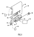
- Figure 1 shows a carriage-type ink jet printing device 30.
- a linear array of droplet-producing channels is housed in the printhead 34 of a reciprocating carriage assembly 36.
- Ink droplets 38 are propelled to a receiving medium 40 that is stepped by a motor 42 a preselected distance in the direction of arrow 44 each time the printhead 34 traverses across the receiving medium 40 in the direction indicated by arrows 46.
- the receiving medium 40 such as paper, can be stored on a supply roll 48 and stacked onto a takeup roll 50 by the motor 42 or other means well known in the art.
- the printhead 34 is fixedly mounted on a support base 52, which is adapted for reciprocal movement using any well known means such as the two parallel guide rails 54.
- the reciprocal movement of the printhead 34 may be achieved by a cable 56 and a pair of rotatable pulleys 58, one of which is powered by a reversible motor 62.
- the printhead 34 is generally moved across the receiving medium 40 perpendicular to the direction the receiving medium is moved by the motor 42.
- other structures of reciprocating the carriage assembly 36 are also known within the art.
- the present invention will be described with respect to receiving a 300 x 300 dpi pixel image and subsequently altering the pixel image to output an image with a visual appearance of a 300 x 600 dpi resolution.
- the printhead 34 is preferably adapted to print ink drops at a 300 dpi resolution. Therefore, the method described below preferably gives the appearance that a 300 dpi printhead is printing at a 300 x 600 dpi effective resolution.
- the resolutions discussed herein are merely illustrative and are not intended to be limiting. That is, other resolutions are also within the scope of this invention.
- FIG. 2 shows a flowchart describing an embodiment of the present invention that will be described with respect to Figs. 3A-3D.
- a 300 x 300 dpi pixel image is received within the controller 60.
- the image may be created from a scanning device, a ROS, a computer or other similar device.
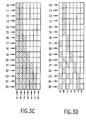
- Figure 3A shows a pixel image having ON pixels represented by shaded boxes and OFF pixels represented by unshaded boxes.
- each pixel is represented by a corresponding box (or rectangle) having a 300 dpi vertical and horizontal resolution.
- each row is consecutively numbered as one of the pixel rows 10-25.
- Each of the columns is labelled with a corresponding letter A', B' and C'.
- the columns are consecutively labelled across the raster scanning axis while the rows are consecutively labelled in the slow scan (or vertical) direction.
- the pixel in the upper left hand corner is labelled as pixel 10A'.
- the ON pixel in the bottom right hand corner of the image is labelled as pixel 25C'.
- a 300 x 600 dpi pixel image is created from the 300 x 300 dpi pixel image (shown in Figure 3A).
- each 300 dpi pixel from Figure 3A is converted into two 300 x 600 dpi pixels as shown in Figure 3B.
- pixel 10A' is converted into pixels 10A and 10B while pixel 25C' is converted into pixels 25E and 25F. In essence, this doubles the number of pixels within the pixel image.
- step 102 effectively doubles the resolution or density of pixels within the image. It is understood that step 102 is not limited to doubling the resolution but rather any increase in the resolution or density is within the scope of this invention.
- the pixel rows 17 and 18 differ from each other along the edge of the image while the pixels rows 21 and 22 differ from each other along the edge of the image. This may cause a jagged or staircase image if printed using the pixel image in Figure 3B.
- the present invention preferably alters pixel rows along the edges so as to better conform with a 300 x 600 dpi image and thus remove the jagged edges.
- rows 10-17 each correspond to a black, black, white, white pattern (hereafter a BBWW pattern) along the edge of the image.
- Row 18 shows a black, black, black, black pattern (a BBBB pattern) for the same columns along the edge of the image.
- a toggling algorithm may be used to alter pixels along the edges when adjacent pixel rows differ from each other.
- the number of bits to toggle is one quarter of the number of identical rows that are different from the current row. That is, a first row is considered to be identical to a second row if all of the pixels in a small window under consideration in the first row are identical to the corresponding pixels in the window at the same location on the second row.
- a maximum of four bits may be toggled in a respective column.
- rows 10-17 of Figure 3B represent eight pixel rows that are different from pixel row 18.
- Toggling also may occur in columns E and F because of the difference between pixel rows 19-21 and 22-25.
- pixel rows 19, 20 and 21 have a black pixel in column D and a white pixel in column E (i.e., a BBWW pattern). Because these three rows differ from row 22, one bit (21E) will be toggled ON in Figure 3C.
- rows 22, 23, 24 and 25 each have an ON pixel in column F. Therefore, one bit (22F) will be turned OFF in column F.
- the toggling operation is performed by examining rows above and below a current row. Toggling is effected based on the number of identical rows that are different from the transition row. The number of rows that are different is divided by four to equal the number of pixels to be toggled. This number may be rounded up for pixel rows above a current row but truncated for pixel rows below the transition row. That is, when examining rows above the transition row, any quotient greater than one half following the division by four indicates another bit to be toggled ON whereas when examining rows below the transition row any quotient after the division by four is ignored for pixels to be turned OFF.
- the edge definition of the pixel image is altered to have a 600 dpi effective resolution. Therefore, the edges of the image are much smoother than the original 300 dpi pixel image of Figure 3A.
- the above toggling description used to enhance the edges is merely illustrative and is not limiting. That is, many different methods of altering the edge regions are also within the scope of this invention.
- the toggled pixel image having the increased resolution (or density) is thinned to create a thinned pixel image such as that in Figure 3D.
- This thinning operation can be achieved in many different manners.
- the edge pixels are maintained on so as to clearly define the edge region. That is, pixels 10B, 11B, 12B, 13B, 14B, 15B, 16C, 17C, 18C, 19D, 20D, 21E, 22E, 23F, 24F, and 25F are all maintained ON in the thinned image.
- Other pixels within the interior of the pixel image are thinned using one of several methods.
- the interior region of the pixel image shown in Figure 3D is thinned based on an underlying checkerboard pattern that results in interior pixels being maintained ON so that ON interior pixels are diagonal to other ON interior pixels and OFF interior pixels are diagonal to other OFF interior pixels.
- This helps avoid visual defects caused by the vertical orientation of ON pixels within the interior region.
- Thinning greatly improves the overall quality of the pixel image because it helps avoid printing with excessive ink on the print sheet.
- the thinning step 106 helps improve the visual quality of the resulting printed image.
- An exemplary checkerboard pattern 90 is shown in Figure 5 to represent an ON/OFF/ON/OFF pattern for odd numbered rows 19, 21, 23 and 25 and an OFF/ON/OFF/ON pattern for even numbered rows 20, 22, 24 and 26.
- This underlying checkerboard pattern 90 (or mask) is preferably the size of a swath of data although Figure 5 only shows eight rows 19-26. 8ased on the respective position of a pixel within the swath, it is determined whether an interior pixel should be maintained ON or turned OFF based on the position of the interior pixel within the checkerboard pattern 90.
- One purpose of the checkerboard pattern is that the interior pixels will be efficiently thinned so that no two ON interior pixels are adjacent to one another either for one row or for adjacent rows.
- pixels 19B, 20A, 20C, 21B, 21D, 22A, 22C, 23B, 23D, 24A, 24C, 24E, 25B and 25D are thinned (as shown in Figure 3D) based on the state of pixels 19B, 20A, 20C, 21B, 21D, 22A, 22C, 23B, 23D, 24A, 24C, 24E, 25B and 25D in the checkerboard pattern 90.
- pixels 11A, 13A, 15A, 16B, 18B, 19C, 22D, 23E and 25E are thinned in order to avoid having a state of two pixels ON in a row.
- the printhead 34 is scanned across the image receiving medium 40 in step 108 to discharge 300 dpi ink droplets based on the thinned pixel image of Figure 3D.
- Figure 3D shows 300 x 600 dpi pixels
- the ejected ink droplets are of a 300 x 300 dpi resolution.
- the time of firing of the ink drops is altered to produce a 300 x 600 effective resolution. Therefore, edge regions may have pixels from different rows offset from one another by a 600 dpi resolution. This is a result of the edge enhancement step 104 used to smooth the edges. For example, pixels 15B and 16C are offset in the raster scan direction by a 600 dpi resolution.
- the 300 x 300 dpi printhead effectively prints at a 300 x 600 dpi resolution.
- interior regions of the pixel image are also visually enhanced because the thinning step 106 helps avoid excess ink from being deposited on the image receiving member 40. Furthermore, the printhead 34 does not have to print with the high frequency that would be required for a grid timing of a 600 dpi pixel.
- Processing is based on a case analysis of the possible contents of the pixels in the window.
- the output pixels are determined based on the pattern of pixels within the window.
- the cases (or patterns) are labelled in binary as 000 through 111 where a 0 indicates no ink in the input pixel (OFF), and 1 indicates ink for the pixel (ON). For example, 001 indicates the current pixel is white, the neighbor to the left is white, and the neighbor to the right is black.
- a window is formed around the current pixel to be examined.
- the window preferably is three pixels wide (centered on the current pixel) and contains ten rows above the current row, twelve rows below the current row and the current row.
- Decision steps 202, 210, 220, 230, 240, 250 and 260 are used to determine the states (pattern) of the current row.
- the current input pixel will be output as two output pixels in steps 204, 216, 218, 226, 227, 228, 236, 237, 238, 246, 248, 256, 257, 259, 266, 268, 269, 275, 276 and 278.
- step 202 if the current row is 000 then the current pixel is in a region of white. In this case, the current pixel is output as two pixels 00 in step 204. The window is then appropriately moved in step 280 to a next pixel.
- step 210 if the current row is 001 then the window is tested in step 212 to determine whether an edge transition occurs within the window by looking at the rows above and below the current row. This step 212 will be described below in greater detail. If no edge transition occurs in step 212, the current pixel is output as two pixels 00 in step 218. Otherwise, in step 214 it is determined whether the differing rows (corresponding to the edge transition) are 010 or 011.
- the current pixel is output as two pixels 01 in step 216. Otherwise, two pixels 00 are output in step 218 for the pixels corresponding to the current pixel. A next current pixel is similarly examined in step 280.
- step 222 determines whether an edge transition occurs. If no edge transition occurs within the window in step 222 then two pixels 10 are output for the current pixel in step 228. However, when an edge transition occurs as will be described below, the step 224 looks for a left edge transition (a 100 pattern) so that the current pixel is output as two pixels 00 in step 226. If there is a right edge transition the current pixel is output as two pixels 01 in step 227. While step 228 shows a 10 pixel pattern being output when no edge transition occurs, a 01 pixel pattern could also be output. Similarly, an alternating pattern of 01 and 10 could be used on successive scanlines.
- Step 230 determines when a 011 pattern occurs for the current row of the window.
- Step 232 tests for an edge transition. When an edge transition occurs, the differing rows are examined in step 233. If the differing rows are a 111 pattern, and the row is odd, a 00 is output in step 237. If it is an even row, two pixels having a 01 pattern are output in step 236. If the differing rows are a 101 pattern or a 001 pattern, two pixels having a 01 pattern are output for the pixels corresponding to the current input pixel. If there is no transition, or it fails both of the above tests, the default 10 pattern is produced at step 238.
- step 240 When the current row is a 100 pattern in step 240, then based on the steps 242 and 244, either a 10 pattern or a 00 pattern in step 248 is output for the two corresponding pixels. If decision step 250 determines that the current row is a 101 pattern then the current pixel can be output as two pixels having a 10 pattern in step 255, a 01 pattern in step 257 and a 00 pattern in step 258. Similarly, when the current row is a 110 pattern in step 260, then steps 262, 264, 265 and 267 are used to output two pixels having a 10 pattern in step 266, a 01 pattern in step 268 or a 00 pattern in step 269.
- the current row is a 111 pattern corresponding to an all black region.
- the pattern output for the two pixels corresponding to the current input pixel will correspond to a checkerboard pattern unless there is a transition as found in step 272. If the row is a even row in step 273, then two pixels having a 01 pattern is output in step 272. If the row is a odd row, then two pixels having a 10 pattern is output for the current pixel. That is, when an all black region occurs, the rows will be altered to form a checkerboard pattern among the respective rows. If step 272 indicates a transition and it is an even row, a 00 patern for the two pixels is generated in step 276; otherwise, if it is an odd row, a 10 pattern is output in step 275.
- the current scanline (or row) is numbered scanline i .
- Scanlines above scanline i are consecutively numbered i -1, i -2, i -3 etc.
- Scanlines below scanline i are consecutively numbered i + 1, i + 2, i + 3 etc. Testing for edge transitions is accomplished by examining the respective scanlines with respect to the following eight cases.
Abstract
Description
- This invention relates to ink jet printers and more particularly, to a method of achieving efficiency by utilizing resolution enhancement with pixel deletion.
- An ink jet printhead selectively ejects droplets of ink from a plurality of drop ejectors to create a desired image on an image receiving medium, such as paper. The printhead typically comprises an array of drop ejectors that convey ink to the image receiving medium. In a carriage-type ink jet printhead, the printhead moves back and forth relative to the image receiving medium to print the images in swaths.
- The ink jet printhead typically comprises a plurality of ink passageways, such as capillary channels. Each channel has a nozzle end and is connected to an ink supply manifold. Ink from the manifold is retained within each channel, until in response to an appropriate signal applied to a resistive element in that channel, the ink in a portion of the channel adjacent to the heating element is rapidly heated and vaporized. Rapid vaporization of some of the ink from the channel creates a bubble that causes a quantity of ink (i.e., an ink droplet) to be ejected through the nozzle to the image receiving medium. U.S. Patent No. 4,774,530 to Hawkins, the disclosure of which is incorporated herein by reference, shows a general configuration of a typical ink jet printer.
- Many commercially available ink jet printers have a 300 dots per inch (dpi) resolution (approximately 12 dots per mm) along the horizontal axis (also called the raster scan axis) and a 300 dpi vertical resolution so as to form round individual ink droplets that form the pixel images on the paper. These ink jet printers are therefore designed to print 300 x 300 dpi output images. However, increased resolution is desired to print higher resolution images and thus visually pleasing images. For example, it may be desirable to print a pixel image at a 300 x 600 dpi effective resolution (approximately 12x24 dots per mm) using a 300 dpi ink jet printhead. This resulting image would therefore appear to be printed with a higher resolution.
- US-A-5,270,728 to Lund et al. discloses a method of multiplying the speed resolution of a raster scanning device such as an ink jet printer. A 300 x 600 dpi pixel image is mapped to a corresponding, nonoverlapping physical dot image and the ink jets are fired in response to the dot image to direct ink droplets onto the printer at a 600 dpi resolution grid timing to effectively double the horizontal resolution of the pixel image.
- US-A-5,270,728 describes thinning the pixel image before it is printed by selectively turning off pixels within the pixel image by referencing the edges of the pixel image. More specifically, US-A-5,270,728 describes a method of maintaining selected ones of the pixels in an ON state based on the ON pixel adjacency and edge proximity criteria. In US-A-5,270,728, the pixel image that is initially received is a 300 x 600 dpi image. The described method thins the pixel image so as to print at the resolution of the printhead.
- However, it may also be desirable to increase the resolution of a 300 x 300 dpi pixel image to have the visible appearance of a higher resolution. Particularly, it may be desirable to print the pixel image at a 300 x 600 dpi effective resolution. This results in enhancing the curves on edges of the image.
- US-A-5,029,108 to Lung teaches a method of enhancing edge representations when an image is converted from graphical format to print format. Edges are modified by repositioning related dots or by altering the dot size. A TBAP (To Be Adjusted Pixel) located on an edge is modified to enhance the smoothness of a segment transition. Gradient mask matrices are used to determine whether a change of brightness occurs.
- US-A-4,437,122 to Walsh et al. teaches a method of enhancing the resolution and quality of characters. A pixel pattern is formed including a center pixel and neighboring pixels. The pixel pattern is compared with standard pixel patterns and the center pixel is altered or not based on the standard pixel pattern that the current pixel pattern matches.
- It has also been a problem that prior art resolution enhancement methods print excessive amounts of ink on the copy sheet which causes the ink to run and distort the image. Furthermore, the ink jet must have the ability to generate drops at such a high frequency when a grid timing of the pixel is altered.
- To solve these and other problems, this invention provides a method of resolution enhancement in accordance with the accompanying claims.
- In one embodiment, the invention provides a method of resolution enhancement and thinning by altering a 300 x 300 dpi image to visually appear as a 300 x 600 dpi pixel image on the image receiving medium. Other resolutions such as 400 and 800 dpi (approximately 16 and 32 dots per mm) are also within the scope of this invention.
- This invention provides a method for printing a pixel image using an ink jet printer having a defined resolution along a raster scan axis. The pixel image is received having the defined resolution. A resolution (or density) of the pixel image is increased along the raster scan axis. The pixel image is then thinned and subsequently the thinned pixel image is raster scanned with the ink jet printer to visibly reproduce the pixel image at the increased resolution.
- The pixel image is preferably thinned using a checkerboard pattern for all interior pixels while maintaining edge pixels.
- The invention will be described with reference to the following drawings in which like reference numerals refer to like elements and wherein:
- Figure 1 is a schematic view of an inkjet printing system;
- Figure 2 is a flowchart showing a method of the present invention;
- Figure 3A shows a 300 x 300 dpi pixel image;
- Figure 3B shows a 300 x 600 dpi pixel image;
- Figure 3C shows edge enhancement of the 300 x 600 dpi pixel image according to an embodiment of the present invention;
- Figure 3D shows a thinned pixel image according to an embodiment of the present invention;
- Figures 4A to 4D show a flowchart of another embodiment of the present invention; and
- Figure 5 shows a checkerboard pattern used with embodiments of the present invention.
- Figure 1 shows a carriage-type ink
jet printing device 30. A linear array of droplet-producing channels is housed in theprinthead 34 of a reciprocatingcarriage assembly 36.Ink droplets 38 are propelled to a receivingmedium 40 that is stepped by a motor 42 a preselected distance in the direction ofarrow 44 each time theprinthead 34 traverses across the receivingmedium 40 in the direction indicated byarrows 46. The receivingmedium 40, such as paper, can be stored on asupply roll 48 and stacked onto atakeup roll 50 by themotor 42 or other means well known in the art. - The
printhead 34 is fixedly mounted on asupport base 52, which is adapted for reciprocal movement using any well known means such as the twoparallel guide rails 54. The reciprocal movement of theprinthead 34 may be achieved by acable 56 and a pair ofrotatable pulleys 58, one of which is powered by areversible motor 62. Theprinthead 34 is generally moved across thereceiving medium 40 perpendicular to the direction the receiving medium is moved by themotor 42. Of course, other structures of reciprocating thecarriage assembly 36 are also known within the art. - The
printhead 34 may be connected to acontroller 60 that will be used with embodiments of the present invention to receive a pixel image and perform resolution enhancement and thinning on the pixel image prior to or simultaneously with printing the pixel image. Thecontroller 60 may include hardware or software to carry out the present invention as will be described below. Further, it is understood that the above description of the inkjet printing device 30 is merely illustrative and is not limiting. That is, other structures are also within the scope of this invention. - The present invention will be described with respect to receiving a 300 x 300 dpi pixel image and subsequently altering the pixel image to output an image with a visual appearance of a 300 x 600 dpi resolution. The
printhead 34 is preferably adapted to print ink drops at a 300 dpi resolution. Therefore, the method described below preferably gives the appearance that a 300 dpi printhead is printing at a 300 x 600 dpi effective resolution. However, the resolutions discussed herein are merely illustrative and are not intended to be limiting. That is, other resolutions are also within the scope of this invention. - Figure 2 shows a flowchart describing an embodiment of the present invention that will be described with respect to Figs. 3A-3D. In
step 100, a 300 x 300 dpi pixel image is received within thecontroller 60. The image may be created from a scanning device, a ROS, a computer or other similar device. For example, Figure 3A shows a pixel image having ON pixels represented by shaded boxes and OFF pixels represented by unshaded boxes. In Figure 3A, each pixel is represented by a corresponding box (or rectangle) having a 300 dpi vertical and horizontal resolution. For ease of illustration, each row is consecutively numbered as one of the pixel rows 10-25. Each of the columns is labelled with a corresponding letter A', B' and C'. The columns are consecutively labelled across the raster scanning axis while the rows are consecutively labelled in the slow scan (or vertical) direction. As an example, the pixel in the upper left hand corner is labelled as pixel 10A'. Similarly, the ON pixel in the bottom right hand corner of the image is labelled as pixel 25C'. - In step 102, a 300 x 600 dpi pixel image is created from the 300 x 300 dpi pixel image (shown in Figure 3A). For example, each 300 dpi pixel from Figure 3A is converted into two 300 x 600 dpi pixels as shown in Figure 3B. For example, pixel 10A' is converted into pixels 10A and 10B while pixel 25C' is converted into pixels 25E and 25F. In essence, this doubles the number of pixels within the pixel image. Thus, step 102 effectively doubles the resolution or density of pixels within the image. It is understood that step 102 is not limited to doubling the resolution but rather any increase in the resolution or density is within the scope of this invention.
- In step 104, edge regions of the pixel image are enhanced to improve the visual quality of the edge regions and to take advantage of the visual qualities of the increased resolution. Edge enhancement typically occurs along edge regions when adjacent pixel rows differ from one another along the edges. One effect of edge enhancement is to smooth the edges to avoid jagged edges or staircase edges that occur when using lower resolutions.
- In Figure 3B, the
pixel rows pixels rows Row 18 shows a black, black, black, black pattern (a BBBB pattern) for the same columns along the edge of the image. - A toggling algorithm may be used to alter pixels along the edges when adjacent pixel rows differ from each other. In one method, when a transition occurs between a pattern of pixel rows (such as between rows 10-17 and row 18), the number of bits to toggle is one quarter of the number of identical rows that are different from the current row. That is, a first row is considered to be identical to a second row if all of the pixels in a small window under consideration in the first row are identical to the corresponding pixels in the window at the same location on the second row. Preferably, only a maximum of four bits may be toggled in a respective column. For example, rows 10-17 of Figure 3B represent eight pixel rows that are different from
pixel row 18. Because the pattern differs beginning in column C ofrow 18, only two bits will be toggled in column C based on rows 10-17. These toggled bits correspond to ON pixels 16C and 17C in Figure 3C. Column D is also examined to turn OFF pixels based on the repetitive BBBW pattern among rows 18-21 and columns B-E. Because the four rows 18-21 are similar in a downward direction, only one bit (18D) will be turned OFF in column D of Figure 3C. Figure 3C therefore shows the result of toggling ON pixels 16C and 17C while turning OFF pixel 18D. - Toggling also may occur in columns E and F because of the difference between pixel rows 19-21 and 22-25. For example,
pixel rows row 22, one bit (21E) will be toggled ON in Figure 3C. Furthermore,rows - In summary, the toggling operation is performed by examining rows above and below a current row. Toggling is effected based on the number of identical rows that are different from the transition row. The number of rows that are different is divided by four to equal the number of pixels to be toggled. This number may be rounded up for pixel rows above a current row but truncated for pixel rows below the transition row. That is, when examining rows above the transition row, any quotient greater than one half following the division by four indicates another bit to be toggled ON whereas when examining rows below the transition row any quotient after the division by four is ignored for pixels to be turned OFF.
- As can be seen by Figure 3C, the edge definition of the pixel image is altered to have a 600 dpi effective resolution. Therefore, the edges of the image are much smoother than the original 300 dpi pixel image of Figure 3A. The above toggling description used to enhance the edges is merely illustrative and is not limiting. That is, many different methods of altering the edge regions are also within the scope of this invention.
- In step 106 of Figure 2, the toggled pixel image having the increased resolution (or density) is thinned to create a thinned pixel image such as that in Figure 3D. This thinning operation can be achieved in many different manners. Preferably, the edge pixels are maintained on so as to clearly define the edge region. That is, pixels 10B, 11B, 12B, 13B, 14B, 15B, 16C, 17C, 18C, 19D, 20D, 21E, 22E, 23F, 24F, and 25F are all maintained ON in the thinned image. Other pixels within the interior of the pixel image are thinned using one of several methods. For example, the interior region of the pixel image shown in Figure 3D is thinned based on an underlying checkerboard pattern that results in interior pixels being maintained ON so that ON interior pixels are diagonal to other ON interior pixels and OFF interior pixels are diagonal to other OFF interior pixels. This helps avoid visual defects caused by the vertical orientation of ON pixels within the interior region. Thinning greatly improves the overall quality of the pixel image because it helps avoid printing with excessive ink on the print sheet. Thus, the thinning step 106 helps improve the visual quality of the resulting printed image.
- An
exemplary checkerboard pattern 90 is shown in Figure 5 to represent an ON/OFF/ON/OFF pattern for odd numberedrows rows checkerboard pattern 90. One purpose of the checkerboard pattern is that the interior pixels will be efficiently thinned so that no two ON interior pixels are adjacent to one another either for one row or for adjacent rows. For a large interior region, the entire internal region will be appropriately thinned to form a checkerboard pattern similar to that in Figure 5. As one example, pixels 19B, 20A, 20C, 21B, 21D, 22A, 22C, 23B, 23D, 24A, 24C, 24E, 25B and 25D are thinned (as shown in Figure 3D) based on the state of pixels 19B, 20A, 20C, 21B, 21D, 22A, 22C, 23B, 23D, 24A, 24C, 24E, 25B and 25D in thecheckerboard pattern 90. In addition, pixels 11A, 13A, 15A, 16B, 18B, 19C, 22D, 23E and 25E are thinned in order to avoid having a state of two pixels ON in a row. - The
printhead 34 is scanned across theimage receiving medium 40 in step 108 to discharge 300 dpi ink droplets based on the thinned pixel image of Figure 3D. It is understood that while Figure 3D shows 300 x 600 dpi pixels, the ejected ink droplets are of a 300 x 300 dpi resolution. However, because the ink droplets are ejected based on a 300 x 600 grid timing, the time of firing of the ink drops is altered to produce a 300 x 600 effective resolution. Therefore, edge regions may have pixels from different rows offset from one another by a 600 dpi resolution. This is a result of the edge enhancement step 104 used to smooth the edges. For example, pixels 15B and 16C are offset in the raster scan direction by a 600 dpi resolution. Thus, the 300 x 300 dpi printhead effectively prints at a 300 x 600 dpi resolution. - In addition to the visually enhanced edge regions, interior regions of the pixel image are also visually enhanced because the thinning step 106 helps avoid excess ink from being deposited on the
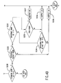
image receiving member 40. Furthermore, theprinthead 34 does not have to print with the high frequency that would be required for a grid timing of a 600 dpi pixel. - Figures 4A to 4D show a flowchart used in another embodiment where the edge enhancement step and the thinning step occur substantially simultaneously. Because the thinning and enhancement steps occur substantially simultaneously in this embodiment, the information used for determining the states of the output pixels is entirely contained in the low resolution input image (i.e., the 300 x 300 dpi pixel image). In this embodiment, each input pixel is replaced with two output pixels. A window of neighboring input pixels is used along with the input pixel to determine the states of the two output pixels corresponding to the input pixel. In this described embodiment, the window of neighboring pixels is three pixels wide (centered on the current pixel) and contains ten rows above the current row, twelve rows below the current row, and the current row. However, other embodiments of the window are also within the scope of this invention.
- Processing is based on a case analysis of the possible contents of the pixels in the window. In other words, the output pixels are determined based on the pattern of pixels within the window. There are eight possible cases (or patterns) for a three pixel wide window, corresponding to the eight possibilities of the current row. Some of these cases have subcases, depending on the possible contents of previous or subsequent rows as will be described below. For ease of illustration, the cases (or patterns) are labelled in binary as 000 through 111 where a 0 indicates no ink in the input pixel (OFF), and 1 indicates ink for the pixel (ON). For example, 001 indicates the current pixel is white, the neighbor to the left is white, and the neighbor to the right is black.
- One implementation of this embodiment will be described with respect to the flow chart of Figures 4A to 4D. It is understood that Figures 4A to 4D are merely illustrative and are not limiting. In
step 200, a window is formed around the current pixel to be examined. As explained above, the window preferably is three pixels wide (centered on the current pixel) and contains ten rows above the current row, twelve rows below the current row and the current row. Decision steps 202, 210, 220, 230, 240, 250 and 260 are used to determine the states (pattern) of the current row. Based on the pattern of the current row, the current input pixel will be output as two output pixels insteps - For example, in step 202 if the current row is 000 then the current pixel is in a region of white. In this case, the current pixel is output as two
pixels 00 in step 204. The window is then appropriately moved instep 280 to a next pixel. In step 210, if the current row is 001 then the window is tested in step 212 to determine whether an edge transition occurs within the window by looking at the rows above and below the current row. This step 212 will be described below in greater detail. If no edge transition occurs in step 212, the current pixel is output as twopixels 00 in step 218. Otherwise, in step 214 it is determined whether the differing rows (corresponding to the edge transition) are 010 or 011. If the differing rows are a 010 or a 011 pattern, the current pixel is output as twopixels 01 in step 216. Otherwise, twopixels 00 are output in step 218 for the pixels corresponding to the current pixel. A next current pixel is similarly examined instep 280. - When the current row is a 010 pattern in step 220, step 222 determines whether an edge transition occurs. If no edge transition occurs within the window in step 222 then two
pixels 10 are output for the current pixel in step 228. However, when an edge transition occurs as will be described below, the step 224 looks for a left edge transition (a 100 pattern) so that the current pixel is output as twopixels 00 in step 226. If there is a right edge transition the current pixel is output as twopixels 01 in step 227. While step 228 shows a 10 pixel pattern being output when no edge transition occurs, a 01 pixel pattern could also be output. Similarly, an alternating pattern of 01 and 10 could be used on successive scanlines. -
Decision step 230 determines when a 011 pattern occurs for the current row of the window. Step 232 tests for an edge transition. When an edge transition occurs, the differing rows are examined in step 233. If the differing rows are a 111 pattern, and the row is odd, a 00 is output in step 237. If it is an even row, two pixels having a 01 pattern are output in step 236. If the differing rows are a 101 pattern or a 001 pattern, two pixels having a 01 pattern are output for the pixels corresponding to the current input pixel. If there is no transition, or it fails both of the above tests, thedefault 10 pattern is produced at step 238. - When the current row is a 100 pattern in
step 240, then based on the steps 242 and 244, either a 10 pattern or a 00 pattern in step 248 is output for the two corresponding pixels. Ifdecision step 250 determines that the current row is a 101 pattern then the current pixel can be output as two pixels having a 10 pattern instep 255, a 01 pattern in step 257 and a 00 pattern in step 258. Similarly, when the current row is a 110 pattern in step 260, then steps 262, 264, 265 and 267 are used to output two pixels having a 10 pattern in step 266, a 01 pattern in step 268 or a 00 pattern instep 269. - Finally, if processing results in a negative response in step 260, then the current row is a 111 pattern corresponding to an all black region. In this case, the pattern output for the two pixels corresponding to the current input pixel will correspond to a checkerboard pattern unless there is a transition as found in step 272. If the row is a even row in step 273, then two pixels having a 01 pattern is output in step 272. If the row is a odd row, then two pixels having a 10 pattern is output for the current pixel. That is, when an all black region occurs, the rows will be altered to form a checkerboard pattern among the respective rows. If step 272 indicates a transition and it is an even row, a 00 patern for the two pixels is generated in step 276; otherwise, if it is an odd row, a 10 pattern is output in step 275.
- One embodiment to determine whether an edge transition occurs within the window will now be described. Accordingly, the following description can be used in
steps 212, 222, 232, 242, 252, 262 and 270 of Figure 4. For ease of illustration, the current scanline (or row) is numbered scanline i. Scanlines above scanline i are consecutively numbered i-1, i-2, i-3 etc. Scanlines below scanline i are consecutively numbered i + 1, i + 2, i + 3 etc. Testing for edge transitions is accomplished by examining the respective scanlines with respect to the following eight cases. - 1) if row i is identical to row i - 1, and different from row i + 1, row i is a potential toggle row.
- 2) if row i + 1 is identical to rows i through i - 4, and different from row i + 2, row i is a potential toggle row.
- 3) if row i + 2 is identical to rows i + 1 through i - 7, and different from row i + 3, row i is a potential toggle row.
- 4) if row i + 3 is identical to rows i + 2 through i - 10, and different from row i + 4, row i is a potential toggle row.
- 5) if row i - 1 is different from row i, and rows i through i + 3 are identical, row i is a potential toggle row.
- 6) if row i - 2 is different from row i - 1, and rows i - 1 through i + 6are identical, row i is a potential toggle row.
- 7) if row i - 3 is different from row i-2, and rows i-2 through i+9 are identical, row i is a potential toggle row.
- 8) if row i - 4 is different from row i - 3, and rows i - 3 through i + 12 are identical, row i is a potential toggle row.
- Accordingly, Figure 4 shows a method where the edge enhancement and the thinning step occur simultaneously. This can be done by matching patterns or other embodiments as is known in the art. Furthermore, it can be appreciated that the above embodiments can also increase the number of pixels, enhance the edges and thin the pixels all simultaneously. For example, a three pixel wide window may be provided to convert three pixels into four pixels based on the pattern of the three pixels. If an interior region (BBB) is encountered then the pixels may be appropriately thinned as a BWBW pattern or a WBWB pattern depending on whether the row is an odd pixel row or an even pixel row. If an edge region is encountered, then the pixels may be altered to enhance the edge and also perform thinning. By using a three pixel wide window, the steps of increasing the resolution, enhancing the edges and thinning the image may occur simultaneously as described with respect to Figure 4 in one embodiment. However, the above-described method is described in steps to be more illustrative.
Claims (10)
- A resolution enhancement method for printing a pixel image using an ink jet printer having a defined resolution along a raster scan axis, the method comprising the steps of:receiving the pixel image having the defined resolution along the raster scan axis;increasing a resolution of the pixel image along the raster scan axis;thinning the pixel image; andraster scanning the thinned pixel image with the ink jet printer to visibly reproduce the pixel image at the increased resolution.
- The method of claim 1, wherein the resolution increasing step and the thinning step occur substantially simultaneously.
- The method of claim 1, wherein the resolution increasing step comprises increasing a number of pixels in the pixel image.
- The method of claim 3, wherein the resolution increasing step further comprises adding or deleting pixels along an edge of the pixel image.
- The method of claim 1, wherein the thinning step maintains edges of the pixel image.
- The method of claim 1, wherein the thinning step comprises turning OFF interior pixels from the pixel image having the increased resolution.
- The method of claim 1, wherein the resolution increasing step increases a grid timing of the ink jet printer.
- A resolution enhancement method for printing a pixel image using an ink jet printer having a defined resolution along a raster scan axis, the pixel image comprising a plurality of pixel rows each extending along the raster scan axis and a plurality of pixel columns each extending along a direction perpendicular to the raster scan axis, the method comprising the steps of:receiving the pixel image having the defined resolution along the raster scan axis;producing an altered pixel image having a resolution along the raster scan axis greater than the defined resolution;turning OFF pixels in the altered pixel image; andprinting remaining pixels from the altered pixel image using the ink jet printer having the defined resolution to visibly reproduce the pixel image at the resolution along the raster scan axis greater than the defined resolution.
- A resolution enhancement method for printing a pixel image using an ink jet printer having a defined resolution along a raster scan axis, the method comprising the steps of:receiving the pixel image having the defined resolution, the pixel image comprising a plurality of ON pixels;increasing a number of ON pixels in the received pixel image to form an altered pixel image, each one of the increased number of ON pixels having a greater resolution along the raster scan axis than the defined resolution;thinning the altered pixel image; andfiring ink drops from the ink jet printer at areas corresponding to remaining ON pixels of the thinned altered pixel image to visibly reproduce the pixel image at the greater resolution along the raster scan axis.
- A resolution enhancement method for printing a pixel image using an ink jet printer having a defined resolution along a raster scan axis, the method comprising the steps of:receiving the pixel image having the defined resolution, the pixel image comprising a plurality of pixels;producing an altered pixel image from the received pixel image, the altered pixel image having an increased resolution along the raster scan axis, selected ones of pixels within the altered pixel image being turned OFF; andraster scanning the altered pixel image with the ink jet printer to visibly reproduce the pixel image at the increased resolution.
Applications Claiming Priority (2)
| Application Number | Priority Date | Filing Date | Title |
|---|---|---|---|
| US368139 | 1995-01-03 | ||
| US08/368,139 US5742300A (en) | 1995-01-03 | 1995-01-03 | Resolution enhancement and thinning method for printing pixel images |
Publications (2)
| Publication Number | Publication Date |
|---|---|
| EP0720919A1 true EP0720919A1 (en) | 1996-07-10 |
| EP0720919B1 EP0720919B1 (en) | 1998-07-15 |
Family
ID=23450009
Family Applications (1)
| Application Number | Title | Priority Date | Filing Date |
|---|---|---|---|
| EP96300048A Expired - Lifetime EP0720919B1 (en) | 1995-01-03 | 1996-01-03 | Resolution enhancement and thinning method for printing pixel images |
Country Status (4)
| Country | Link |
|---|---|
| US (1) | US5742300A (en) |
| EP (1) | EP0720919B1 (en) |
| JP (1) | JPH08258255A (en) |
| DE (1) | DE69600415T2 (en) |
Cited By (2)
| Publication number | Priority date | Publication date | Assignee | Title |
|---|---|---|---|---|
| US6406111B1 (en) * | 1998-09-03 | 2002-06-18 | Xerox Corporation | Method of increasing the resolution of an ink jet printer |
| EP1316429A1 (en) * | 1998-09-03 | 2003-06-04 | Videojet Technologies Inc. | An Ink Jet Printing System |
Families Citing this family (23)
| Publication number | Priority date | Publication date | Assignee | Title |
|---|---|---|---|---|
| JPH09272203A (en) * | 1996-02-09 | 1997-10-21 | Canon Inc | Ink jet recording device and method |
| US6049393A (en) * | 1997-11-19 | 2000-04-11 | Tektronix, Inc. | Method for enhancing resolution in a printed image |
| JP3775935B2 (en) * | 1999-01-19 | 2006-05-17 | 武藤工業株式会社 | Method for deleting dots in an ink jet printer |
| US6604806B1 (en) | 1999-10-20 | 2003-08-12 | Canon Kabushiki Kaisha | High resolution printing |
| US7185963B1 (en) * | 2000-02-01 | 2007-03-06 | Hewlett-Packard Development Company, L.P. | Enhancement technique for asymmetrical print resolution |
| US6318832B1 (en) | 2000-03-24 | 2001-11-20 | Lexmark International, Inc. | High resolution printing |
| US6609776B2 (en) * | 2001-05-24 | 2003-08-26 | Hewlett-Packard Company | Inkjet printing system with ink-efficient font |
| IL151354A (en) * | 2002-08-20 | 2005-11-20 | Zach Moshe | Multi-printhead digital printer |
| US20040190786A1 (en) * | 2003-03-24 | 2004-09-30 | Khageshwar Thakur | Method of image enhancement for an imaging apparatus |
| JP2005201972A (en) * | 2004-01-13 | 2005-07-28 | Fuji Photo Film Co Ltd | Image recording method and device |
| US20060103857A1 (en) * | 2004-11-17 | 2006-05-18 | Lexmark International, Inc. | Method of reducing a consumption of imaging substance when forming an image |
| US9299196B2 (en) * | 2004-12-22 | 2016-03-29 | Pitney Bowes Inc. | Method and system for high speed printing using drop-on demand technology that compensates for droplet satellites |
| TWI259145B (en) * | 2004-12-29 | 2006-08-01 | Ind Tech Res Inst | Method for converting printing data and device using the same |
| CN100374301C (en) * | 2004-12-31 | 2008-03-12 | 财团法人工业技术研究院 | Printing data conversion method and apparatus thereof |
| DE102006035254A1 (en) * | 2006-07-26 | 2008-01-31 | Francotyp-Postalia Gmbh | Printout producing method for use in franking machine, involves determining whether pixels are produced using plausibilities and random generator, and producing pixels during subsequent printing step depending on result of determination |
| US8078007B2 (en) * | 2008-01-08 | 2011-12-13 | Seiko Epson Corporation | Enlarging a digital image |
| US8201909B2 (en) * | 2008-12-03 | 2012-06-19 | Videojet Technologies Inc. | Inkjet printing system and method |
| JP2012056141A (en) * | 2010-09-07 | 2012-03-22 | Seiko Epson Corp | Print apparatus and print method |
| JP5754176B2 (en) * | 2011-03-03 | 2015-07-29 | セイコーエプソン株式会社 | Image forming apparatus and image forming method |
| JP5779912B2 (en) * | 2011-03-04 | 2015-09-16 | セイコーエプソン株式会社 | Image forming apparatus and image forming method |
| JP5887699B2 (en) * | 2011-03-04 | 2016-03-16 | セイコーエプソン株式会社 | Image forming apparatus and image forming method |
| JP5927984B2 (en) | 2012-02-28 | 2016-06-01 | ブラザー工業株式会社 | Image processing apparatus and image processing program |
| US10787000B2 (en) | 2017-12-28 | 2020-09-29 | Assa Abloy Ab | Thermal printhead having asymmetric recording elements |
Citations (5)
| Publication number | Priority date | Publication date | Assignee | Title |
|---|---|---|---|---|
| US4437122A (en) | 1981-09-12 | 1984-03-13 | Xerox Corporation | Low resolution raster images |
| US4774530A (en) | 1987-11-02 | 1988-09-27 | Xerox Corporation | Ink jet printhead |
| US5029108A (en) | 1990-09-24 | 1991-07-02 | Destiny Technology Corporation | Edge enhancement method and apparatus for dot matrix devices |
| WO1992004191A1 (en) * | 1990-09-10 | 1992-03-19 | Mannesmann Ag | Process for reducing the quantity of ink applied to recording substrates by ink writing devices |
| EP0513989A2 (en) * | 1991-04-17 | 1992-11-19 | Hewlett-Packard Company | Raster imaging device speed-resolution product multiplying method and resulting pixel image data structure |
Family Cites Families (6)
| Publication number | Priority date | Publication date | Assignee | Title |
|---|---|---|---|---|
| JPS60116464A (en) * | 1983-11-30 | 1985-06-22 | Toshiba Corp | Printer |
| DE3925913A1 (en) * | 1989-08-04 | 1991-02-07 | Siemens Ag | METHOD FOR DRIVING PRINTING ELEMENTS |
| US4967203A (en) * | 1989-09-29 | 1990-10-30 | Hewlett-Packard Company | Interlace printing process |
| US5353387A (en) * | 1990-09-10 | 1994-10-04 | Mannesmann Aktiengesellschaft | Process for reducing the quantity of ink applied to recording substrates by ink printing devices to prevent image degradation |
| JP2986124B2 (en) * | 1991-06-14 | 1999-12-06 | キヤノン株式会社 | Ink jet recording device |
| US5469198A (en) * | 1992-08-03 | 1995-11-21 | Hewlett-Packard Company | Multiple pass printing for achieving increased print resolution |
-
1995
- 1995-01-03 US US08/368,139 patent/US5742300A/en not_active Expired - Lifetime
- 1995-12-26 JP JP7338885A patent/JPH08258255A/en active Pending
-
1996
- 1996-01-03 DE DE69600415T patent/DE69600415T2/en not_active Expired - Lifetime
- 1996-01-03 EP EP96300048A patent/EP0720919B1/en not_active Expired - Lifetime
Patent Citations (7)
| Publication number | Priority date | Publication date | Assignee | Title |
|---|---|---|---|---|
| US4437122A (en) | 1981-09-12 | 1984-03-13 | Xerox Corporation | Low resolution raster images |
| US4437122B1 (en) | 1981-09-12 | 1993-03-30 | Xerox Corp | |
| US4774530A (en) | 1987-11-02 | 1988-09-27 | Xerox Corporation | Ink jet printhead |
| WO1992004191A1 (en) * | 1990-09-10 | 1992-03-19 | Mannesmann Ag | Process for reducing the quantity of ink applied to recording substrates by ink writing devices |
| US5029108A (en) | 1990-09-24 | 1991-07-02 | Destiny Technology Corporation | Edge enhancement method and apparatus for dot matrix devices |
| EP0513989A2 (en) * | 1991-04-17 | 1992-11-19 | Hewlett-Packard Company | Raster imaging device speed-resolution product multiplying method and resulting pixel image data structure |
| US5270728A (en) | 1991-04-17 | 1993-12-14 | Hewlett-Packard Company | Raster imaging device speed-resolution product multiplying method and resulting pixel image data structure |
Cited By (2)
| Publication number | Priority date | Publication date | Assignee | Title |
|---|---|---|---|---|
| US6406111B1 (en) * | 1998-09-03 | 2002-06-18 | Xerox Corporation | Method of increasing the resolution of an ink jet printer |
| EP1316429A1 (en) * | 1998-09-03 | 2003-06-04 | Videojet Technologies Inc. | An Ink Jet Printing System |
Also Published As
| Publication number | Publication date |
|---|---|
| DE69600415D1 (en) | 1998-08-20 |
| JPH08258255A (en) | 1996-10-08 |
| DE69600415T2 (en) | 1999-02-04 |
| EP0720919B1 (en) | 1998-07-15 |
| US5742300A (en) | 1998-04-21 |
Similar Documents
| Publication | Publication Date | Title |
|---|---|---|
| EP0720919B1 (en) | Resolution enhancement and thinning method for printing pixel images | |
| EP0817113B1 (en) | Ink jet recording method | |
| US5270728A (en) | Raster imaging device speed-resolution product multiplying method and resulting pixel image data structure | |
| US6533382B1 (en) | Ink-jet recording method, ink-jet recording apparatus, computer-readable medium, and program | |
| EP0730246A1 (en) | Method of transitioning between ink jet printing modes | |
| EP0816103A2 (en) | Method for liquid ink printing | |
| JPH0732650A (en) | Biaxial dot reduction for obtaining 600 dpi edge sharpness using 300 dpi printing cartridge | |
| EP2233302A2 (en) | Inkjet printer and printing method | |
| US6217150B1 (en) | Method of printing with an ink jet printer using multiple carriage speeds | |
| JPH09164706A (en) | Ink jet head | |
| JP2003127438A (en) | Printing controller, method of controlling printing, printing control program, medium containing printing control program, printer, and method of printing | |
| US6406111B1 (en) | Method of increasing the resolution of an ink jet printer | |
| EP0720911A2 (en) | Neighbor insensitive pixel deletion method for printing high resolution image | |
| US6886912B2 (en) | Method and apparatus for processing images having color combinations | |
| US8040556B2 (en) | Image data generating method, printing method, image data generating apparatus, and printer | |
| EP0720918B1 (en) | Edge insensitive pixel deletion method for printing high resolution image | |
| US5959646A (en) | Method of printing with an ink jet printer using independent shingling on a raster by raster basis | |
| US9189716B2 (en) | Generating a threshold matrix to be compared with an original image for performing halftoning of the original image | |
| EP0795838B1 (en) | Apparatus and method of interlaced printing | |
| US20030137556A1 (en) | Draft printing with multiple same-hue ink nozzles | |
| JPH06127032A (en) | Recording apparatus | |
| EP0854047A2 (en) | Method of and machine for liquid ink printing | |
| US20010038457A1 (en) | Method and device for processing a document available in the form of a set of digital data | |
| JP2003089199A (en) | Ink jet recorder | |
| EP1076881B1 (en) | Method of interlaced printing using an inkjet printer |
Legal Events
| Date | Code | Title | Description |
|---|---|---|---|
| PUAI | Public reference made under article 153(3) epc to a published international application that has entered the european phase |
Free format text: ORIGINAL CODE: 0009012 |
|
| AK | Designated contracting states |
Kind code of ref document: A1 Designated state(s): DE FR GB |
|
| 17P | Request for examination filed |
Effective date: 19970110 |
|
| GRAG | Despatch of communication of intention to grant |
Free format text: ORIGINAL CODE: EPIDOS AGRA |
|
| 17Q | First examination report despatched |
Effective date: 19971216 |
|
| GRAG | Despatch of communication of intention to grant |
Free format text: ORIGINAL CODE: EPIDOS AGRA |
|
| GRAH | Despatch of communication of intention to grant a patent |
Free format text: ORIGINAL CODE: EPIDOS IGRA |
|
| GRAH | Despatch of communication of intention to grant a patent |
Free format text: ORIGINAL CODE: EPIDOS IGRA |
|
| GRAA | (expected) grant |
Free format text: ORIGINAL CODE: 0009210 |
|
| AK | Designated contracting states |
Kind code of ref document: B1 Designated state(s): DE FR GB |
|
| REF | Corresponds to: |
Ref document number: 69600415 Country of ref document: DE Date of ref document: 19980820 |
|
| ET | Fr: translation filed | ||
| PLBE | No opposition filed within time limit |
Free format text: ORIGINAL CODE: 0009261 |
|
| STAA | Information on the status of an ep patent application or granted ep patent |
Free format text: STATUS: NO OPPOSITION FILED WITHIN TIME LIMIT |
|
| 26N | No opposition filed | ||
| REG | Reference to a national code |
Ref country code: GB Ref legal event code: IF02 |
|
| PGFP | Annual fee paid to national office [announced via postgrant information from national office to epo] |
Ref country code: DE Payment date: 20101230 Year of fee payment: 16 |
|
| PG25 | Lapsed in a contracting state [announced via postgrant information from national office to epo] |
Ref country code: DE Free format text: LAPSE BECAUSE OF NON-PAYMENT OF DUE FEES Effective date: 20120801 |
|
| REG | Reference to a national code |
Ref country code: DE Ref legal event code: R119 Ref document number: 69600415 Country of ref document: DE Effective date: 20120801 |
|
| PGFP | Annual fee paid to national office [announced via postgrant information from national office to epo] |
Ref country code: GB Payment date: 20131223 Year of fee payment: 19 |
|
| PGFP | Annual fee paid to national office [announced via postgrant information from national office to epo] |
Ref country code: FR Payment date: 20140120 Year of fee payment: 19 |
|
| GBPC | Gb: european patent ceased through non-payment of renewal fee |
Effective date: 20150103 |
|
| PG25 | Lapsed in a contracting state [announced via postgrant information from national office to epo] |
Ref country code: GB Free format text: LAPSE BECAUSE OF NON-PAYMENT OF DUE FEES Effective date: 20150103 |
|
| REG | Reference to a national code |
Ref country code: FR Ref legal event code: ST Effective date: 20150930 |
|
| PG25 | Lapsed in a contracting state [announced via postgrant information from national office to epo] |
Ref country code: FR Free format text: LAPSE BECAUSE OF NON-PAYMENT OF DUE FEES Effective date: 20150202 |