EP0721178A2 - Multi-channel communication system - Google Patents
Multi-channel communication system Download PDFInfo
- Publication number
- EP0721178A2 EP0721178A2 EP96300078A EP96300078A EP0721178A2 EP 0721178 A2 EP0721178 A2 EP 0721178A2 EP 96300078 A EP96300078 A EP 96300078A EP 96300078 A EP96300078 A EP 96300078A EP 0721178 A2 EP0721178 A2 EP 0721178A2
- Authority
- EP
- European Patent Office
- Prior art keywords
- model
- noise
- error
- input
- summer
- Prior art date
- Legal status (The legal status is an assumption and is not a legal conclusion. Google has not performed a legal analysis and makes no representation as to the accuracy of the status listed.)
- Granted
Links
Images
Classifications
-
- G—PHYSICS
- G10—MUSICAL INSTRUMENTS; ACOUSTICS
- G10K—SOUND-PRODUCING DEVICES; METHODS OR DEVICES FOR PROTECTING AGAINST, OR FOR DAMPING, NOISE OR OTHER ACOUSTIC WAVES IN GENERAL; ACOUSTICS NOT OTHERWISE PROVIDED FOR
- G10K11/00—Methods or devices for transmitting, conducting or directing sound in general; Methods or devices for protecting against, or for damping, noise or other acoustic waves in general
- G10K11/16—Methods or devices for protecting against, or for damping, noise or other acoustic waves in general
- G10K11/175—Methods or devices for protecting against, or for damping, noise or other acoustic waves in general using interference effects; Masking sound
- G10K11/178—Methods or devices for protecting against, or for damping, noise or other acoustic waves in general using interference effects; Masking sound by electro-acoustically regenerating the original acoustic waves in anti-phase
- G10K11/1787—General system configurations
- G10K11/17885—General system configurations additionally using a desired external signal, e.g. pass-through audio such as music or speech
-
- G—PHYSICS
- G10—MUSICAL INSTRUMENTS; ACOUSTICS
- G10K—SOUND-PRODUCING DEVICES; METHODS OR DEVICES FOR PROTECTING AGAINST, OR FOR DAMPING, NOISE OR OTHER ACOUSTIC WAVES IN GENERAL; ACOUSTICS NOT OTHERWISE PROVIDED FOR
- G10K11/00—Methods or devices for transmitting, conducting or directing sound in general; Methods or devices for protecting against, or for damping, noise or other acoustic waves in general
- G10K11/16—Methods or devices for protecting against, or for damping, noise or other acoustic waves in general
- G10K11/175—Methods or devices for protecting against, or for damping, noise or other acoustic waves in general using interference effects; Masking sound
- G10K11/178—Methods or devices for protecting against, or for damping, noise or other acoustic waves in general using interference effects; Masking sound by electro-acoustically regenerating the original acoustic waves in anti-phase
- G10K11/1781—Methods or devices for protecting against, or for damping, noise or other acoustic waves in general using interference effects; Masking sound by electro-acoustically regenerating the original acoustic waves in anti-phase characterised by the analysis of input or output signals, e.g. frequency range, modes, transfer functions
- G10K11/17813—Methods or devices for protecting against, or for damping, noise or other acoustic waves in general using interference effects; Masking sound by electro-acoustically regenerating the original acoustic waves in anti-phase characterised by the analysis of input or output signals, e.g. frequency range, modes, transfer functions characterised by the analysis of the acoustic paths, e.g. estimating, calibrating or testing of transfer functions or cross-terms
- G10K11/17817—Methods or devices for protecting against, or for damping, noise or other acoustic waves in general using interference effects; Masking sound by electro-acoustically regenerating the original acoustic waves in anti-phase characterised by the analysis of input or output signals, e.g. frequency range, modes, transfer functions characterised by the analysis of the acoustic paths, e.g. estimating, calibrating or testing of transfer functions or cross-terms between the output signals and the error signals, i.e. secondary path
-
- G—PHYSICS
- G10—MUSICAL INSTRUMENTS; ACOUSTICS
- G10K—SOUND-PRODUCING DEVICES; METHODS OR DEVICES FOR PROTECTING AGAINST, OR FOR DAMPING, NOISE OR OTHER ACOUSTIC WAVES IN GENERAL; ACOUSTICS NOT OTHERWISE PROVIDED FOR
- G10K11/00—Methods or devices for transmitting, conducting or directing sound in general; Methods or devices for protecting against, or for damping, noise or other acoustic waves in general
- G10K11/16—Methods or devices for protecting against, or for damping, noise or other acoustic waves in general
- G10K11/175—Methods or devices for protecting against, or for damping, noise or other acoustic waves in general using interference effects; Masking sound
- G10K11/178—Methods or devices for protecting against, or for damping, noise or other acoustic waves in general using interference effects; Masking sound by electro-acoustically regenerating the original acoustic waves in anti-phase
- G10K11/1785—Methods, e.g. algorithms; Devices
- G10K11/17853—Methods, e.g. algorithms; Devices of the filter
- G10K11/17854—Methods, e.g. algorithms; Devices of the filter the filter being an adaptive filter
-
- G—PHYSICS
- G10—MUSICAL INSTRUMENTS; ACOUSTICS
- G10K—SOUND-PRODUCING DEVICES; METHODS OR DEVICES FOR PROTECTING AGAINST, OR FOR DAMPING, NOISE OR OTHER ACOUSTIC WAVES IN GENERAL; ACOUSTICS NOT OTHERWISE PROVIDED FOR
- G10K11/00—Methods or devices for transmitting, conducting or directing sound in general; Methods or devices for protecting against, or for damping, noise or other acoustic waves in general
- G10K11/16—Methods or devices for protecting against, or for damping, noise or other acoustic waves in general
- G10K11/175—Methods or devices for protecting against, or for damping, noise or other acoustic waves in general using interference effects; Masking sound
- G10K11/178—Methods or devices for protecting against, or for damping, noise or other acoustic waves in general using interference effects; Masking sound by electro-acoustically regenerating the original acoustic waves in anti-phase
- G10K11/1787—General system configurations
- G10K11/17879—General system configurations using both a reference signal and an error signal
- G10K11/17881—General system configurations using both a reference signal and an error signal the reference signal being an acoustic signal, e.g. recorded with a microphone
-
- G—PHYSICS
- G10—MUSICAL INSTRUMENTS; ACOUSTICS
- G10K—SOUND-PRODUCING DEVICES; METHODS OR DEVICES FOR PROTECTING AGAINST, OR FOR DAMPING, NOISE OR OTHER ACOUSTIC WAVES IN GENERAL; ACOUSTICS NOT OTHERWISE PROVIDED FOR
- G10K11/00—Methods or devices for transmitting, conducting or directing sound in general; Methods or devices for protecting against, or for damping, noise or other acoustic waves in general
- G10K11/16—Methods or devices for protecting against, or for damping, noise or other acoustic waves in general
- G10K11/175—Methods or devices for protecting against, or for damping, noise or other acoustic waves in general using interference effects; Masking sound
- G10K11/178—Methods or devices for protecting against, or for damping, noise or other acoustic waves in general using interference effects; Masking sound by electro-acoustically regenerating the original acoustic waves in anti-phase
- G10K11/1787—General system configurations
- G10K11/17879—General system configurations using both a reference signal and an error signal
- G10K11/17883—General system configurations using both a reference signal and an error signal the reference signal being derived from a machine operating condition, e.g. engine RPM or vehicle speed
-
- G—PHYSICS
- G10—MUSICAL INSTRUMENTS; ACOUSTICS
- G10K—SOUND-PRODUCING DEVICES; METHODS OR DEVICES FOR PROTECTING AGAINST, OR FOR DAMPING, NOISE OR OTHER ACOUSTIC WAVES IN GENERAL; ACOUSTICS NOT OTHERWISE PROVIDED FOR
- G10K11/00—Methods or devices for transmitting, conducting or directing sound in general; Methods or devices for protecting against, or for damping, noise or other acoustic waves in general
- G10K11/16—Methods or devices for protecting against, or for damping, noise or other acoustic waves in general
- G10K11/175—Methods or devices for protecting against, or for damping, noise or other acoustic waves in general using interference effects; Masking sound
- G10K11/178—Methods or devices for protecting against, or for damping, noise or other acoustic waves in general using interference effects; Masking sound by electro-acoustically regenerating the original acoustic waves in anti-phase
- G10K11/1785—Methods, e.g. algorithms; Devices
- G10K11/17857—Geometric disposition, e.g. placement of microphones
-
- G—PHYSICS
- G10—MUSICAL INSTRUMENTS; ACOUSTICS
- G10K—SOUND-PRODUCING DEVICES; METHODS OR DEVICES FOR PROTECTING AGAINST, OR FOR DAMPING, NOISE OR OTHER ACOUSTIC WAVES IN GENERAL; ACOUSTICS NOT OTHERWISE PROVIDED FOR
- G10K2210/00—Details of active noise control [ANC] covered by G10K11/178 but not provided for in any of its subgroups
- G10K2210/10—Applications
- G10K2210/108—Communication systems, e.g. where useful sound is kept and noise is cancelled
-
- G—PHYSICS
- G10—MUSICAL INSTRUMENTS; ACOUSTICS
- G10K—SOUND-PRODUCING DEVICES; METHODS OR DEVICES FOR PROTECTING AGAINST, OR FOR DAMPING, NOISE OR OTHER ACOUSTIC WAVES IN GENERAL; ACOUSTICS NOT OTHERWISE PROVIDED FOR
- G10K2210/00—Details of active noise control [ANC] covered by G10K11/178 but not provided for in any of its subgroups
- G10K2210/10—Applications
- G10K2210/128—Vehicles
-
- G—PHYSICS
- G10—MUSICAL INSTRUMENTS; ACOUSTICS
- G10K—SOUND-PRODUCING DEVICES; METHODS OR DEVICES FOR PROTECTING AGAINST, OR FOR DAMPING, NOISE OR OTHER ACOUSTIC WAVES IN GENERAL; ACOUSTICS NOT OTHERWISE PROVIDED FOR
- G10K2210/00—Details of active noise control [ANC] covered by G10K11/178 but not provided for in any of its subgroups
- G10K2210/30—Means
- G10K2210/301—Computational
- G10K2210/3012—Algorithms
-
- G—PHYSICS
- G10—MUSICAL INSTRUMENTS; ACOUSTICS
- G10K—SOUND-PRODUCING DEVICES; METHODS OR DEVICES FOR PROTECTING AGAINST, OR FOR DAMPING, NOISE OR OTHER ACOUSTIC WAVES IN GENERAL; ACOUSTICS NOT OTHERWISE PROVIDED FOR
- G10K2210/00—Details of active noise control [ANC] covered by G10K11/178 but not provided for in any of its subgroups
- G10K2210/30—Means
- G10K2210/301—Computational
- G10K2210/3019—Cross-terms between multiple in's and out's
-
- G—PHYSICS
- G10—MUSICAL INSTRUMENTS; ACOUSTICS
- G10K—SOUND-PRODUCING DEVICES; METHODS OR DEVICES FOR PROTECTING AGAINST, OR FOR DAMPING, NOISE OR OTHER ACOUSTIC WAVES IN GENERAL; ACOUSTICS NOT OTHERWISE PROVIDED FOR
- G10K2210/00—Details of active noise control [ANC] covered by G10K11/178 but not provided for in any of its subgroups
- G10K2210/30—Means
- G10K2210/301—Computational
- G10K2210/3027—Feedforward
-
- G—PHYSICS
- G10—MUSICAL INSTRUMENTS; ACOUSTICS
- G10K—SOUND-PRODUCING DEVICES; METHODS OR DEVICES FOR PROTECTING AGAINST, OR FOR DAMPING, NOISE OR OTHER ACOUSTIC WAVES IN GENERAL; ACOUSTICS NOT OTHERWISE PROVIDED FOR
- G10K2210/00—Details of active noise control [ANC] covered by G10K11/178 but not provided for in any of its subgroups
- G10K2210/30—Means
- G10K2210/301—Computational
- G10K2210/3042—Parallel processing
-
- G—PHYSICS
- G10—MUSICAL INSTRUMENTS; ACOUSTICS
- G10K—SOUND-PRODUCING DEVICES; METHODS OR DEVICES FOR PROTECTING AGAINST, OR FOR DAMPING, NOISE OR OTHER ACOUSTIC WAVES IN GENERAL; ACOUSTICS NOT OTHERWISE PROVIDED FOR
- G10K2210/00—Details of active noise control [ANC] covered by G10K11/178 but not provided for in any of its subgroups
- G10K2210/50—Miscellaneous
- G10K2210/505—Echo cancellation, e.g. multipath-, ghost- or reverberation-cancellation
Definitions
- the invention relates to multi-channel communication systems, including active acoustic attenuation systems, and vehicle applications.
- the invention arose during continuing development efforts relating to the subject matter of U.S. Patents 4,677,676, 5,033,082, 5,216,721 and 5,216,722, all incorporated herein by reference.
- the invention involves an intercom communication system in a multi-channel application having one or more zones subject to noise from one or more noise sources, and one or more speaking locations in each zone.
- One exemplary application of the invention is in an automobile where the front seat is a first zone and the rear seat is a second zone, and the left front passenger is in a first speaking location, the right front passenger is in a second speaking location, the left rear passenger is in a third speaking location, and the right rear passenger is in a fourth speaking location.
- Engine noise, road noise, etc. is canceled at each location, including cross-coupled noise between channels, but not speech from another location.
- the invention has numerous other applications where communication is desired in multi-channel noisy environments.
- Fig. 1 shows an active acoustic attenuation system in accordance with the invention.
- Fig. 2 further illustrates a portion of the system of Fig. 1.
- Fig. 3 shows a further active acoustic attenuation system.
- Fig. 4 is an isometric view, partially cut away, illustrating a further embodiment of the invention.
- Fig. 5 is a sectional view taken along line 5-5 of Fig. 4.
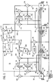
- Fig. 1 shows an active acoustic attenuation system 10 including plural zones such as 12 and 14 subject to noise from one or more noise sources.
- Each zone includes one or more speaking locations, for example 18 and 20 in zone 12, and 22 and 24 in zone 14, such that a person at a speaking location is subject to noise from one or more noise sources.
- Speakers 26 and 28 introduce sound into zone 12 at respective speaking locations 18 and 20.
- Speakers 30 and 32 introduce sound into zone 14 at respective speaking locations 22 and 24.
- Error microphones 34 and 36 sense noise and speech at respective speaking locations 18 and 20.
- Error microphones 38 and 40 sense noise and speech at respective speaking locations 22 and 24.
- a plurality of adaptive filter models M1, M2, M3, M4 each cancel noise from a respective noise source at a respective speaking location as sensed by a respective error microphone.
- Model M1 has a model input 42 from a reference signal correlated to the noise from the respective noise source.
- Model M1 has a plurality of error inputs 44, 46, 48, 50 from respective error microphones 34, 36, 38, 40.
- Model M1 has an output 52 outputting a correction signal to introduce canceling sound at respective speaking location 18 to cancel noise from respective noise source 16, such that the output of error microphone 34 carries a speech signal from a person at speaking location 18 but not a noise signal from noise source 16.
- Noise from source 16 is sensed at input transducer 54 provided by an input microphone which outputs a noise signal correlated to the noise.
- the input transducer may be provided by a tachometer or the like, or may be eliminated for example as in incorporated U.S. Patent 5,216,722.
- an input microphone is preferred for transducer 54 to sense engine noise, which is periodic but which period may change at changing engine speeds, and also to sense random noise such as road noise etc.
- Model M2 has a model input 56, error inputs 58, 60, 62, 64, and a model output 66.
- Model M3 has a model input 68, error inputs 70, 72, 74, 76, and a model output 78.
- Model M4 has a model input 80, error inputs 82, 84, 86, 88, and a model output 90.
- Models M2, M3 and M4 may receive their model input signals from the same transducer 54 as model M1 or from other transducers or may sense noise from other noise sources, for example as in incorporated U.S. Patent 5,033,082.
- each of the models receives its model input signal from the same reference signal correlated to engine and road noise, and have model output signals 52, 66, 78, 90, respectively to right front speaker 26, left front speaker 28, right rear speaker 30, left rear speaker 32 of an automobile.
- the output of error microphone 34 carrying the speech of a person at speaking location 18 is supplied to speakers 30 and 32 at speaking locations 22 and 24, such that a person at location 22 can hear the speech of the person at location 18, and a person at location 24 can hear the speech of the person at location 18.
- the output of error microphone 36 carrying the speech of a person at location 20 is supplied to speakers 30 and 32 at locations 22 and 24, such that a person at location 22 can hear the speech of a person at location 20, and a person at location 24 can hear the speech of a person at location 20.
- the output of error microphone 38 carrying the speech of a person at location 22 is supplied to speaker 26 at location 18 and to speaker 28 at location 20, such that a person at location 18 can hear the speech of a person at location 22, and a person at location 20 can hear the speech of a person at location 22.
- the output of error microphone 40 carrying the speech of a person at location 24 is supplied to speaker 26 at location 18 and to speaker 28 at location 20, such that a person at location 18 can hear the speech of a person at location 24, and a person at location 20 can hear the speech of a person at location 24.
- Model M1 has error inputs 44, 46, 48, 50 from error microphones 34, 36, 38, 40, respectively.
- Model M1 has a model output 52 supplied to speaker 26.
- Model M2 has error inputs 58, 60, 62, 64 from error microphones 34, 36, 38, 40, respectively.
- Model M2 has a model output 66 supplied to speaker 28.
- Model M3 has error inputs 70, 72, 74, 76 from error microphones 34, 36, 38, 40, respectively.
- Model M3 has a model output 78 supplied to speaker 30.
- Model M4 has error inputs 82, 84, 86, 88 from error microphones 34, 36, 38, 40, respectively.
- Model M4 has a model output 90 supplied to speaker 32.
- zones 12 and 14 are subject to noise from a common noise source 16
- models M1, M2, M3, M4 have model inputs 42, 56, 68, 80, respectively, receiving a common reference signal from input microphone 54 correlated to noise from common noise source 16.
- Each of models M1, M2, M3, M4 is preferably an IIR (infinite impulse response) filter for example as disclosed in incorporated U.S. Patent 4,677,676, or alternatively an FIR (finite impulse response) filter, though other types of adaptive filter models may be used.
- Adaptive filter model M5 has a model input 92 receiving through summer 94 a noise signal from input microphone 54 correlated with noise from noise source 16.
- Model M5 has a model output 96 summed at summer 98 with the output of summer 100 which sums the outputs of error microphones 34 and 36.
- Model M5 has an error input 102 from the output of summer 98.
- Models M1 and M2 acoustically cancel noise in the respective outputs of error microphones 34 and 36, and model M5 electrically cancels noise in the outputs of error microphones 34 and 36.
- Summer 94 also has an input from audio source 104, which may for example be the audio system or the like of the automobile, to thus cancel such audio signal component in the signal supplied from summer 98 to speakers 30 and 32, such that a person at such locations hears only speech from locations 18 and 20 and not road noise nor noise from the automobile radio or audio system.
- Model M6 has a model input 106 from summer 94.
- Model M6 has a model output 108 summed at summer 110 with the output of summer 111 which sums the outputs of error microphones 38 and 40.
- Model M6 has an error input 112 from the output of summer 110.
- Model M6 electrically cancels noise from noise source 16 and audio noise or sound from source 104 in the signal transmitted to speakers 26 and 28.
- Model M7 has a model input 114 from the signal from error microphones 38 and 40, a model output 116 summed at summer 118 with the output of summer 98, and an error input 120 from the output of summer 118.
- Model M7 cancels the speech of a person at locations 22 or 24 in the signal sent to speakers 30 and 32 at such locations 22 and 24, to thus eliminate echo.
- Model M8 has a model input 122 from the signal from error microphones 34 and 36, a model output 124 supplied to summer 126, and an error input 128 from the output of summer 126.
- Model M8 cancels the speech of persons at locations 18 and 20 from the signal sent to speakers 26 and 28 at such locations 18 and 20, to eliminate echo.
- Each of models M5, M6, M7, M8 is preferably an FIR filter, though other types of adaptive filters may be used.
- Summer 130 has an input from model M1 and an input from summer 126, and has an output supplied to speaker 26.
- Summer 132 has an input from model M2 and an input from summer 126, and has an output supplied to speaker 28.
- Summer 134 has an input from model M3 and an input from summer 118, and has an output supplied to speaker 30.
- Summer 136 has an input from model M4 and an input from summer 118, and has an output supplied to speaker 32.
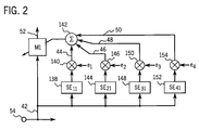
- each channel model M1, M2, M3, M4 has an error input from each of the error microphones 34, 36, 38, 40.
- the system includes a plurality of error paths, including a first set of error paths including an error path SE 11 to the first error microphone 34 from the first speaker 26, an error path SE 21 to the second error microphone 36 from the first speaker 26, an error path SE 31 to the third error microphone 38 from the first speaker 26, and an error path SE 41 to the fourth error microphone 40 from the first speaker 26, i.e. between speaker 26 and each of error microphones 34, 36, 38, 40.
- error paths from speaker 28 to each of error microphones 34, 36, 38, 40, and from speaker 30 to each of error microphones 34, 36, 38, 40, and from speaker 32 to each of error microphones 34, 36, 38, 40.
- these error paths are modeled, and the transfer functions thereof are provided in the channel models.
- M1 model input 42 is supplied through error path transfer function model SE 11 at 138, Fig. 2, and multiplied at multiplier 140 with the error signal e 1 from error microphone 34 to provide a weight update signal to summer 142.
- Model input 42 is supplied through the SE 21 error path transfer function model at 144 and multiplied at multiplier 146 with the error signal e 2 from error microphone 36 to provide a weight update signal to summer 142.
- Model input 42 is supplied through the error path SE 31 transfer function model at 148 and multiplied at multiplier 150 with error signal e 3 from error microphone 38 to provide a weight update signal to summer 142.
- Model input 42 is supplied through the error path SE 41 transfer function model at 152 and multiplied at multiplier 154 with error signal e 4 from error microphone 40 to provide a weight update signal to summer 142.
- the output of summer 142 provides the weight update signal for model M1.
- the multiple error signal processing for models M2, M3, M4 is comparable, and for which further reference may be had to incorporated U.S. Patents 5,216,721 and 5,216,722.
- models M1, M2, M3, M4 acoustically cancel or control noise, and models M5, M6, M7, M8 electrically cancel or control noise.
- Models M1, M2, M3, M4 preferably include SE modeling, as noted above, and as in incorporated U.S. Patents 5,216,721 and 5,216,722.
- Models M5, M6, M7, M8 do not include SE modeling.
- models M1, M2, M3, M4 are performed by a first processor operating at a low sampling rate, e.g. one or two kHz, and models M5, M6, M7, M8 are performed by a second processor operating at a substantially higher sampling rate, e.g. seven to ten kHz, over a broad frequency band because of the electrical cancellation.
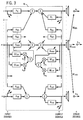
- Fig. 3 herein is like Fig. 9 of incorporated U.S. Patent 5,216,721 and shows the generalized system for n input signals from n input transducers, n output signals to n output transducers, and n error signals from n error transducers, extrapolating the above system.
- Fig. 3 shows the m th input signal from the m th input transducer providing an input to algorithm filter A lm through A km through A mm through A nm .
- Algorithm filter A mm is updated by the weight update from the sum of the outputs of respective error path models SE lm through SE nm multiplied by respective error signals e l through e n .
- Algorithm filter A km is updated by the weight update from the sum of the outputs of respective error path models SE lk through SE nk multiplied by respective error signals e l through e n .
- the model output correction signal to the m th output transducer is applied to filter model B lm , which is the recursive transfer function in the first channel model from the m th output transducer, and so on through B km through B mm through B nm .
- Algorithm filter B mm is updated by the weight update from the sum of the outputs of respective SE error path models SE lm through SE nm multiplied by respective error signals e l through e n .
- Algorithm filter B km is updated by the weight update from the sum of the outputs of respective error path models SE lk through SE nk multiplied by respective error signals e l through e n .
- the system provides a multichannel generalized active acoustic attenuation system for complex sound fields. Each of the multiple channel models is intraconnected with all other channel models. The inputs and outputs of all channel models depend on the inputs and outputs of all other channel models. The total signal to the output transducers is used as an input to all other channel models. All error signals, e.g., e l ...e n , are used to update each channel.
- each channel has its own input transducer, output transducer, and error transducer, though other combinations are possible.
- a first channel may be the path from a first input transducer to a first output transducer
- a second channel may be the path from the first input transducer to a second output transducer.
- Each channel has a channel model, and each channel model is intraconnected with each of the remaining channel models, as above described.
- the system is applicable to one or more input transducers, one or more output transducers, and one or more error transducers, and at a minimum includes at least two input signals or at least two output transducers.
- One or more input signals representing the input acoustic wave providing the input noise are provided by respective input transducers, to the adaptive filter models. Only a single input signal need be provided, and the same such input signal may be input to each of the adaptive filter models.
- Such single input signal may be provided by a single input microphone, or alternatively the input signal may be provided by a transducer such as a tachometer which provides the frequency of a periodic input acoustic wave such as from an engine or the like.
- the input signal may be provided by one or more error signals, as above noted, in the case of a periodic noise source, "Active Adaptive Sound Control In A Duct: A Computer Simulation", J.C. Burgess, Journal of Acoustic Society of America, 70(3), September 1981, pages 715-726.
- the invention is further applicable as taught in incorporated U.S. Patent 5,216,722.
- Model inputs 42, 56, 68, 80 are provided from input microphone 54.
- various combinations of input arrays can be used, including a summed array of inputs.
- the inputs can be provided from a variety of microphones, accelerometers, transformer sensors, duct sensors, optical sensors, and other types of transducers.
- the sensor or transducer outputs can be summed in a summed array or a weighted array with adaptive filtering to optimize the input signal.
- the error signals can be a summed or weighted array.
- the error signals can be derived from error microphones mounted to occupant shoulder harnesses in a vehicle, to be described. The error sum could also be summed with ceiling microphones, headrest microphones, etc., or various combinations thereof.
- the canceling speakers can be the speakers of the vehicle audio system.
- the noted zones can be in vehicles such as cars, trucks, vans, buses, trains, ships, planes, etc.
- the zones can all be in the same vehicle, or one or more zones may be in a vehicle and other zones can be remote to the vehicle, including in other vehicles.
- the invention provides a communication system including a plurality of zones subject to noise from one or more noise sources, the noise being acoustical and/or electrical, one or more speaking locations in each zone such that a person at a speaking location is subject to noise from a noise source, a plurality of speakers, each introducing sound into a respective zone at a respective speaking location, a plurality of microphones each sensing noise and speech at a respective speaking location, a plurality of adaptive filter models each canceling noise from a respective noise source, each model having a model input from a reference signal correlated to the noise from the respective noise source, each model having a plurality of error inputs, each model having an output outputting a correction signal to cancel noise from the respective noise source, such that the output of the microphone carries a speech signal from a person at the speaking location but not a noise signal from the noise source, the output of at least one microphone carrying the speech of a first person at one speaking location being supplied to at least one speaker at another speaking location, such that a second person at the
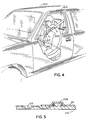
- Figs. 4 and 5 show a particularly desirable embodiment for ease of use in a vehicle.
- At least one of the noted zones is in a vehicle 202 having an occupant restraint system 204 including a shoulder harness 206.
- At least one error microphone 208 is mounted to the shoulder harness.
- the shoulder harness includes a mesh belt 210. Error microphone 208 is embedded in the mesh belt or mounted thereto by a sound-transmissive layer or tape member 211 and has a connection wire 212 running along the belt and enmeshed therein, such that the error microphone and connection wire are part of the belt.
- the error microphone is automatically positioned in a proper location upon deployment of the belt.
- wire 212 is connected to a seatbelt interlock 213, such as the seatbelt anchor, to provide feedback information confirming deployment of the belt and the presence of an occupant at the respective location.
- a wireless microphone 208 is used.
Abstract
Description
- The invention relates to multi-channel communication systems, including active acoustic attenuation systems, and vehicle applications.
- The invention arose during continuing development efforts relating to the subject matter of U.S. Patents 4,677,676, 5,033,082, 5,216,721 and 5,216,722, all incorporated herein by reference. The invention involves an intercom communication system in a multi-channel application having one or more zones subject to noise from one or more noise sources, and one or more speaking locations in each zone.
- One exemplary application of the invention is in an automobile where the front seat is a first zone and the rear seat is a second zone, and the left front passenger is in a first speaking location, the right front passenger is in a second speaking location, the left rear passenger is in a third speaking location, and the right rear passenger is in a fourth speaking location. Engine noise, road noise, etc. is canceled at each location, including cross-coupled noise between channels, but not speech from another location.
- The invention has numerous other applications where communication is desired in multi-channel noisy environments.
- Fig. 1 shows an active acoustic attenuation system in accordance with the invention.
- Fig. 2 further illustrates a portion of the system of Fig. 1.
- Fig. 3 shows a further active acoustic attenuation system.
- Fig. 4 is an isometric view, partially cut away, illustrating a further embodiment of the invention.
- Fig. 5 is a sectional view taken along line 5-5 of Fig. 4.
- Fig. 1 shows an active
acoustic attenuation system 10 including plural zones such as 12 and 14 subject to noise from one or more noise sources. There may be a single noise source such as shown at 16, or multiple noise sources for example as shown in incorporated U.S. Patent 5,033,082 at 14 and 18. Each zone includes one or more speaking locations, for example 18 and 20 inzone zone 14, such that a person at a speaking location is subject to noise from one or more noise sources.Speakers zone 12 atrespective speaking locations Speakers zone 14 atrespective speaking locations Error microphones respective speaking locations Error microphones 38 and 40 sense noise and speech atrespective speaking locations - A plurality of adaptive filter models M1, M2, M3, M4 each cancel noise from a respective noise source at a respective speaking location as sensed by a respective error microphone. Model M1 has a
model input 42 from a reference signal correlated to the noise from the respective noise source. Model M1 has a plurality oferror inputs respective error microphones output 52 outputting a correction signal to introduce canceling sound atrespective speaking location 18 to cancel noise fromrespective noise source 16, such that the output oferror microphone 34 carries a speech signal from a person atspeaking location 18 but not a noise signal fromnoise source 16. Noise fromsource 16 is sensed atinput transducer 54 provided by an input microphone which outputs a noise signal correlated to the noise. In the case of a periodic noise source, the input transducer may be provided by a tachometer or the like, or may be eliminated for example as in incorporated U.S. Patent 5,216,722. In the embodiment shown, an input microphone is preferred fortransducer 54 to sense engine noise, which is periodic but which period may change at changing engine speeds, and also to sense random noise such as road noise etc. Model M2 has amodel input 56,error inputs model output 66. Model M3 has amodel input 68,error inputs model output 78. Model M4 has amodel input 80,error inputs model output 90. Models M2, M3 and M4 may receive their model input signals from thesame transducer 54 as model M1 or from other transducers or may sense noise from other noise sources, for example as in incorporated U.S. Patent 5,033,082. In the disclosed embodiment, each of the models receives its model input signal from the same reference signal correlated to engine and road noise, and havemodel output signals front speaker 26, leftfront speaker 28, rightrear speaker 30, leftrear speaker 32 of an automobile. - The output of
error microphone 34 carrying the speech of a person atspeaking location 18 is supplied tospeakers speaking locations location 22 can hear the speech of the person atlocation 18, and a person atlocation 24 can hear the speech of the person atlocation 18. The output oferror microphone 36 carrying the speech of a person atlocation 20 is supplied tospeakers locations location 22 can hear the speech of a person atlocation 20, and a person atlocation 24 can hear the speech of a person atlocation 20. The output oferror microphone 38 carrying the speech of a person atlocation 22 is supplied tospeaker 26 atlocation 18 and tospeaker 28 atlocation 20, such that a person atlocation 18 can hear the speech of a person atlocation 22, and a person atlocation 20 can hear the speech of a person atlocation 22. The output of error microphone 40 carrying the speech of a person atlocation 24 is supplied tospeaker 26 atlocation 18 and tospeaker 28 atlocation 20, such that a person atlocation 18 can hear the speech of a person atlocation 24, and a person atlocation 20 can hear the speech of a person atlocation 24. - Each of models M1, M2, M3, M4 has an error input from each of the
error microphones error inputs error microphones model output 52 supplied tospeaker 26. Model M2 haserror inputs error microphones model output 66 supplied tospeaker 28. Model M3 haserror inputs error microphones model output 78 supplied tospeaker 30. Model M4 haserror inputs error microphones model output 90 supplied tospeaker 32. In the embodiment shown,zones common noise source 16, and models M1, M2, M3, M4 havemodel inputs input microphone 54 correlated to noise fromcommon noise source 16. Each of models M1, M2, M3, M4 is preferably an IIR (infinite impulse response) filter for example as disclosed in incorporated U.S. Patent 4,677,676, or alternatively an FIR (finite impulse response) filter, though other types of adaptive filter models may be used. - Adaptive filter model M5 has a
model input 92 receiving through summer 94 a noise signal frominput microphone 54 correlated with noise fromnoise source 16. Model M5 has amodel output 96 summed atsummer 98 with the output ofsummer 100 which sums the outputs oferror microphones error input 102 from the output ofsummer 98. Models M1 and M2 acoustically cancel noise in the respective outputs oferror microphones error microphones Summer 94 also has an input fromaudio source 104, which may for example be the audio system or the like of the automobile, to thus cancel such audio signal component in the signal supplied fromsummer 98 tospeakers locations model input 106 fromsummer 94. Model M6 has amodel output 108 summed atsummer 110 with the output ofsummer 111 which sums the outputs oferror microphones 38 and 40. Model M6 has anerror input 112 from the output ofsummer 110. Model M6 electrically cancels noise fromnoise source 16 and audio noise or sound fromsource 104 in the signal transmitted tospeakers - Model M7 has a
model input 114 from the signal fromerror microphones 38 and 40, amodel output 116 summed atsummer 118 with the output ofsummer 98, and anerror input 120 from the output ofsummer 118. Model M7 cancels the speech of a person atlocations speakers such locations model input 122 from the signal fromerror microphones model output 124 supplied tosummer 126, and anerror input 128 from the output ofsummer 126. Model M8 cancels the speech of persons atlocations speakers such locations -
Summer 130 has an input from model M1 and an input fromsummer 126, and has an output supplied tospeaker 26.Summer 132 has an input from model M2 and an input fromsummer 126, and has an output supplied tospeaker 28.Summer 134 has an input from model M3 and an input fromsummer 118, and has an output supplied tospeaker 30.Summer 136 has an input from model M4 and an input fromsummer 118, and has an output supplied tospeaker 32. - As noted above, each channel model M1, M2, M3, M4 has an error input from each of the
error microphones first error microphone 34 from thefirst speaker 26, an error path SE21 to thesecond error microphone 36 from thefirst speaker 26, an error path SE31 to thethird error microphone 38 from thefirst speaker 26, and an error path SE41 to the fourth error microphone 40 from thefirst speaker 26, i.e. betweenspeaker 26 and each oferror microphones speaker 28 to each oferror microphones speaker 30 to each oferror microphones speaker 32 to each oferror microphones M1 model input 42 is supplied through error path transfer function model SE11 at 138, Fig. 2, and multiplied atmultiplier 140 with the error signal e1 fromerror microphone 34 to provide a weight update signal tosummer 142.Model input 42 is supplied through the SE21 error path transfer function model at 144 and multiplied atmultiplier 146 with the error signal e2 fromerror microphone 36 to provide a weight update signal tosummer 142.Model input 42 is supplied through the error path SE31 transfer function model at 148 and multiplied atmultiplier 150 with error signal e3 fromerror microphone 38 to provide a weight update signal tosummer 142.Model input 42 is supplied through the error path SE41 transfer function model at 152 and multiplied atmultiplier 154 with error signal e4 from error microphone 40 to provide a weight update signal tosummer 142. The output ofsummer 142 provides the weight update signal for model M1. The multiple error signal processing for models M2, M3, M4 is comparable, and for which further reference may be had to incorporated U.S. Patents 5,216,721 and 5,216,722. - As above noted, models M1, M2, M3, M4 acoustically cancel or control noise, and models M5, M6, M7, M8 electrically cancel or control noise. Models M1, M2, M3, M4 preferably include SE modeling, as noted above, and as in incorporated U.S. Patents 5,216,721 and 5,216,722. Models M5, M6, M7, M8 do not include SE modeling. In one particularly efficient embodiment, models M1, M2, M3, M4 are performed by a first processor operating at a low sampling rate, e.g. one or two kHz, and models M5, M6, M7, M8 are performed by a second processor operating at a substantially higher sampling rate, e.g. seven to ten kHz, over a broad frequency band because of the electrical cancellation.
- The invention can be expanded to any number of channels and can be implemented by the model shown in incorporated U.S. Patent 5,216,721. Fig. 3 herein is like Fig. 9 of incorporated U.S. Patent 5,216,721 and shows the generalized system for n input signals from n input transducers, n output signals to n output transducers, and n error signals from n error transducers, extrapolating the above system. Fig. 3 shows the mth input signal from the mth input transducer providing an input to algorithm filter Alm through Akm through Amm through Anm. Algorithm filter Amm is updated by the weight update from the sum of the outputs of respective error path models SElm through SEnm multiplied by respective error signals el through en. Algorithm filter Akm is updated by the weight update from the sum of the outputs of respective error path models SElk through SEnk multiplied by respective error signals el through en. The model output correction signal to the mth output transducer is applied to filter model Blm, which is the recursive transfer function in the first channel model from the mth output transducer, and so on through Bkm through Bmm through Bnm. Algorithm filter Bmm is updated by the weight update from the sum of the outputs of respective SE error path models SElm through SEnm multiplied by respective error signals el through en. Algorithm filter Bkm is updated by the weight update from the sum of the outputs of respective error path models SElk through SEnk multiplied by respective error signals el through en. The system provides a multichannel generalized active acoustic attenuation system for complex sound fields. Each of the multiple channel models is intraconnected with all other channel models. The inputs and outputs of all channel models depend on the inputs and outputs of all other channel models. The total signal to the output transducers is used as an input to all other channel models. All error signals, e.g., el...en, are used to update each channel.
- It is preferred that each channel has its own input transducer, output transducer, and error transducer, though other combinations are possible. For example, a first channel may be the path from a first input transducer to a first output transducer, and a second channel may be the path from the first input transducer to a second output transducer. Each channel has a channel model, and each channel model is intraconnected with each of the remaining channel models, as above described. The system is applicable to one or more input transducers, one or more output transducers, and one or more error transducers, and at a minimum includes at least two input signals or at least two output transducers. One or more input signals representing the input acoustic wave providing the input noise are provided by respective input transducers, to the adaptive filter models. Only a single input signal need be provided, and the same such input signal may be input to each of the adaptive filter models. Such single input signal may be provided by a single input microphone, or alternatively the input signal may be provided by a transducer such as a tachometer which provides the frequency of a periodic input acoustic wave such as from an engine or the like. Further alternatively, the input signal may be provided by one or more error signals, as above noted, in the case of a periodic noise source, "Active Adaptive Sound Control In A Duct: A Computer Simulation", J.C. Burgess, Journal of Acoustic Society of America, 70(3), September 1981, pages 715-726. In the case of correlated input acoustic waves, the invention is further applicable as taught in incorporated U.S. Patent 5,216,722.
-
Model inputs input microphone 54. In further embodiments, various combinations of input arrays can be used, including a summed array of inputs. The inputs can be provided from a variety of microphones, accelerometers, transformer sensors, duct sensors, optical sensors, and other types of transducers. The sensor or transducer outputs can be summed in a summed array or a weighted array with adaptive filtering to optimize the input signal. Likewise, the error signals can be a summed or weighted array. The error signals can be derived from error microphones mounted to occupant shoulder harnesses in a vehicle, to be described. The error sum could also be summed with ceiling microphones, headrest microphones, etc., or various combinations thereof. The canceling speakers can be the speakers of the vehicle audio system. The noted zones can be in vehicles such as cars, trucks, vans, buses, trains, ships, planes, etc. The zones can all be in the same vehicle, or one or more zones may be in a vehicle and other zones can be remote to the vehicle, including in other vehicles. - The invention provides a communication system including a plurality of zones subject to noise from one or more noise sources, the noise being acoustical and/or electrical, one or more speaking locations in each zone such that a person at a speaking location is subject to noise from a noise source, a plurality of speakers, each introducing sound into a respective zone at a respective speaking location, a plurality of microphones each sensing noise and speech at a respective speaking location, a plurality of adaptive filter models each canceling noise from a respective noise source, each model having a model input from a reference signal correlated to the noise from the respective noise source, each model having a plurality of error inputs, each model having an output outputting a correction signal to cancel noise from the respective noise source, such that the output of the microphone carries a speech signal from a person at the speaking location but not a noise signal from the noise source, the output of at least one microphone carrying the speech of a first person at one speaking location being supplied to at least one speaker at another speaking location, such that a second person at the other speaking location can hear the speech of the first person at the one speaking location.
- Figs. 4 and 5 show a particularly desirable embodiment for ease of use in a vehicle. At least one of the noted zones is in a
vehicle 202 having anoccupant restraint system 204 including ashoulder harness 206. At least oneerror microphone 208 is mounted to the shoulder harness. The shoulder harness includes amesh belt 210.Error microphone 208 is embedded in the mesh belt or mounted thereto by a sound-transmissive layer ortape member 211 and has aconnection wire 212 running along the belt and enmeshed therein, such that the error microphone and connection wire are part of the belt. The error microphone is automatically positioned in a proper location upon deployment of the belt. In a further embodiment,wire 212 is connected to aseatbelt interlock 213, such as the seatbelt anchor, to provide feedback information confirming deployment of the belt and the presence of an occupant at the respective location. In a further alternative embodiment, awireless microphone 208 is used. - It is recognized that various equivalents, alternatives and modifications are possible within the scope of the appended claims.
Claims (27)
- A communication system comprising:
a plurality of zones subject to noise from one or more noise sources;
one or more speaking locations in each zone such that a person at a speaking location is subject to noise from a noise source;
a plurality of speakers, each introducing sound into a respective zone at a respective speaking location;
a plurality of microphones each sensing noise and speech at a respective speaking location;
a plurality of adaptive filter models each canceling noise from a respective noise source, each model having a model input from a reference signal correlated to said noise from said respective noise source, each model having a plurality of error inputs, each model having an output outputting a correction signal to cancel noise from the respective noise source, such that the output of the microphone carries a speech signal from a person at the speaking location but not a noise signal from the noise source;
the output of at least one microphone carrying the speech of a first person at one speaking location being supplied to at least one speaker at another speaking location, such that a second person at said other speaking location can hear the speech of said first person at said one speaking location. - The invention according to claim 1 comprising a first set of a plurality of adaptive filter models each acoustically canceling noise, and a second set of a plurality of adaptive filter models each electrically canceling noise.
- The invention according to claim 2 wherein said first set of models includes modeling of at least one of a respective said speaker and the respective path between the speaker and a respective microphone, and wherein said second set of models are operated at a substantially higher sampling rate than said first set of models.
- The invention according to claim 1 wherein at least one of said models has a model input from a summer summing said noise with a designated audio signal.
- The invention according to claim 1 wherein at least one of said zones is in a vehicle having an occupant restraint system including a shoulder harness, and wherein at least one of said microphones is mounted to said shoulder harness.
- The invention according to claim 1 wherein each of said zones is in a vehicle.
- The invention according to claim 6 wherein all of said zones are in the same vehicle.
- The invention according to claim 1 wherein at least one of said zones is in a vehicle, and at least another of said zones is external to said vehicle.
- An active acoustic attenuation system comprising:
a plurality of zones subject to noise from one or more noise sources;
one or more speaking locations in each zone such that a person at a speaking location is subject to noise from a noise source;
a plurality of speakers, each introducing sound into a respective zone at a respective speaking location;
a plurality of error microphones each sensing noise and speech at a respective speaking location;
a plurality of adaptive filter models each canceling noise from a respective noise source at a respective speaking location as sensed by a respective error microphone, each model having a model input from a reference signal correlated to said noise from said respective noise source, each model having a plurality of error inputs from respective error microphones, each model having an output outputting a correction signal to introduce canceling sound at the respective speaking location to cancel noise from the respective noise source, such that the output of the error microphone carries a speech signal from a person at the speaking location but not a noise signal from the noise source;
the output of at least one error microphone carrying the speech of a first person at one speaking location being supplied to at least one speaker at another speaking location, such that a second person at said other speaking location can hear the speech of said first person at said one speaking location. - The invention according to claim 9 wherein each said model has an error input from each of said error microphones.
- The invention according to claim 9 comprising:
a first said zone comprising first and second speaking locations;
a second said zone comprising third and fourth speaking locations;
a first said speaker at said first speaking location;
a second said speaker at said second speaking location;
a third said speaker at said third speaking location;
a fourth said speaker at said fourth speaking location;
a first said error microphone at said first speaking location;
a second said error microphone at said second speaking location;
a third said error microphone at said third speaking location;
a fourth said error microphone at said fourth speaking location;
a first said model having a model output to said first speaker, and first, second, third and fourth error inputs from said first, second, third and fourth error microphones, respective;
a second said model having a model output to said second speaker, and first, second, third and fourth error inputs from said first, second, third and fourth error microphones, respective;
a third said model having a model output to said third speaker, and first, second, third and fourth error inputs from said first, second, third and fourth error microphones, respective;
a fourth said model having a model output to said fourth speaker, and first, second, third and fourth error inputs from said first, second, third and fourth error microphones, respective. - The invention according to claim 11 wherein said first and second zones are subject to noise from a common noise source, and each of said first, second, third and fourth models has a model input receiving a common reference signal correlated to noise from said common noise source.
- The invention according to claim 11 comprising:
a fifth adaptive filter model;
a sixth adaptive filter model;
a seventh adaptive filter model;
an eighth adaptive filter model;
a first summer having an input from said first model, and an output supplied to said first speaker;
a second summer having an input from said second model, and an output supplied to said second speaker;
a third summer having an input from said third model, and an output supplied to said third speaker;
a fourth summer having an input from said fourth model, and an output supplied to said fourth speaker;
a fifth summer having an input from said fifth model;
a sixth summer having an input from said sixth model;
a seventh summer having an input from said seventh model;
an eighth summer having an input from said eighth model;
a ninth summer having an input from said first error microphone and another input from said second microphone, and having an output supplied to said fifth summer;
a tenth summer having an input from said third error microphone and another input from said fourth error microphone, and having an output supplied to said sixth summer;
said fifth summer having an output supplied to said seventh summer and to an error input of said fifth model;
said sixth summer having an output supplied to said eighth summer and to an error input of said sixth model;
said seventh summer having an output supplied to said third and fourth summers and to a model input of said eighth model and to an error input of said seventh model;
said eighth summer having an output supplied to said first and second summers and to a model input of said seventh model and to an error input of said eighth model. - The invention according to claim 13 wherein each said first and second zones are subject to noise from a common noise source, and each of said first, second, third, fourth, fifth and sixth models has a model input receiving a common reference signal correlated to noise from said common noise source.
- The invention according to claim 14 comprising an eleventh summer having an input from said common reference signal and another input from a designated audio signal, and having an output supplied to said model inputs of said fifth and sixth models.
- The invention according to claim 9 comprising a first set of a plurality of adaptive filter models each acoustically canceling noise, and a second set of a plurality of adaptive filter models each electrically canceling noise.
- The invention according to claim 16 wherein at least one model of said second set has a model input from a summer summing said noise with a designated audio signal to cancel said designated audio signal at the respective speaking location.
- The invention according to claim 16 wherein said first set of models includes modeling of at least one of a respective said speaker and the respective error path between the speaker and a respective said error microphone, and wherein said second set of models are operated at a substantially higher sampling rate than said first set of models.
- The invention according to claim 9 wherein at least one of said zones is in a vehicle having an occupant restraint system including a shoulder harness, and wherein at least one of said error microphones is mounted to said shoulder harness.
- The invention according to claim 9 comprising a further plurality of adaptive filter models each canceling speech of a person in one zone from the signal sent to a speaker in said one zone from an error microphone in another zone.
- The invention according to claim 9 wherein each of said zones is in a vehicle.
- The invention according to claim 21 wherein all of said zones are in the same vehicle.
- The invention according to claim 9 wherein at least one of said zones is in a vehicle, and at least another of said zones is external to said vehicle.
- An occupant restraint system for a vehicle, comprising a shoulder harness including a belt, and a communication system microphone mounted to said belt such that said microphone is part of said belt, and said microphone is automatically positioned in proper location upon deployment of said belt.
- The invention according to claim 24 further comprising a connection wire running along said belt from said microphone, such that said microphone and connection wire are part of said belt.
- The invention according to claim 25 wherein said wire is connected to a seatbelt interlock to provide feedback information confirming deployment of said belt and presence of an occupant in the respective location.
- An active acoustic attenuation system for at least partially cancelling noise in a plurality of zones in each of which a speaking person may be located, the system comprising a plurality of error microphones each for sensing noise and speech in a respective zone and a plurality of adaptive filter models each having a model input for receiving a reference signal representative of noise to be cancelled and each having error inputs from said error microphones, the models each having an output for providing a correction signal to introduce cancelling sound in a respective zone, the correction signal being such as to at least partially cancel noise in the zone without cancelling the speech of a person in that zone and to introduce into the zone the speech of a person in another zone.
Applications Claiming Priority (2)
| Application Number | Priority Date | Filing Date | Title |
|---|---|---|---|
| US368920 | 1995-01-05 | ||
| US08/368,920 US5602928A (en) | 1995-01-05 | 1995-01-05 | Multi-channel communication system |
Publications (3)
| Publication Number | Publication Date |
|---|---|
| EP0721178A2 true EP0721178A2 (en) | 1996-07-10 |
| EP0721178A3 EP0721178A3 (en) | 1998-12-09 |
| EP0721178B1 EP0721178B1 (en) | 2003-05-14 |
Family
ID=23453303
Family Applications (1)
| Application Number | Title | Priority Date | Filing Date |
|---|---|---|---|
| EP96300078A Expired - Lifetime EP0721178B1 (en) | 1995-01-05 | 1996-01-04 | Multi-channel communication system |
Country Status (4)
| Country | Link |
|---|---|
| US (1) | US5602928A (en) |
| EP (1) | EP0721178B1 (en) |
| CA (1) | CA2166572A1 (en) |
| DE (1) | DE69628061T2 (en) |
Cited By (12)
| Publication number | Priority date | Publication date | Assignee | Title |
|---|---|---|---|---|
| EP0903726A2 (en) * | 1997-09-11 | 1999-03-24 | Digisonix, Inc. | Active acoustic noise and echo cancellation system |
| DE19812697A1 (en) * | 1998-03-23 | 1999-09-30 | Volkswagen Ag | Method and device for operating a microphone arrangement, in particular in a motor vehicle |
| WO2001041499A2 (en) * | 1999-11-29 | 2001-06-07 | Deutsche Telekom Ag | Method and device for improving communication in a vehicle |
| US6549629B2 (en) | 2001-02-21 | 2003-04-15 | Digisonix Llc | DVE system with normalized selection |
| US7106866B2 (en) | 2000-04-06 | 2006-09-12 | Siemens Vdo Automotive, Inc. | Active noise cancellation stability solution |
| EP1739654A2 (en) | 1999-09-08 | 2007-01-03 | Volkswagen AG | Method for operating a multiple microphone system in a motor vehicle and multiple microphone system itself |
| EP1860911A1 (en) * | 2006-05-24 | 2007-11-28 | Harman/Becker Automotive Systems GmbH | System and method for improving communication in a room |
| WO2009012496A2 (en) * | 2007-07-19 | 2009-01-22 | Bose Corporation | System and method for directionally radiating sound |
| EP2211564A1 (en) | 2009-01-23 | 2010-07-28 | Harman Becker Automotive Systems GmbH | Passenger compartment communication system |
| EP3144928A1 (en) * | 2015-09-15 | 2017-03-22 | Harman Becker Automotive Systems GmbH | Noise and vibration sensing |
| WO2020052759A1 (en) * | 2018-09-13 | 2020-03-19 | Harman Becker Automotive Systems Gmbh | Silent zone generation |
| GB2572460B (en) * | 2018-03-28 | 2021-11-17 | Cirrus Logic Int Semiconductor Ltd | Noise suppression |
Families Citing this family (30)
| Publication number | Priority date | Publication date | Assignee | Title |
|---|---|---|---|---|
| US5706344A (en) * | 1996-03-29 | 1998-01-06 | Digisonix, Inc. | Acoustic echo cancellation in an integrated audio and telecommunication system |
| US5917920A (en) * | 1997-05-29 | 1999-06-29 | Humphries; Alan | Safety vehicle communication system |
| US6535609B1 (en) | 1997-06-03 | 2003-03-18 | Lear Automotive Dearborn, Inc. | Cabin communication system |
| US5987106A (en) * | 1997-06-24 | 1999-11-16 | Ati Technologies, Inc. | Automatic volume control system and method for use in a multimedia computer system |
| US6430295B1 (en) | 1997-07-11 | 2002-08-06 | Telefonaktiebolaget Lm Ericsson (Publ) | Methods and apparatus for measuring signal level and delay at multiple sensors |
| US6704421B1 (en) | 1997-07-24 | 2004-03-09 | Ati Technologies, Inc. | Automatic multichannel equalization control system for a multimedia computer |
| US6295364B1 (en) | 1998-03-30 | 2001-09-25 | Digisonix, Llc | Simplified communication system |
| US6055502A (en) * | 1997-09-27 | 2000-04-25 | Ati Technologies, Inc. | Adaptive audio signal compression computer system and method |
| US6674864B1 (en) | 1997-12-23 | 2004-01-06 | Ati Technologies | Adaptive speaker compensation system for a multimedia computer system |
| US6195435B1 (en) | 1998-05-01 | 2001-02-27 | Ati Technologies | Method and system for channel balancing and room tuning for a multichannel audio surround sound speaker system |
| US6438247B1 (en) * | 1999-01-28 | 2002-08-20 | International Business Machines Corporation | Seatbelt microphone mounting |
| DE19938158C1 (en) * | 1999-08-16 | 2001-01-11 | Daimler Chrysler Ag | Acoustic signal loss compensation method for automobile intercom device determines signal transmission path for providing transmission function parameter used for controlling acoustic signal level |
| ATE248497T1 (en) * | 1999-12-09 | 2003-09-15 | Frederick Johannes Bruwer | VOICE DISTRIBUTION SYSTEM |
| US20010046300A1 (en) * | 2000-04-17 | 2001-11-29 | Mclean Ian R. | Offline active control of automotive noise |
| ES2228705T3 (en) * | 2000-07-13 | 2005-04-16 | Paragon Ag | HANDS-FREE DEVICE. |
| US20020039422A1 (en) * | 2000-09-20 | 2002-04-04 | Daly Paul D. | Driving mode for active noise cancellation |
| US20020076058A1 (en) * | 2000-12-19 | 2002-06-20 | Astorino John Frank | Engine rotation reference signal for noise attenuation |
| US6594368B2 (en) | 2001-02-21 | 2003-07-15 | Digisonix, Llc | DVE system with dynamic range processing |
| US6717537B1 (en) | 2001-06-26 | 2004-04-06 | Sonic Innovations, Inc. | Method and apparatus for minimizing latency in digital signal processing systems |
| US20030112981A1 (en) * | 2001-12-17 | 2003-06-19 | Siemens Vdo Automotive, Inc. | Active noise control with on-line-filtered C modeling |
| DE102004039066B4 (en) * | 2003-09-16 | 2015-03-12 | Volkswagen Ag | Audio system for a motor vehicle |
| JP4958154B2 (en) * | 2006-11-29 | 2012-06-20 | 本田技研工業株式会社 | Motorcycle |
| US9247346B2 (en) * | 2007-12-07 | 2016-01-26 | Northern Illinois Research Foundation | Apparatus, system and method for noise cancellation and communication for incubators and related devices |
| US8135140B2 (en) | 2008-11-20 | 2012-03-13 | Harman International Industries, Incorporated | System for active noise control with audio signal compensation |
| US9020158B2 (en) * | 2008-11-20 | 2015-04-28 | Harman International Industries, Incorporated | Quiet zone control system |
| US8718289B2 (en) * | 2009-01-12 | 2014-05-06 | Harman International Industries, Incorporated | System for active noise control with parallel adaptive filter configuration |
| US8189799B2 (en) * | 2009-04-09 | 2012-05-29 | Harman International Industries, Incorporated | System for active noise control based on audio system output |
| US8199924B2 (en) * | 2009-04-17 | 2012-06-12 | Harman International Industries, Incorporated | System for active noise control with an infinite impulse response filter |
| US8077873B2 (en) * | 2009-05-14 | 2011-12-13 | Harman International Industries, Incorporated | System for active noise control with adaptive speaker selection |
| US9131915B2 (en) | 2011-07-06 | 2015-09-15 | University Of New Brunswick | Method and apparatus for noise cancellation |
Citations (5)
| Publication number | Priority date | Publication date | Assignee | Title |
|---|---|---|---|---|
| US5033082A (en) * | 1989-07-31 | 1991-07-16 | Nelson Industries, Inc. | Communication system with active noise cancellation |
| US5216721A (en) * | 1991-04-25 | 1993-06-01 | Nelson Industries, Inc. | Multi-channel active acoustic attenuation system |
| US5216722A (en) * | 1991-11-15 | 1993-06-01 | Nelson Industries, Inc. | Multi-channel active attenuation system with error signal inputs |
| US5245664A (en) * | 1989-12-29 | 1993-09-14 | Nissan Motor Company, Limited | Active noise control system for automotive vehicle |
| EP0560364A1 (en) * | 1992-03-12 | 1993-09-15 | Honda Giken Kogyo Kabushiki Kaisha | Vibration/noise control system for vehicles |
Family Cites Families (4)
| Publication number | Priority date | Publication date | Assignee | Title |
|---|---|---|---|---|
| US4677676A (en) * | 1986-02-11 | 1987-06-30 | Nelson Industries, Inc. | Active attenuation system with on-line modeling of speaker, error path and feedback pack |
| JP2921232B2 (en) * | 1991-12-27 | 1999-07-19 | 日産自動車株式会社 | Active uncomfortable wave control device |
| JPH084243B2 (en) * | 1993-05-31 | 1996-01-17 | 日本電気株式会社 | Method and apparatus for removing multi-channel echo |
| US5327496A (en) * | 1993-06-30 | 1994-07-05 | Iowa State University Research Foundation, Inc. | Communication device, apparatus, and method utilizing pseudonoise signal for acoustical echo cancellation |
-
1995
- 1995-01-05 US US08/368,920 patent/US5602928A/en not_active Expired - Lifetime
-
1996
- 1996-01-04 DE DE69628061T patent/DE69628061T2/en not_active Expired - Lifetime
- 1996-01-04 CA CA002166572A patent/CA2166572A1/en not_active Abandoned
- 1996-01-04 EP EP96300078A patent/EP0721178B1/en not_active Expired - Lifetime
Patent Citations (5)
| Publication number | Priority date | Publication date | Assignee | Title |
|---|---|---|---|---|
| US5033082A (en) * | 1989-07-31 | 1991-07-16 | Nelson Industries, Inc. | Communication system with active noise cancellation |
| US5245664A (en) * | 1989-12-29 | 1993-09-14 | Nissan Motor Company, Limited | Active noise control system for automotive vehicle |
| US5216721A (en) * | 1991-04-25 | 1993-06-01 | Nelson Industries, Inc. | Multi-channel active acoustic attenuation system |
| US5216722A (en) * | 1991-11-15 | 1993-06-01 | Nelson Industries, Inc. | Multi-channel active attenuation system with error signal inputs |
| EP0560364A1 (en) * | 1992-03-12 | 1993-09-15 | Honda Giken Kogyo Kabushiki Kaisha | Vibration/noise control system for vehicles |
Cited By (21)
| Publication number | Priority date | Publication date | Assignee | Title |
|---|---|---|---|---|
| EP0903726A3 (en) * | 1997-09-11 | 1999-07-21 | Digisonix, Inc. | Active acoustic noise and echo cancellation system |
| US6496581B1 (en) | 1997-09-11 | 2002-12-17 | Digisonix, Inc. | Coupled acoustic echo cancellation system |
| EP0903726A2 (en) * | 1997-09-11 | 1999-03-24 | Digisonix, Inc. | Active acoustic noise and echo cancellation system |
| DE19812697A1 (en) * | 1998-03-23 | 1999-09-30 | Volkswagen Ag | Method and device for operating a microphone arrangement, in particular in a motor vehicle |
| US6748088B1 (en) | 1998-03-23 | 2004-06-08 | Volkswagen Ag | Method and device for operating a microphone system, especially in a motor vehicle |
| EP1739654A2 (en) | 1999-09-08 | 2007-01-03 | Volkswagen AG | Method for operating a multiple microphone system in a motor vehicle and multiple microphone system itself |
| US7415116B1 (en) | 1999-11-29 | 2008-08-19 | Deutsche Telekom Ag | Method and system for improving communication in a vehicle |
| WO2001041499A2 (en) * | 1999-11-29 | 2001-06-07 | Deutsche Telekom Ag | Method and device for improving communication in a vehicle |
| WO2001041499A3 (en) * | 1999-11-29 | 2001-12-20 | Deutsche Telekom Ag | Method and device for improving communication in a vehicle |
| US7106866B2 (en) | 2000-04-06 | 2006-09-12 | Siemens Vdo Automotive, Inc. | Active noise cancellation stability solution |
| US6549629B2 (en) | 2001-02-21 | 2003-04-15 | Digisonix Llc | DVE system with normalized selection |
| EP1860911A1 (en) * | 2006-05-24 | 2007-11-28 | Harman/Becker Automotive Systems GmbH | System and method for improving communication in a room |
| WO2009012496A2 (en) * | 2007-07-19 | 2009-01-22 | Bose Corporation | System and method for directionally radiating sound |
| WO2009012496A3 (en) * | 2007-07-19 | 2009-03-26 | Bose Corp | System and method for directionally radiating sound |
| CN101682813B (en) * | 2007-07-19 | 2011-08-24 | 伯斯有限公司 | System and method for directionally radiating sound |
| EP2211564A1 (en) | 2009-01-23 | 2010-07-28 | Harman Becker Automotive Systems GmbH | Passenger compartment communication system |
| EP3144928A1 (en) * | 2015-09-15 | 2017-03-22 | Harman Becker Automotive Systems GmbH | Noise and vibration sensing |
| US10096314B2 (en) | 2015-09-15 | 2018-10-09 | Harman Becker Automotive Systems Gmbh | Noise and vibration sensing |
| GB2572460B (en) * | 2018-03-28 | 2021-11-17 | Cirrus Logic Int Semiconductor Ltd | Noise suppression |
| WO2020052759A1 (en) * | 2018-09-13 | 2020-03-19 | Harman Becker Automotive Systems Gmbh | Silent zone generation |
| US11495205B2 (en) | 2018-09-13 | 2022-11-08 | Harman Becker Automotive Systems Gmbh | Silent zone generation |
Also Published As
| Publication number | Publication date |
|---|---|
| DE69628061T2 (en) | 2004-04-01 |
| EP0721178B1 (en) | 2003-05-14 |
| CA2166572A1 (en) | 1996-07-06 |
| EP0721178A3 (en) | 1998-12-09 |
| US5602928A (en) | 1997-02-11 |
| DE69628061D1 (en) | 2003-06-18 |
Similar Documents
| Publication | Publication Date | Title |
|---|---|---|
| US5602928A (en) | Multi-channel communication system | |
| EP0411801B1 (en) | Communication system with active noise cancellation | |
| EP0903726B1 (en) | Active acoustic noise and echo cancellation system | |
| EP0542457B1 (en) | Multi-channel active attenuation system with error signal inputs | |
| US20020071573A1 (en) | DVE system with customized equalization | |
| EP0510864B1 (en) | Multi-channel active acoustic attenuation system | |
| US20020141601A1 (en) | DVE system with normalized selection | |
| EP2629289B1 (en) | Feedback active noise control system with a long secondary path | |
| US20200380947A1 (en) | Active noise control with feedback compensation | |
| US20030065513A1 (en) | Voice input and output apparatus | |
| JP2894035B2 (en) | Active noise control device | |
| US11250832B2 (en) | Feedforward active noise control | |
| CN111667845A (en) | Signal processing device and signal processing method | |
| JP3377220B2 (en) | Speech privacy protection device | |
| EP0655157A1 (en) | Vehicle operator station with three dimensional active noise cancellation | |
| JPH0519776A (en) | Active vibration controller | |
| EP1261961B1 (en) | Methods and systems for noise reduction for spatially displaced signal sources | |
| JPH0511779A (en) | Active noise control device | |
| JP3384493B2 (en) | Interior noise reduction device | |
| EP4057275B1 (en) | Active noise control system | |
| JP3144569B2 (en) | Vehicle noise control device | |
| JP3122192B2 (en) | Active noise control device and adaptive noise control method | |
| JPH0895579A (en) | Device for decreasing noise in vehicle room | |
| CN117877457A (en) | Intelligent cabin noise active control system and method with small calculated amount | |
| JPH07199965A (en) | Adaptive active silencer for vehicle interior sound |
Legal Events
| Date | Code | Title | Description |
|---|---|---|---|
| PUAI | Public reference made under article 153(3) epc to a published international application that has entered the european phase |
Free format text: ORIGINAL CODE: 0009012 |
|
| AK | Designated contracting states |
Kind code of ref document: A2 Designated state(s): DE FR GB IT NL SE |
|
| PUAL | Search report despatched |
Free format text: ORIGINAL CODE: 0009013 |
|
| AK | Designated contracting states |
Kind code of ref document: A3 Designated state(s): DE FR GB IT NL SE |
|
| 17P | Request for examination filed |
Effective date: 19990512 |
|
| 17Q | First examination report despatched |
Effective date: 20010928 |
|
| GRAH | Despatch of communication of intention to grant a patent |
Free format text: ORIGINAL CODE: EPIDOS IGRA |
|
| GRAH | Despatch of communication of intention to grant a patent |
Free format text: ORIGINAL CODE: EPIDOS IGRA |
|
| GRAA | (expected) grant |
Free format text: ORIGINAL CODE: 0009210 |
|
| AK | Designated contracting states |
Designated state(s): DE FR GB IT NL SE |
|
| PG25 | Lapsed in a contracting state [announced via postgrant information from national office to epo] |
Ref country code: NL Free format text: LAPSE BECAUSE OF FAILURE TO SUBMIT A TRANSLATION OF THE DESCRIPTION OR TO PAY THE FEE WITHIN THE PRESCRIBED TIME-LIMIT Effective date: 20030514 Ref country code: IT Free format text: LAPSE BECAUSE OF FAILURE TO SUBMIT A TRANSLATION OF THE DESCRIPTION OR TO PAY THE FEE WITHIN THE PRESCRIBED TIME-LIMIT;WARNING: LAPSES OF ITALIAN PATENTS WITH EFFECTIVE DATE BEFORE 2007 MAY HAVE OCCURRED AT ANY TIME BEFORE 2007. THE CORRECT EFFECTIVE DATE MAY BE DIFFERENT FROM THE ONE RECORDED. Effective date: 20030514 Ref country code: FR Free format text: LAPSE BECAUSE OF FAILURE TO SUBMIT A TRANSLATION OF THE DESCRIPTION OR TO PAY THE FEE WITHIN THE PRESCRIBED TIME-LIMIT Effective date: 20030514 |
|
| REG | Reference to a national code |
Ref country code: GB Ref legal event code: FG4D |
|
| REF | Corresponds to: |
Ref document number: 69628061 Country of ref document: DE Date of ref document: 20030618 Kind code of ref document: P |
|
| PG25 | Lapsed in a contracting state [announced via postgrant information from national office to epo] |
Ref country code: SE Free format text: LAPSE BECAUSE OF FAILURE TO SUBMIT A TRANSLATION OF THE DESCRIPTION OR TO PAY THE FEE WITHIN THE PRESCRIBED TIME-LIMIT Effective date: 20030814 |
|
| NLV1 | Nl: lapsed or annulled due to failure to fulfill the requirements of art. 29p and 29m of the patents act | ||
| PLBE | No opposition filed within time limit |
Free format text: ORIGINAL CODE: 0009261 |
|
| STAA | Information on the status of an ep patent application or granted ep patent |
Free format text: STATUS: NO OPPOSITION FILED WITHIN TIME LIMIT |
|
| 26N | No opposition filed |
Effective date: 20040217 |
|
| EN | Fr: translation not filed | ||
| PGFP | Annual fee paid to national office [announced via postgrant information from national office to epo] |
Ref country code: DE Payment date: 20150128 Year of fee payment: 20 |
|
| PGFP | Annual fee paid to national office [announced via postgrant information from national office to epo] |
Ref country code: GB Payment date: 20150127 Year of fee payment: 20 |
|
| REG | Reference to a national code |
Ref country code: DE Ref legal event code: R071 Ref document number: 69628061 Country of ref document: DE |
|
| REG | Reference to a national code |
Ref country code: GB Ref legal event code: PE20 Expiry date: 20160103 |
|
| PG25 | Lapsed in a contracting state [announced via postgrant information from national office to epo] |
Ref country code: GB Free format text: LAPSE BECAUSE OF EXPIRATION OF PROTECTION Effective date: 20160103 |