EP0723218A2 - Arithmetic processing apparatus and method used thereby - Google Patents

Arithmetic processing apparatus and method used thereby Download PDF

Info

Publication number
EP0723218A2
EP0723218A2 EP96103447A EP96103447A EP0723218A2 EP 0723218 A2 EP0723218 A2 EP 0723218A2 EP 96103447 A EP96103447 A EP 96103447A EP 96103447 A EP96103447 A EP 96103447A EP 0723218 A2 EP0723218 A2 EP 0723218A2
Authority
EP
European Patent Office
Prior art keywords
value
place
interim
approximate
solution
Prior art date
Legal status (The legal status is an assumption and is not a legal conclusion. Google has not performed a legal analysis and makes no representation as to the accuracy of the status listed.)
Withdrawn
Application number
EP96103447A
Other languages
German (de)
French (fr)
Other versions
EP0723218A3 (en
Inventor
Takashi Taniguchi
Current Assignee (The listed assignees may be inaccurate. Google has not performed a legal analysis and makes no representation or warranty as to the accuracy of the list.)
Panasonic Holdings Corp
Original Assignee
Matsushita Electric Industrial Co Ltd
Priority date (The priority date is an assumption and is not a legal conclusion. Google has not performed a legal analysis and makes no representation as to the accuracy of the date listed.)
Filing date
Publication date
Application filed by Matsushita Electric Industrial Co Ltd filed Critical Matsushita Electric Industrial Co Ltd
Publication of EP0723218A2 publication Critical patent/EP0723218A2/en
Publication of EP0723218A3 publication Critical patent/EP0723218A3/en
Withdrawn legal-status Critical Current

Links

Images

Classifications

    • GPHYSICS
    • G06COMPUTING; CALCULATING OR COUNTING
    • G06FELECTRIC DIGITAL DATA PROCESSING
    • G06F7/00Methods or arrangements for processing data by operating upon the order or content of the data handled
    • GPHYSICS
    • G06COMPUTING; CALCULATING OR COUNTING
    • G06FELECTRIC DIGITAL DATA PROCESSING
    • G06F7/00Methods or arrangements for processing data by operating upon the order or content of the data handled
    • G06F7/38Methods or arrangements for performing computations using exclusively denominational number representation, e.g. using binary, ternary, decimal representation
    • G06F7/48Methods or arrangements for performing computations using exclusively denominational number representation, e.g. using binary, ternary, decimal representation using non-contact-making devices, e.g. tube, solid state device; using unspecified devices
    • G06F7/52Multiplying; Dividing
    • G06F7/535Dividing only
    • GPHYSICS
    • G06COMPUTING; CALCULATING OR COUNTING
    • G06FELECTRIC DIGITAL DATA PROCESSING
    • G06F7/00Methods or arrangements for processing data by operating upon the order or content of the data handled
    • G06F7/02Comparing digital values
    • G06F7/026Magnitude comparison, i.e. determining the relative order of operands based on their numerical value, e.g. window comparator
    • GPHYSICS
    • G06COMPUTING; CALCULATING OR COUNTING
    • G06FELECTRIC DIGITAL DATA PROCESSING
    • G06F7/00Methods or arrangements for processing data by operating upon the order or content of the data handled
    • G06F7/38Methods or arrangements for performing computations using exclusively denominational number representation, e.g. using binary, ternary, decimal representation
    • G06F7/48Methods or arrangements for performing computations using exclusively denominational number representation, e.g. using binary, ternary, decimal representation using non-contact-making devices, e.g. tube, solid state device; using unspecified devices
    • G06F7/544Methods or arrangements for performing computations using exclusively denominational number representation, e.g. using binary, ternary, decimal representation using non-contact-making devices, e.g. tube, solid state device; using unspecified devices for evaluating functions by calculation
    • G06F7/552Powers or roots, e.g. Pythagorean sums
    • G06F7/5525Roots or inverse roots of single operands
    • GPHYSICS
    • G06COMPUTING; CALCULATING OR COUNTING
    • G06FELECTRIC DIGITAL DATA PROCESSING
    • G06F2207/00Indexing scheme relating to methods or arrangements for processing data by operating upon the order or content of the data handled
    • G06F2207/535Indexing scheme relating to groups G06F7/535 - G06F7/5375
    • G06F2207/5355Using iterative approximation not using digit recurrence, e.g. Newton Raphson or Goldschmidt
    • GPHYSICS
    • G06COMPUTING; CALCULATING OR COUNTING
    • G06FELECTRIC DIGITAL DATA PROCESSING
    • G06F2207/00Indexing scheme relating to methods or arrangements for processing data by operating upon the order or content of the data handled
    • G06F2207/535Indexing scheme relating to groups G06F7/535 - G06F7/5375
    • G06F2207/5356Via reciprocal, i.e. calculate reciprocal only, or calculate reciprocal first and then the quotient from the reciprocal and the numerator
    • GPHYSICS
    • G06COMPUTING; CALCULATING OR COUNTING
    • G06FELECTRIC DIGITAL DATA PROCESSING
    • G06F7/00Methods or arrangements for processing data by operating upon the order or content of the data handled
    • G06F7/38Methods or arrangements for performing computations using exclusively denominational number representation, e.g. using binary, ternary, decimal representation
    • G06F7/48Methods or arrangements for performing computations using exclusively denominational number representation, e.g. using binary, ternary, decimal representation using non-contact-making devices, e.g. tube, solid state device; using unspecified devices
    • G06F7/483Computations with numbers represented by a non-linear combination of denominational numbers, e.g. rational numbers, logarithmic number system or floating-point numbers
    • G06F7/487Multiplying; Dividing
    • G06F7/4873Dividing
    • GPHYSICS
    • G06COMPUTING; CALCULATING OR COUNTING
    • G06FELECTRIC DIGITAL DATA PROCESSING
    • G06F7/00Methods or arrangements for processing data by operating upon the order or content of the data handled
    • G06F7/38Methods or arrangements for performing computations using exclusively denominational number representation, e.g. using binary, ternary, decimal representation
    • G06F7/48Methods or arrangements for performing computations using exclusively denominational number representation, e.g. using binary, ternary, decimal representation using non-contact-making devices, e.g. tube, solid state device; using unspecified devices
    • G06F7/499Denomination or exception handling, e.g. rounding or overflow
    • G06F7/49942Significance control
    • G06F7/49947Rounding
    • G06F7/49952Sticky bit
    • GPHYSICS
    • G06COMPUTING; CALCULATING OR COUNTING
    • G06FELECTRIC DIGITAL DATA PROCESSING
    • G06F7/00Methods or arrangements for processing data by operating upon the order or content of the data handled
    • G06F7/38Methods or arrangements for performing computations using exclusively denominational number representation, e.g. using binary, ternary, decimal representation
    • G06F7/48Methods or arrangements for performing computations using exclusively denominational number representation, e.g. using binary, ternary, decimal representation using non-contact-making devices, e.g. tube, solid state device; using unspecified devices
    • G06F7/499Denomination or exception handling, e.g. rounding or overflow
    • G06F7/49942Significance control
    • G06F7/49947Rounding
    • G06F7/49957Implementation of IEEE-754 Standard

Definitions

  • This invention relates to an apparatus for arithmetic processing, and the method used by the apparatus.
  • Some arithmetic processing apparatuses use convergence-type arithmetic operations which can derive a solution of a functional equation at a high speed. For example, division and calculation of a square root can be performed by repeating additions and multiplications in accordance with Newton's method.
  • the rounding is of various types.
  • IEEE754 floating-point standards prescribe the following four rounding modes: “round to nearest”, “round toward +infinity”, “round toward -infinity”, and “round toward zero”.
  • Accurately rounding requires information representing good values of digits in places equal to and above the place immediately lower than the lowest place of significant digits, and also information representing whether or not values of digits in places equal to and below the place lower than the lowest place of the significant digits by two places are zero.
  • a maximal error can be predicted by a calculation algorithm and a used hardware, an error between the approximate solution value and an infinitely precise value can not be known.
  • cases related to the approximate solution value and the infinitely precise value respectively may be different from each other in information representing values of digits in places equal to and above the place immediately lower than the lowest place of significant digits and also representing whether or not values of digits in places equal to and below the place lower than the lowest place of the significant digits by two places are zero.
  • This means that a result obtained by directly rounding an approximate solution value is sometimes different from a result obtained by rounding an infinitely precise value.
  • the accuracy of the approximate solution value is increased, there is a less possibility that the result obtained by rounding the approximate solution value is different from the result obtained by rounding the infinitely precise value.
  • increasing the accuracy of the approximate solution value needs a longer calculation time or a larger number of digits handled by a hardware.
  • a first aspect of this invention provides an apparatus comprising: means for generating a plurality of partial products from a given multiplicand X and a given multiplier Y; means for generating a sign inversion value from at least a lower part of a subtrahend Z to enable place matching, the sign inversion value being expressed in a format the same as a form of expression of the partial products; means for adding the partial products and the sign inversion value; and means for detecting which of the subtrahend Z and the product of the given multiplicand X and the given multiplier Y is greater in response to a result of said adding by the adding means.
  • a second aspect of this invention provides a method comprising the steps of: generating a plurality of partial products from a given multiplicand and a given multiplier; generating a sign inversion value from at least a lower part of a subtrahend to enable place matching, the sign inversion value being expressed in a format the same as a format of expression of the partial products; adding the partial products and the sign inversion value; and detecting which of the subtrahend Z and the product of the given multiplicand X and the given multiplier Y is greater in response to a result of the addition.
  • a first step 101 executes a process of calculating an approximate value. Specifically, the step 101 executes approximate calculation of a given function F(X) with respect to a given value X.
  • An approximate solution of the function F(X) is calculated by a suitable way such as Newton's method. This calculation is realized by using multipliers and adders. In this calculation, the approximate solution is determined at an accuracy where the error between the approximate solution and the infinitely precise solution is smaller than the weight of the digit in a place which is lower than the lowest place of the required significant digits for a final result by two places.
  • the number of significant digits of a mantissa part is 53, and the significant digit in the highest place has a weight of 2 0 and the significant digit in the lowest place has a weight of 2 -52 .
  • the error between the mantissa part Ya of the approximate solution and the mantissa part Y of the infinitely precise solution satisfies the following relation.
  • Fig. 2 shows an example of a number line. In Fig.
  • one or more of the digits of the approximate solution Ya are located in places lower than the place corresponding to the maximal error, that is, the place having a weight of 2 -54 .
  • the place having a weight of 2 -54 is sometimes shortened to "the place of 2 -54 " or "the 2 -54 place” in the following description. Other places are similarly shortened. It is known from the equation (3) that the approximate solution Ya lies in a region 200 of 2 -53 which is defined between points 202 and 203.
  • a step 102 rounds the approximate value Ya given by the step 101, and thereby calculates an interim solution Yr from the approximate value Ya.
  • the interim solution Yr agrees with one of possible interim solutions which is closest to the approximate solution Ya, and each of the possible interim solutions can be represented by digits whose number is larger than the number of the significant digits and whose places are higher than the place corresponding to the minimal weight greater than the maximal error of the approximate solution Ya.
  • the interim solution Yr is equal to one of possible interim solutions which is closest to the approximate solution Ya and the possible interim solutions are represented by digits in places, the lowest of which is arbitrarily selected from a place range starting from a place lower than the lowest place of the significant digits for the final solution by at least one place and ending at a place higher than a place of a minimal weight by at least one place, and a weight of digit in the minimal-weight place is greater than a maximum of an error of the approximate solution Ya.
  • the interim solution Yr agrees with a point 204 or a point 205.
  • the interim solution Yr agrees with the point 204.
  • the error between the infinitely precise value Y and the interim solution Yr satisfies the following relation.
  • the interim solution Yr is represented by digits in places, the lowest of which is lower than the lowest place of the significant digits by one place.
  • a step 103 following the step 102 calculates an inverse function value Xr from the interim solution Yr.
  • a step 104 following the step 103 compares the inverse function value Xr and the given value X.
  • the interim solution Yr equals the infinitely precise value Y.
  • a step 106 is executed after the step 104.
  • the step 106 sets a sticky digit S to 0.
  • the inverse function value Xr and the given value X are different, there is an error between the interim solution Yr and the infinitely precise value Y.
  • a step 105 is executed after the step 104.
  • the step 105 decides whether the error of the interim solution Yr lies at a higher side or a lower side of the infinitely precise value Y.
  • the step 105 will be described in detail.
  • the step 105 decides which of the infinitely precise value Y and the interim solution Yr is larger on the basis of the relation between the magnitudes of the given value X and the inverse function value Xr, and also on the basis of the characteristics of the function F.
  • the decision by the step 105 can be easily executed by referring to the relation between the magnitudes of the given value X and the inverse function value Xr.
  • the infinitely precise value Y is greater and smaller than the interim solution Yr when the given value X is greater and smaller than the inverse function value Xr respectively.
  • a step 107 is executed next.
  • the step 107 sets the sticky digit S to -1.
  • a step 108 is executed next.
  • the step 108 sets the sticky digit S to 1. In the example of Fig. 2, the sticky digit S is set to 1 and -1 when the interim solution Yr agrees with the point 204 and the point 205 respectively.
  • a final step 109 is executed.
  • the step 109 adds the sticky digit S to a place immediately lower than the lowest place of the digits of the interim solution Yr, and thus performs the addition "Yr+2 -54 S".
  • the step 109 rounds the result of the addition to the significant digits in a designated rounding mode and thereby derives a final calculation result Ye.
  • the data which represent the result of the addition have digits whose number is larger than the number of the significant digits by 2. In Fig. 2, the data are denoted by the point 206. As understood from Fig.
  • the point 206 and the infinitely precise value 201 lie between points 204 and 207 which are different only in the lowest-place significant digit by 1
  • the point 206 and the infinitely precise value 201 lie at a common side of the middle point 205 between the points 204 and 207.
  • the result of rounding the point 206 to the significant digits is equal to the result of rounding the infinitely precise value 201 (the infinitely precise value Y) to the significant digits.
  • Fig. 3 shows an apparatus for executing the arithmetic processing of Fig. 1.
  • the apparatus includes selectors 501, 503, and 504, a function calculating device 502, an adding/subtracting rounding circuit 505, a register 506, and a sticky digit generator 507.
  • selectors 501, 503, and 504 the apparatus includes selectors 501, 503, and 504, a function calculating device 502, an adding/subtracting rounding circuit 505, a register 506, and a sticky digit generator 507.
  • these devices 501-507 are controlled by a controller (not shown).
  • Data of a given value X are selected by the selector 501 and are transmitted to the function calculating device 502.
  • the function calculating device 502 executes approximate calculation of a function F with respect to the given value X, thereby calculating an approximate solution Ya. In this way, the operation of the step 101 of Fig. 1 is executed by the function calculating device 502.
  • Data of the approximate solution Ya are outputted from the function calculating device 502 to the selector 503.
  • the data of the approximate solution Ya are selected by the selector 503, and are transmitted to the adding/subtracting rounding circuit 505.
  • data of "0" are selected by the selector 504, and are transmitted to the adding/subtracting rounding circuit 505.
  • the adding/subtracting rounding circuit 505 rounds the approximate solution Ya to an interim solution Yr. In this way, the operation of the step 102 of Fig. 1 is executed by the adding/subtracting rounding circuit 505.
  • the adding/subtracting rounding circuit 505 outputs data of the interim solution Yr which are stored into the register 506.
  • the data of the interim solution Yr are selected by the selector 501, and are transmitted to the function calculating device 502.
  • the function calculating device 502 outputs data of the inverse function value Xr to the selector 503.
  • the data of the inverse function value Xr are selected by the selector 503, and are transmitted to the adding/subtracting rounding circuit 505.
  • the data of the given value X are selected by the selector 504, and are transmitted to the adding/subtracting rounding circuit 505.
  • the adding/subtracting rounding circuit 505 includes a subtracter which subtracts the given value X from the inverse function value Xr and thus which derives a difference equal to "Xr-X". Data of the difference "Xr-X" are outputted from the adding/subtracting rounding circuit 505 to the sticky digit generator 507.
  • the sticky digit generator 507 outputs data representing a sticky digit S equal to 0.
  • the sticky digit generator 507 executes a decision as to which of the infinitely precise solution Y and the interim solution Yr is greater on the basis of the characteristics of the function F and the information of the sign of the difference "Xr-X".
  • the sticky digit generator 507 outputs data representing the sticky digit S equal to -1.
  • the sticky digit generator 507 outputs data representing the sticky digit S equal to 1. In this way, the operations of the steps 104-108 of Fig. 1 are executed by the adding/subtracting rounding circuit 505 and the sticky digit generator 507.
  • the data of the sticky digit S are fed from the sticky digit generator 507 to the adding/subtracting rounding circuit 505.
  • the data of the interim solution Yr which are outputted from the register 506 are selected by the selector 503, and are transmitted to the adding/subtracting rounding circuit 505.
  • the adding/subtracting rounding circuit 505 includes an adder which adds the sticky digit S to the place immediately lower than the lowest place of the digits of the interim solution Yr.
  • the adding/subtracting rounding circuit 505 rounds the result of this addition in a designated rounding mode to obtain a final solution Ye. In this way, the operation of the step 109 of Fig. 1 is executed by the adding/subtracting rounding circuit 505.
  • Data (a digital signal) of the final solution Ye are transmitted from the adding/subtracting rounding circuit 505 to an external circuit (not shown) and are used therein.
  • a second embodiment of this invention relates to division and uses IEEE754 standards.
  • a description will be given of a normalized mantissa part.
  • a mantissa part has 53 significant digits, and the significant digit in the highest place has a weight of 2 0 and the significant digit in the lowest place has a weight of 2 -52 .
  • the numbers X and Y satisfy the relation "1 ⁇ X, Y ⁇ 2".
  • a first step 301 calculates an approximate quotient Za of division of X/Y in a suitable way such as Newton's method.
  • the step 301 corresponds to the step 101 of Fig. 1. It is now assumed that the dividend X is not smaller than the divisor Y. In this case, the infinitely precise quotient Z which equals X/Y satisfies the relation "1 ⁇ Z ⁇ 2". The accuracy of the approximate quotient Za is defined by the error between the approximate quotient Za and the infinitely precise quotient Z.
  • the error between the approximate quotient Za and the infinitely precise quotient Z is smaller than the weight of the digit in a place which is lower than the lowest place of the required significant digits for a final result by two places.
  • the error between the approximate quotient Za and the infinitely precise quotient Z satisfies the following relation.
  • ⁇ 2 -54 A step 302 following the step 301 executes rounding similar to the rounding executed by the step 102 of Fig. 1.
  • the step 302 rounds the approximate quotient Za given by the step 301, and thereby calculates an interim quotient Zr from the approximate quotient Za.
  • the interim quotient Zr agrees with one of possible interim quotients which is closest to the approximate quotient Za, and each of the possible interim quotients can be represented by digits whose number is larger than the number of the significant digits and whose places are higher than the place corresponding to the minimal weight greater than the maximal error of the approximate quotient Za.
  • the interim quotient Zr is equal to one of possible interim quotients which is closest to the approximate quotient Za and the possible interim quotients are represented by digits in places, the lowest of which is arbitrarily selected from a place range starting from a place lower than the lowest place of the significant digits for the final quotient by at least one place and ending at a place higher than a place of a minimal weight by at least one place, and a weight of digit in the minimal-weight place is greater than a maximum of an error of the approximate quotient Za.
  • the error between the infinitely precise quotient Z and the interim quotient Zr satisfies the following relation.
  • the interim quotient Zr is represented by digits in places, the lowest of which is lower than the lowest place of the significant digits by one place.
  • a step 304 following the step 303 corresponds to the steps 104 and 105 of Fig. 1. Specifically, the step 304 compares the product Xr and the given value X to decide whether the error of the interim quotient Zr lies at the lower side or the higher side of the infinitely precise quotient Z. Since both of the given values X and Y are positive and thus the infinitely precise quotient Z corresponds to a monotonically increasing function of the given value X in the division "X/Y", a sticky digit S can be determined only by the comparison between the given value X and the product Xr.
  • the step 304 is followed by a step 305 which sets the sticky digit S to -1.
  • the step 304 is followed by a step 306 which sets the sticky digit S to 0.
  • the step 304 is followed by a step 307 which sets the sticky digit S to 1.
  • a final step 308 is executed.
  • the step 308 executes rounding similar to the rounding executed by the step 109 of Fig. 1. Specifically, the step 308 adds the sticky digit S to a place immediately lower than the lowest place of the digits of the interim quotient Zr, and thus performs the addition "Zr+2 -54 S".
  • the step 308 rounds the result of the addition to the significant digits in a designated rounding mode and thereby derives a final calculation result Ze.
  • the final result Ze is equal to the result of rounding the infinitely precise quotient Z.
  • the error between the approximate quotient Za and the infinitely precise quotient Z satisfies the following relation.
  • the interim quotient Zr requires 55 digits or more in places equal to and above the 2 -54 place. Accordingly, the interim quotient Zr is calculated so that the following relation can be satisfied.
  • the step 308 rounds the result of the addition to the significant digits in the places equal to and above the 2 -53 place.
  • the interim quotient Zr may be calculated at an accuracy higher by one digit so that the equation (8) can be satisfied.
  • Fig. 5 shows an apparatus for executing the arithmetic processing of Fig. 4.
  • the apparatus includes an X register 601, a Y register 602, a T register 611, a ROM 603, selectors 604, 605, 608, and 609, a multiplier circuit 606, a constant generator 607, an adding/subtracting rounding circuit 610, a sticky digit generator 612, and data buses 613 and 614.
  • the devices 601-612 are controlled by a controller (not shown).
  • the data of the approximate quotient Za are selected by the selector 608, and are transmitted to the adding/subtracting rounding circuit 610.
  • the data of "0" are selected by the selector 609, and are transmitted to the adding/subtracting rounding circuit 610.
  • the adding/subtracting rounding circuit 610 rounds the approximate quotient Za to an interim quotient Zr.
  • the adding/subtracting rounding circuit 610 outputs data of the interim quotient Zr which are stored into the T register 611. In this way, the operation of the step 302 of Fig. 4 is executed by the adding/subtracting rounding circuit 610.
  • the data of the interim quotient Zr are transmitted to the multiplier circuit 606 via the data bus 613 and the selector 604.
  • the data of the divisor Y are transmitted to the multiplier circuit 606 via the data bus 614 and the selector 605.
  • the multiplier circuit 606 outputs data of the product Xr to the selector 608. In this way, the operation of the step 303 of Fig. 4 is executed by the multiplier circuit 606.
  • the data of the product Xr are selected by the selector 608, and are transmitted to the adding/subtracting rounding circuit 610.
  • the data of the dividend X are transmitted from the X register 601 to the adding/subtracting rounding circuit 610 via the data bus 614 and the selector 609.
  • the adding/subtracting rounding circuit 610 includes a subtracter which subtracts the dividend X from the product Xr and thus which derives a difference equal to "Xr-X".
  • Data of the difference "Xr-X" are outputted from the adding/subtracting rounding circuit 610 to the sticky digit generator 612. In the case where the difference "Xr-X" is 0, the sticky digit generator 612 outputs data representing a sticky digit S equal to 0.
  • the sticky digit generator 612 In the case where the difference "Xr-X" is negative, the sticky digit generator 612 outputs data representing the sticky digit S equal to 1. In the case where the difference "Xr-X" is positive, the sticky digit generator 612 outputs data representing the sticky digit S equal to -1. In this way, the operations of the steps 304-307 of Fig. 4 are executed by the adding/subtracting rounding circuit 610 and the sticky digit generator 612.
  • the data of the sticky digit S are fed from the sticky digit generator 612 to the adding/subtracting rounding circuit 610.
  • the data of the interim quotient Zr which are outputted from the T register 611 are selected by the selector 608, and are transmitted to the adding/subtracting rounding circuit 610.
  • the adding/subtracting rounding circuit 610 includes an adder which adds the sticky digit S to the place immediately lower than the lowest place of the digits of the interim quotient Zr.
  • the adding/subtracting rounding circuit 610 rounds the result of this addition in a designated rounding mode to obtain a final quotient Ze. In this way, the operation of the step 308 of Fig. 4 is executed by the adding/subtracting rounding circuit 610.
  • Data (a digital signal) of the final quotient Ze are transmitted from the adding/subtracting rounding circuit 610 to an external circuit (not shown), and are used therein.
  • the sticky digit S is set to 0 when the product Xr and the dividend X are equal and the sticky digit S is set to -1 and 1 when the value Xr is greater and smaller than the value X respectively.
  • the sticky digit S is set to 0 when the product Xr and the dividend X are equal and the sticky digit S is set to 1 and -1 when the value Xr is greater and smaller than the value X respectively.
  • a third embodiment of this invention relates to calculation of a square root and uses IEEE754 standards.
  • a description will be given of a normalized mantissa part.
  • a mantissa part has 53 significant digits, and the significant digit in the highest place has a weight of 2 0 and the significant digit in the lowest place has a weight of 2 -52 .
  • a first step 401 calculates an approximate square root Ya of a given value X in a suitable way such as Newton's method.
  • the step 401 corresponds to the step 101 of Fig. 1.
  • the error between the approximate square root Ya and the infinitely precise square root Y is smaller than the weight of the digit in a place which is lower than the lowest place of the required significant digits for a final result by two places.
  • step 402 following the step 401 executes rounding similar to the rounding executed by the step 102 of Fig. 1. Specifically , the step 402 rounds the approximate square root Ya given by the step 301, and thereby calculates an interim square root Yr from the approximate square root Ya.
  • the interim square root Yr agrees with one of possible interim square roots which is closest to the approximate square root Ya, and each of the possible interim square roots can be represented by digits whose number is larger than the number of the significant digits and whose places are higher than the place corresponding to the minimal weight greater than the maximal error of the approximate square root Ya.
  • the interim square root Yr is equal to one of possible interim square roots which is closest to the approximate square root Ya and the possible interim square roots are represented by digits in places, the lowest of which is arbitrarily selected from a place range starting from a place lower than the lowest place of the significant digits for the final square root by at least one place and ending at a place higher than a place of a minimal weight by at least one place, and a weight of digit in the minimal-weight place is greater than a maximum of an error of the approximate square root Ya.
  • the error between the infinitely precise square root Y and the interim square root Yr satisfies the following relation.
  • the interim square root Yr is represented by digits in places, the lowest of which is lower than the lowest place of the significant digits by one place.
  • the step 404 is followed by a step 405 which sets the sticky digit S to -1.
  • the step 404 is followed by a step 406 which sets the sticky digit S to 0.
  • the step 404 is followed by a step 407 which sets the sticky digit S to 1.
  • a final step 408 is executed.
  • the step 408 executes rounding similar to the rounding executed by the step 109 of Fig. 1. Specifically, the step 408 adds the sticky digit S to a place immediately lower than the lowest place of the digits of the interim square root Yr, and thus performs the addition "Yr+2 -54 S".
  • the step 408 rounds the result of the addition to the significant digits in a designated rounding mode and thereby derives a final calculation result Ye.
  • the final result Ye is equal to the result of rounding the infinitely precise square root Y.
  • An apparatus for executing the arithmetic processing of Fig. 6 is similar to the apparatus of Fig. 5.
  • the apparatus operates as follows.
  • the data of the approximate square root Ya are selected by the selector 608, and are transmitted to the adding/subtracting rounding circuit 610.
  • the data of "0" are selected. by the selector 609, and are transmitted to the adding/subtracting rounding circuit 610.
  • the adding/subtracting rounding circuit 610 rounds the approximate square root Ya to an interim square root Yr.
  • the adding/subtracting rounding circuit 610 outputs data of the interim square root Yr which are stored into the T register 611. In this way, the operation of the step 402 of Fig. 6 is executed by the adding/subtracting rounding circuit 610.
  • the data of the interim square root Yr are transmitted to the multiplier circuit 606 via both of the selectors 604 and 605.
  • the multiplier circuit 606 outputs data of the square Xr to the selector 608. In this way, the operation of the step 403 of Fig. 6 is executed by the multiplier circuit 606.
  • the data of the square Xr are selected by the selector 608, and are transmitted to the adding/subtracting rounding circuit 610.
  • the data of the given value X are transmitted from the X register 601 to the adding/subtracting rounding circuit 610 via the data bus 614 and the selector 609.
  • the adding/subtracting rounding circuit 610 includes a subtracter which subtracts the given value X from the square Xr and thus which derives a difference equal to "Xr-X".
  • Data of the difference "Xr-X" are outputted from the adding/subtracting rounding circuit 610 to the sticky digit generator 612. In the case where the difference "Xr-X" is 0, the sticky digit generator 612 outputs data representing a sticky digit S equal to 0.
  • the sticky digit generator 612 In the case where the difference "Xr-X" is negative, the sticky digit generator 612 outputs data representing the sticky digit S equal to 1. In the case where the difference "Xr-X" is positive, the sticky digit generator 612 outputs data representing the sticky digit S equal to -1. In this way, the operations of the steps 404-407 of Fig. 6 are executed by the adding/subtracting rounding circuit 610 and the sticky digit generator 612.
  • the data of the sticky digit S are fed from the sticky digit generator 612 to the adding/subtracting rounding circuit 610.
  • the data of the interim square root Yr which are outputted from the T register 611 are selected by the selector 608, and are transmitted to the adding/subtracting rounding circuit 610.
  • the adding/subtracting rounding circuit 610 includes an adder which adds the sticky digit S to the place immediately lower than the lowest place of the digits of the interim square root Yr.
  • the adding/subtracting rounding circuit 610 rounds the result of this addition in a designated rounding mode to obtain a final square root Ye. In this way, the operation of the step 408 of Fig. 4 is executed by the adding/subtracting rounding circuit 610.
  • Data (a digital signal) of the final square root Ye are transmitted from the adding/subtracting rounding circuit 610 to an external circuit (not shown), and are used therein.
  • a fourth embodiment of this invention is similar to the embodiment of Figs. 4 and 5 except for a design indicated hereinafter.
  • the fourth embodiment relates to division and uses IEEE754 standards.
  • a description will be given of a normalized mantissa part.
  • a mantissa part has 53 significant digits, and the significant digit in the highest place has a weight of 2 0 and the significant digit in the lowest place has a weight of 2 -52 .
  • the numbers X and Y satisfy the relation "1 ⁇ X, Y ⁇ 2".
  • an approximate quotient Za of division of X/Y is calculated, and then an interim quotient Zr is calculated by rounding the approximate quotient Za.
  • the error ⁇ between the interim quotient Zr and the infinitely precise quotient Z is given by the following equation.
  • Zr - Z
  • the digits of the product Xr in the 2 0 place to the 2 -52 place are equal to the digits of the dividend X respectively, and the digit of the product Xr in the 2 -53 place is 0 and the digits of the product Xr in the lower places are equal to the digits of the value ⁇ respectively.
  • the digits of the product Xr in the 2 0 place to the 2 -52 place are equal to the digits of the dividend X respectively, and the digits of the product Xr in the lower places are 0.
  • the digits of the product Xr are equal to the dividend X minus the absolute value of the value ⁇ . Accordingly, in the case where the value ⁇ is negative, the digits of the product Xr in the 2 0 place to the 2 -52 place are equal to the digits of the value which is smaller than the dividend X by 2 -52 respectively, and the digit of the product Xr in the 2 -53 place is 1 and the digits of the product Xr in the lower places are equal to the digits of the complement of the value ⁇ with respect to 2 respectively. As understood from the above description, it is possible to decide whether the value ⁇ is positive, negative, or 0 by examining the digits of the product Xr in the places equal to and below the place having a weight of 2 -53 .
  • the sticky digit S can be determined on the basis of the result of this decision. Specifically, in the case where the digit of the product Xr in the 2 -53 place is 0 and at least one of the digits of the product Xr in the 2 -54 place and the lower places is different from 0, the value ⁇ is positive and the interim quotient Zr is greater than the infinitely precise quotient Z, and thus it is good to set the sticky digit S to -1.
  • the decision as to which of the interim quotient Zr and the infinitely precise quotient Z is greater can be easily done by examining the digits of the product Xr in the 2 -53 place and the lower places without performing the subtraction between the product Xr and the dividend X.
  • the sticky digit S can be determined on the basis of the result of this decision.
  • a fifth embodiment of this invention is similar to the embodiment of Fig. 6 except for a design indicated hereinafter.
  • an approximate square root Ya is calculated, and an interim square root Yr is calculated by rounding the approximate square root Ya.
  • the error ⁇ between the interim square root Yr and the infinitely precise square root Y is given by the following equation.
  • Yr - Y
  • the inverse function Xr is expressed by the following equation.
  • the value ⁇ in the 2 -50 place is 0 and at least one of the digits of the value ⁇ in the 2 -51 place and the lower places is different from 0, the value ⁇ is positive and the interim square root Yr is greater than the infinitely precise square root Y, and thus it is good to set the sticky digit S to -1.
  • the value ⁇ in the 2 -50 place and the lower places are 0, the value ⁇ is 0 and the interim square root Yr is equal to the infinitely precise square root Y, and thus it is good to set the sticky digit S to 0.
  • the value ⁇ in the 2 -50 place is 1
  • the value ⁇ is negative and the interim square root Yr is smaller than the infinitely precise square root Y, and thus it is good to set the sticky digit S to 1.
  • More accurate square root calculation makes it possible to perform the decision as to which of the given value X and the square Xr is greater by examining only the digits of the square Xr in the 2 -53 place and the lower places.
  • the relation (16) is replaced by the following relation.
  • max
  • the relation (17) reveals that the digits in places equal to and above the place having a weight of 2 -53 are always 0 when the absolute value of the value ⁇ is represented by a binary number. Accordingly, the sticky digit S can be easily determined as in the fourth embodiment.
  • FIG. 7 shows an apparatus for executing arithmetic processing in the sixth embodiment.
  • the apparatus of Fig. 7 differs from the apparatus of Fig. 5 as follows.
  • a multiplier circuit 806 is used in place of the multiplier circuit 606.
  • the multiplier circuit 806 receives the output data from the X register 601.
  • a sticky digit generator 812 is used in place of the sticky digit generator 612.
  • the sticky digit generator 812 generates data of a sticky digit S in response to the output data from the multiplier circuit 806.
  • the data of the sticky digit S are fed from the sticky digit generator 812 to the adding/subtracting rounding circuit 610.
  • Fig. 8 shows an internal design of the multiplier circuit 806.
  • data of a multiplicand, data of a multiplier, and data of a subtrahend are inputted into and held by a multiplicand input latch 701, a multiplier input latch 702, and a subtrahend input latch 703 respectively.
  • the data of the multiplier are fed from the multiplier input latch 702 to a multiplier recoding circuit 704.
  • the multiplier recoding circuit 704 serves to reduce the number of partial products.
  • the multiplier recoding circuit 704 uses 2-bit Booth's method for example, the number of partial products can be reduced to a number which approximately equals a half of the number of the digits of the fed multiplier.
  • 2-bit Booth's method 2-bit segments of an input binary number are successively converted into one of the values "2", “1", “0", “-1”, and "-2".
  • the multiplier recoding circuit 704 outputs data of a recoded multiplier to partial product generation circuits 705.
  • the data of the multiplicand are fed from the multiplicand input latch 701 to the partial product generation circuits 705.
  • the partial product generation circuits 705 generate a plurality of partial products from the recoded multiplier and the multiplicand.
  • the data of the subtrahend are fed from the subtrahend input latch 703 to a subtrahend conversion circuit 706.
  • the subtrahend conversion circuit 706 generates the sign inversion value of the subtrahend which is expressed in the same format as the format of the partial products of the multiplicand and the multiplier.
  • this expression format is based on the complement of the subtrahend with respect to 2.
  • this expression format is based on a redundant binary number.
  • the partial products and the sign inversion value of the subtrahend are added by partial product adder circuits 707 in a sequential manner or a tree manner, and the result of this addition is outputted to a multiplication result output latch 708.
  • the multiplier circuit of Fig. 8 can obtain the result of the subtraction of the subtrahend from the product of the multiplicand and the multiplier.
  • a sticky digit S in square root calculation can be determined by referring to the value ⁇ as in the fifth embodiment. Accurate calculation of the digits of the value ⁇ in the 2 -50 place and the lower places is sufficient for the determination of the sticky digit S. In addition, calculation of an inverse function is used only in the generation of the sticky digit S. Therefore, the subtrahend input latch 703 and the subtrahend conversion circuit 706 do not require the number of places corresponding to the number of all the digits of the given value X but require only three places which correspond to the two places where the data of the absolute value of the value ⁇ and the data of the given value X overlap, and the immediately higher place. Specifically, the three required places correspond to the places having weights of 2 -50 , 2 -51 , and 2 -52 .
  • the multiplier circuit of Fig. 8 can be used for division. During the division, the decision as to which of the product Xr and the dividend X is greater can be performed by the multiplier circuit of Fig. 8 while the execution of the subtraction is omitted from the adding/subtracting rounding circuit 610. In response to the result of this decision, the sticky digit generator 812 determines the sticky digit S. The omission of the execution of the subtraction from the adding/subtracting rounding circuit 610 enables a higher operation speed.

Abstract

An approximate solution Ya of a function F with respect to a given value X is derived by referring to a relation Y=F(X)
Figure imga0001
at an accuracy at which an error between the approximate solution Ya and an infinitely precise solution Y is smaller than a weight of a digit in a place lower than a lowest place of significant digits for a final solution by two places. The approximate solution Ya is rounded to an interim solution Yr equal to one of possible interim solutions which is closest to the approximate solution Ya. A value Xr is derived from the interim solution Yr and an inverse function F-1 by referring to a relation Xr=F -1 (Yr)
Figure imga0002
. A sticky digit S is set to 0, 1, or -1 in response to the relation between the magnitudes of the values X and Xr and other information. The sticky digit S is added to a place immediately lower than a lowest place of the interim solution Yr. A result of this addition is rounded in a designated rounding mode to obtain the final solution.
An apparatus may be used for multiplying two numbers and subtracting a third number from the resulting product.

Description

  • This invention relates to an apparatus for arithmetic processing, and the method used by the apparatus.
  • Some arithmetic processing apparatuses use convergence-type arithmetic operations which can derive a solution of a functional equation at a high speed. For example, division and calculation of a square root can be performed by repeating additions and multiplications in accordance with Newton's method.
  • By using Newton's method, the division " Z=X/Y
    Figure imgb0001
    " can be performed as follows. A first approximate value R0 of 1/Y is determined by referring to a table. Then, an approximate solution Rn of 1/Y is calculated by repeatedly using the following recurrence formula "n" times. R i = R i-1 (2-R i-1 Y)
    Figure imgb0002
    Finally, an approximate value of X/Y can be obtained by multiplying Rn and X.
  • In addition, by using Newton's method, the square root calculation " Y=X 1/2
    Figure imgb0003
    " can be performed as follows. A first approximate value R0 of 1/X1/2 is determined by referring to a table. Then, an approximate solution Rn of 1/X1/2 is calculated by repeatedly using the following recurrence formula "n" times. R i = (1/2)R i-1 (3-R i-1 2 X)
    Figure imgb0004
    Finally, an approximate value of X1/2 can be obtained by multiplying Rn and X.
  • In prior art methods of arithmetic operation, an approximate value having a necessary accuracy is calculated as mentioned previously, and a final result is obtained by directly rounding the approximate value to a predetermined number of significant digits in a designated rounding mode.
  • The rounding is of various types. For example, IEEE754 floating-point standards prescribe the following four rounding modes: "round to nearest", "round toward +infinity", "round toward -infinity", and "round toward zero".
  • Accurately rounding requires information representing good values of digits in places equal to and above the place immediately lower than the lowest place of significant digits, and also information representing whether or not values of digits in places equal to and below the place lower than the lowest place of the significant digits by two places are zero. In such arithmetic operation of deriving an approximate solution of a functional equation as mentioned previously, although a maximal error can be predicted by a calculation algorithm and a used hardware, an error between the approximate solution value and an infinitely precise value can not be known.
  • Therefore, cases related to the approximate solution value and the infinitely precise value respectively may be different from each other in information representing values of digits in places equal to and above the place immediately lower than the lowest place of significant digits and also representing whether or not values of digits in places equal to and below the place lower than the lowest place of the significant digits by two places are zero. This means that a result obtained by directly rounding an approximate solution value is sometimes different from a result obtained by rounding an infinitely precise value. As the accuracy of the approximate solution value is increased, there is a less possibility that the result obtained by rounding the approximate solution value is different from the result obtained by rounding the infinitely precise value. In general, increasing the accuracy of the approximate solution value needs a longer calculation time or a larger number of digits handled by a hardware.
  • It is an aim of this invention to provide an improved apparatus for arithmetic processing.
  • It is another aim of this invention to provide an improved method of arithmetic processing.
  • A first aspect of this invention provides an apparatus comprising:
       means for generating a plurality of partial products from a given multiplicand X and a given multiplier Y;
       means for generating a sign inversion value from at least a lower part of a subtrahend Z to enable place matching, the sign inversion value being expressed in a format the same as a form of expression of the partial products;
       means for adding the partial products and the sign inversion value; and
       means for detecting which of the subtrahend Z and the product of the given multiplicand X and the given multiplier Y is greater in response to a result of said adding by the adding means.
  • A second aspect of this invention provides a method comprising the steps of:
       generating a plurality of partial products from a given multiplicand and a given multiplier;
       generating a sign inversion value from at least a lower part of a subtrahend to enable place matching, the sign inversion value being expressed in a format the same as a format of expression of the partial products;
       adding the partial products and the sign inversion value; and
       detecting which of the subtrahend Z and the product of the given multiplicand X and the given multiplier Y is greater in response to a result of the addition.
  • The present invention will be further described hereinafter with reference to the following description of exemplary embodiments and the accompanying drawings, in which:
    • Fig. 1 is a flow chart of arithmetic processing according to a first embodiment of this invention.
    • Fig. 2 is a diagram of a number line in the first embodiment.
    • Fig. 3 is a block diagram of an apparatus for executing the arithmetic processing of Fig. 1.
    • Fig. 4 is a flow chart of arithmetic processing according to a second embodiment of this invention.
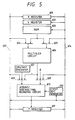
    • Fig. 5 is a block diagram of an apparatus for executing the arithmetic processing of Fig. 4.
    • Fig. 6 is a flow chart of arithmetic processing according to a third embodiment of this invention.
    • Fig. 7 is a block diagram of an apparatus for executing arithmetic processing in a sixth embodiment of this invention.
    • Fig. 8 is a block diagram of the multiplier circuit of Fig. 7.
    DESCRIPTION OF THE FIRST PREFERRED EMBODIMENT
  • With reference to Fig. 1, a first step 101 executes a process of calculating an approximate value. Specifically, the step 101 executes approximate calculation of a given function F(X) with respect to a given value X. An approximate solution of the function F(X) is calculated by a suitable way such as Newton's method. This calculation is realized by using multipliers and adders. In this calculation, the approximate solution is determined at an accuracy where the error between the approximate solution and the infinitely precise solution is smaller than the weight of the digit in a place which is lower than the lowest place of the required significant digits for a final result by two places. According to the double precision prescribed in IEEE754 standards, the number of significant digits of a mantissa part is 53, and the significant digit in the highest place has a weight of 20 and the significant digit in the lowest place has a weight of 2-52. In this case, the error between the mantissa part Ya of the approximate solution and the mantissa part Y of the infinitely precise solution satisfies the following relation. |Y - Ya| < 2 -54
    Figure imgb0005
       Fig. 2 shows an example of a number line. In Fig. 2, sets of three digits, "000" to "100", denote the value of the lowest place of significant digits and the following lower places, wherein digits have the weights of 2-52, 2-53, 2-54, respectively. The scale points are spaced at equal intervals of 2-54. It is now assumed that the infinitely precise value (the infinitely precise solution) Y lies at a point 201. Since the infinitely precise value Y has an infinite accuracy and an infinite number of digits, the point 201 of the infinitely precise value Y is on the infinitesimal scale. The approximate solution Ya has a number of digits which is determined by the calculation algorithm and the used hardware. In general, one or more of the digits of the approximate solution Ya are located in places lower than the place corresponding to the maximal error, that is, the place having a weight of 2-54. The place having a weight of 2-54 is sometimes shortened to "the place of 2-54" or "the 2-54 place" in the following description. Other places are similarly shortened. It is known from the equation (3) that the approximate solution Ya lies in a region 200 of 2-53 which is defined between points 202 and 203.
  • Returning to Fig. 1, a step 102 rounds the approximate value Ya given by the step 101, and thereby calculates an interim solution Yr from the approximate value Ya. The interim solution Yr agrees with one of possible interim solutions which is closest to the approximate solution Ya, and each of the possible interim solutions can be represented by digits whose number is larger than the number of the significant digits and whose places are higher than the place corresponding to the minimal weight greater than the maximal error of the approximate solution Ya. In other words, the interim solution Yr is equal to one of possible interim solutions which is closest to the approximate solution Ya and the possible interim solutions are represented by digits in places, the lowest of which is arbitrarily selected from a place range starting from a place lower than the lowest place of the significant digits for the final solution by at least one place and ending at a place higher than a place of a minimal weight by at least one place, and a weight of digit in the minimal-weight place is greater than a maximum of an error of the approximate solution Ya.
  • In this regard, a description will be given by reference to Fig. 2. For example, in the case of an interim solution Yr having 54 digits whose number is greater than the number of the significant digits by one, the interim solution Yr agrees with a point 204 or a point 205. Specifically, when the approximate solution Ya lies between a point 202 and a point 206, the interim solution Yr agrees with the point 204. When the approximate solution Ya lies between a point 203 and a point 206, the interim solution Yr agrees with the point 205. Therefore, the error between the infinitely precise value Y and the interim solution Yr satisfies the following relation. |Y - Yr| < 2 -53
    Figure imgb0006
    Thus, the interim solution Yr is represented by digits in places, the lowest of which is lower than the lowest place of the significant digits by one place.
  • As shown in Fig. 1, a step 103 following the step 102 calculates an inverse function value Xr from the interim solution Yr. The inverse function value Xr is given as " Xr=F -1 (Yr)
    Figure imgb0007
    ".
  • A step 104 following the step 103 compares the inverse function value Xr and the given value X. When the inverse function value Xr and the given value X are equal, the interim solution Yr equals the infinitely precise value Y. In this case, a step 106 is executed after the step 104. The step 106 sets a sticky digit S to 0. When the inverse function value Xr and the given value X are different, there is an error between the interim solution Yr and the infinitely precise value Y. In this case, a step 105 is executed after the step 104. The step 105 decides whether the error of the interim solution Yr lies at a higher side or a lower side of the infinitely precise value Y.
  • The step 105 will be described in detail. The step 105 decides which of the infinitely precise value Y and the interim solution Yr is larger on the basis of the relation between the magnitudes of the given value X and the inverse function value Xr, and also on the basis of the characteristics of the function F. In the case where the given function F agrees with a monotonically increasing function or a monotonically decreasing function, the decision by the step 105 can be easily executed by referring to the relation between the magnitudes of the given value X and the inverse function value Xr. For example, in the case where the given function F agrees with a monotonically increasing function, the infinitely precise value Y is greater and smaller than the interim solution Yr when the given value X is greater and smaller than the inverse function value Xr respectively. When the result of the decision by the step 105 represents that the infinitely precise value Y is smaller than the interim solution Yr, a step 107 is executed next. The step 107 sets the sticky digit S to -1. When the result of the decision by the step 105 represents that the infinitely precise value Y is greater than the interim solution Yr, a step 108 is executed next. The step 108 sets the sticky digit S to 1. In the example of Fig. 2, the sticky digit S is set to 1 and -1 when the interim solution Yr agrees with the point 204 and the point 205 respectively.
  • After the steps 106, 107, and 108, a final step 109 is executed. The step 109 adds the sticky digit S to a place immediately lower than the lowest place of the digits of the interim solution Yr, and thus performs the addition "Yr+2-54S". The step 109 rounds the result of the addition to the significant digits in a designated rounding mode and thereby derives a final calculation result Ye. The data which represent the result of the addition have digits whose number is larger than the number of the significant digits by 2. In Fig. 2, the data are denoted by the point 206. As understood from Fig. 2, the point 206 and the infinitely precise value 201 (the infinitely precise value Y) lie between points 204 and 207 which are different only in the lowest-place significant digit by 1, and the point 206 and the infinitely precise value 201 (the infinitely precise value Y) lie at a common side of the middle point 205 between the points 204 and 207. Thus, the result of rounding the point 206 to the significant digits is equal to the result of rounding the infinitely precise value 201 (the infinitely precise value Y) to the significant digits.
  • Fig. 3 shows an apparatus for executing the arithmetic processing of Fig. 1. As shown in Fig. 3, the apparatus includes selectors 501, 503, and 504, a function calculating device 502, an adding/subtracting rounding circuit 505, a register 506, and a sticky digit generator 507. In general, these devices 501-507 are controlled by a controller (not shown).
  • Data of a given value X are selected by the selector 501 and are transmitted to the function calculating device 502. The function calculating device 502 executes approximate calculation of a function F with respect to the given value X, thereby calculating an approximate solution Ya. In this way, the operation of the step 101 of Fig. 1 is executed by the function calculating device 502.
  • Data of the approximate solution Ya are outputted from the function calculating device 502 to the selector 503. The data of the approximate solution Ya are selected by the selector 503, and are transmitted to the adding/subtracting rounding circuit 505. At the same time, data of "0" are selected by the selector 504, and are transmitted to the adding/subtracting rounding circuit 505. The adding/subtracting rounding circuit 505 rounds the approximate solution Ya to an interim solution Yr. In this way, the operation of the step 102 of Fig. 1 is executed by the adding/subtracting rounding circuit 505. The adding/subtracting rounding circuit 505 outputs data of the interim solution Yr which are stored into the register 506.
  • The data of the interim solution Yr are selected by the selector 501, and are transmitted to the function calculating device 502. The function calculating device 502 calculates an inverse function value " Xr=F -1 (Yr)
    Figure imgb0008
    " with respect to the interim solution Yr. In this way, the operation of the step 103 of Fig. 1 is executed by the function calculating device 502.
  • The function calculating device 502 outputs data of the inverse function value Xr to the selector 503. The data of the inverse function value Xr are selected by the selector 503, and are transmitted to the adding/subtracting rounding circuit 505. At the same time, the data of the given value X are selected by the selector 504, and are transmitted to the adding/subtracting rounding circuit 505. The adding/subtracting rounding circuit 505 includes a subtracter which subtracts the given value X from the inverse function value Xr and thus which derives a difference equal to "Xr-X". Data of the difference "Xr-X" are outputted from the adding/subtracting rounding circuit 505 to the sticky digit generator 507. In the case where the difference "Xr-X" is 0, the sticky digit generator 507 outputs data representing a sticky digit S equal to 0. In the case where the difference "Xr-X" differs from 0, the sticky digit generator 507 executes a decision as to which of the infinitely precise solution Y and the interim solution Yr is greater on the basis of the characteristics of the function F and the information of the sign of the difference "Xr-X". When the infinitely precise solution Y is smaller than the interim solution Yr, the sticky digit generator 507 outputs data representing the sticky digit S equal to -1. When the infinitely precise solution Y is greater than the interim solution Yr, the sticky digit generator 507 outputs data representing the sticky digit S equal to 1. In this way, the operations of the steps 104-108 of Fig. 1 are executed by the adding/subtracting rounding circuit 505 and the sticky digit generator 507.
  • The data of the sticky digit S are fed from the sticky digit generator 507 to the adding/subtracting rounding circuit 505. At the same time, the data of the interim solution Yr which are outputted from the register 506 are selected by the selector 503, and are transmitted to the adding/subtracting rounding circuit 505. The adding/subtracting rounding circuit 505 includes an adder which adds the sticky digit S to the place immediately lower than the lowest place of the digits of the interim solution Yr. The adding/subtracting rounding circuit 505 rounds the result of this addition in a designated rounding mode to obtain a final solution Ye. In this way, the operation of the step 109 of Fig. 1 is executed by the adding/subtracting rounding circuit 505. Data (a digital signal) of the final solution Ye are transmitted from the adding/subtracting rounding circuit 505 to an external circuit (not shown) and are used therein.
  • DESCRIPTION OF THE SECOND PREFERRED EMBODIMENT
  • A second embodiment of this invention relates to division and uses IEEE754 standards. A description will be given of a normalized mantissa part. A mantissa part has 53 significant digits, and the significant digit in the highest place has a weight of 20 and the significant digit in the lowest place has a weight of 2-52. When both of a dividend X and a divisor Y are positive, the numbers X and Y satisfy the relation "1 ≦ X, Y<2".
  • With reference to Fig. 4, a first step 301 calculates an approximate quotient Za of division of X/Y in a suitable way such as Newton's method. The step 301 corresponds to the step 101 of Fig. 1. It is now assumed that the dividend X is not smaller than the divisor Y. In this case, the infinitely precise quotient Z which equals X/Y satisfies the relation "1 ≦ Z<2". The accuracy of the approximate quotient Za is defined by the error between the approximate quotient Za and the infinitely precise quotient Z. The error between the approximate quotient Za and the infinitely precise quotient Z is smaller than the weight of the digit in a place which is lower than the lowest place of the required significant digits for a final result by two places. According to the double precision prescribed in IEEE754 standards, since the digit in the lowest place has a weight of 2-52, the error between the approximate quotient Za and the infinitely precise quotient Z satisfies the following relation. |Z - Za| < 2 -54
    Figure imgb0009
       A step 302 following the step 301 executes rounding similar to the rounding executed by the step 102 of Fig. 1. Specifically, the step 302 rounds the approximate quotient Za given by the step 301, and thereby calculates an interim quotient Zr from the approximate quotient Za. The interim quotient Zr agrees with one of possible interim quotients which is closest to the approximate quotient Za, and each of the possible interim quotients can be represented by digits whose number is larger than the number of the significant digits and whose places are higher than the place corresponding to the minimal weight greater than the maximal error of the approximate quotient Za. In other words, the interim quotient Zr is equal to one of possible interim quotients which is closest to the approximate quotient Za and the possible interim quotients are represented by digits in places, the lowest of which is arbitrarily selected from a place range starting from a place lower than the lowest place of the significant digits for the final quotient by at least one place and ending at a place higher than a place of a minimal weight by at least one place, and a weight of digit in the minimal-weight place is greater than a maximum of an error of the approximate quotient Za. For example, in the case of an interim quotient Zr having 54 digits whose number is greater than the number of the significant digits by one, the error between the infinitely precise quotient Z and the interim quotient Zr satisfies the following relation. |Z - Zr| < 2 -53
    Figure imgb0010
    Thus, the interim quotient Zr is represented by digits in places, the lowest of which is lower than the lowest place of the significant digits by one place.
  • A step 303 following the step 302 corresponds to the step 103 of Fig. 1. Specifically, the step 303 calculates an inverse function value Xr with respect to the function " Z=X/Y
    Figure imgb0011
    " on the basis of the interim quotient Zr. The inverse function value Xr agrees with the product " Xr=Zr × Y
    Figure imgb0012
    ".
  • A step 304 following the step 303 corresponds to the steps 104 and 105 of Fig. 1. Specifically, the step 304 compares the product Xr and the given value X to decide whether the error of the interim quotient Zr lies at the lower side or the higher side of the infinitely precise quotient Z. Since both of the given values X and Y are positive and thus the infinitely precise quotient Z corresponds to a monotonically increasing function of the given value X in the division "X/Y", a sticky digit S can be determined only by the comparison between the given value X and the product Xr. When the given value X is smaller than the product Xr, that is, when the infinitely precise quotient Z is smaller than the interim quotient Zr, the step 304 is followed by a step 305 which sets the sticky digit S to -1. When the given value X and the product Xr are equal, that is, when the infinitely precise quotient Z and the interim quotient Zr are equal, the step 304 is followed by a step 306 which sets the sticky digit S to 0. When the given value X is greater than the product Xr, that is, when the infinitely precise quotient Z is greater than the interim quotient Zr, the step 304 is followed by a step 307 which sets the sticky digit S to 1.
  • After the steps 305, 306, and 307, a final step 308 is executed. The step 308 executes rounding similar to the rounding executed by the step 109 of Fig. 1. Specifically, the step 308 adds the sticky digit S to a place immediately lower than the lowest place of the digits of the interim quotient Zr, and thus performs the addition "Zr+2-54S". The step 308 rounds the result of the addition to the significant digits in a designated rounding mode and thereby derives a final calculation result Ze. The final result Ze is equal to the result of rounding the infinitely precise quotient Z.
  • A description will be given of the case where the dividend X is smaller than the divisor Y. The calculations and decisions executed in this case are similar to those executed in the case where the dividend X is not smaller than the divisor Y except for the following points. In the case where the dividend X is smaller than the divisor Y, the infinitely precise quotient Z which equals X/Y satisfies the relation "1/2<Z<1". In this case, the digit in the 20 place of the infinitely precise quotient Z is 0, and the lowest-place digit of the final quotient Ze is located at the 2-53 place which is lower by one place than that occurring in the case where the dividend X is not smaller than the divisor Y. Therefore, the error between the approximate quotient Za and the infinitely precise quotient Z satisfies the following relation. |Z - Za| < 2 -55
    Figure imgb0013
    The interim quotient Zr requires 55 digits or more in places equal to and above the 2-54 place. Accordingly, the interim quotient Zr is calculated so that the following relation can be satisfied. |Z - Zr| < 2 -54
    Figure imgb0014
    In addition, the step 308 rounds the result of the addition to the significant digits in the places equal to and above the 2-53 place.
  • This embodiment may be modified as follows. In the case where the dividend X is not smaller than the divisor Y, the interim quotient Zr may be calculated at an accuracy higher by one digit so that the equation (8) can be satisfied.
  • Fig. 5 shows an apparatus for executing the arithmetic processing of Fig. 4. As shown in Fig. 5, the apparatus includes an X register 601, a Y register 602, a T register 611, a ROM 603, selectors 604, 605, 608, and 609, a multiplier circuit 606, a constant generator 607, an adding/subtracting rounding circuit 610, a sticky digit generator 612, and data buses 613 and 614. In general, the devices 601-612 are controlled by a controller (not shown).
  • Data of a dividend X are stored into the X register 601 via the data bus 613. Data of a divisor Y are stored into the Y register 602 via the data bus 614. Then, approximate division for calculating an approximate quotient Za is started. In this approximate division, multiplication, addition, and subtraction are reiterated to derive the approximate quotient Za. By using Newton's method, the division " Z=X/Y
    Figure imgb0015
    " can be performed as follows. A first approximate value R0 of 1/Y is determined by referring to a table. Then, an approximate solution Rn of 1/Y is calculated by repeatedly using the previously-mentioned recurrence formula (1) "n" times. Finally, an approximate value of X/Y can be obtained by multiplying Rn and X.
  • The calculation of the approximate quotient Za is executed in the following sequence.
    • 1) The data of the divisor Y are fed from the Y register 602 to the ROM 603 via the data bus 614, and data of an approximate value R0 of 1/Y are outputted from the ROM 603 to the selectors 604 and 605.
    • 2) The data of the approximate value R0 are selected by the selector 604, and are transmitted to the multiplier circuit 606. At the same time, the data of the divisor Y are transmitted from the Y register 602 to the multiplier circuit 606 via the data bus 614 and the selector 605. The multiplier circuit 606 calculates the product "R0·Y". The multiplier circuit 606 outputs data of the product "R0·Y" to the selector 609.
    • 3) The selector 608 selects data of the value "2" which are generated by the constant generator 607, and the selected data are transmitted to the adding/subtracting rounding circuit 610. The data of the product "R0·Y" are selected by the selector 609, and are transmitted to the adding/subtracting rounding circuit 610. The adding/subtracting rounding circuit 610 includes a subtracter which subtracts the product "R0·Y" from the value "2" and thus which calculates the value "2-R0·Y". The adding/subtracting rounding circuit 610 rounds the calculated value "2-R0·Y". The adding/subtracting rounding circuit 610 outputs data of the rounded value "2-R0·Y" to the selector 604 via the data bus 613.
    • 4) The data of the rounded value "2-R0·Y" are selected by the selector 604, and are transmitted to the multiplier circuit 606. At the same time, the data of the approximate value R0 are selected by the selector 605, and are transmitted to the multiplier circuit 606. The multiplier circuit 606 calculates the product "R0(2-R0·Y)". The multiplier circuit 606 outputs data of the product "R0(2-R0·Y)" to the selector 608.
    • 5) The data of the product "R0(2-R0·Y)" are selected by the selector 608, and are transmitted to the adding/subtracting rounding circuit 610. At the same time, data of "0" are selected by the selector 609, and are transmitted to the adding/subtracting rounding circuit 610. The adding/subtracting rounding circuit 610 rounds the product "R0(2-R0·Y)" to a value R1. The adding/subtracting rounding circuit 610 outputs data of the value R1 which are stored into the T register 611.
    • 6) The value R1 is used in place of the value R0, and the previously-mentioned processings 2)-5) are executed to obtain a next value R2. Such operation is reiterated to derive an adequately-accurate value Rn.
    • 7) The adding/subtracting rounding circuit 610 outputs data of the value Rn which are transmitted to the multiplier circuit 606 via the data bus 613 and the selector 604. At the same time, the data of the dividend X are transmitted from the X register 601 to the multiplier circuit 606 via the data bus 614 and the selector 605. The multiplier circuit 606 calculates the product of the values Rn and X, that is, the approximate quotient " Za=R n ·X
      Figure imgb0016
      " for an infinitely precise quotient X/Y. The multiplier circuit 606 outputs data of the approximate quotient Za to the selector 608.
  • In this way, the operation of the step 301 of Fig. 5 is executed by the devices 601-611. After the approximate quotient Za is calculated, the apparatus of Fig. 5 operates as follows.
  • The data of the approximate quotient Za are selected by the selector 608, and are transmitted to the adding/subtracting rounding circuit 610. At the same time, the data of "0" are selected by the selector 609, and are transmitted to the adding/subtracting rounding circuit 610. The adding/subtracting rounding circuit 610 rounds the approximate quotient Za to an interim quotient Zr. The adding/subtracting rounding circuit 610 outputs data of the interim quotient Zr which are stored into the T register 611. In this way, the operation of the step 302 of Fig. 4 is executed by the adding/subtracting rounding circuit 610.
  • The data of the interim quotient Zr are transmitted to the multiplier circuit 606 via the data bus 613 and the selector 604. At the same time, the data of the divisor Y are transmitted to the multiplier circuit 606 via the data bus 614 and the selector 605. The multiplier circuit 606 calculates an inverse function value Xr with respect to the interim quotient Zr, that is, calculates the product " Xr=Zr·Y
    Figure imgb0017
    " of the values Zr and Y. The multiplier circuit 606 outputs data of the product Xr to the selector 608. In this way, the operation of the step 303 of Fig. 4 is executed by the multiplier circuit 606.
  • The data of the product Xr are selected by the selector 608, and are transmitted to the adding/subtracting rounding circuit 610. At the same time, the data of the dividend X are transmitted from the X register 601 to the adding/subtracting rounding circuit 610 via the data bus 614 and the selector 609. The adding/subtracting rounding circuit 610 includes a subtracter which subtracts the dividend X from the product Xr and thus which derives a difference equal to "Xr-X". Data of the difference "Xr-X" are outputted from the adding/subtracting rounding circuit 610 to the sticky digit generator 612. In the case where the difference "Xr-X" is 0, the sticky digit generator 612 outputs data representing a sticky digit S equal to 0. In the case where the difference "Xr-X" is negative, the sticky digit generator 612 outputs data representing the sticky digit S equal to 1. In the case where the difference "Xr-X" is positive, the sticky digit generator 612 outputs data representing the sticky digit S equal to -1. In this way, the operations of the steps 304-307 of Fig. 4 are executed by the adding/subtracting rounding circuit 610 and the sticky digit generator 612.
  • The data of the sticky digit S are fed from the sticky digit generator 612 to the adding/subtracting rounding circuit 610. At the same time, the data of the interim quotient Zr which are outputted from the T register 611 are selected by the selector 608, and are transmitted to the adding/subtracting rounding circuit 610. The adding/subtracting rounding circuit 610 includes an adder which adds the sticky digit S to the place immediately lower than the lowest place of the digits of the interim quotient Zr. The adding/subtracting rounding circuit 610 rounds the result of this addition in a designated rounding mode to obtain a final quotient Ze. In this way, the operation of the step 308 of Fig. 4 is executed by the adding/subtracting rounding circuit 610. Data (a digital signal) of the final quotient Ze are transmitted from the adding/subtracting rounding circuit 610 to an external circuit (not shown), and are used therein.
  • While the dividend X and the divisor Y are positive in the previously-mentioned description, division in other cases is executed similarly except for the following points. Specifically, in the case where the signs of the dividend X and the quotient Z are equal, the sticky digit S is set to 0 when the product Xr and the dividend X are equal and the sticky digit S is set to -1 and 1 when the value Xr is greater and smaller than the value X respectively. In the case where the signs of the dividend X and the quotient Z are different, the sticky digit S is set to 0 when the product Xr and the dividend X are equal and the sticky digit S is set to 1 and -1 when the value Xr is greater and smaller than the value X respectively.
  • DESCRIPTION OF THE THIRD PREFERRED EMBODIMENT
  • A third embodiment of this invention relates to calculation of a square root and uses IEEE754 standards. A description will be given of a normalized mantissa part. A mantissa part has 53 significant digits, and the significant digit in the highest place has a weight of 20 and the significant digit in the lowest place has a weight of 2-52. In the case of a floating point data whose exponent equals an even number, it is sufficient to consider a given value X in the range "1 ≦ X<2". In the case of a floating point data whose exponent equals an odd number, its mantissa part should be shifted leftward by one place and the square root of the resultant mantissa part should be calculated, and thus it is necessary to consider a given value X in the range "2 ≦ X<4". Accordingly, when similar processing is done independent of whether the exponent is even or odd, it is sufficient to consider a given value X "1 ≦ X<4". Thus, the square root Y of the given value X is in the range "1 ≦ Y<2".
  • With reference to Fig. 6, a first step 401 calculates an approximate square root Ya of a given value X in a suitable way such as Newton's method. The step 401 corresponds to the step 101 of Fig. 1. The accuracy of the approximate square root Ya is defined by the error between the approximate square root Ya and the infinitely precise square root Y ( Y=X 1/2
    Figure imgb0018
    ). The error between the approximate square root Ya and the infinitely precise square root Y is smaller than the weight of the digit in a place which is lower than the lowest place of the required significant digits for a final result by two places. According to the double precision prescribed in IEEE754 standards, since the significant digit in the lowest place has a weight of 2-52, the error between the approximate square root Ya and the infinitely precise square root Y satisfies the following relation. |Y - Ya| < 2 -54
    Figure imgb0019
       A step 402 following the step 401 executes rounding similar to the rounding executed by the step 102 of Fig. 1. Specifically, the step 402 rounds the approximate square root Ya given by the step 301, and thereby calculates an interim square root Yr from the approximate square root Ya. The interim square root Yr agrees with one of possible interim square roots which is closest to the approximate square root Ya, and each of the possible interim square roots can be represented by digits whose number is larger than the number of the significant digits and whose places are higher than the place corresponding to the minimal weight greater than the maximal error of the approximate square root Ya. In other words, the interim square root Yr is equal to one of possible interim square roots which is closest to the approximate square root Ya and the possible interim square roots are represented by digits in places, the lowest of which is arbitrarily selected from a place range starting from a place lower than the lowest place of the significant digits for the final square root by at least one place and ending at a place higher than a place of a minimal weight by at least one place, and a weight of digit in the minimal-weight place is greater than a maximum of an error of the approximate square root Ya. For example, in the case of an interim square root Yr having 54 digits whose number is greater than the number of the significant digits by one, the error between the infinitely precise square root Y and the interim square root Yr satisfies the following relation. |Y - Yr| < 2 -53
    Figure imgb0020
    Thus, the interim square root Yr is represented by digits in places, the lowest of which is lower than the lowest place of the significant digits by one place.
  • A step 403 following the step 402 corresponds to the step 103 of Fig. 1. Specifically, the step 403 executes multiplication and thereby calculates an inverse function value Xr with respect to the function " Y=X 1/2
    Figure imgb0021
    " on the basis of the interim square root Yr. The inverse function value Xr agrees with the square " Xr=Yr 2
    Figure imgb0022
    ".
  • A step 404 following the step 403 corresponds to the steps 104 and 105 of Fig. 1. Specifically, the step 404 compares the square Xr and the given value X to decide whether the error of the interim square root Yr lies at the lower side or the higher side of the infinitely precise square root Y. Since the infinitely precise square root Y corresponds to a monotonically increasing function of the given value X in the square root " Y=X 1/2
    Figure imgb0023
    ", a sticky digit S can be determined only by the comparison between the given value X and the square Xr. When the given value X is smaller than the square Xr, that is, when the infinitely precise square root Y is smaller than the interim square root Yr, the step 404 is followed by a step 405 which sets the sticky digit S to -1. When the given value X and the square Xr are equal, that is, when the infinitely precise square root Y and the interim square root Y are equal, the step 404 is followed by a step 406 which sets the sticky digit S to 0. When the given value X is greater than the square Xr, that is, when the infinitely precise square root Y is greater than the interim square root Yr, the step 404 is followed by a step 407 which sets the sticky digit S to 1.
  • After the steps 405, 406, and 407, a final step 408 is executed. The step 408 executes rounding similar to the rounding executed by the step 109 of Fig. 1. Specifically, the step 408 adds the sticky digit S to a place immediately lower than the lowest place of the digits of the interim square root Yr, and thus performs the addition "Yr+2-54S". The step 408 rounds the result of the addition to the significant digits in a designated rounding mode and thereby derives a final calculation result Ye. The final result Ye is equal to the result of rounding the infinitely precise square root Y.
  • An apparatus for executing the arithmetic processing of Fig. 6 is similar to the apparatus of Fig. 5. The apparatus operates as follows.
  • Data of a given value X are stored into the X register 601 via the data bus 613. Then, approximate square root calculation for calculating an approximate square root Ya is started. In this approximate square root calculation, multiplication, addition, and subtraction are reiterated to derive the approximate square root Ya as in the embodiment of Figs. 4 and 5. By using Newton's method, square root calculation " Y=X 1/2
    Figure imgb0024
    " can be performed as follows. A first approximate value R0 of 1/X1/2 is determined by referring to a table. Then, an approximate solution Rn of 1/X1/2 is calculated by repeatedly using the previously-mentioned formula (2) "n" times. Finally, an approximate value of X1/2 can be obtained by multiplying Rn and X. The multiplier circuit 606 outputs data of the approximate square root Ya to the selector 608.
  • The data of the approximate square root Ya are selected by the selector 608, and are transmitted to the adding/subtracting rounding circuit 610. At the same time, the data of "0" are selected. by the selector 609, and are transmitted to the adding/subtracting rounding circuit 610. The adding/subtracting rounding circuit 610 rounds the approximate square root Ya to an interim square root Yr. The adding/subtracting rounding circuit 610 outputs data of the interim square root Yr which are stored into the T register 611. In this way, the operation of the step 402 of Fig. 6 is executed by the adding/subtracting rounding circuit 610.
  • The data of the interim square root Yr are transmitted to the multiplier circuit 606 via both of the selectors 604 and 605. The multiplier circuit 606 calculates an inverse function value Xr with respect to the interim square root Yr, that is, calculates the square " Xr=Yr 2
    Figure imgb0025
    " of the interim square root Yr. The multiplier circuit 606 outputs data of the square Xr to the selector 608. In this way, the operation of the step 403 of Fig. 6 is executed by the multiplier circuit 606.
  • The data of the square Xr are selected by the selector 608, and are transmitted to the adding/subtracting rounding circuit 610. At the same time, the data of the given value X are transmitted from the X register 601 to the adding/subtracting rounding circuit 610 via the data bus 614 and the selector 609. The adding/subtracting rounding circuit 610 includes a subtracter which subtracts the given value X from the square Xr and thus which derives a difference equal to "Xr-X". Data of the difference "Xr-X" are outputted from the adding/subtracting rounding circuit 610 to the sticky digit generator 612. In the case where the difference "Xr-X" is 0, the sticky digit generator 612 outputs data representing a sticky digit S equal to 0. In the case where the difference "Xr-X" is negative, the sticky digit generator 612 outputs data representing the sticky digit S equal to 1. In the case where the difference "Xr-X" is positive, the sticky digit generator 612 outputs data representing the sticky digit S equal to -1. In this way, the operations of the steps 404-407 of Fig. 6 are executed by the adding/subtracting rounding circuit 610 and the sticky digit generator 612.
  • The data of the sticky digit S are fed from the sticky digit generator 612 to the adding/subtracting rounding circuit 610. At the same time, the data of the interim square root Yr which are outputted from the T register 611 are selected by the selector 608, and are transmitted to the adding/subtracting rounding circuit 610. The adding/subtracting rounding circuit 610 includes an adder which adds the sticky digit S to the place immediately lower than the lowest place of the digits of the interim square root Yr. The adding/subtracting rounding circuit 610 rounds the result of this addition in a designated rounding mode to obtain a final square root Ye. In this way, the operation of the step 408 of Fig. 4 is executed by the adding/subtracting rounding circuit 610. Data (a digital signal) of the final square root Ye are transmitted from the adding/subtracting rounding circuit 610 to an external circuit (not shown), and are used therein.
  • DESCRIPTION OF THE FOURTH PREFERRED EMBODIMENT
  • A fourth embodiment of this invention is similar to the embodiment of Figs. 4 and 5 except for a design indicated hereinafter. The fourth embodiment relates to division and uses IEEE754 standards. A description will be given of a normalized mantissa part. A mantissa part has 53 significant digits, and the significant digit in the highest place has a weight of 20 and the significant digit in the lowest place has a weight of 2-52. When both of a dividend X and a divisor Y are positive, the numbers X and Y satisfy the relation "1 ≦ X, Y<2".
  • As in the embodiment of Figs. 4 and 5, an approximate quotient Za of division of X/Y is calculated, and then an interim quotient Zr is calculated by rounding the approximate quotient Za. The error δ between the interim quotient Zr and the infinitely precise quotient Z is given by the following equation. δ = Zr - Z
    Figure imgb0026
       An inverse function value Xr with respect to the function " Z=X/Y
    Figure imgb0027
    " is calculated on the basis of the interim quotient Zr. The inverse function value Xr agrees with the product " Xr=Zr × Y
    Figure imgb0028
    " which is expressed by the following equation. Xr = Zr × Y = (Z + δ) × Y = X + δ·Y = X + Δ
    Figure imgb0029
    where Δ denotes δ·Y. It is known from the equation (12) that the product Xr is greater than the given value X by the value Δ or δ·Y. When the absolute value of the error δ of the interim quotient Zr is smaller than 2-54, the maximum of the absolute value of the value Δ or δ·Y satisfies the following condition. |Δ|max = |δ·Y|max < 2 -54 ·2 < 2 -53
    Figure imgb0030
    The relation (13) reveals that the digits in places equal to and above the place having a weight of 2-53 are always 0 when the absolute value of the value Δ is represented by a binary number. Since a normalized mantissa part is now assumed, the digits of the dividend X in places equal to and below the place having a weight of 2-53 are always 0.
  • Therefore, in the case where the value Δ is positive, the digits of the product Xr in the 20 place to the 2-52 place are equal to the digits of the dividend X respectively, and the digit of the product Xr in the 2-53 place is 0 and the digits of the product Xr in the lower places are equal to the digits of the value Δ respectively. In the case where the value Δ is 0, the digits of the product Xr in the 20 place to the 2-52 place are equal to the digits of the dividend X respectively, and the digits of the product Xr in the lower places are 0. In the case where the value Δ is negative, the digits of the product Xr are equal to the dividend X minus the absolute value of the value Δ. Accordingly, in the case where the value Δ is negative, the digits of the product Xr in the 20 place to the 2-52 place are equal to the digits of the value which is smaller than the dividend X by 2-52 respectively, and the digit of the product Xr in the 2-53 place is 1 and the digits of the product Xr in the lower places are equal to the digits of the complement of the value Δ with respect to 2 respectively. As understood from the above description, it is possible to decide whether the value Δ is positive, negative, or 0 by examining the digits of the product Xr in the places equal to and below the place having a weight of 2-53.
  • Therefore, it is possible to decide which of the interim quotient Zr and the infinitely precise quotient Z is greater by referring to the relations (11) and (12). The sticky digit S can be determined on the basis of the result of this decision. Specifically, in the case where the digit of the product Xr in the 2-53 place is 0 and at least one of the digits of the product Xr in the 2-54 place and the lower places is different from 0, the value Δ is positive and the interim quotient Zr is greater than the infinitely precise quotient Z, and thus it is good to set the sticky digit S to -1. In the case where all the digits of the product Xr in the 2-53 place and the lower places are 0, the value Δ is 0 and the interim quotient Zr is equal to the infinitely precise quotient Z, and thus it is good to set the sticky digit S to 0. In the case where the digit of the product Xr in the 2-53 place is 1, the value Δ is negative and the interim quotient Zr is smaller than the infinitely precise quotient Z, and thus it is good to set the sticky digit S to 1.
  • As described previously, the decision as to which of the interim quotient Zr and the infinitely precise quotient Z is greater can be easily done by examining the digits of the product Xr in the 2-53 place and the lower places without performing the subtraction between the product Xr and the dividend X. In addition, the sticky digit S can be determined on the basis of the result of this decision.
  • This simple way of determining the sticky digit S can be used in calculations other than division by performing the following settings. An approximate solution Ya of the function " Y=F(X)
    Figure imgb0031
    ", and an interim solution Yr calculated by rounding the approximate solution Ya are determined so that the maximum of the absolute value of the difference between the given value X and the inverse function value " Xr=F -1 (Yr)
    Figure imgb0032
    " will be smaller than the weight of the place lower than the lowest place of the significant digits of the given value X by one place.
  • DESCRIPTION OF THE FIFTH PREFERRED EMBODIMENT
  • A fifth embodiment of this invention is similar to the embodiment of Fig. 6 except for a design indicated hereinafter. A consideration will be given of the case where the maximum of the absolute value of the difference between a given value X and an inverse function value " Xr=F -1 (Yr)
    Figure imgb0033
    " calculated from an interim solution Yr is greater than the weight of the place lower than the lowest place of the significant digits of the given value X by one place.
  • As in the embodiment of Fig. 6, an approximate square root Ya is calculated, and an interim square root Yr is calculated by rounding the approximate square root Ya. The error δ between the interim square root Yr and the infinitely precise square root Y is given by the following equation. δ = Yr - Y
    Figure imgb0034
       An inverse function value Xr with respect to the function " Y=X 1/2
    Figure imgb0035
    ", that is, the square " Xr=Yr 2
    Figure imgb0036
    ", is calculated on the basis of the interim square root Yr. The inverse function Xr is expressed by the following equation. Xr = Yr 2 = (Y + δ) 2 = X + 2δ·Y + δ 2 = X + Δ
    Figure imgb0037
    where Δ denotes 2δ·Y + δ2. It is known from the equation (15) that the square Xr is greater than the given value X by the value Δ or 2δ·Y + δ2. When the absolute value of the error δ of the interim square root Yr is smaller than 2-53, the maximum of the absolute value of the value Δ or 2δ·Y + δ2 satisfies the following condition. |Δ|max = |2δ·Y + δ 2 |max < 2·2 -53 ·2 + 2 -106 < 2 -51 + 2 -106
    Figure imgb0038
    The relation (16) reveals that the digits in places equal to and above the place having a weight of 2-50 are always 0 when the absolute value of the value Δ is represented by a binary number. Since a normalized mantissa part is now assumed, the digits of the given value X in places equal to and below the place having a weight of 2-53 are always 0. Thus, the non-0 digits of the given value X and the value Δ overlap at the places having weights of 2-51 and 2-52. Therefore, to decide which of the given value X and the square Xr is greater, it is necessary to examine not only the digits in the 2-53 place and the lower places but also the digits in the higher places.
  • In the case where the value Δ is calculated by subtracting the given value X from the square Xr, since the absolute value of the value Δ is smaller than 2-50 as understood from the relation (16), the examination of the digits of the subtraction result Δ in the 2-50 place and the lower places enables the decision as to which of the given value X and the square Xr is greater. The result of this decision in turn enables the decision as to which of the interim square root Yr and the infinitely precise square root Y is greater, and then a sticky digit S is determined.
  • Specifically, in the case where the digit of the value Δ in the 2-50 place is 0 and at least one of the digits of the value Δ in the 2-51 place and the lower places is different from 0, the value Δ is positive and the interim square root Yr is greater than the infinitely precise square root Y, and thus it is good to set the sticky digit S to -1. In the case where all the digits of the value Δ in the 2-50 place and the lower places are 0, the value Δ is 0 and the interim square root Yr is equal to the infinitely precise square root Y, and thus it is good to set the sticky digit S to 0. In the case where the digit of the value Δ in the 2-50 place is 1, the value Δ is negative and the interim square root Yr is smaller than the infinitely precise square root Y, and thus it is good to set the sticky digit S to 1.
  • More accurate square root calculation makes it possible to perform the decision as to which of the given value X and the square Xr is greater by examining only the digits of the square Xr in the 2-53 place and the lower places. Specifically, in the case where the absolute value of the error δ of the interim square root Yr is smaller than 2-56 the relation (16) is replaced by the following relation. |Δ|max = |2δ·Y + δ 2 |max < 2·2 -56 2 + 2 -112 < 2 -54 + 2 -112
    Figure imgb0039
    The relation (17) reveals that the digits in places equal to and above the place having a weight of 2-53 are always 0 when the absolute value of the value Δ is represented by a binary number. Accordingly, the sticky digit S can be easily determined as in the fourth embodiment.
  • DESCRIPTION OF THE SIXTH PREFERRED EMBODIMENT
  • A sixth embodiment of this invention is similar to the embodiments of Figs. 4-6 except for a design change indicated later. Fig. 7 shows an apparatus for executing arithmetic processing in the sixth embodiment. The apparatus of Fig. 7 differs from the apparatus of Fig. 5 as follows. A multiplier circuit 806 is used in place of the multiplier circuit 606. The multiplier circuit 806 receives the output data from the X register 601. A sticky digit generator 812 is used in place of the sticky digit generator 612. The sticky digit generator 812 generates data of a sticky digit S in response to the output data from the multiplier circuit 806. The data of the sticky digit S are fed from the sticky digit generator 812 to the adding/subtracting rounding circuit 610.
  • Fig. 8 shows an internal design of the multiplier circuit 806. In Fig. 8, data of a multiplicand, data of a multiplier, and data of a subtrahend are inputted into and held by a multiplicand input latch 701, a multiplier input latch 702, and a subtrahend input latch 703 respectively. The data of the multiplier are fed from the multiplier input latch 702 to a multiplier recoding circuit 704. The multiplier recoding circuit 704 serves to reduce the number of partial products. When the multiplier recoding circuit 704 uses 2-bit Booth's method for example, the number of partial products can be reduced to a number which approximately equals a half of the number of the digits of the fed multiplier. In 2-bit Booth's method, 2-bit segments of an input binary number are successively converted into one of the values "2", "1", "0", "-1", and "-2". The multiplier recoding circuit 704 outputs data of a recoded multiplier to partial product generation circuits 705. The data of the multiplicand are fed from the multiplicand input latch 701 to the partial product generation circuits 705. The partial product generation circuits 705 generate a plurality of partial products from the recoded multiplier and the multiplicand.
  • The data of the subtrahend are fed from the subtrahend input latch 703 to a subtrahend conversion circuit 706. The subtrahend conversion circuit 706 generates the sign inversion value of the subtrahend which is expressed in the same format as the format of the partial products of the multiplicand and the multiplier. In the case of a multiplier circuit handling binary numbers in internal calculation, this expression format is based on the complement of the subtrahend with respect to 2. In the case of a multiplier circuit handling redundant binary numbers in internal calculation, this expression format is based on a redundant binary number. The partial products and the sign inversion value of the subtrahend are added by partial product adder circuits 707 in a sequential manner or a tree manner, and the result of this addition is outputted to a multiplication result output latch 708.
  • As understood from the above description, the multiplier circuit of Fig. 8 can obtain the result of the subtraction of the subtrahend from the product of the multiplicand and the multiplier. The multiplier circuit of Fig. 8 is used as follows. Data of an interim square root Yr are inputted into both of the multiplicand input latch 701 and the multiplier input latch 702. Data of a given value X are inputted into the subtrahend input latch 703. In this case, the data stored in the multiplication result output latch 708 represent a value Δ expressed by the following equation. Δ = Yr 2 - X = Xr - X
    Figure imgb0040
    The multiplier circuit of Fig. 8 can calculate the value Δ at a high speed.
  • A sticky digit S in square root calculation can be determined by referring to the value Δ as in the fifth embodiment. Accurate calculation of the digits of the value Δ in the 2-50 place and the lower places is sufficient for the determination of the sticky digit S. In addition, calculation of an inverse function is used only in the generation of the sticky digit S. Therefore, the subtrahend input latch 703 and the subtrahend conversion circuit 706 do not require the number of places corresponding to the number of all the digits of the given value X but require only three places which correspond to the two places where the data of the absolute value of the value Δ and the data of the given value X overlap, and the immediately higher place. Specifically, the three required places correspond to the places having weights of 2-50, 2-51, and 2-52.
  • In addition, the multiplier circuit of Fig. 8 can be used for division. During the division, the decision as to which of the product Xr and the dividend X is greater can be performed by the multiplier circuit of Fig. 8 while the execution of the subtraction is omitted from the adding/subtracting rounding circuit 610. In response to the result of this decision, the sticky digit generator 812 determines the sticky digit S. The omission of the execution of the subtraction from the adding/subtracting rounding circuit 610 enables a higher operation speed.

Claims (4)

  1. An apparatus comprising:
       means for generating a plurality of partial products from a given multiplicand X and a given multiplier Y;
       means for generating a sign inversion value from at least a lower part of a subtrahend Z to enable place matching, the sign inversion value being expressed in a format the same as a form of expression of the partial products;
       means for adding the partial products and the sign inversion value; and
       means for detecting which of the subtrahend Z and the product of the given multiplicand X and the given multiplier Y is greater in response to a result of said adding by the adding means.
  2. A central processing unit including an arithmetic processing unit comprising an apparatus according to claim 1.
  3. A method comprising the steps of:
       generating a plurality of partial products from a given multiplicand and a given multiplier;
       generating a sign inversion value from at least a lower part of a subtrahend to enable place matching, the sign inversion value being expressed in a format the same as a format of expression of the partial products;
       adding the partial products and the sign inversion value; and
       detecting which of the subtrahend Z and the product of the given multiplicand X and the given multiplier Y is greater in response to a result of the addition.
  4. A central processing unit for carrying out arithmetic processing according to the method of claim 3.
EP96103447A 1989-10-16 1990-10-16 Arithmetic processing apparatus and method used thereby Withdrawn EP0723218A3 (en)

Applications Claiming Priority (3)

Application Number Priority Date Filing Date Title
JP268447/89 1989-10-16
JP26844789 1989-10-16
EP90311315A EP0424086B1 (en) 1989-10-16 1990-10-16 Arithmetic processing apparatus and method used thereby

Related Parent Applications (2)

Application Number Title Priority Date Filing Date
EP90311315.7 Division 1990-10-16
EP90311315A Division EP0424086B1 (en) 1989-10-16 1990-10-16 Arithmetic processing apparatus and method used thereby

Publications (2)

Publication Number Publication Date
EP0723218A2 true EP0723218A2 (en) 1996-07-24
EP0723218A3 EP0723218A3 (en) 1996-07-31

Family

ID=17458636

Family Applications (2)

Application Number Title Priority Date Filing Date
EP90311315A Expired - Lifetime EP0424086B1 (en) 1989-10-16 1990-10-16 Arithmetic processing apparatus and method used thereby
EP96103447A Withdrawn EP0723218A3 (en) 1989-10-16 1990-10-16 Arithmetic processing apparatus and method used thereby

Family Applications Before (1)

Application Number Title Priority Date Filing Date
EP90311315A Expired - Lifetime EP0424086B1 (en) 1989-10-16 1990-10-16 Arithmetic processing apparatus and method used thereby

Country Status (5)

Country Link
US (4) US5212661A (en)
EP (2) EP0424086B1 (en)
JP (1) JP2938547B2 (en)
KR (1) KR940010806B1 (en)
DE (1) DE69030707T2 (en)

Families Citing this family (32)

* Cited by examiner, † Cited by third party
Publication number Priority date Publication date Assignee Title
JP2783710B2 (en) * 1991-10-25 1998-08-06 沖電気工業株式会社 Orthogonal transformer
EP0546977A3 (en) * 1991-12-13 1994-10-19 Ibm Method and apparatus for solving numerical problems that use a plurality of processing elements operating in parallel
EP0578950A3 (en) * 1992-07-15 1995-11-22 Ibm Method and apparatus for converting floating-point pixel values to byte pixel values by table lookup
GB9312745D0 (en) * 1993-06-21 1993-08-04 Questech Ltd Accurate digital divider
US5612909A (en) * 1994-09-29 1997-03-18 Intel Corporation Method and apparatus for rounding operands using previous rounding history
US5563818A (en) * 1994-12-12 1996-10-08 International Business Machines Corporation Method and system for performing floating-point division using selected approximation values
US5729481A (en) * 1995-03-31 1998-03-17 International Business Machines Corporation Method and system of rounding for quadratically converging division or square root
US5742537A (en) * 1995-06-30 1998-04-21 Wolrich; Gilbert M. Fast determination of floating point sticky bit from input operands
US5726927A (en) * 1995-09-11 1998-03-10 Digital Equipment Corporation Multiply pipe round adder
US5729485A (en) * 1995-09-11 1998-03-17 Digital Equipment Corporation Fast determination of carry inputs from lower order product for radix-8 odd/even multiplier array
US5764555A (en) * 1996-03-13 1998-06-09 International Business Machines Corporation Method and system of rounding for division or square root: eliminating remainder calculation
EP0837390A1 (en) * 1996-10-18 1998-04-22 Texas Instruments Incorporated Improvements in or relating to microprocessor integrated circuits
US6115733A (en) * 1997-10-23 2000-09-05 Advanced Micro Devices, Inc. Method and apparatus for calculating reciprocals and reciprocal square roots
US6144980A (en) * 1998-01-28 2000-11-07 Advanced Micro Devices, Inc. Method and apparatus for performing multiple types of multiplication including signed and unsigned multiplication
US6115732A (en) * 1998-05-08 2000-09-05 Advanced Micro Devices, Inc. Method and apparatus for compressing intermediate products
US6134574A (en) * 1998-05-08 2000-10-17 Advanced Micro Devices, Inc. Method and apparatus for achieving higher frequencies of exactly rounded results
US6223198B1 (en) 1998-08-14 2001-04-24 Advanced Micro Devices, Inc. Method and apparatus for multi-function arithmetic
US6269384B1 (en) 1998-03-27 2001-07-31 Advanced Micro Devices, Inc. Method and apparatus for rounding and normalizing results within a multiplier
US6289365B1 (en) * 1997-12-09 2001-09-11 Sun Microsystems, Inc. System and method for floating-point computation
US6393554B1 (en) 1998-01-28 2002-05-21 Advanced Micro Devices, Inc. Method and apparatus for performing vector and scalar multiplication and calculating rounded products
US6487575B1 (en) * 1998-08-31 2002-11-26 Advanced Micro Devices, Inc. Early completion of iterative division
US6341300B1 (en) 1999-01-29 2002-01-22 Sun Microsystems, Inc. Parallel fixed point square root and reciprocal square root computation unit in a processor
US6384748B1 (en) 1998-12-21 2002-05-07 Base One International Corporation Method of encoding numeric data and manipulating the same
US6351760B1 (en) 1999-01-29 2002-02-26 Sun Microsystems, Inc. Division unit in a processor using a piece-wise quadratic approximation technique
JP2000260137A (en) * 1999-03-11 2000-09-22 Fujitsu Ltd Storage device
JP3708423B2 (en) * 2000-10-20 2005-10-19 株式会社日鉱マテリアルズ Phenolic curing agent for epoxy resin and epoxy resin composition using the same
US7031996B2 (en) * 2000-11-02 2006-04-18 Seagate Technology Llc Calculating square root of binary numbers with fixed-point microprocessor
US8015228B2 (en) * 2005-02-16 2011-09-06 Arm Limited Data processing apparatus and method for performing a reciprocal operation on an input value to produce a result value
JP4915454B2 (en) * 2010-02-24 2012-04-11 Nttエレクトロニクス株式会社 Arithmetic circuit and method
US9678714B2 (en) * 2014-07-11 2017-06-13 Imagination Technologies Limited Check procedure for floating point operations
US11416218B1 (en) 2020-07-10 2022-08-16 Ali Tasdighi Far Digital approximate squarer for machine learning
US11467805B1 (en) 2020-07-10 2022-10-11 Ali Tasdighi Far Digital approximate multipliers for machine learning and artificial intelligence applications

Citations (3)

* Cited by examiner, † Cited by third party
Publication number Priority date Publication date Assignee Title
US3202805A (en) * 1961-10-02 1965-08-24 Bunker Ramo Simultaneous digital multiply-add, multiply-subtract circuit
US4758972A (en) * 1986-06-02 1988-07-19 Raytheon Company Precision rounding in a floating point arithmetic unit
EP0326415A2 (en) * 1988-01-29 1989-08-02 Texas Instruments Incorporated Floating point/integer processor with divide and square root functions

Family Cites Families (10)

* Cited by examiner, † Cited by third party
Publication number Priority date Publication date Assignee Title
DE3267489D1 (en) * 1982-02-18 1986-01-02 Itt Ind Gmbh Deutsche Digital parallel calculating circuit for positive and negative binary numbers
JPS61256436A (en) * 1985-05-10 1986-11-14 Hitachi Ltd Arithmetic unit
US4817048A (en) * 1986-08-11 1989-03-28 Amdahl Corporation Divider with quotient digit prediction
JPS6347874A (en) * 1986-08-16 1988-02-29 Nec Corp Arithmetic unit
US4785412A (en) * 1987-07-20 1988-11-15 Control Data Corporation Double precision approximate quotient network
US4928259A (en) * 1988-09-23 1990-05-22 Intel Corporation Sticky bit predictor for floating-point multiplication
US5293558A (en) * 1988-11-04 1994-03-08 Hitachi, Ltd Multiplication, division and square root extraction apparatus
US4969118A (en) * 1989-01-13 1990-11-06 International Business Machines Corporation Floating point unit for calculating A=XY+Z having simultaneous multiply and add
US4941120A (en) * 1989-04-17 1990-07-10 International Business Machines Corporation Floating point normalization and rounding prediction circuit
USH1222H (en) * 1991-12-30 1993-08-03 Apparatus for determining sticky bit value in arithmetic operations

Patent Citations (3)

* Cited by examiner, † Cited by third party
Publication number Priority date Publication date Assignee Title
US3202805A (en) * 1961-10-02 1965-08-24 Bunker Ramo Simultaneous digital multiply-add, multiply-subtract circuit
US4758972A (en) * 1986-06-02 1988-07-19 Raytheon Company Precision rounding in a floating point arithmetic unit
EP0326415A2 (en) * 1988-01-29 1989-08-02 Texas Instruments Incorporated Floating point/integer processor with divide and square root functions

Non-Patent Citations (1)

* Cited by examiner, † Cited by third party
Title
ELECTRONIC ENGINEERING, vol. 52, no. 646, December 1980, LONDON GB, pages 21-23, XP002003039 GORNI: "16 by 8 bit divider etc." *

Also Published As

Publication number Publication date
US5434809A (en) 1995-07-18
EP0424086A2 (en) 1991-04-24
EP0424086B1 (en) 1997-05-14
US5633818A (en) 1997-05-27
JP2938547B2 (en) 1999-08-23
KR910008561A (en) 1991-05-31
US5313415A (en) 1994-05-17
DE69030707D1 (en) 1997-06-19
EP0723218A3 (en) 1996-07-31
US5212661A (en) 1993-05-18
EP0424086A3 (en) 1992-09-09
JPH03206557A (en) 1991-09-09
DE69030707T2 (en) 1997-10-02
KR940010806B1 (en) 1994-11-16

Similar Documents

Publication Publication Date Title
US5633818A (en) Method and apparatus for performing floating point arithmetic operation and rounding the result thereof
US5065352A (en) Divide apparatus employing multiplier with overlapped partial quotients
EP0149248B1 (en) Method and apparatus for division using interpolation approximation
EP0472139A2 (en) A floating-point processor
EP0351242B1 (en) Floating point arithmetic units
EP0356153B1 (en) Radix-2**n divider method and apparatus using overlapped quotient bit selection and concurrent quotient rounding and correction
US20070156803A1 (en) Overflow detection and clamping with parallel operand processing for fixed-point multipliers
US5260889A (en) Computation of sticky-bit in parallel with partial products in a floating point multiplier unit
US4896286A (en) Floating-point arithmetic apparatus
JP2003084969A (en) Floating point remainder computing element, information processing device, and computer program
US6317772B1 (en) Split remainder divider
KR940008611B1 (en) Binary floating point arithmetic rounding in conformance with ieee 754-1985 standard
US20220405054A1 (en) Process for Dual Mode Floating Point Multiplier-Accumulator with High Precision Mode for Near Zero Accumulation Results
US20220405051A1 (en) Power Saving Floating Point Multiplier-Accumulator with Precision-Aware Accumulation
JP3064405B2 (en) Complex number processing
US20220405052A1 (en) Process for Performing Floating Point Multiply-Accumulate Operations with Precision Based on Exponent Differences for Saving Power
JPH086766A (en) Sine and cosine arithmetic device
US20220405053A1 (en) Power Saving Floating Point Multiplier-Accumulator With a High Precision Accumulation Detection Mode
JP2518532B2 (en) Subtractor shift type divider
JP3233432B2 (en) Multiplier
WO2022271608A1 (en) Power saving floating point multiplier-accumulator with precision-aware accumulation
KR940008610B1 (en) Method and processor for high-speed convergence factor determination
JP2699658B2 (en) Square root arithmetic unit
JPH0414173A (en) Fixed point product sum computing element
JPH05100826A (en) Reciprocal arithmetic unit

Legal Events

Date Code Title Description
PUAI Public reference made under article 153(3) epc to a published international application that has entered the european phase

Free format text: ORIGINAL CODE: 0009012

PUAL Search report despatched

Free format text: ORIGINAL CODE: 0009013

17P Request for examination filed

Effective date: 19960306

AC Divisional application: reference to earlier application

Ref document number: 424086

Country of ref document: EP

AK Designated contracting states

Kind code of ref document: A2

Designated state(s): DE FR GB

AK Designated contracting states

Kind code of ref document: A3

Designated state(s): DE FR GB

17Q First examination report despatched

Effective date: 19980417

STAA Information on the status of an ep patent application or granted ep patent

Free format text: STATUS: THE APPLICATION IS DEEMED TO BE WITHDRAWN

18D Application deemed to be withdrawn

Effective date: 19990422