EP0724226A2 - IC card reader/writer - Google Patents
IC card reader/writer Download PDFInfo
- Publication number
- EP0724226A2 EP0724226A2 EP96100706A EP96100706A EP0724226A2 EP 0724226 A2 EP0724226 A2 EP 0724226A2 EP 96100706 A EP96100706 A EP 96100706A EP 96100706 A EP96100706 A EP 96100706A EP 0724226 A2 EP0724226 A2 EP 0724226A2
- Authority
- EP
- European Patent Office
- Prior art keywords
- card
- plate
- writer
- members
- section
- Prior art date
- Legal status (The legal status is an assumption and is not a legal conclusion. Google has not performed a legal analysis and makes no representation as to the accuracy of the status listed.)
- Granted
Links
Images


Classifications
-
- G—PHYSICS
- G06—COMPUTING; CALCULATING OR COUNTING
- G06K—GRAPHICAL DATA READING; PRESENTATION OF DATA; RECORD CARRIERS; HANDLING RECORD CARRIERS
- G06K7/00—Methods or arrangements for sensing record carriers, e.g. for reading patterns
- G06K7/0013—Methods or arrangements for sensing record carriers, e.g. for reading patterns by galvanic contacts, e.g. card connectors for ISO-7816 compliant smart cards or memory cards, e.g. SD card readers
- G06K7/0021—Methods or arrangements for sensing record carriers, e.g. for reading patterns by galvanic contacts, e.g. card connectors for ISO-7816 compliant smart cards or memory cards, e.g. SD card readers for reading/sensing record carriers having surface contacts
-
- G—PHYSICS
- G06—COMPUTING; CALCULATING OR COUNTING
- G06K—GRAPHICAL DATA READING; PRESENTATION OF DATA; RECORD CARRIERS; HANDLING RECORD CARRIERS
- G06K19/00—Record carriers for use with machines and with at least a part designed to carry digital markings
- G06K19/06—Record carriers for use with machines and with at least a part designed to carry digital markings characterised by the kind of the digital marking, e.g. shape, nature, code
- G06K19/067—Record carriers with conductive marks, printed circuits or semiconductor circuit elements, e.g. credit or identity cards also with resonating or responding marks without active components
- G06K19/07—Record carriers with conductive marks, printed circuits or semiconductor circuit elements, e.g. credit or identity cards also with resonating or responding marks without active components with integrated circuit chips
- G06K19/077—Constructional details, e.g. mounting of circuits in the carrier
- G06K19/07737—Constructional details, e.g. mounting of circuits in the carrier the record carrier consisting of two or more mechanically separable parts
- G06K19/07741—Constructional details, e.g. mounting of circuits in the carrier the record carrier consisting of two or more mechanically separable parts comprising a first part operating as a regular record carrier and a second attachable part that changes the functional appearance of said record carrier, e.g. a contact-based smart card with an adapter part which, when attached to the contact card makes the contact card function as a non-contact card
Definitions
- the present invention relates to an IC card reader/writer which can read information from or write information to, a thin-film type IC card for example.
- a processing apparatus for reading information from, or writing information to, a thin-type IC card is placed as an external apparatus and used to be connected by a connector cable, etc., to an interface, such as RS-232C, of a computer apparatus.
- the conventional processing device is of a box-like structure with an IC card set therein. This structure not only can protect internal component parts but also can protect and position the card.
- a contact holder holds contact pins in the box-like structure and is adapted to be moved up and down to allow the contact pins to be moved toward and away from an IC card inserted in the box-like structure.
- the IC card reader/writer cannot be made thinner and be inserted into a slot in a standardized card type device in a hand-held computer.
- an IC card reader/writer comprising first and second members arranged in a spaced-apart relation through supporting means provided between one-end sides thereof to define an IC card storage space between opposed surfaces thereof and, upon insertion of the IC card into the IC card storage space, providing an external shape substantially equal to that of a standard card, the reader/writer being insertable into, and withdrawable out of, a standard card holding section of an associated information processing apparatus via a one-end side.
- the IC card can be used for an information processing apparatus, such as a hand-held personal computer, which has been used for standard cards.
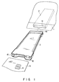
- FIG. 1 is a perspective view showing a computer 1, such as a notebook type personal computer as an information processing apparatus, an IC card reader/writer 3 and an IC card 5.
- a computer 1 such as a notebook type personal computer as an information processing apparatus, an IC card reader/writer 3 and an IC card 5.
- the computer apparatus 1 has an insertion inlet 1a at its front side to allow a card-type device to be inserted and a card holding section 2 provided for accommodating various kinds of cards, for example, a PC card (PCMCIA standard card) such as a memory card.
- the card holding section 2 is so dimensioned as to have a shape substantially satisfying the card standard.
- An associated connection area connected to the PC card is provided in the card holding section 2.
- the IC card reader/writer 3 is inserted via the insertion inlet 1a into the card holding section 2 of the computer apparatus 1 and has an LED 12 and eject button 13 on a side opposite to the insertion inlet 1a side.
- the IC card 5 has an IC (integrated circuit) terminal 6 and is inserted into the IC card reader/writer 3 and held there.
- FIG. 2 is a top view showing the IC card reader/writer 3.
- reference numeral 4 shows a main unit as a first member.
- the main unit 4 includes a contact block 7 comprised of eight pins making contact with the IC terminal 6 of the IC card 5, an ejecting mechanism, not shown, for ejecting the IC card 5, and so on.
- the main unit 4 has a connector section 10 at one end which serves as a first support section.
- FIG. 3 is a front view showing the IC card reader/writer 3.
- reference numeral 8 shows a base frame formed of metal or a molding and serving as a second member.
- the base frame 8 principally protects the undersurface of the IC card 5 and enables the terminal 6 of the IC card 5 to be placed in positive contact with the contact block 7.
- the base frame 8 and main unit 4 are spaced over 0.76 mm away from each other and, between their opposed surfaces, define a storage space 11 for holding the IC card therein.
- FIG. 4 is a cross-sectional view, taken along line IV-IV in FIG. 2.
- the IC card 5 is inserted into the storage space 11 between the base frame 8 and the main unit 4 and held therein.
- FIG. 5 is a bottom view showing the IC card reader/writer.
- the main unit 4 has a width dimension a of 54 mm equal to the width dimension of the standard PC card and the base frame 8 and main unit 4 are T-like in configuration.
- the base frame 8 has a width dimension b of below 48 mm at its narrower end section.
- the base frame 8 has a length dimension c corresponding to a length obtained by subtracting, from a dimension e (above 85.6 mm) from the forward end of the connector section 10, a dimension d (above 10 mm) from the forward end of the connector section 10 in FIG. 5.
- the section of the base frame 8 of the length dimension C is inserted in the card holding section 2 and the broader section thereof is externally projected from the card holding section 2.
- FIG. 6 is a side view showing the IC card reader/writer 3.
- the opposed one-end sides of the base frame 8 and main unit 4 are supported through the connector section 10 serving as the support section and the other-end sides of the base frame 8 and main unit 4 are supported through bent sections 9, 9 serving as second supports.
- FIG. 7 is a perspective, exploded view showing the IC card reader/writer.
- the lower surface of the connector section 10 of the main unit 4 is bonded by a bonding agent 15 to the upper surface of the one end side of the base frame 8. Both the side surfaces of the wider end section of the main unit 4 are fixedly bonded by the bonding agent 15 to the opposed inner surfaces of the upper side portions of the bent sections 9, 9 of the base frame 8.
- the non-insertion-side end that is, the bent sections 9, 9 of the base frame 8 and wider end section of the main unit 4 supported by the bent sections 9, 9 are externally positioned without being inserted into the computer apparatus 1.
- the externally positioned bent sections 9, 9 have their spaced-apart width dimension correspond to the width dimension of the IC card 5.
- the opposed surfaces 9a, 9a of the bent sections 9, 9 provide guide surfaces and, upon insertion of the IC card 5, serves as a guide means.
- the IC card reader/writer 3 of the present invention has its main section so dimensioned as to substantially correspond to the standard of the card type device and, in a practical form, the reader/writer 3 has a dimension of 5 mm at max. in a thickness direction and a wide dimension of 54 mm corresponding to that of the IC card 5 with a large scale integrated (LSI) circuit 6 mounted therein.
- LSI large scale integrated
- an external shape defined by both the insertion section of the IC card reader/writer 3 into the computer apparatus 1 and IC card 5 substantially corresponds to that of the standard card-type device.
- the IC card reader/writer 3 with the IC card 5 inserted therein is set in the card holding section 2 of the computer apparatus 1 via the insertion inlet 1a as shown in FIG. 4.
- the IC card 5 is first inserted into the storage space 11 of the reader/writer 3 and, at this time of insertion, the IC card 5 is set in a predetermined position in the storage space 11 while being guided along the opposed surfaces 9a, 9a of the bent sections 9, 9 of the base frame 8. Then, the reader/writer 3 with the IC card 5 inserted therein is inserted into the card holding section 2 of the personal computer 1 via the insertion inlet 1. By doing so, the connection section 10 of the reader/writer 3 is electrically connected to an associated connection area of the PC card in the computer apparatus 1 and set in a ready state.
- the IC card reader/writer 3 can be set in the personal computer apparatus 1 at the card holding section 2 for a standardized memory card and so on, it can be used as one unit with the computer apparatus 1 and carried about with him or her. As a result, it can be freely used from place to place and is very convenient.
- the base frame 8 and main unit 4 are partially fixed at their end sections and their width dimension can be made smaller than the width dimension (54 mm) of the IC card 5, so that the base frame/main unit structure can be readily set in the card holding section 2 for those cards such as the standardized memory cards.
- the opposed surfaces 9a, 9a of the bent sections 9, 9 of the base frame 8 which are projected from the insertion inlet 1a of the computer apparatus 1 serve as the guide sections at the insertion of the IC card 5, it is possible to insert the IC card 5 in a correct direction without being tilted.
- FIG. 8 shows an IC card reader/writer 20 according to another embodiment of the present invention.
- Elongated holes 21, 21 are provided in bent section 9, 9, respectively, of a one-end side of a base frame 8 of an IC card reader/writer 20 and engaging claws 21, 21 are provided on an other-end side of the base frame 8.
- a main unit 4 has projections 23, 23 at both opposite end portions of its wide-end side and engaging holes 24, 24 at its non-wide end side.
- the main unit 4 is mounted on the base frame 8 with its projections 23, 23 fitted in the elongated holes 21, 21 in the bent sections 9, 9 of the base frame 8 and its engaging holes 24, 24, that is, its engaging holes 24, 24 on a connector section 10 side, fitted over engaging claws 22, 22 of the base frame 8.
- FIGS. 9 to 13 show a third embodiment of the present invention.
- FIG. 9 shows a computer apparatus 1, such as a notebook type personal computer, serving as an information processing apparatus, an IC card reader/writer 31 and an IC card 5.
- a computer apparatus such as a notebook type personal computer, serving as an information processing apparatus, an IC card reader/writer 31 and an IC card 5.
- the computer apparatus 1 has an insertion inlet 1a at the front face side to allow a card-type device to be inserted therein and a card holding section 2 therein which has a dimension of a shape substantially corresponding to various kinds of card standards.
- the IC card reader/writer 31 is inserted into the computer apparatus 1 via the insertion inlet 1a to have its connector section 10 electrically connected to an associated connection section in the computer apparatus 1.
- the IC card reader/writer 31 has its greater portion so dimensioned as to have a shape substantially corresponding to a card type device standard and, in a practical form, have a thickness of 5 mm at max. and a width of 54 mm equal to the dimension of the IC card 5 with an LSI (large scale integrated) circuit 6 mounted therein.
- FIG. 10 is a top view showing the IC card reader/writer 31.
- the IC card reader/writer 31 has a main unit 35 as a first member.
- a contact block 37 comprised of eight pins is provided at the main unit 35 to allow it to make contact with the IC card 5 and an ejecting mechanism, etc., not shown, is provided at the main unit 35 to eject the IC card out of the reader/writer 31.
- FIG. 11 is a side view showing the IC card reader/writer 31.
- reference numeral 36 shows a base frame as a second member.
- the base frame 36 has the main function of protecting the undersurface of the IC card 5 and ensuring positive contact of the contact block 37 with an IC terminal.
- FIG. 12 is a front view showing an IC card reader/writer 31.
- the main unit 35 and base frame 36 are spaced over 0.76 mm apart from each other to define an IC card storage space between their opposed surfaces.
- FIG. 13 is a bottom view showing the IC card reader/writer 31.
- the main unit 35 has a width dimension a of 54 mm equal to that of the IC card 5 and a length dimension b of 85.6 mm and the base frame 36 has a width dimension c of below 48 mm.
- the IC card reader/writer 31 is different in configuration from those of the above-mentioned embodiments and is of such a type that it can be completely inserted into the computer apparatus 1.
- main unit 35 is only 54 mm in width dimension the same as that of the IC card 5, so that the main unit is fixed to the base frame 36 at one place or that the main unit is made integral with the base frame 36.
- a connector section 10 of the main unit 35 is fixed at its lower surface portion to the base frame 36 by means of a bonding agent 39.
- main unit 35 is to be formed integral with the base frame 36, they are molded in one piece form.
- the final configuration of the IC card reader/writer 31 takes on a U-shape as seen in a side view in FIG. 11.
Abstract
Description
- The present invention relates to an IC card reader/writer which can read information from or write information to, a thin-film type IC card for example.
- Conventionally, a processing apparatus for reading information from, or writing information to, a thin-type IC card is placed as an external apparatus and used to be connected by a connector cable, etc., to an interface, such as RS-232C, of a computer apparatus.
- The conventional processing device is of a box-like structure with an IC card set therein. This structure not only can protect internal component parts but also can protect and position the card.
- As shown in JPN PAT APPLN KOKOKU PUBLICATION 4-38027, for example, a contact holder holds contact pins in the box-like structure and is adapted to be moved up and down to allow the contact pins to be moved toward and away from an IC card inserted in the box-like structure.
- With the conventional IC card reader/writer, the contact holder is moved up and down with the contact pins held in place and the resultant IC reader/writer becomes bulkier and is placed as an external device connected to a host computer. However, problems arise in conjunction with the connection of a cable, a restricted location, an inconvenient transport by a user.
- In the conventional method, the IC card reader/writer cannot be made thinner and be inserted into a slot in a standardized card type device in a hand-held computer.
- It is accordingly the object of the present invention to provide an IC card reader/writer which can be made thinner and compact, involves neither a cable connection problem nor a restricted location problem in use and is very convenient to carry about with him or her.
- According to the present invention there is provided an IC card reader/writer comprising first and second members arranged in a spaced-apart relation through supporting means provided between one-end sides thereof to define an IC card storage space between opposed surfaces thereof and, upon insertion of the IC card into the IC card storage space, providing an external shape substantially equal to that of a standard card, the reader/writer being insertable into, and withdrawable out of, a standard card holding section of an associated information processing apparatus via a one-end side.
- By such a structure, the IC card can be used for an information processing apparatus, such as a hand-held personal computer, which has been used for standard cards.
- This invention can be more fully understood from the following detailed description when taken in conjunction with the accompanying drawings, in which:
- FIG. 1 is a perspective view showing an information processing apparatus and IC card reader/writer according to a first embodiment of the present invention;
- FIG. 2 is a top view showing the IC card reader/writer;
- FIG. 3 is a front view showing the IC card reader/writer;
- FIG. 4 is a cross-sectional view as taken along line IV - IV in FIG. 2;
- FIG. 5 is a cross-sectional view showing the IC card reader/writer;
- FIG. 6 is a side view showing the IC card reader/writer;
- FIG. 7 is a side, exploded view showing the IC card reader/writer;
- FIG. 8 is a perspective, exploded view showing an IC card reader/writer according to a second embodiment of the present invention;
- FIG. 9 is a perspective view showing an information processing apparatus and IC card reader/writer according a third embodiment of the present invention;
- FIG. 10 is a top view showing the IC card reader/writer;
- FIG. 11 is a side view showing the IC card reader/writer;
- FIG. 12 is a front view showing the IC card reader/writer; and
- FIG. 13 is a bottom view showing the IC card reader/writer.
- A first embodiment of the present invention will be explained below with reference to FIGS. 1 to 7.
- FIG. 1 is a perspective view showing a
computer 1, such as a notebook type personal computer as an information processing apparatus, an IC card reader/writer 3 and anIC card 5. - The
computer apparatus 1 has an insertion inlet 1a at its front side to allow a card-type device to be inserted and acard holding section 2 provided for accommodating various kinds of cards, for example, a PC card (PCMCIA standard card) such as a memory card. Thecard holding section 2 is so dimensioned as to have a shape substantially satisfying the card standard. An associated connection area connected to the PC card is provided in thecard holding section 2. - The IC card reader/
writer 3 is inserted via the insertion inlet 1a into thecard holding section 2 of thecomputer apparatus 1 and has anLED 12 andeject button 13 on a side opposite to the insertion inlet 1a side. - The
IC card 5 has an IC (integrated circuit)terminal 6 and is inserted into the IC card reader/writer 3 and held there. - FIG. 2 is a top view showing the IC card reader/
writer 3. - In FIG. 2,
reference numeral 4 shows a main unit as a first member. Themain unit 4 includes acontact block 7 comprised of eight pins making contact with theIC terminal 6 of theIC card 5, an ejecting mechanism, not shown, for ejecting theIC card 5, and so on. Themain unit 4 has aconnector section 10 at one end which serves as a first support section. - FIG. 3 is a front view showing the IC card reader/
writer 3. - In FIG. 3,
reference numeral 8 shows a base frame formed of metal or a molding and serving as a second member. Thebase frame 8 principally protects the undersurface of theIC card 5 and enables theterminal 6 of theIC card 5 to be placed in positive contact with thecontact block 7. - The
base frame 8 andmain unit 4 are spaced over 0.76 mm away from each other and, between their opposed surfaces, define astorage space 11 for holding the IC card therein. - FIG. 4 is a cross-sectional view, taken along line IV-IV in FIG. 2.
- The
IC card 5 is inserted into thestorage space 11 between thebase frame 8 and themain unit 4 and held therein. - FIG. 5 is a bottom view showing the IC card reader/writer.
- The
main unit 4 has a width dimension a of 54 mm equal to the width dimension of the standard PC card and thebase frame 8 andmain unit 4 are T-like in configuration. Thebase frame 8 has a width dimension b of below 48 mm at its narrower end section. - Except a wider end section the
base frame 8 has a length dimension c corresponding to a length obtained by subtracting, from a dimension e (above 85.6 mm) from the forward end of theconnector section 10, a dimension d (above 10 mm) from the forward end of theconnector section 10 in FIG. 5. The section of thebase frame 8 of the length dimension C is inserted in thecard holding section 2 and the broader section thereof is externally projected from thecard holding section 2. - FIG. 6 is a side view showing the IC card reader/
writer 3. - The opposed one-end sides of the
base frame 8 andmain unit 4 are supported through theconnector section 10 serving as the support section and the other-end sides of thebase frame 8 andmain unit 4 are supported throughbent sections - FIG. 7 is a perspective, exploded view showing the IC card reader/writer.
- The lower surface of the
connector section 10 of themain unit 4 is bonded by abonding agent 15 to the upper surface of the one end side of thebase frame 8. Both the side surfaces of the wider end section of themain unit 4 are fixedly bonded by thebonding agent 15 to the opposed inner surfaces of the upper side portions of thebent sections base frame 8. - Upon insertion of the IC card reader/
writer 3 into thecomputer apparatus 1, the non-insertion-side end, that is, thebent sections base frame 8 and wider end section of themain unit 4 supported by thebent sections computer apparatus 1. The externally positionedbent sections IC card 5. The opposed surfaces 9a, 9a of thebent sections IC card 5, serves as a guide means. - By the above structure, the IC card reader/
writer 3 of the present invention has its main section so dimensioned as to substantially correspond to the standard of the card type device and, in a practical form, the reader/writer 3 has a dimension of 5 mm at max. in a thickness direction and a wide dimension of 54 mm corresponding to that of theIC card 5 with a large scale integrated (LSI)circuit 6 mounted therein. - Upon insertion of the
IC card 5 into the IC card reader/writer 3, an external shape defined by both the insertion section of the IC card reader/writer 3 into thecomputer apparatus 1 andIC card 5 substantially corresponds to that of the standard card-type device. - Thus, the IC card reader/
writer 3 with theIC card 5 inserted therein is set in thecard holding section 2 of thecomputer apparatus 1 via the insertion inlet 1a as shown in FIG. 4. - In the case where the
IC card 5 is used for a hand-heldpersonal computer 1, theIC card 5 is first inserted into thestorage space 11 of the reader/writer 3 and, at this time of insertion, theIC card 5 is set in a predetermined position in thestorage space 11 while being guided along the opposed surfaces 9a, 9a of thebent sections base frame 8. Then, the reader/writer 3 with theIC card 5 inserted therein is inserted into thecard holding section 2 of thepersonal computer 1 via theinsertion inlet 1. By doing so, theconnection section 10 of the reader/writer 3 is electrically connected to an associated connection area of the PC card in thecomputer apparatus 1 and set in a ready state. - As set out above, since the IC card reader/
writer 3 can be set in thepersonal computer apparatus 1 at thecard holding section 2 for a standardized memory card and so on, it can be used as one unit with thecomputer apparatus 1 and carried about with him or her. As a result, it can be freely used from place to place and is very convenient. - Further, the
base frame 8 andmain unit 4 are partially fixed at their end sections and their width dimension can be made smaller than the width dimension (54 mm) of theIC card 5, so that the base frame/main unit structure can be readily set in thecard holding section 2 for those cards such as the standardized memory cards. - Further, according to the present invention, those heretofore complicated mechanisms have been simplified, so that associated component parts can be reduced and, in addition, the manufacturing costs can also be largely reduced.
- Further, since the opposed surfaces 9a, 9a of the
bent sections base frame 8 which are projected from the insertion inlet 1a of thecomputer apparatus 1 serve as the guide sections at the insertion of theIC card 5, it is possible to insert theIC card 5 in a correct direction without being tilted. - FIG. 8 shows an IC card reader/
writer 20 according to another embodiment of the present invention. - Elongated holes 21, 21 are provided in
bent section base frame 8 of an IC card reader/writer 20 and engagingclaws base frame 8. Amain unit 4 hasprojections holes - The
main unit 4 is mounted on thebase frame 8 with itsprojections elongated holes bent sections base frame 8 and its engagingholes holes connector section 10 side, fitted over engagingclaws base frame 8. - According to this embodiment, it is possible to mount the
main unit 4 on thebase frame 8 without the need to bond them and hence to improve an assembling operation. - FIGS. 9 to 13 show a third embodiment of the present invention.
- FIG. 9 shows a
computer apparatus 1, such as a notebook type personal computer, serving as an information processing apparatus, an IC card reader/writer 31 and anIC card 5. - The
computer apparatus 1 has an insertion inlet 1a at the front face side to allow a card-type device to be inserted therein and acard holding section 2 therein which has a dimension of a shape substantially corresponding to various kinds of card standards. - The IC card reader/
writer 31 is inserted into thecomputer apparatus 1 via the insertion inlet 1a to have itsconnector section 10 electrically connected to an associated connection section in thecomputer apparatus 1. The IC card reader/writer 31 has its greater portion so dimensioned as to have a shape substantially corresponding to a card type device standard and, in a practical form, have a thickness of 5 mm at max. and a width of 54 mm equal to the dimension of theIC card 5 with an LSI (large scale integrated)circuit 6 mounted therein. - FIG. 10 is a top view showing the IC card reader/
writer 31. - The IC card reader/
writer 31 has amain unit 35 as a first member. Acontact block 37 comprised of eight pins is provided at themain unit 35 to allow it to make contact with theIC card 5 and an ejecting mechanism, etc., not shown, is provided at themain unit 35 to eject the IC card out of the reader/writer 31. - FIG. 11 is a side view showing the IC card reader/
writer 31. - In FIG. 11,
reference numeral 36 shows a base frame as a second member. Thebase frame 36 has the main function of protecting the undersurface of theIC card 5 and ensuring positive contact of thecontact block 37 with an IC terminal. - FIG. 12 is a front view showing an IC card reader/
writer 31. - The
main unit 35 andbase frame 36 are spaced over 0.76 mm apart from each other to define an IC card storage space between their opposed surfaces. - FIG. 13 is a bottom view showing the IC card reader/
writer 31. - The
main unit 35 has a width dimension a of 54 mm equal to that of theIC card 5 and a length dimension b of 85.6 mm and thebase frame 36 has a width dimension c of below 48 mm. - The IC card reader/
writer 31 is different in configuration from those of the above-mentioned embodiments and is of such a type that it can be completely inserted into thecomputer apparatus 1. - Further, the
main unit 35 is only 54 mm in width dimension the same as that of theIC card 5, so that the main unit is fixed to thebase frame 36 at one place or that the main unit is made integral with thebase frame 36. - Stated in more detail, when the
main unit 35 is fixed to thebase frame 36, aconnector section 10 of themain unit 35 is fixed at its lower surface portion to thebase frame 36 by means of abonding agent 39. - Further, if the
main unit 35 is to be formed integral with thebase frame 36, they are molded in one piece form. - In either method, the final configuration of the IC card reader/
writer 31 takes on a U-shape as seen in a side view in FIG. 11.
Claims (12)
- An IC card reader/writer characterized by comprising first and second members (4, 8) arranged in a spaced-apart relation through supporting means (10) provided between one-end sides thereof to define an IC card storage space (11) between opposed surfaces thereof and, upon insertion of the IC card (5) into the IC card storage space (11), providing an external shape substantially equal to that of a standard card, the reader/writer being insertable into, and withdrawable out of, a standard card holding section of an associated information processing apparatus via a one-end side.
- The IC card reader/writer according to claim 1, characterized in that a supporting means (9, 10) is provided between other-end sides of the first and second members (4, 8).
- The IC card reader/writer according to claim 2, characterized in that the supporting means (9, 9) between the other end sides of the first and second members (4, 8) is comprised of one pair of support pieces (9, 9).
- The IC reader/writer according to claim 2, characterized in that guide surfaces (9a, 9a) are provided at the supporting means (9, 9) between opposed side surfaces of the other-end side of the first and second members (4, 8) to allow the IC card (5) to be guided into the IC card storage space (11).
- The IC card reader/writer according to claim 2, characterized in that the first and second members (4, 8) are fixed together by a bonding agent (15) at the supporting means (9, 10) at the one end side and other end side of the first and second members (4, 8).
- The IC card reader/writer according to claim 2, characterized in that the first and second members (4, 8) are fixed together by engaging pieces (22, 23) and engaging holes (21, 24) each provided at the supporting means (9, 10) on the one end side and other end side of the first and second members (4, 8).
- An IC card reader/writer adapted to be inserted into a memory card holding section (2) of an information processing apparatus (1) and having the memory card connection area in the memory card holding section (2), characterized by comprising:
a first plate-like member (4) having a portion of a width dimension smaller than that of the memory card to allow the first plate-like member (4) to be inserted into the memory card holding section (2) of the information processing apparatus (1);
a connector section (10) fixed to the first plate-like member (4) at a forward memory card insertion end portion of the first plate-like member (4) and adapted to be connected to an associated memory card connection area of the information processing apparatus (1);
a second plate-like member (8) arranged opposite to the first plate-like member (4) to, together with the first plate-like member (4), the IC card storage section (11) and having one end portion attached to the connector section (10), the IC card storage section (11) of the second plate-like member (8) having a width dimension smaller than that of the memory card and the IC card storage section (11) having an opening defined, in the IC card's width direction, between the first plate-like member (4) and the second plate-like member (8); and
a contact section (7) provided at the first plate-like member (4) and, upon insertion of the IC card (5) into the IC card storage section (11), connected to a terminal (6) of the IC card (5). - The IC card reader/writer according to claim 7, characterized in that the first plate-like member (4) and connector section (10) are formed integral with each other.
- The IC card reader/writer according to claim 7, characterized in that projections are provided at one of the first and second plate-like members and extend from the memory card holding section (2) of the information processing apparatus (1), the projections providing guide members (9, 9) for guiding the width-direction areas of the IC card (5) upon insertion of the IC card (5) into the IC card (5) insertion section (11).
- The IC card reader/writer according to claim 7, characterized in that the first and second plate-like members (4, 8) have projections extending from the memory card insertion section (2) of the information processing apparatus (1), the first and second plate-like members (4, 8) being fixed to each other at the projections on those width-direction side surface sides.
- The IC card reader/writer according to claim 7, characterized in that the connector section (10) and second plate-like member (8) are detachably mounted.
- The IC card reader/writer according to claim 11, characterized in that the first and second plate-like members (4, 8) have projections extending from the memory card holding section (2) of the information processing apparatus (1), the first and second plate-like members (4, 8) being detachably mounted at the projections on those width-direction side surface sides.
Applications Claiming Priority (2)
| Application Number | Priority Date | Filing Date | Title |
|---|---|---|---|
| JP07008916A JP3078197B2 (en) | 1995-01-24 | 1995-01-24 | IC card reader / writer |
| JP8916/95 | 1995-01-24 |
Publications (3)
| Publication Number | Publication Date |
|---|---|
| EP0724226A2 true EP0724226A2 (en) | 1996-07-31 |
| EP0724226A3 EP0724226A3 (en) | 1997-08-06 |
| EP0724226B1 EP0724226B1 (en) | 2008-07-02 |
Family
ID=11705990
Family Applications (1)
| Application Number | Title | Priority Date | Filing Date |
|---|---|---|---|
| EP96100706A Expired - Lifetime EP0724226B1 (en) | 1995-01-24 | 1996-01-18 | IC card reader/writer |
Country Status (5)
| Country | Link |
|---|---|
| US (1) | US5739515A (en) |
| EP (1) | EP0724226B1 (en) |
| JP (1) | JP3078197B2 (en) |
| CN (1) | CN1078366C (en) |
| DE (1) | DE69637574D1 (en) |
Cited By (7)
| Publication number | Priority date | Publication date | Assignee | Title |
|---|---|---|---|---|
| FR2753817A1 (en) * | 1996-09-24 | 1998-03-27 | Com 1 | Smart card reader and configuration on supporting mother board |
| EP0880106A2 (en) * | 1997-05-21 | 1998-11-25 | Itt Manufacturing Enterprises, Inc. | Smart card adaptor latch |
| EP0924640A2 (en) * | 1997-12-16 | 1999-06-23 | STOCKO Metallwarenfabriken Henkels und Sohn GmbH & Co | Adapter for contacting of smart cards |
| EP1022645A2 (en) * | 1999-01-21 | 2000-07-26 | Japan Solderless Terminal Mfg. Co., Ltd. | Card connection adaptor |
| EP1059600A2 (en) * | 1999-06-08 | 2000-12-13 | Molex Incorporated | Portable smart card reader assembly |
| EP0980561B1 (en) * | 1995-06-08 | 2006-06-07 | Gemplus | Removable card with a plug-in connector forming a smart card reader for a microcomputer |
| EP1892643A3 (en) * | 2006-08-24 | 2011-01-05 | Hirschmann Car Communication GmbH | Reading device for a memory card, in particular an external card reader for ISDBT |
Families Citing this family (19)
| Publication number | Priority date | Publication date | Assignee | Title |
|---|---|---|---|---|
| US5892213A (en) * | 1995-09-21 | 1999-04-06 | Yamaichi Electronics Co., Ltd. | Memory card |
| JPH09147068A (en) * | 1995-11-17 | 1997-06-06 | Toshiba Corp | Ic card reader/writer |
| US6000607A (en) * | 1995-12-08 | 1999-12-14 | Hitachi, Ltd. | IC card reader/writer and method of operation thereof |
| TW387626U (en) * | 1997-10-24 | 2000-04-11 | Hon Hai Prec Ind Co Ltd | Transmission station for electronic card |
| US6392894B1 (en) | 1998-01-05 | 2002-05-21 | Biosite Incorporated | Media carrier for an assay device |
| US6074616A (en) * | 1998-01-05 | 2000-06-13 | Biosite Diagnostics, Inc. | Media carrier for an assay device |
| US6402032B1 (en) * | 1998-12-03 | 2002-06-11 | Integrated Technology Express Inc. | Integrated smart card reader and computer input/output IC system |
| US6315205B1 (en) | 1999-07-06 | 2001-11-13 | Itt Manufacturing Enterprises, Inc. | Adaptor for smart card |
| DE20209185U1 (en) * | 2002-06-13 | 2003-10-23 | Stocko Contact Gmbh & Co Kg | PC card chip card reader |
| US6776345B1 (en) * | 2003-03-25 | 2004-08-17 | Hsieh-Rong Liang | Multifunctional extractable card reading modular cartridge connectable to wireless broadband network router |
| DE102005061688A1 (en) * | 2005-12-21 | 2007-07-05 | Stocko Contact Gmbh & Co. Kg | contacting |
| USD642578S1 (en) * | 2009-09-30 | 2011-08-02 | Sony Corporation | Memory card adapter |
| US9888283B2 (en) | 2013-03-13 | 2018-02-06 | Nagrastar Llc | Systems and methods for performing transport I/O |
| USD759022S1 (en) | 2013-03-13 | 2016-06-14 | Nagrastar Llc | Smart card interface |
| USD729808S1 (en) * | 2013-03-13 | 2015-05-19 | Nagrastar Llc | Smart card interface |
| US9647997B2 (en) | 2013-03-13 | 2017-05-09 | Nagrastar, Llc | USB interface for performing transport I/O |
| USD758372S1 (en) * | 2013-03-13 | 2016-06-07 | Nagrastar Llc | Smart card interface |
| USD780763S1 (en) | 2015-03-20 | 2017-03-07 | Nagrastar Llc | Smart card interface |
| USD864968S1 (en) | 2015-04-30 | 2019-10-29 | Echostar Technologies L.L.C. | Smart card interface |
Citations (3)
| Publication number | Priority date | Publication date | Assignee | Title |
|---|---|---|---|---|
| EP0552078A1 (en) * | 1992-01-14 | 1993-07-21 | Gemplus Card International | Insertable card for microcomputer constituting a reader for cards with flat contacts |
| JPH06131508A (en) * | 1992-10-19 | 1994-05-13 | Toshiba Corp | Ic card information processor |
| DE4310517A1 (en) * | 1993-03-31 | 1994-10-06 | Wolfgang Neifer | Device for reading chip (smart) cards |
Family Cites Families (1)
| Publication number | Priority date | Publication date | Assignee | Title |
|---|---|---|---|---|
| JPH0793490A (en) * | 1993-09-22 | 1995-04-07 | Toshiba Corp | Information processor of ic card |
-
1995
- 1995-01-24 JP JP07008916A patent/JP3078197B2/en not_active Expired - Lifetime
-
1996
- 1996-01-18 DE DE69637574T patent/DE69637574D1/en not_active Expired - Fee Related
- 1996-01-18 EP EP96100706A patent/EP0724226B1/en not_active Expired - Lifetime
- 1996-01-23 CN CN96100670A patent/CN1078366C/en not_active Expired - Fee Related
- 1996-01-24 US US08/590,759 patent/US5739515A/en not_active Expired - Lifetime
Patent Citations (3)
| Publication number | Priority date | Publication date | Assignee | Title |
|---|---|---|---|---|
| EP0552078A1 (en) * | 1992-01-14 | 1993-07-21 | Gemplus Card International | Insertable card for microcomputer constituting a reader for cards with flat contacts |
| JPH06131508A (en) * | 1992-10-19 | 1994-05-13 | Toshiba Corp | Ic card information processor |
| DE4310517A1 (en) * | 1993-03-31 | 1994-10-06 | Wolfgang Neifer | Device for reading chip (smart) cards |
Non-Patent Citations (1)
| Title |
|---|
| RESEARCH DISCLOSURE, no. 327, 1 July 1991, page 491 XP000258693 "PLUG-IN SMART CARD HOLDER" * |
Cited By (14)
| Publication number | Priority date | Publication date | Assignee | Title |
|---|---|---|---|---|
| EP0980561B1 (en) * | 1995-06-08 | 2006-06-07 | Gemplus | Removable card with a plug-in connector forming a smart card reader for a microcomputer |
| FR2753817A1 (en) * | 1996-09-24 | 1998-03-27 | Com 1 | Smart card reader and configuration on supporting mother board |
| EP0880106A2 (en) * | 1997-05-21 | 1998-11-25 | Itt Manufacturing Enterprises, Inc. | Smart card adaptor latch |
| EP0880106A3 (en) * | 1997-05-21 | 2000-07-05 | Itt Manufacturing Enterprises, Inc. | Smart card adaptor latch |
| EP0924640A3 (en) * | 1997-12-16 | 2000-10-11 | STOCKO Metallwarenfabriken Henkels und Sohn GmbH & Co | Adapter for contacting of smart cards |
| EP0924640A2 (en) * | 1997-12-16 | 1999-06-23 | STOCKO Metallwarenfabriken Henkels und Sohn GmbH & Co | Adapter for contacting of smart cards |
| EP1022645A3 (en) * | 1999-01-21 | 2000-09-06 | Japan Solderless Terminal Mfg. Co., Ltd. | Card connection adaptor |
| EP1022645A2 (en) * | 1999-01-21 | 2000-07-26 | Japan Solderless Terminal Mfg. Co., Ltd. | Card connection adaptor |
| US6408352B1 (en) | 1999-01-21 | 2002-06-18 | Japan Solderless Terminal Mfg. Co., Ltd | Card connector adaptor with indicator |
| US7162547B2 (en) | 1999-01-21 | 2007-01-09 | J.S.T. Mfg., Co., Ltd. | Card connection adaptor |
| EP1059600A2 (en) * | 1999-06-08 | 2000-12-13 | Molex Incorporated | Portable smart card reader assembly |
| EP1059600A3 (en) * | 1999-06-08 | 2002-04-17 | Molex Incorporated | Portable smart card reader assembly |
| KR100383212B1 (en) * | 1999-06-08 | 2003-05-12 | 몰렉스 인코포레이티드 | Portable smart card reader assembly |
| EP1892643A3 (en) * | 2006-08-24 | 2011-01-05 | Hirschmann Car Communication GmbH | Reading device for a memory card, in particular an external card reader for ISDBT |
Also Published As
| Publication number | Publication date |
|---|---|
| JP3078197B2 (en) | 2000-08-21 |
| CN1134571A (en) | 1996-10-30 |
| US5739515A (en) | 1998-04-14 |
| CN1078366C (en) | 2002-01-23 |
| JPH08202834A (en) | 1996-08-09 |
| EP0724226A3 (en) | 1997-08-06 |
| EP0724226B1 (en) | 2008-07-02 |
| DE69637574D1 (en) | 2008-08-14 |
Similar Documents
| Publication | Publication Date | Title |
|---|---|---|
| EP0724226A2 (en) | IC card reader/writer | |
| US5252815A (en) | Compact smart card reader with unitary case and connector cover | |
| US6132223A (en) | PC adaptor card for IC stick | |
| JP3689528B2 (en) | Contact unit for combination chip cards | |
| US5296692A (en) | IC card adapter for use in memory card slot with or without superimposed memory card | |
| US5923082A (en) | IC card reading/writing device | |
| US5905253A (en) | Memory card | |
| KR101051840B1 (en) | connector | |
| US6592385B1 (en) | Card ejection mechanism for electronic card connector | |
| JP2721329B2 (en) | Card-in type connector | |
| US6421246B1 (en) | PC card that receives chip card | |
| JPH0836622A (en) | Reader of microcircuit card | |
| US5892213A (en) | Memory card | |
| EP0275091A1 (en) | Card-shaped information storage medium | |
| US20060276066A1 (en) | Compound connector for two different types of electronic packages | |
| EP1085453A1 (en) | SIM card holder | |
| US6244902B1 (en) | Smart card reader for elevated placement relative to a printed circuit board | |
| JPH0850638A (en) | Reader of microcircuit card | |
| JPH09185975A (en) | Card-in type shield connector | |
| JP2002279377A (en) | Adapter for plug-in type ic card | |
| JP2001135385A (en) | Structure of card connector | |
| US5907814A (en) | Apparatus which includes an adapter for reading chip cards of different formats | |
| US6070797A (en) | Positioning device for a smart card reader | |
| JPH1021350A (en) | Non-contact memory card and card using terminal and adapter device | |
| JPH0935008A (en) | Reader for chip card |
Legal Events
| Date | Code | Title | Description |
|---|---|---|---|
| PUAI | Public reference made under article 153(3) epc to a published international application that has entered the european phase |
Free format text: ORIGINAL CODE: 0009012 |
|
| 17P | Request for examination filed |
Effective date: 19960118 |
|
| AK | Designated contracting states |
Kind code of ref document: A2 Designated state(s): DE FR GB |
|
| PUAL | Search report despatched |
Free format text: ORIGINAL CODE: 0009013 |
|
| AK | Designated contracting states |
Kind code of ref document: A3 Designated state(s): DE FR GB |
|
| 17Q | First examination report despatched |
Effective date: 20000525 |
|
| GRAP | Despatch of communication of intention to grant a patent |
Free format text: ORIGINAL CODE: EPIDOSNIGR1 |
|
| GRAS | Grant fee paid |
Free format text: ORIGINAL CODE: EPIDOSNIGR3 |
|
| RAP1 | Party data changed (applicant data changed or rights of an application transferred) |
Owner name: KABUSHIKI KAISHA TOSHIBA |
|
| GRAA | (expected) grant |
Free format text: ORIGINAL CODE: 0009210 |
|
| AK | Designated contracting states |
Kind code of ref document: B1 Designated state(s): DE FR GB |
|
| REG | Reference to a national code |
Ref country code: GB Ref legal event code: FG4D |
|
| REF | Corresponds to: |
Ref document number: 69637574 Country of ref document: DE Date of ref document: 20080814 Kind code of ref document: P |
|
| PLBE | No opposition filed within time limit |
Free format text: ORIGINAL CODE: 0009261 |
|
| STAA | Information on the status of an ep patent application or granted ep patent |
Free format text: STATUS: NO OPPOSITION FILED WITHIN TIME LIMIT |
|
| 26N | No opposition filed |
Effective date: 20090403 |
|
| GBPC | Gb: european patent ceased through non-payment of renewal fee |
Effective date: 20090118 |
|
| PG25 | Lapsed in a contracting state [announced via postgrant information from national office to epo] |
Ref country code: DE Free format text: LAPSE BECAUSE OF NON-PAYMENT OF DUE FEES Effective date: 20090801 |
|
| PG25 | Lapsed in a contracting state [announced via postgrant information from national office to epo] |
Ref country code: GB Free format text: LAPSE BECAUSE OF NON-PAYMENT OF DUE FEES Effective date: 20090118 |
|
| PGFP | Annual fee paid to national office [announced via postgrant information from national office to epo] |
Ref country code: FR Payment date: 20140108 Year of fee payment: 19 |
|
| REG | Reference to a national code |
Ref country code: FR Ref legal event code: ST Effective date: 20150930 |
|
| PG25 | Lapsed in a contracting state [announced via postgrant information from national office to epo] |
Ref country code: FR Free format text: LAPSE BECAUSE OF NON-PAYMENT OF DUE FEES Effective date: 20150202 |