EP0724866A1 - Laser facial rejuvenation - Google Patents
Laser facial rejuvenation Download PDFInfo
- Publication number
- EP0724866A1 EP0724866A1 EP96300692A EP96300692A EP0724866A1 EP 0724866 A1 EP0724866 A1 EP 0724866A1 EP 96300692 A EP96300692 A EP 96300692A EP 96300692 A EP96300692 A EP 96300692A EP 0724866 A1 EP0724866 A1 EP 0724866A1
- Authority
- EP
- European Patent Office
- Prior art keywords
- human skin
- laser
- predetermined area
- scanning
- laser beam
- Prior art date
- Legal status (The legal status is an assumption and is not a legal conclusion. Google has not performed a legal analysis and makes no representation as to the accuracy of the status listed.)
- Withdrawn
Links
Images


Classifications
-
- A—HUMAN NECESSITIES
- A61—MEDICAL OR VETERINARY SCIENCE; HYGIENE
- A61N—ELECTROTHERAPY; MAGNETOTHERAPY; RADIATION THERAPY; ULTRASOUND THERAPY
- A61N5/00—Radiation therapy
-
- A—HUMAN NECESSITIES
- A61—MEDICAL OR VETERINARY SCIENCE; HYGIENE
- A61B—DIAGNOSIS; SURGERY; IDENTIFICATION
- A61B18/00—Surgical instruments, devices or methods for transferring non-mechanical forms of energy to or from the body
- A61B18/18—Surgical instruments, devices or methods for transferring non-mechanical forms of energy to or from the body by applying electromagnetic radiation, e.g. microwaves
- A61B18/20—Surgical instruments, devices or methods for transferring non-mechanical forms of energy to or from the body by applying electromagnetic radiation, e.g. microwaves using laser
- A61B18/203—Surgical instruments, devices or methods for transferring non-mechanical forms of energy to or from the body by applying electromagnetic radiation, e.g. microwaves using laser applying laser energy to the outside of the body
-
- A—HUMAN NECESSITIES
- A61—MEDICAL OR VETERINARY SCIENCE; HYGIENE
- A61N—ELECTROTHERAPY; MAGNETOTHERAPY; RADIATION THERAPY; ULTRASOUND THERAPY
- A61N5/00—Radiation therapy
- A61N5/06—Radiation therapy using light
-
- A—HUMAN NECESSITIES
- A61—MEDICAL OR VETERINARY SCIENCE; HYGIENE
- A61B—DIAGNOSIS; SURGERY; IDENTIFICATION
- A61B18/00—Surgical instruments, devices or methods for transferring non-mechanical forms of energy to or from the body
- A61B18/18—Surgical instruments, devices or methods for transferring non-mechanical forms of energy to or from the body by applying electromagnetic radiation, e.g. microwaves
- A61B18/20—Surgical instruments, devices or methods for transferring non-mechanical forms of energy to or from the body by applying electromagnetic radiation, e.g. microwaves using laser
- A61B18/201—Surgical instruments, devices or methods for transferring non-mechanical forms of energy to or from the body by applying electromagnetic radiation, e.g. microwaves using laser with beam delivery through a hollow tube, e.g. forming an articulated arm ; Hand-pieces therefor
-
- A—HUMAN NECESSITIES
- A61—MEDICAL OR VETERINARY SCIENCE; HYGIENE
- A61B—DIAGNOSIS; SURGERY; IDENTIFICATION
- A61B17/00—Surgical instruments, devices or methods, e.g. tourniquets
- A61B2017/00743—Type of operation; Specification of treatment sites
- A61B2017/00747—Dermatology
- A61B2017/00761—Removing layer of skin tissue, e.g. wrinkles, scars or cancerous tissue
-
- A—HUMAN NECESSITIES
- A61—MEDICAL OR VETERINARY SCIENCE; HYGIENE
- A61B—DIAGNOSIS; SURGERY; IDENTIFICATION
- A61B18/00—Surgical instruments, devices or methods for transferring non-mechanical forms of energy to or from the body
- A61B2018/00315—Surgical instruments, devices or methods for transferring non-mechanical forms of energy to or from the body for treatment of particular body parts
- A61B2018/00452—Skin
-
- A—HUMAN NECESSITIES
- A61—MEDICAL OR VETERINARY SCIENCE; HYGIENE
- A61B—DIAGNOSIS; SURGERY; IDENTIFICATION
- A61B18/00—Surgical instruments, devices or methods for transferring non-mechanical forms of energy to or from the body
- A61B18/18—Surgical instruments, devices or methods for transferring non-mechanical forms of energy to or from the body by applying electromagnetic radiation, e.g. microwaves
- A61B18/20—Surgical instruments, devices or methods for transferring non-mechanical forms of energy to or from the body by applying electromagnetic radiation, e.g. microwaves using laser
- A61B2018/2035—Beam shaping or redirecting; Optical components therefor
- A61B2018/20351—Scanning mechanisms
- A61B2018/20359—Scanning mechanisms by movable mirrors, e.g. galvanometric
Definitions
- the present invention achieves rejuvenation of skin with minimal thermal damage and carbonization to the papillary dermis.
- Indications include the smoothing or rejuvenation of perioral, lips and periorbital wrinkles, among others.
- An object of the present invention is to provide a method, and also apparatus, of applying a laser beam to a working surface such as to produce a substantially homogenous distribution of the laser energy over the surface of skin to be smoothed, particularly for facial rejuvenation.
- a method of applying a laser beam to a working surface comprising: displacing the laser beam to trace a plurality of circular scans over the surface to be smoothed; and continuously varying the diameters of the circular scans to produce a substantially homogenous distribution of the laser energy over the surface to be smoothed.
- the laser beam is displaced to trace the circular scans by deflecting the laser beam along two orthogonal axes by first and second deflector devices having axes perpendicular to each other, the deflector devices being oscillated by first and second motors operated at a phase difference of 90°.
- the laser beam is of circular cross-section, and the minimum diameter of the circular scans is approximately equal to the diameter of the laser beam.
- the diameter is at least 3.5 mm. The diameters of the circular scans are varied so that they partially overlap the same amount.
- the diameters may be continuously varied to produce the substantially homogenous distribution of the laser energy by varying the frequency of oscillation, maximum value of voltage, or both frequency of oscillation and maximum value of voltage, of the deflector devices.
- the described method and apparatus enable homogenous scanning of the entire surface to be smoothed such as to make the method and apparatus particularly useful for the surgical smoothing of tissue by ablation while causing minimal thermal damage to the surrounding tissue, holes or cracks in the surrounding tissue, or char residue over the ablated area.
- a method of smoothing or rejuvenating a predetermined area of human skin comprising ablating the epidermal layer of a predetermined area of human skin with a laser beam and further ablating a portion of the dermal layer originally underlying said ablated epidermal layer to the papillary dermis.
- the method further comprises cleaning the area ablated to provide a clean ablated area and protecting the clean ablated area.
- the method of smoothing a predetermined area of human skin involves, moreover, irradiating a portion of a predetermined area of human skin with a laser beam for a predetermined scan time to the papillary dermis, irradiating a next portion of said predetermined area of human skin for said predetermined scan time to the papillary dermis; and repeating the second and third steps such that the irradiating causes ablation of the skin uniformly.
- An objective of the present invention is to provide a method of facial rejuvenation which achieves depth control of ablation to the papillary dermis with minimal thermal damage.
- a further objective of the present invention is to provide a method of smoothing raised areas of skin which achieves depth control of ablation to the papillary dermis with minimal thermal damage.
- a laser beam is employed to rejuvenate or smooth the skin.
- the embodiment of the present invention utilizes a laser preferably in conjunction with a flash scanner system.
- Flash scanner systems are described in U.S. Patent No. 5,411,502 entitled “A System for Causing Ablation of Irradiated Material of Living Tissue While Not Causing Damage Below a Predetermined Depth", and in the U.S. Patent Application No. 08/385,386 entitled “Method and Apparatus for Applying Laser Beam to a Working Surface, Particularly for Ablating Tissue".
- the flash scanner contains reflectors such as mirrors or prisms to reflect laser beams of light.
- the movements of the flash scanner are generally microprocessor controlled to provide the desired pattern of irradiation.
- the carbon dioxide laser is preferable for the uniform ablation of irradiated material.
- the laser beam of light may be emitted from articulated arm or, as provided herein, an optical waveguide. A focused or slightly defocused beam may be used.
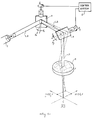
- the apparatus illustrated in Fig. 1 includes a laser 2 outputting a laser beam LB which is directed to a working surface WS, such as tissue to be surgically smoothed by ablation.
- the laser beam LB from laser 2 is first deflected by a mirror deflector device 3, then by a mirror deflector device 4, which directs the beam via a focusing lens 5 to the working surface WS.
- Mirror 3 is oscillated along one axis, e.g., the X-axis, by a first motor M 1 ; and mirror 4 is oscillated along the other orthogonal axis, e.g., the Y-axis, by a second motor M 2 .
- the two mirrors 3, 4 are located such that their axes (their normals Nx, Ny) are perpendicular to each other. Both motors are controlled by a control system, generally designated 6, in a manner to produce a homogenous scanning of the laser beam LB over the working surface WS, namely the tissue to be smoothed.
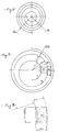
- Fig. 2 illustrates one of the oscillating mirrors, e.g., mirror 3, and its motor drive, e.g., motor M 1 .
- Motor M 1 is connected via its rotary shaft 10 to mirror 3.
- the mirror's normal vector Nx is perpendicular to axis 10.
- Two arms 11, 12 are connected to axis 10 and press against two springs 13, 14, which are connected to the motor's housing.
- the two springs 13, 14 produce opposite torques on the motor's shaft 10, so that the shaft is at angular equilibrium.
- V(t) V o Sin(2 ⁇ ft)
- V o the maximum value of voltage
- f the frequency
- t the time
- the motor together with the mirror, oscillates clockwise and counterclockwise according to the equation:
- ⁇ (t) ⁇ (V o , f)Sin(2 ⁇ ft+ ⁇ )
- ⁇ (V o ,f) the maximum displacement angle, which depends on V o and the frequency f: and ⁇ is the phase between the mechanical oscillations and the electrical voltage.
- the maximal displacement angle ⁇ (V o ,f) can be described as a function off and V o (see Fig. 3).
- Fig. 4 illustrates the deflection of a light beam by the scanner.
- a light beam strikes mirror 3 at an angle of 45°, the beam is reflected and returned at an angle of 45°.
- a lens 20 with a focal length of F is placed in the beam path, the beam will focus at a point O on the focal plane 21. This point O is referred to as the origin of the axis.
- the mirror rotates at an angle of ⁇ x
- the radius of the scanning can be controlled by changing ⁇ (V o ,f). This can be done by: (1) varying f when V o is constant, (2) by varying V o when f is constant, or (3) by varying both.
- a constant voltage amplitude V o with a curve described in Fig. 6 may be supplied to the two motors.
- the difference between two following scanning radii decreases, the energy per unit area increases.
- the difference between two consecutive scanning radii can be controlled by the rate of change of f. Since the frequency f is increased or decreased for each circular scanning, the difference between two consecutive circles will increase or decrease. Controlling the rate that frequency f is changed throughout each scanning, enables the control of radial energy distribution.
- S 1 and S 2 represent block areas.
- the area width always is the difference of radii between two consecutive scannings, and their height is the displacement L that the beam has traversed at unit time ⁇ t.
- the minimum diameter of the circular scans is equal to the diameter of the light beam LB, which is preferably at least 3.5 mm; and the diameters of the circular scans are varied such that they partially overlap the same amount:
- the sequence of frequencies (or matching time periods) in a phase difference of 90° are supplied by the control system 6 in Fig. 1 to the two motors M 1 , M 2 , thereby producing area scanning with uniform energy density for the entire area scanned.
- Power density may also be controlled by varying V o and keeping f constant, or by varying both. Any desired radial energy distribution may be programmed except for constant radial energy distribution.
- the scanning system may trace lissajous figures as disclosed in U.S. Patent No. 5,411,502.
- the mirrors are located with respect to the laser beam and also to each other to cyclically scan the laser beam along two orthogonal axes, and to cause the beam to trace a Lissajous pattern over the tissue to be smoothed.
- the ray exiting from the lens will scan at the focal plane an area whose limits are defined by a circle of radius 0.5 mm. Every 20 revolutions the ray completely scans the whole area and starts anew. The 20 revolution scan period is about 0.2 seconds and a lissajous pattern is achieved.
- the beam preferably travels through an optical waveguide before reaching the flash scanner.
- Fig. 9 depicts such an optical waveguide 10 through which a laser beam may travel.
- the laser beam is generated at laser source 12 and travels through the optical waveguide 14 in the direction of the arrows to the flash scanner 16 containing the reflector system.
- the optical waveguide which is loosely referred to as a fiber, provides superior waveguide capability for the laser beam. It also participates in defocusing the laser beam. After passing through the flash scanner, the laser beam is emitted to irradiate the skin surface (not shown here).
- the present invention permits all irradiated skin to be ablated with negligible thermal damage and char to the underlying skin. Moreover, any residual thermal damage is shallow and controlled.
- flash scanning in facial rejuvenation enables the smoothing of raised areas of the skin such as wrinkle shoulders around the mouth and eyes as well as scars and warts.
- the epidermal areas and underlying dermal layers are vaporized layer by layer.
- the treatment can be performed using a predetermined pattern of a spiral pattern or Lissajous figures.
- a spiral pattern is preferable for skin resurfacing as homogeneous vaporization is particularly desirable for cosmetic or aesthetic surgeries.
- the flash scanner is preferably used in conjunction with scanning for a predetermined scan time.
- the method of the present invention provides that the entire epidermal layer of skin of the affected area is ablated. Then ablation proceeds to the papillary dermal layer to a depth of about 70-200 microns, to above the collagen producing cells of the papillary dermis. At typical 7 watt laser operating power, for instance, depth is typically 70 microns with residual thermal damage to the subjacent dermis as low as 75-100 microns. The minimal thermal necrosis resulting to this portion of the dermal layer permits collagen production for smoothing out the skin so as to provide sufficient healing with substantially permanent results. Such favorable cosmetic or aesthetic treatments on otherwise healthy tissue is made possible by this technique.
- Rapid movement of the beam over the tissue ensures a 1-2 millisecond short duration of exposure on individual sites within the area. This is shorter than the thermal relaxation time of tissue for laser beam penetration depth of 30 micron at 10.6 ⁇ wavelength.
- the desired scan time is preprogrammed. Irradiation proceeds beginning at another location with minimal overlapping. In this manner the depth of irradiation can be accurately predetermined.
- the spot size of the laser beam on the skin may be from somewhat less than 0.20 mm diameter to 0.6 mm diameter.
- the area treated may, for instance, be up to 6 or 9 mm in diameter, with power requirements increasing accordingly.
- the method of the present invention is optimal for facial rejuvenation, for example, the smoothing of wrinkles.
- the method may also be used for skin rejuvenation as may be contemplated by those skilled in the art.
- the single layer vaporization depth was quantitatively estimated.
- a CO 2 laser was used in clinical cases which generated a focused beam somewhat less than 0.2 mm diameter on tissue.
- Using the laser at a power level of 7W for facial rejuvenation will generate an optical power density of above 100 W/mm 2 on tissue. This is considerably higher than the threshold for vaporization of tissue without residual carbon particles (the threshold for char-free tissue ablation is about 50 W/mm 2 ).
- the time required to homogeneously cover a round area was programmed to be 200 msec. During this time, the 7W operating laser delivers 1400mJ to the tissue.
- the entire procedure may be done in an office setting under local anesthesia and lasts 20 minutes on average.
Abstract
A method and apparatus for performing facial rejuvenation are provided in which ablation of an area of skin is accomplished to the papillary dermis, providing effective permanent smoothness.
Description
- The present invention achieves rejuvenation of skin with minimal thermal damage and carbonization to the papillary dermis. Indications include the smoothing or rejuvenation of perioral, lips and periorbital wrinkles, among others.
- Current treatments of the skin surface, whether for cosmetic or clinical applications, have not proven satisfactory. The most common current modalities of skin rejuvenation, namely chemical peeling and mechanical dermabrasion, suffer from lack of depth control and predictability. In addition, dermabrasion may result in bleeding which sends blood particles air-borne. Chemical peeling has the additional drawbacks of possible continued acid penetration after the chemicals are washed away and hypopigmentation.
- An object of the present invention is to provide a method, and also apparatus, of applying a laser beam to a working surface such as to produce a substantially homogenous distribution of the laser energy over the surface of skin to be smoothed, particularly for facial rejuvenation. There is provided a method of applying a laser beam to a working surface, comprising: displacing the laser beam to trace a plurality of circular scans over the surface to be smoothed; and continuously varying the diameters of the circular scans to produce a substantially homogenous distribution of the laser energy over the surface to be smoothed.
- According to further features in the preferred embodiments of the invention described below, the laser beam is displaced to trace the circular scans by deflecting the laser beam along two orthogonal axes by first and second deflector devices having axes perpendicular to each other, the deflector devices being oscillated by first and second motors operated at a phase difference of 90°. In the described preferred embodiment, the laser beam is of circular cross-section, and the minimum diameter of the circular scans is approximately equal to the diameter of the laser beam. Preferably, the diameter is at least 3.5 mm. The diameters of the circular scans are varied so that they partially overlap the same amount.
- As will be described more particularly below, the diameters may be continuously varied to produce the substantially homogenous distribution of the laser energy by varying the frequency of oscillation, maximum value of voltage, or both frequency of oscillation and maximum value of voltage, of the deflector devices.
- As will be shown more particularly below, the described method and apparatus enable homogenous scanning of the entire surface to be smoothed such as to make the method and apparatus particularly useful for the surgical smoothing of tissue by ablation while causing minimal thermal damage to the surrounding tissue, holes or cracks in the surrounding tissue, or char residue over the ablated area.
- A method of smoothing or rejuvenating a predetermined area of human skin is provided comprising ablating the epidermal layer of a predetermined area of human skin with a laser beam and further ablating a portion of the dermal layer originally underlying said ablated epidermal layer to the papillary dermis. The method further comprises cleaning the area ablated to provide a clean ablated area and protecting the clean ablated area.
- The method of smoothing a predetermined area of human skin involves, moreover, irradiating a portion of a predetermined area of human skin with a laser beam for a predetermined scan time to the papillary dermis, irradiating a next portion of said predetermined area of human skin for said predetermined scan time to the papillary dermis; and repeating the second and third steps such that the irradiating causes ablation of the skin uniformly.
- An objective of the present invention is to provide a method of facial rejuvenation which achieves depth control of ablation to the papillary dermis with minimal thermal damage.
- A further objective of the present invention is to provide a method of smoothing raised areas of skin which achieves depth control of ablation to the papillary dermis with minimal thermal damage.
- A number of embodiments of the invention will now be described, by way of example only, with reference to the accompanying drawings in which:
- Fig. 1 illustrates one form of apparatus constructed in accordance with an embodiment of the present invention;
- Figs. 2-8 are diagrams helpful in explaining the operation of the apparatus of Fig. 1;
- Fig. 9 depicts a fiber through which a laser beam may travel.
- A laser beam is employed to rejuvenate or smooth the skin.
- The embodiment of the present invention utilizes a laser preferably in conjunction with a flash scanner system. Flash scanner systems are described in U.S. Patent No. 5,411,502 entitled "A System for Causing Ablation of Irradiated Material of Living Tissue While Not Causing Damage Below a Predetermined Depth", and in the U.S. Patent Application No. 08/385,386 entitled "Method and Apparatus for Applying Laser Beam to a Working Surface, Particularly for Ablating Tissue". The flash scanner contains reflectors such as mirrors or prisms to reflect laser beams of light. The movements of the flash scanner are generally microprocessor controlled to provide the desired pattern of irradiation. The carbon dioxide laser is preferable for the uniform ablation of irradiated material. The laser beam of light may be emitted from articulated arm or, as provided herein, an optical waveguide. A focused or slightly defocused beam may be used.
- The apparatus illustrated in Fig. 1 includes a
laser 2 outputting a laser beam LB which is directed to a working surface WS, such as tissue to be surgically smoothed by ablation. The laser beam LB fromlaser 2 is first deflected by amirror deflector device 3, then by amirror deflector device 4, which directs the beam via a focusinglens 5 to the working surface WS.Mirror 3 is oscillated along one axis, e.g., the X-axis, by a first motor M1; andmirror 4 is oscillated along the other orthogonal axis, e.g., the Y-axis, by a second motor M2. The twomirrors - The following description, with reference particularly to Figs. 2-8, will explain how the motors M1, M2 are controlled to produce a homogenous scanning of the tissue to be smoothed.
- Fig. 2 illustrates one of the oscillating mirrors, e.g.,
mirror 3, and its motor drive, e.g., motor M1. Motor M1 is connected via itsrotary shaft 10 tomirror 3. The mirror's normal vector Nx is perpendicular toaxis 10. Twoarms axis 10 and press against twosprings springs shaft 10, so that the shaft is at angular equilibrium. - When the motor M1 is supplied with an electrical voltage V, it rotates the
mirror 3 against thesprings 13 14 until a new equilibrium is reached at a new angle φ in relation to the previous equilibrium point (φ = 0). A minus voltage (-V) will cause the motor and the mirror to rotate in the opposite direction at an angle of - φ. When the rate of voltage change is slow compared to the resonance frequency of the system, the angular displacement is linear to V; that is:
- When feeding the motor with alternating voltage, as described in the following equation:


- When using frequencies f, which are greater than the resonance frequency of the system, the maximal displacement angle φ(Vo ,f) can be described as a function off and Vo (see Fig. 3).
- Each of the functions φ(f) in Fig. 3 is ascribed to a different Vo. An increase in Vo will cause an increase in displacement amplitude. The variation of the displacement amplitude may be controlled by one of the following methods:
- 1. Keep Vo constant and vary f;
- 2. Keep f constant and vary Vo; or
- 3. Vary both Vo and f.
- Fig. 4 illustrates the deflection of a light beam by the scanner. When a light beam strikes mirror 3 at an angle of 45°, the beam is reflected and returned at an angle of 45°. If a
lens 20 with a focal length of F is placed in the beam path, the beam will focus at a point O on thefocal plane 21. This point O is referred to as the origin of the axis. When the mirror rotates at an angle of φx, the returned beam is reflected at an angle of 2φx and focused on the focal plane at point X, which is given by:
- When the two scanners are placed so that the two mirror normals Nx, Ny are perpendicular as shown in Fig. 1, voltage supplied to the two motors (M1, M2) will cause movement at the focal plane in both x and y directions as follows:


- The radius of the scanning can be controlled by changing φ(Vo,f). This can be done by: (1) varying f when Vo is constant, (2) by varying Vo when f is constant, or (3) by varying both.
- To scan a full area (not just the perimeter), a constant voltage amplitude Vo with a curve described in Fig. 6 may be supplied to the two motors. Operating the motors at a frequency f1 will cause rotational amplitude φ1 and circular scanning according to Equation (8) at a radius of
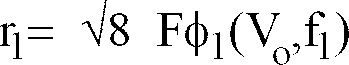

- On the focal plane, circles are formed with gradually decreasing radii from r1 to r2, thereby covering an area of a ring with an outer radius of r1 and an inner radius of r2 (see Fig. 6). Gradually decreasing the frequency to f1 will produce an area scanning with circles of gradually increasing radii to a radius of r1. Alternately varying frequencies between f1 and f2 will cause area scanning by means of continuously increasing and decreasing circles. The boundaries of the scanning (outer and inner radii) are determined by the extreme values of frequencies, f1 and f2. The control system 6 (Fig. 1) can be easily computerized such that the user selects the diameter of scanning, and the system determines the required frequencies according to the above equations.
- Since the difference between two following scanning radii decreases, the energy per unit area increases. The difference between two consecutive scanning radii can be controlled by the rate of change of f. Since the frequency f is increased or decreased for each circular scanning, the difference between two consecutive circles will increase or decrease. Controlling the rate that frequency f is changed throughout each scanning, enables the control of radial energy distribution.
- The scanned area is described in Fig. 8. S1 and S2 represent block areas. The area width always is the difference of radii between two consecutive scannings, and their height is the displacement L that the beam has traversed at unit time Δt. The displacement will be:

- P =
- laser power
- E =
- energy radiated onto block area S
- rn =
- radius of scanning corresponding to Sn
- Δrn =
- the difference between rn and the consecutive radius

- V(r) =
- linear velocity of the scanning beam
- Δt =
- time unit determined for all areas
- Ln =
- height of the block area corresponding to rn
- σn =
- energy density per unit time in a block area corresponding to radius rn
- The energy density may be calculated as follows:

- Assuming that the laser power is constant throughout scanning, the power density per unit area is proportional to 1/V(rn) Δrn. To achieve constant energy density for the entire scanning area (homogenous ablation), V(rn) Δrn should be kept constant. From Equation 9:

- Following is one procedure for producing a constant energy density wherein the frequency of the two motors M1, M2 is controlled by the control system 6 (Fig. 1). The minimum diameter of the circular scans is equal to the diameter of the light beam LB, which is preferably at least 3.5 mm; and the diameters of the circular scans are varied such that they partially overlap the same amount:
- 1) The minimum radius r2 is determined for the first scanning circle, according to the radius of the focused laser beam.
- 2) The first radii difference Δr1, between the first and second scanning circles, is determined at a value of 3/4 of the radius of the focused laser beam, so that the scanning circles overlap.
- 3) A curve φ(Vo,f) is determined by selecting Vo. From this curve, frequency f1 which corresponds to r1, and frequency f2 which corresponds to

- 4) The product

- 5) Δr2 is calculated from
Equation 12
- 6) The new radius is

- 7) Δr3 is calculated

- The sequence of frequencies (or matching time periods) in a phase difference of 90° are supplied by the
control system 6 in Fig. 1 to the two motors M1, M2, thereby producing area scanning with uniform energy density for the entire area scanned. - Power density may also be controlled by varying Vo and keeping f constant, or by varying both. Any desired radial energy distribution may be programmed except for constant radial energy distribution.
- Alternatively, the scanning system may trace lissajous figures as disclosed in U.S. Patent No. 5,411,502. In such a system the mirrors are located with respect to the laser beam and also to each other to cyclically scan the laser beam along two orthogonal axes, and to cause the beam to trace a Lissajous pattern over the tissue to be smoothed.
- Where the lens is placed perpendicular to the axis of the laser beam, a time dependent ray pattern will be produced at the focal plane of the lens (of focal length f), given by the following equations:

- For example, the lens may be of f=125 mm; the mirror wedge angle may be ⊖=2.34 mRad; and the angular velocities may be Ω1=600 rad/sec and Ω2=630 rad/-sec. Let


- With respect to performing laser facial rejuvenation, the beam preferably travels through an optical waveguide before reaching the flash scanner. Fig. 9 depicts such an
optical waveguide 10 through which a laser beam may travel. The laser beam is generated atlaser source 12 and travels through theoptical waveguide 14 in the direction of the arrows to theflash scanner 16 containing the reflector system. The optical waveguide, which is loosely referred to as a fiber, provides superior waveguide capability for the laser beam. It also participates in defocusing the laser beam. After passing through the flash scanner, the laser beam is emitted to irradiate the skin surface (not shown here). - The present invention permits all irradiated skin to be ablated with negligible thermal damage and char to the underlying skin. Moreover, any residual thermal damage is shallow and controlled.
- The use of flash scanning in facial rejuvenation enables the smoothing of raised areas of the skin such as wrinkle shoulders around the mouth and eyes as well as scars and warts. The epidermal areas and underlying dermal layers are vaporized layer by layer. The treatment can be performed using a predetermined pattern of a spiral pattern or Lissajous figures. A spiral pattern is preferable for skin resurfacing as homogeneous vaporization is particularly desirable for cosmetic or aesthetic surgeries. As described herein, the flash scanner is preferably used in conjunction with scanning for a predetermined scan time.
- The method of the present invention provides that the entire epidermal layer of skin of the affected area is ablated. Then ablation proceeds to the papillary dermal layer to a depth of about 70-200 microns, to above the collagen producing cells of the papillary dermis. At typical 7 watt laser operating power, for instance, depth is typically 70 microns with residual thermal damage to the subjacent dermis as low as 75-100 microns. The minimal thermal necrosis resulting to this portion of the dermal layer permits collagen production for smoothing out the skin so as to provide sufficient healing with substantially permanent results. Such favorable cosmetic or aesthetic treatments on otherwise healthy tissue is made possible by this technique.
- Rapid movement of the beam over the tissue ensures a 1-2 millisecond short duration of exposure on individual sites within the area. This is shorter than the thermal relaxation time of tissue for laser beam penetration depth of 30 micron at 10.6µ wavelength. The desired scan time is preprogrammed. Irradiation proceeds beginning at another location with minimal overlapping. In this manner the depth of irradiation can be accurately predetermined. The spot size of the laser beam on the skin may be from somewhat less than 0.20 mm diameter to 0.6 mm diameter. The area treated may, for instance, be up to 6 or 9 mm in diameter, with power requirements increasing accordingly.
- Advantageously, no bleeding results from the treatment. Following ablation, residual coagulated gray epidermal tissue is wiped off with sterile, saline soaked gauze to expose the dermal layer which is then protected and moisturized with dressings.
- The method of the present invention is optimal for facial rejuvenation, for example, the smoothing of wrinkles. The method may also be used for skin rejuvenation as may be contemplated by those skilled in the art.
- In the following manner the single layer vaporization depth was quantitatively estimated. A CO2 laser was used in clinical cases which generated a focused beam somewhat less than 0.2 mm diameter on tissue. Using the laser at a power level of 7W for facial rejuvenation will generate an optical power density of above 100 W/mm2 on tissue. This is considerably higher than the threshold for vaporization of tissue without residual carbon particles (the threshold for char-free tissue ablation is about 50 W/mm2 ). The time required to homogeneously cover a round area was programmed to be 200 msec. During this time, the 7W operating laser delivers 1400mJ to the tissue. Since the typical energy required to completely ablate tissue is about 3000mJ for 1mm3 volume, keeping the facial skin resurfacing handpiece precisely on a single site for 0.2 sec will generate a clean charfree crater of less than 70 micrometer depth for 3mm diameter scanned area. Minimal residual thermal reaction resulted to the papillary an reticular dermis. No damage occurred to adnexal structures. Histologies of excised facial skins ablated as described also showed that the thermal subcrater necrosis depth was less than 150µm.
- Over 50 skin exfoliations were performed to smooth out perioral, lip and periorbital wrinkles and scars. The laser power level was set to approximately 7 Watts, although the precise power level selected depended on the skin thickness in conjunction with skin darkness and hair color. In treating wrinkles, the "shoulders" were ablated along both sides of the wrinkles by spiral pattern with caution to avoid overlapping treatment spots and thus avoid ablation of the papillary dermis. The laser repeat mode was used with the laser set to 0.2 sec "on time" and 0.4 sec "off time." Following ablation, residual coagulated gray epidermal tissue was wiped off with sterile, saline soaked gauze to expose the dermal layer which was then protected and moisturized with dressings. Full healing was attained within three months. No permanent hyer- or hypo- pigmentation was observed, although the skin appeared characteristically "pink" for about six weeks.
- The entire procedure may be done in an office setting under local anesthesia and lasts 20 minutes on average.
Claims (17)
- A method of smoothing a predetermined area of human skin comprising:
scanning the epidermal layer of said predetermined area of human skin sequentially and continuously with a laser beam; and
scanning a portion of the dermal layer underlying said ablated epidermal layer to the papillary dermis such that collagen producing cells of the papillary dermis retain the capability of collagen production. - The method as claimed in Claim 1 further comprising:
cleaning the area scanned to provide a clean scanned area; and
protecting said clean scanned area. - A method of smoothing a predetermined area of human skin comprising:
scanning a portion of said predetermined area of human skin continuously with a laser beam for a predetermined scan time to the papillary dermis such that the collagen producing cells of the papillary dermis underlying said portion of a predetermined area of human skin retain the capability of collagen production; and
scanning a next portion of said predetermined area of human skin continuously with a laser beam for a predetermined scan time to the papillary dermis such that the collagen producing cells of the papillary dermis underlying said next portion of a predetermined area of human skin retain the capability of collagen production. - The method as claimed in Claim 1 in which said laser is a carbon dioxide laser.
- The method as claimed in Claim 3 in which said laser is a carbon dioxide laser.
- The method as claimed in Claim 1 further comprising passing a laser beam through an optical waveguide prior to scanning said epidermal layer with said laser beam.
- The method as claimed in Claim 3 further comprising passing a laser beam through an optical waveguide prior to scanning said laser beam.
- The method as claimed in Claim 1 in which said dermal layer is ablated to a depth of about 70-200 microns.
- The method as claimed in Claim 3 in which the dermal layer of each portion of human skin scanned is ablated to a depth of about 70-200 microns.
- An apparatus suitable for smoothing a predetermined area of human skin comprising:
a laser for providing a laser beam; and
a flashscanner capable of scanning said beam continuously over a predetermined area of human skin to the papillary dermis such that the collagen producing cells of the papillary dermis retain the capability of collagen production. - The apparatus as claimed in Claim 10 in which the dermal layer is ablated to a depth of between about 70-200 microns.
- The apparatus as claimed in Claim 10 in which thermal damage occurs to the subjacent dermis to a depth of 75-100 microns.
- The apparatus as claimed in Claim 10 in which said laser is a carbon dioxide laser.
- The apparatus as claimed in Claim 13 in which said laser is powered at 7 Watts.
- The apparatus as claimed in Claim 10 in which said flashscanner scans said beam in a spiral pattern.
- The apparatus as claimed in Claim 10 further comprising an optical waveguide capable of guiding the laser beam to said predetermined area of human skin.
- An apparatus suitable for smoothing a predetermined area of human skin comprising:
a laser for providing a laser beam; and
a flashscanner capable of scanning said beam continuously and sequentially over a portion of said predetermined area of human skin to the papillary dermis such that the collagen producing cells of the papillary dermis underlying said portion of a predetermined area of human skin retain the capability of collagen production, where said flashscanner is capable of said scanning of said beam over a plurality of portions of said predetermined area of human skin.
Applications Claiming Priority (2)
| Application Number | Priority Date | Filing Date | Title |
|---|---|---|---|
| US08/382,918 US5611795A (en) | 1995-02-03 | 1995-02-03 | Laser facial rejuvenation |
| US382918 | 1995-02-03 |
Publications (1)
| Publication Number | Publication Date |
|---|---|
| EP0724866A1 true EP0724866A1 (en) | 1996-08-07 |
Family
ID=23510968
Family Applications (1)
| Application Number | Title | Priority Date | Filing Date |
|---|---|---|---|
| EP96300692A Withdrawn EP0724866A1 (en) | 1995-02-03 | 1996-01-31 | Laser facial rejuvenation |
Country Status (6)
| Country | Link |
|---|---|
| US (2) | US5611795A (en) |
| EP (1) | EP0724866A1 (en) |
| JP (1) | JPH09253225A (en) |
| KR (1) | KR970061288A (en) |
| AU (1) | AU4215596A (en) |
| CA (1) | CA2168276A1 (en) |
Cited By (12)
| Publication number | Priority date | Publication date | Assignee | Title |
|---|---|---|---|---|
| US5743902A (en) * | 1995-01-23 | 1998-04-28 | Coherent, Inc. | Hand-held laser scanner |
| WO1998025528A1 (en) * | 1996-12-10 | 1998-06-18 | Asah Medico A/S | An apparatus for cosmetic tissue treatment |
| WO1998033558A1 (en) * | 1997-02-05 | 1998-08-06 | Candela Corporation | Method and apparatus for treating wrinkles in skin using radiation |
| EP0933096A3 (en) * | 1998-01-29 | 1999-11-03 | International Business Machines Corporation | Laser for dermal ablation |
| US6190376B1 (en) | 1996-12-10 | 2001-02-20 | Asah Medico A/S | Apparatus for tissue treatment |
| ES2167252A1 (en) * | 2000-07-13 | 2002-05-01 | Villacampa Francisco J Arcusa | Procedure for laser treatment of tissue |
| US6436094B1 (en) | 2000-03-16 | 2002-08-20 | Laserscope, Inc. | Electromagnetic and laser treatment and cooling device |
| US6607523B1 (en) | 1999-03-19 | 2003-08-19 | Asah Medico A/S | Apparatus for tissue treatment |
| US7891362B2 (en) | 2005-12-23 | 2011-02-22 | Candela Corporation | Methods for treating pigmentary and vascular abnormalities in a dermal region |
| US8246611B2 (en) | 2006-06-14 | 2012-08-21 | Candela Corporation | Treatment of skin by spatial modulation of thermal heating |
| US8277495B2 (en) | 2005-01-13 | 2012-10-02 | Candela Corporation | Method and apparatus for treating a diseased nail |
| US9028469B2 (en) | 2005-09-28 | 2015-05-12 | Candela Corporation | Method of treating cellulite |
Families Citing this family (46)
| Publication number | Priority date | Publication date | Assignee | Title |
|---|---|---|---|---|
| US6024733A (en) * | 1995-06-07 | 2000-02-15 | Arthrocare Corporation | System and method for epidermal tissue ablation |
| US6056738A (en) * | 1997-01-31 | 2000-05-02 | Transmedica International, Inc. | Interstitial fluid monitoring |
| US5611795A (en) * | 1995-02-03 | 1997-03-18 | Laser Industries, Ltd. | Laser facial rejuvenation |
| US5879376A (en) * | 1995-07-12 | 1999-03-09 | Luxar Corporation | Method and apparatus for dermatology treatment |
| US6161546A (en) * | 1995-07-17 | 2000-12-19 | Quardrivium, L.L.C. | System for altering tissue beneath an outer layer of tissue |
| US6009876A (en) * | 1997-05-20 | 2000-01-04 | Yavitz; Edward Q. | Method for modifying and reshaping collagen beneath the surface of skin |
| US5820624A (en) * | 1995-07-17 | 1998-10-13 | Quadrivium, L.L.C. | System for altering corneal tissue |
| US5964749A (en) * | 1995-09-15 | 1999-10-12 | Esc Medical Systems Ltd. | Method and apparatus for skin rejuvenation and wrinkle smoothing |
| US7758537B1 (en) | 1995-11-22 | 2010-07-20 | Arthrocare Corporation | Systems and methods for electrosurgical removal of the stratum corneum |
| US5630811A (en) * | 1996-03-25 | 1997-05-20 | Miller; Iain D. | Method and apparatus for hair removal |
| US6096029A (en) * | 1997-02-24 | 2000-08-01 | Laser Skin Toner, Inc. | Laser method for subsurface cutaneous treatment |
| US6171302B1 (en) * | 1997-03-19 | 2001-01-09 | Gerard Talpalriu | Apparatus and method including a handpiece for synchronizing the pulsing of a light source |
| US6235015B1 (en) * | 1997-05-14 | 2001-05-22 | Applied Optronics Corporation | Method and apparatus for selective hair depilation using a scanned beam of light at 600 to 1000 nm |
| US5968033A (en) * | 1997-11-03 | 1999-10-19 | Fuller Research Corporation | Optical delivery system and method for subsurface tissue irradiation |
| US6575964B1 (en) | 1998-02-03 | 2003-06-10 | Sciton, Inc. | Selective aperture for laser delivery system for providing incision, tissue ablation and coagulation |
| US6544256B1 (en) | 1998-04-24 | 2003-04-08 | Biolase Technology, Inc. | Electromagnetically induced cutting with atomized fluid particles for dermatological applications |
| US6077294A (en) | 1998-06-11 | 2000-06-20 | Cynosure, Inc. | Method for non-invasive wrinkle removal and skin treatment |
| US6059820A (en) | 1998-10-16 | 2000-05-09 | Paradigm Medical Corporation | Tissue cooling rod for laser surgery |
| US6235039B1 (en) | 1999-02-23 | 2001-05-22 | Roger C. Parkin | Skin abrasion device |
| US6432113B1 (en) | 1999-02-23 | 2002-08-13 | Roger C. Parkin | Skin abrasion device |
| US7041094B2 (en) * | 1999-03-15 | 2006-05-09 | Cutera, Inc. | Tissue treatment device and method |
| US6383176B1 (en) | 1999-03-15 | 2002-05-07 | Altus Medical, Inc. | Hair removal device and method |
| US6569155B1 (en) | 1999-03-15 | 2003-05-27 | Altus Medical, Inc. | Radiation delivery module and dermal tissue treatment method |
| US6808532B2 (en) * | 2000-12-15 | 2004-10-26 | Dan E. Andersen | Laser treatment for reducing wrinkles |
| US6743221B1 (en) * | 2001-03-13 | 2004-06-01 | James L. Hobart | Laser system and method for treatment of biological tissues |
| US6770069B1 (en) | 2001-06-22 | 2004-08-03 | Sciton, Inc. | Laser applicator |
| US20040082940A1 (en) * | 2002-10-22 | 2004-04-29 | Michael Black | Dermatological apparatus and method |
| US20030216719A1 (en) * | 2001-12-12 | 2003-11-20 | Len Debenedictis | Method and apparatus for treating skin using patterns of optical energy |
| BR0312430A (en) | 2002-06-19 | 2005-04-26 | Palomar Medical Tech Inc | Method and apparatus for treating skin and subcutaneous conditions |
| US6991644B2 (en) * | 2002-12-12 | 2006-01-31 | Cutera, Inc. | Method and system for controlled spatially-selective epidermal pigmentation phototherapy with UVA LEDs |
| ES2441408T3 (en) | 2003-03-27 | 2014-02-04 | The General Hospital Corporation | Device for dermatological treatment and fractional skin rejuvenation |
| JP2007531544A (en) * | 2003-07-11 | 2007-11-08 | リライアント・テクノロジーズ・インコーポレイテッド | Method and apparatus for fractionated light treatment of skin |
| US7291140B2 (en) * | 2003-07-18 | 2007-11-06 | Cutera, Inc. | System and method for low average power dermatologic light treatment device |
| US8915906B2 (en) * | 2003-08-25 | 2014-12-23 | Cutera, Inc. | Method for treatment of post-partum abdominal skin redundancy or laxity |
| US8870856B2 (en) * | 2003-08-25 | 2014-10-28 | Cutera, Inc. | Method for heating skin using light to provide tissue treatment |
| US7722600B2 (en) | 2003-08-25 | 2010-05-25 | Cutera, Inc. | System and method for heating skin using light to provide tissue treatment |
| US7326199B2 (en) * | 2003-12-22 | 2008-02-05 | Cutera, Inc. | System and method for flexible architecture for dermatologic treatments utilizing multiple light sources |
| US7413572B2 (en) * | 2004-06-14 | 2008-08-19 | Reliant Technologies, Inc. | Adaptive control of optical pulses for laser medicine |
| US7856985B2 (en) | 2005-04-22 | 2010-12-28 | Cynosure, Inc. | Method of treatment body tissue using a non-uniform laser beam |
| WO2007095183A2 (en) * | 2006-02-13 | 2007-08-23 | Reliant Technologies, Inc. | Laser system for treatment of skin laxity |
| US7586957B2 (en) | 2006-08-02 | 2009-09-08 | Cynosure, Inc | Picosecond laser apparatus and methods for its operation and use |
| WO2010022330A2 (en) * | 2008-08-21 | 2010-02-25 | University Of Florida Research Foundation, Inc. | Differential laser-induced perturbation (dlip) for bioimaging and chemical sensing |
| EP2839552A4 (en) | 2012-04-18 | 2015-12-30 | Cynosure Inc | Picosecond laser apparatus and methods for treating target tissues with same |
| US10285757B2 (en) | 2013-03-15 | 2019-05-14 | Cynosure, Llc | Picosecond optical radiation systems and methods of use |
| WO2019165426A1 (en) | 2018-02-26 | 2019-08-29 | Cynosure, Inc. | Q-switched cavity dumped sub-nanosecond laser |
| KR102239058B1 (en) * | 2020-09-02 | 2021-04-13 | 주식회사 위즈메디 | Apparatus for irradiating light |
Citations (3)
| Publication number | Priority date | Publication date | Assignee | Title |
|---|---|---|---|---|
| EP0172490A1 (en) * | 1984-08-07 | 1986-02-26 | Medical Laser Research And Development Corporation | Laser system for providing target specific energy deposition and damage |
| US5336217A (en) * | 1986-04-24 | 1994-08-09 | Institut National De La Sante Et De La Recherche Medicale (Insepm) | Process for treatment by irradiating an area of a body, and treatment apparatus usable in dermatology for the treatment of cutaneous angio dysplasias |
| WO1994026203A1 (en) * | 1993-05-07 | 1994-11-24 | British Technology Group Limited | Apparatus and method for delivering laser radiation to a substrate |
Family Cites Families (24)
| Publication number | Priority date | Publication date | Assignee | Title |
|---|---|---|---|---|
| US3884236A (en) * | 1971-10-28 | 1975-05-20 | Mikhail M Krasnov | Method of glaucoma treatment |
| US4469098A (en) * | 1978-12-18 | 1984-09-04 | Davi Samantha K | Apparatus for and method of utilizing energy to excise pathological tissue |
| SU1073914A1 (en) * | 1981-06-04 | 1985-06-30 | Предприятие П/Я Г-4147 | Method of incision of biolgical tissues and device for effecting same |
| JPS59115032A (en) * | 1982-12-23 | 1984-07-03 | 東北リコ−株式会社 | Blood vessel connector |
| IL67599A (en) * | 1982-12-31 | 1986-09-30 | Laser Ind Ltd | Control apparatus particularly useful for controlling a laser |
| US4672969A (en) * | 1983-10-06 | 1987-06-16 | Sonomo Corporation | Laser healing method |
| US4566503A (en) * | 1983-12-13 | 1986-01-28 | Martin G. Heller | Apparatus and method of setting up apparatus for shaping and trimming the leads of integrated components |
| US4775361A (en) * | 1986-04-10 | 1988-10-04 | The General Hospital Corporation | Controlled removal of human stratum corneum by pulsed laser to enhance percutaneous transport |
| US4917083A (en) * | 1988-03-04 | 1990-04-17 | Heraeus Lasersonics, Inc. | Delivery arrangement for a laser medical system |
| US5057104A (en) * | 1989-05-30 | 1991-10-15 | Cyrus Chess | Method and apparatus for treating cutaneous vascular lesions |
| JPH05505737A (en) * | 1990-03-14 | 1993-08-26 | キャンデラ・コーポレーション | Apparatus and method for treating pigmented lesions using pulsed radiation |
| US5071417A (en) * | 1990-06-15 | 1991-12-10 | Rare Earth Medical Lasers, Inc. | Laser fusion of biological materials |
| US5280378A (en) * | 1990-10-19 | 1994-01-18 | I.L. Med, Inc. | Cyclically scanned medical laser |
| US5474549A (en) * | 1991-07-09 | 1995-12-12 | Laserscope | Method and system for scanning a laser beam for controlled distribution of laser dosage |
| US5217455A (en) * | 1991-08-12 | 1993-06-08 | Tan Oon T | Laser treatment method for removing pigmentations, lesions, and abnormalities from the skin of a living human |
| US5423803A (en) * | 1991-10-29 | 1995-06-13 | Thermotrex Corporation | Skin surface peeling process using laser |
| US5226907A (en) * | 1991-10-29 | 1993-07-13 | Tankovich Nikolai I | Hair removal device and method |
| US5344418A (en) * | 1991-12-12 | 1994-09-06 | Shahriar Ghaffari | Optical system for treatment of vascular lesions |
| IL100664A0 (en) * | 1992-01-15 | 1992-09-06 | Laser Ind Ltd | Method and apparatus for controlling a laser beam |
| US5527350A (en) * | 1993-02-24 | 1996-06-18 | Star Medical Technologies, Inc. | Pulsed infrared laser treatment of psoriasis |
| IL108059A (en) * | 1993-12-17 | 1998-02-22 | Laser Ind Ltd | Method and apparatus for applying laser beams to a working surface, particularly for ablating tissue |
| US5464436A (en) * | 1994-04-28 | 1995-11-07 | Lasermedics, Inc. | Method of performing laser therapy |
| US5624434A (en) * | 1995-02-03 | 1997-04-29 | Laser Industries, Ltd. | Laser preparation of recipient holes for graft implantation in the treatment of icepick scars |
| US5611795A (en) * | 1995-02-03 | 1997-03-18 | Laser Industries, Ltd. | Laser facial rejuvenation |
-
1995
- 1995-02-03 US US08/382,918 patent/US5611795A/en not_active Expired - Lifetime
-
1996
- 1996-01-25 AU AU42155/96A patent/AU4215596A/en not_active Abandoned
- 1996-01-29 CA CA002168276A patent/CA2168276A1/en not_active Abandoned
- 1996-01-31 EP EP96300692A patent/EP0724866A1/en not_active Withdrawn
- 1996-02-02 KR KR1019960002586A patent/KR970061288A/en not_active Application Discontinuation
- 1996-02-02 JP JP8040657A patent/JPH09253225A/en active Pending
- 1996-10-25 US US08/738,305 patent/US5807386A/en not_active Expired - Lifetime
Patent Citations (3)
| Publication number | Priority date | Publication date | Assignee | Title |
|---|---|---|---|---|
| EP0172490A1 (en) * | 1984-08-07 | 1986-02-26 | Medical Laser Research And Development Corporation | Laser system for providing target specific energy deposition and damage |
| US5336217A (en) * | 1986-04-24 | 1994-08-09 | Institut National De La Sante Et De La Recherche Medicale (Insepm) | Process for treatment by irradiating an area of a body, and treatment apparatus usable in dermatology for the treatment of cutaneous angio dysplasias |
| WO1994026203A1 (en) * | 1993-05-07 | 1994-11-24 | British Technology Group Limited | Apparatus and method for delivering laser radiation to a substrate |
Non-Patent Citations (1)
| Title |
|---|
| GREEN ET AL.: "Pulsed Carbon Dioxide Laser Ablation of Burned Skin", LASERS IN SURGERY AND MEDICINE, vol. 10, no. 5, 1990, NEW YORK, pages 476 - 484, XP000385914 * |
Cited By (19)
| Publication number | Priority date | Publication date | Assignee | Title |
|---|---|---|---|---|
| US5957915A (en) * | 1995-01-23 | 1999-09-28 | Coherent, Inc. | Hand-held laser scanner |
| US5743902A (en) * | 1995-01-23 | 1998-04-28 | Coherent, Inc. | Hand-held laser scanner |
| US6328733B1 (en) | 1995-01-23 | 2001-12-11 | Lumenis Inc. | Hand-held laser scanner |
| US6533776B2 (en) | 1996-12-10 | 2003-03-18 | Asah Medico A/S | Apparatus for tissue treatment |
| WO1998025528A1 (en) * | 1996-12-10 | 1998-06-18 | Asah Medico A/S | An apparatus for cosmetic tissue treatment |
| US6190376B1 (en) | 1996-12-10 | 2001-02-20 | Asah Medico A/S | Apparatus for tissue treatment |
| WO1998033558A1 (en) * | 1997-02-05 | 1998-08-06 | Candela Corporation | Method and apparatus for treating wrinkles in skin using radiation |
| US6120497A (en) * | 1997-02-05 | 2000-09-19 | Massachusetts General Hospital | Method and apparatus for treating wrinkles in skin using radiation |
| US6659999B1 (en) | 1997-02-05 | 2003-12-09 | Candela Corporation | Method and apparatus for treating wrinkles in skin using radiation |
| EP0933096A3 (en) * | 1998-01-29 | 1999-11-03 | International Business Machines Corporation | Laser for dermal ablation |
| US6165170A (en) * | 1998-01-29 | 2000-12-26 | International Business Machines Corporation | Laser dermablator and dermablation |
| US6607523B1 (en) | 1999-03-19 | 2003-08-19 | Asah Medico A/S | Apparatus for tissue treatment |
| US6436094B1 (en) | 2000-03-16 | 2002-08-20 | Laserscope, Inc. | Electromagnetic and laser treatment and cooling device |
| ES2167252A1 (en) * | 2000-07-13 | 2002-05-01 | Villacampa Francisco J Arcusa | Procedure for laser treatment of tissue |
| US8277495B2 (en) | 2005-01-13 | 2012-10-02 | Candela Corporation | Method and apparatus for treating a diseased nail |
| US9028469B2 (en) | 2005-09-28 | 2015-05-12 | Candela Corporation | Method of treating cellulite |
| US7891362B2 (en) | 2005-12-23 | 2011-02-22 | Candela Corporation | Methods for treating pigmentary and vascular abnormalities in a dermal region |
| US8246611B2 (en) | 2006-06-14 | 2012-08-21 | Candela Corporation | Treatment of skin by spatial modulation of thermal heating |
| US9486285B2 (en) | 2006-06-14 | 2016-11-08 | Candela Corporation | Treatment of skin by spatial modulation of thermal heating |
Also Published As
| Publication number | Publication date |
|---|---|
| JPH09253225A (en) | 1997-09-30 |
| US5807386A (en) | 1998-09-15 |
| CA2168276A1 (en) | 1996-08-04 |
| KR970061288A (en) | 1997-09-12 |
| AU4215596A (en) | 1996-08-15 |
| US5611795A (en) | 1997-03-18 |
Similar Documents
| Publication | Publication Date | Title |
|---|---|---|
| EP0724866A1 (en) | Laser facial rejuvenation | |
| US8308717B2 (en) | Thermal energy applicator | |
| US5938657A (en) | Apparatus for delivering energy within continuous outline | |
| US5582752A (en) | Method and apparatus for applying laser beams to a working surface, particularly for ablating tissue | |
| US5546214A (en) | Method and apparatus for treating a surface with a scanning laser beam having an improved intensity cross-section | |
| AU2010214810B2 (en) | Method and apparatus for therapeutic EMR treatment of the skin | |
| US5906609A (en) | Method for delivering energy within continuous outline | |
| US7101365B1 (en) | Laser for skin treatment | |
| US6149644A (en) | Method and apparatus for epidermal treatment with computer controlled moving focused infrared light | |
| EP1031324B1 (en) | Laser depilation apparatus | |
| US8246613B2 (en) | Method and apparatus of treating tissue | |
| CA2164157A1 (en) | Apparatus for hair transplantation using a scanning continuous-working co2 laser and the use of the apparatus for hair transplantation | |
| US20070239079A1 (en) | Method and apparatus for selective treatment of biological tissue using ultrasound energy | |
| US11406450B2 (en) | Device for irradiating the skin | |
| WO2007007336A1 (en) | Laser ablation apparatus useful for hard tissue removal | |
| CHERNOFF et al. | SilkTouch: a new technology for skin resurfacing in aesthetic surgery | |
| US5995265A (en) | Method and apparatus for treating a surface with a scanning laser beam having an improved intensity cross-section | |
| US5624434A (en) | Laser preparation of recipient holes for graft implantation in the treatment of icepick scars | |
| KR20110015986A (en) | Laser beam irradiator for skin treatment and laser beam irradiation method | |
| WO1998025528A1 (en) | An apparatus for cosmetic tissue treatment | |
| RU2163790C1 (en) | Scanning system | |
| WO1998024512A1 (en) | Grid zones successive irradiation | |
| IL180030A (en) | Thermal energy applicator |
Legal Events
| Date | Code | Title | Description |
|---|---|---|---|
| PUAI | Public reference made under article 153(3) epc to a published international application that has entered the european phase |
Free format text: ORIGINAL CODE: 0009012 |
|
| AK | Designated contracting states |
Kind code of ref document: A1 Designated state(s): DE GB IT |
|
| 17P | Request for examination filed |
Effective date: 19961128 |
|
| 17Q | First examination report despatched |
Effective date: 19970828 |
|
| STAA | Information on the status of an ep patent application or granted ep patent |
Free format text: STATUS: THE APPLICATION IS DEEMED TO BE WITHDRAWN |
|
| 18D | Application deemed to be withdrawn |
Effective date: 19990127 |