EP0725486B1 - Transmission code having local parity - Google Patents
Transmission code having local parity Download PDFInfo
- Publication number
- EP0725486B1 EP0725486B1 EP96100861A EP96100861A EP0725486B1 EP 0725486 B1 EP0725486 B1 EP 0725486B1 EP 96100861 A EP96100861 A EP 96100861A EP 96100861 A EP96100861 A EP 96100861A EP 0725486 B1 EP0725486 B1 EP 0725486B1
- Authority
- EP
- European Patent Office
- Prior art keywords
- disparity
- bit
- code
- frame
- bit bytes
- Prior art date
- Legal status (The legal status is an assumption and is not a legal conclusion. Google has not performed a legal analysis and makes no representation as to the accuracy of the status listed.)
- Expired - Lifetime
Links
- 230000005540 biological transmission Effects 0.000 title description 18
- 230000000295 complement effect Effects 0.000 claims description 33
- 238000000034 method Methods 0.000 claims description 29
- 230000001419 dependent effect Effects 0.000 claims description 23
- 239000013598 vector Substances 0.000 description 23
- 238000012937 correction Methods 0.000 description 20
- 230000007704 transition Effects 0.000 description 11
- 239000000835 fiber Substances 0.000 description 8
- 239000011159 matrix material Substances 0.000 description 8
- 238000001514 detection method Methods 0.000 description 6
- 238000013461 design Methods 0.000 description 5
- 230000003595 spectral effect Effects 0.000 description 5
- 238000010586 diagram Methods 0.000 description 3
- 230000000630 rising effect Effects 0.000 description 3
- 230000002411 adverse Effects 0.000 description 2
- 238000013459 approach Methods 0.000 description 2
- 230000008901 benefit Effects 0.000 description 2
- 230000008878 coupling Effects 0.000 description 2
- 238000010168 coupling process Methods 0.000 description 2
- 238000005859 coupling reaction Methods 0.000 description 2
- 125000004122 cyclic group Chemical group 0.000 description 2
- 230000000694 effects Effects 0.000 description 2
- 230000004399 eye closure Effects 0.000 description 2
- 230000006870 function Effects 0.000 description 2
- 230000005291 magnetic effect Effects 0.000 description 2
- 238000013507 mapping Methods 0.000 description 2
- 238000011084 recovery Methods 0.000 description 2
- 238000001228 spectrum Methods 0.000 description 2
- 230000009466 transformation Effects 0.000 description 2
- 238000013519 translation Methods 0.000 description 2
- 238000007476 Maximum Likelihood Methods 0.000 description 1
- 241000648484 Nymphalis l-album Species 0.000 description 1
- 230000004075 alteration Effects 0.000 description 1
- 230000015556 catabolic process Effects 0.000 description 1
- 230000008859 change Effects 0.000 description 1
- 238000012512 characterization method Methods 0.000 description 1
- 238000006731 degradation reaction Methods 0.000 description 1
- 230000001934 delay Effects 0.000 description 1
- 238000005516 engineering process Methods 0.000 description 1
- 238000011156 evaluation Methods 0.000 description 1
- 230000003993 interaction Effects 0.000 description 1
- 230000007246 mechanism Effects 0.000 description 1
- 230000003287 optical effect Effects 0.000 description 1
- 230000008569 process Effects 0.000 description 1
- 238000012545 processing Methods 0.000 description 1
- 230000009467 reduction Effects 0.000 description 1
- 238000005070 sampling Methods 0.000 description 1
- 230000011218 segmentation Effects 0.000 description 1
- 238000007493 shaping process Methods 0.000 description 1
- 230000011664 signaling Effects 0.000 description 1
- 238000004088 simulation Methods 0.000 description 1
- 239000013589 supplement Substances 0.000 description 1
- 238000012546 transfer Methods 0.000 description 1
Images


Classifications
-
- H—ELECTRICITY
- H03—ELECTRONIC CIRCUITRY
- H03M—CODING; DECODING; CODE CONVERSION IN GENERAL
- H03M13/00—Coding, decoding or code conversion, for error detection or error correction; Coding theory basic assumptions; Coding bounds; Error probability evaluation methods; Channel models; Simulation or testing of codes
- H03M13/03—Error detection or forward error correction by redundancy in data representation, i.e. code words containing more digits than the source words
- H03M13/05—Error detection or forward error correction by redundancy in data representation, i.e. code words containing more digits than the source words using block codes, i.e. a predetermined number of check bits joined to a predetermined number of information bits
- H03M13/09—Error detection only, e.g. using cyclic redundancy check [CRC] codes or single parity bit
- H03M13/095—Error detection codes other than CRC and single parity bit codes
-
- H—ELECTRICITY
- H03—ELECTRONIC CIRCUITRY
- H03M—CODING; DECODING; CODE CONVERSION IN GENERAL
- H03M5/00—Conversion of the form of the representation of individual digits
- H03M5/02—Conversion to or from representation by pulses
- H03M5/04—Conversion to or from representation by pulses the pulses having two levels
- H03M5/14—Code representation, e.g. transition, for a given bit cell depending on the information in one or more adjacent bit cells, e.g. delay modulation code, double density code
- H03M5/145—Conversion to or from block codes or representations thereof
Definitions
- the present invention is directed to an apparatus and method for generating coded data from uncoded data using a code having local parity and a unique and singular comma.
- transmission codes The primary purpose of transmission codes is to transform the frequency spectrum of a serial data stream so that clocking can be recovered readily and AC coupling is possible.
- the code must also provide special characters outside the data alphabet for functions such as character synchronization, frame delimiters and perhaps for abort, reset, idle, diagnostics, etc. Codes are also used, often in combination with signal waveform shaping, to adapt the signal spectrum more closely to specific channel requirements. In most cases, a reduction in bandwidth by constraints on both the high and the low frequency components is desirable to reduce distortion in the transmission media, especially electromagnetic cables, or in the band limited receiver, and to reduce the effects of extrinsic and intrinsic noise.
- Such codes generally exhibit the undesirable feature of enlarging error bursts in the decoded data, making detection by a cyclic redundancy check more difficult.
- a good transmission code should minimize these effects.
- the task force considered the outlines of a specific FEC proposal. A more detailed description is now available in the literature [Benz et al., 1991; McMahon et al, 1992; Springer, 1992].
- the proposal included a table lookup 8B/10B code and an 8 bit shortened Hamming code applied to the coded bits for every 8 information bytes.
- the FEC bits are Manchester coded. One pair of such coded bits is inserted between the 8B/10B coded bytes.
- the data transfer rate is reduced from 0.8 to 0.667. A single error in 8 data bytes can always be corrected.
- GB-A-2 232 858 discloses a method and data coding apparatus for encoding data in which 8-bit data bytes are encoded as 10-bit code blocks, whereby the code blocks satisfy the following rules:
- Each code block contains either 5 bits of a first predetermined binary value and 5 bits of a second predetermined binary value, or 4 bits of the first binary value and 6 bits o the second binary value.
- No code block has more than 4 contiguous bits of the first binary value or more than 4 contiguous bits of the second binary value.
- Each code block has at least one transition in its first three bits and at least one transition in its last three bits.
- Each code block contains at least four transitions, and each code block contains at least two transitions in its first six bits and at least two transitions in its last six bits.
- Alternate disparate code blocks i.e., code blocks containing 4 bits of the first binary value and 6 bits of the second binary value, are inverted to maintain an overall balance between ones and zeros in the encoded data.
- the 10-bit blocks 1000011110 and 0111100001 are
- EP-A-0 097 763 discloses a method and a data encoding apparatus for producing a DC balanced run length limited rate 8B/10B code from an unconstrained input data stream comprising a multiplicity of 8 bit data blocks.
- the 8-bit block is partitioned into two sub-blocks consisting of 5 and 3 contiguous bits, whereby each sub-block is examined in order to determine if any of the individual bits require alteration. If yes, the predetermined bits are altered based on said determination in order to produce an alternate code pattern.
- the disparity of the current output sub-block being coded is determined and the disparity of the last non-zero sub-block code is ascertained.
- a first code pattern is selected as the current output sub-block for certain of the output sub-blocks if the last non-zero disparity in the output code pattern was of a first polarity and the complements of said first code pattern is assigned if the last non-zero disparity was of the opposite polarity.
- All 6B and 4B sub-blocks individually and the complete 10-baud characters have a disparity of either 0, or +/-2, i.e. each valid character in the 10B alphabet has either 5 ones and 5 zeros, or 6 ones and 4 zeros, or 4 ones and 6 zeros.
- Ferreira h.c. et al. Hamming Distance Preserving Mapping and Trellis Codes with Constrained Binary Symbols', IEEE Transactions on Information Theory, September 1989, vol. 35, no. 5, pages 1009, 1100 to 1103 discloses a transformation of a linear convolutional code into a runlength constrained or balanced trellis code with the same or larger free distance, whereby the transformation involves a Hamming distance preserving mapping of the set of unconstrained binary symbols of the convolutional code onto a set of suitable constrained symbols.
- a classical error correction technique uses a horizontal parity (HP) and a vertical parity (VP).
- Each "X" in Figure 1 represents one bit of data.
- the numbers 0-7 in the raw data bits represent the eight locations of an eight bit byte.
- B0 to B(N-1) represent the N bytes of a frame 50.
- Eight vertical parity bits form vertical parity byte 52.
- each byte and its associated horizontal parity are transmitted and the byte 52 corresponding to the vertical parities for each of the bit locations is transmitted with the frame.
- the receiving machine recomputes a horizontal parity for each transmitted byte and recomputes a vertical parity for the transmitted frame.
- the recomputed horizontal parity is compared to the transmitted horizontal parity, and the recomputed vertical parity is compared to the transmitted vertical parity.
- bit 58 which is bit location 5 of byte B1 is in error and the value is changed to the other binary state; that is, if it is a 1, it is changed to a 0 or vice versa.
- the raw binary data is generally not transmitted but is first converted into coded data having bytes with a larger number of bits than contained in the raw data bytes. Coding is used for a number of reasons as outlined above.
- a delimiter is needed to define word boundaries and frame boundaries.
- a delimiter is needed so that when data is transmitted, the receiver can determine where the frame of data which is being sent begins.
- a comma is a singular bit sequence which identifies the character or byte boundaries in a serial bit stream. It is desirable to have a code with a comma which is confined to a single character.
- a comma character is usually used to serve both as a delimiter and byte synchronizer.
- coded data is used to limit the run length to less than some predetermined value so the relative timing of data and receiver clock transitions can be compared at frequent intervals. Also, it is desirable to have coded data which is DC balanced. The digital sum variation must be finite and a low value. If there are a large number of ones or zeros consecutively, the charge levels on circuitry containing reactive components will increase, adversely affecting AC coupling because of DC and low frequency wander.
- coded bytes have more bits than contained in the byte of raw data, it is undesirable to use classical horizontal and vertical parity with coded data since the horizontal parity for the coded data is likely to need more than one bit location in the coded byte. For a frame containing a large number of bytes, the horizontal parity would add a substantially large amount of additional bits, thereby resulting in a significant impact on the number of bit locations which are carrying useful information.
- Broad aspects of the invention are a method and apparatus for coding a frame of N-bit bytes into a frame of coded M-bit bytes wherein M > N > 0 and wherein said frame includes a comma for byte and frame demarcation, providing a code consisting of a set of M-bit bytes which is a subset of all possible M-bit bytes; for each of the 2 N possible N-bit bytes there is a corresponding member in said set; each of said member of said code is a sequence of bits such that if one of the bits is changed, a resulting M-bit byte is not one of said members of said code; one of the members of the code is a comma used to identify the byte and frame boundaries, the comma has a sequence of bits having a binary state selected from a first and second value such that the bit sequence of the comma is confined to one of said members of the code and the bit sequence of the comma does not occur across a boundary between any combination of any other
- a more specific aspect of the present invention is a method and apparatus for converting all 256 8-bit bytes to a set of coded 10-bit bytes wherein if an error accrues in a bit location of a particular coded byte, it generates an invalid coded byte, and wherein the set of coded bytes includes a comma which is confined to a single byte, and wherein the bit sequence of the comma is singular, that is the sequence of bits corresponding to the comma cannot be found in any byte sequence with another alignment relative to the byte boundaries, neither inside the bytes nor across the byte boundaries.
- vertical parity is used to identify the bit location of the error within a byte known to be erroneous.
- the code is limited to a run length less than 5 or equal to 5.
- a bit pattern '11011111' and its complement '00100000' are a synchronizing sequence or comma embedded in a 10-bit comma character '0110111110' and its complement '1001000001', respectively.
- the comma contains 4 transitions within the comma and a sequence of comma characters generates 5 transitions per comma character.
- the code contains 256 data characters, corresponding to the number of 8-bit data bytes, and 4 non-data characters.
- the comma bit sequence and the complementary comma bit sequence do not accrue in any other coded byte or in spanning a boundary between adjacent valid coded bytes.
- An invention described herein is directed to a method to correct a single erroneous byte in a frame.
- the fundamental principle is using a rectangular arrangement of horizontal and vertical parity bits, where the horizontal parity locates the erroneous byte and the vertical parity is used to correct it.
- the distinctive feature is that the functional equivalent of the horizontal parity is provided by a special 8B/10B transmission code with local parity.
- each 8-bit byte has a unique coded 10-bit byte which corresponds thereto.
- the coded bytes are designed such that if there is an error in any one of the bit locations, the valid coded byte would be converted into an invalid coded byte. Described herein below is a code having local parity.
- a set VPAR of 8 vertical parity bits is derived from the uncoded data, coded and packed into the first Idle word following the End of Frame. After identification of a faulty byte at the receiver, the VPAR bits are used to correct it.
- the basic correction scheme proposed according to the present invention is based on ordering of data and parity bits, as shown in Figure 1, in a rectangular or matrix arrangement.
- a frame is partitioned into small segments, preferably bytes or words.
- a parity or other means of error detection is attached to each of the segments, and together they form a matrix line. Successive segments are placed on the following lines.
- This first set of parity bits is called the horizontal parity.
- Several of these segments are followed by a vertical parity set as indicated in the matrix in Figure 1.
- the vertical parity consists of a parity bit for each data bit column. It is used to identify and correct the erroneous bit or bits in the segment which was tagged as erroneous by the horizontal parity.
- the vertical parity is computed on the uncoded bits, since error spread from decoding contained to a segment or byte does not interfere with correction.
- the vertical parity has enough bits to cover at least one segment.
- two or more vertical parity lines may be appended; by way of example, a first parity can be calculated from all the even numbered lines, and a second one from all the odd numbered lines. It is then possible to correct error bursts extending over a pair of adjacent lines, or two isolated shorter bursts, if one of them occurs in an even and the other in an odd numbered line.
- the vertical parity bits are coded like data. If an error occurs in a vertical parity byte, it is ignored and not used for correction of possible other errors.
- a necessary assumption is that, apart from short error bursts, the link error events occur randomly at a low enough rate so most of the time there is just a single error event within a frame. If this assumption does not hold, the frame length must be reduced, or a vertical parity must be inserted into the frame at fixed intervals. Another assumption is that most errors are confined to a single matrix line. The systems and methods shown described herein can be adapted to handle errors crossing line boundaries at the cost of increased complexity. It is a further requirement to have correct recognition of the start and the end of the frame in the presence of errors. A cyclic redundancy check computed over the frame ultimately determines the validity of the corrected or uncorrected frame.
- Retransmission facilities are preferably still available for the case where error correction fails: failure of the horizontal parity to detect certain multiple errors, an error burst longer than the vertical parity, lost byte synchronization, multiple error bursts, false start and end of frame detection, truncated or missing frames, etc.
- the horizontal parity is an explicit bit for each matrix line.
- the horizontal parity is instead supplied by the transmission code all by itself.
- Transmission codes are subject to several constraints to enhance reliable low cost transmission. Additional constraints can be built into a code, so any odd number of errors in a byte or word generates an invalid word. Such a property of the code is referred to as 'local parity' [Martin, 1985]. For general applications, such codes are less desirable, because the added constraint makes it necessary to degrade some transmission parameters, and to accept a more complex and higher cost implementation.
- Other 8B/10B codes including the Fibre Channel Standard (FCS) code, most times also indicate immediately an invalid byte when an error has occurred.
- FCS Fibre Channel Standard
- the code below translates 8 source bits to 10 coded bits in an arrangement better suitable for serial transmission. It uses vectors from the set of 252 balanced (zero disparity) 10-bit vectors and from the 120 complementary vector pairs with a disparity of +/-4, which are inserted with alternating polarity. Thus, a single error in a character will generate a disparity of 2 or 6, which both are illegal combinations.
- the bit pattern '11011111' and its complement are a synchronizing sequence or comma. It is embedded in a comma character '0110111110' or its complement '1001000001'. Serial transmission starts from the left.
- the comma character contains 4 inside transitions, and a sequence of comma characters generates 5 transitions per character. Beside the comma character, there are 4 other special, non-data characters.
- bit sequence '11111011' and its complement can be chosen as a comma with compatible code vectors.
- the trellis diagrams below are then read from right to left rather than from left to right.
- the first bit of a transmitted code byte is then on the right hand side.
- the numbers to the right of each node of Figure 2 stand for the number of different valid paths to that node from the input node. Each possible path through the trellis diagramm corresponds to one legitimate bit pattern.
- the disparity of a block of bits (such as a byte or character) is the algebraic difference between the number of ones minus the number of zeros.
- the running disparity RD at a particular point in the serial bit stream is the sum of the disparity of the preceding blocks.
- the disparity of a block of bits is equal to the difference between the RD at the end of the block and the RD at the beginning of the block.
- the digital sum variation is the algebraic difference between the maximum and minimum values of the RD over a block.
- the running disparity RD for the present code is always +/-2.
- the RD at byte boundaries is usually +/-1.
- the RL across character boundaries is thus limited to 5.
- the neighborhood of every possible RL of 5 is pruned so no misaligned comma sequences can arise. In Fig. 2, vectors passing through the isolated points marked x could all generate a false comma or a RL violation, including contiguous runs of 5.
- the code comprises in the coded domain three major groups of vectors:
- the Envelope contains all the vectors needed for the coding of 260 characters for a starting disparity of either +2 or -2. Not all the vectors of the envelope are actually permitted, but only those listed in the separate groupings listed above, which define all the constraints.
- DSV Digital Sum Variation
- the upper and lower contours of the envelope do not represent valid characters.
- the only vectors through the highest and lowest point of the envelope are those of Group A/B.
- the outermost contours of the envelope are given by the outermost upper and lower contour of Group 1 or Group 1A/B.
- the complements of these same vectors starting with negative disparity follow the lower contour.
- the low frequency cut-off can be moved up to 0.063% of the bit rate for an equal eye closure penalty. From Fig. 2, we can also easily see that the minimum transition density is 3 per character.
- An odd parity bit is derived for each column of the coded or uncoded matrix, and transmitted in coded form after the end of the frame. For easy implementation, it is preferred to derive the parity from the uncoded data, because of better compatibility with common data formats, buffer width, and the processing stream. Typically, one byte of vertical parity bits will be generated, but a larger or smaller segmentation is possible.
- the decoder may enlarge a single bit error to a burst of 8 in the decoded domain. The matrix correction scheme is not adversely affected by this error spread.
- a code with local parity can locate an erroneous byte in a frame without extra parity bits, but such a code is more complex to implement and generates larger low frequency spectral components.
- This error locating techniques make error correction by simple vertical parity possible and is well suited for link architectures with short frames. It can be made transparent to transmission protocols above the link level.
- FC-PH Fibre Channel, Physical and Signaling Interface
- FC-P/92-001R3.0 American National Standards Institute, 1430 Broadway, New York, NY 10018, 1992. Available from: Global Engineering, 2805 McGaw St., Irvine, CA 92714
Description
- The present invention is directed to an apparatus and method for generating coded data from uncoded data using a code having local parity and a unique and singular comma.
- The primary purpose of transmission codes is to transform the frequency spectrum of a serial data stream so that clocking can be recovered readily and AC coupling is possible. The code must also provide special characters outside the data alphabet for functions such as character synchronization, frame delimiters and perhaps for abort, reset, idle, diagnostics, etc. Codes are also used, often in combination with signal waveform shaping, to adapt the signal spectrum more closely to specific channel requirements. In most cases, a reduction in bandwidth by constraints on both the high and the low frequency components is desirable to reduce distortion in the transmission media, especially electromagnetic cables, or in the band limited receiver, and to reduce the effects of extrinsic and intrinsic noise.
- Another aspect of codes is their interaction with noise and errors in the line digits. The redundancy associated with line codes can be used to supplement other error detection mechanisms or to monitor the quality of the channel with a minimal amount of circuitry.
- Such codes generally exhibit the undesirable feature of enlarging error bursts in the decoded data, making detection by a cyclic redundancy check more difficult. A good transmission code should minimize these effects.
- For fiber optic links and intra-establishment wire links, interest centers for many reasons on the family of two-level codes. For wire links one prefers codes with no DC and little low frequency content in order to DC isolate the transmission line from the driver and receiver circuitry, usually by reactive components, and to reduce signal distortion on the line. Although these factors do not apply to the fiber optic case, good low frequency characteristics of the code are helpful for a number of reasons.
- During discussion of coding issues for the ANSI Fibre Channel [Sachs, 1994] by a Task Group X3T9.3 of the Technical Committee [1992] on Device Level Interfaces, a significant minority felt that the physical link should provide Forward Error Correction (FEC). Four different reasons for these requests have been advanced:
- The effective error rate should be less than 10-15 perhaps as low as 10-17.
- Optical components with less stringent performance parameters are available at lower cost, and the performance degradation can be offset with FEC.
- For long links, it is required that the incidence of retransmission be reduced because of the long delays associated with retransmission.
- Real time applications may not be able to work with retransmission.
- Some of the above issues have been discussed by Grover [1988] and other solutions using polynomial codes have been proposed.
- The task force considered the outlines of a specific FEC proposal. A more detailed description is now available in the literature [Benz et al., 1991; McMahon et al, 1992; Springer, 1992]. The proposal included a table lookup 8B/10B code and an 8 bit shortened Hamming code applied to the coded bits for every 8 information bytes. The FEC bits are Manchester coded. One pair of such coded bits is inserted between the 8B/10B coded bytes. The data transfer rate is reduced from 0.8 to 0.667. A single error in 8 data bytes can always be corrected.
- Other approaches to combine error correction with runlength and DC constrained binary codes are described by French [1989], Blaum [1991], Blaum et al. [1993], Coetzee et al. [1990], and others. These studies address the more complex codes for magnetic channels which generally require different constraints from those for fiber optic or metallic transmission channels.
- GB-A-2 232 858 discloses a method and data coding apparatus for encoding data in which 8-bit data bytes are encoded as 10-bit code blocks, whereby the code blocks satisfy the following rules: Each code block contains either 5 bits of a first predetermined binary value and 5 bits of a second predetermined binary value, or 4 bits of the first binary value and 6 bits o the second binary value. No code block has more than 4 contiguous bits of the first binary value or more than 4 contiguous bits of the second binary value. Each code block has at least one transition in its first three bits and at least one transition in its last three bits. Each code block contains at least four transitions, and each code block contains at least two transitions in its first six bits and at least two transitions in its last six bits.
Alternate disparate code blocks, i.e., code blocks containing 4 bits of the first binary value and 6 bits of the second binary value, are inverted to maintain an overall balance between ones and zeros in the encoded data. The 10-bit blocks 1000011110 and 0111100001 are - EP-A-0 097 763 discloses a method and a data encoding apparatus for producing a DC balanced run length limited rate 8B/10B code from an unconstrained input data stream comprising a multiplicity of 8 bit data blocks. The 8-bit block is partitioned into two sub-blocks consisting of 5 and 3 contiguous bits, whereby each sub-block is examined in order to determine if any of the individual bits require alteration. If yes, the predetermined bits are altered based on said determination in order to produce an alternate code pattern. The disparity of the current output sub-block being coded is determined and the disparity of the last non-zero sub-block code is ascertained. A first code pattern is selected as the current output sub-block for certain of the output sub-blocks if the last non-zero disparity in the output code pattern was of a first polarity and the complements of said first code pattern is assigned if the last non-zero disparity was of the opposite polarity. All 6B and 4B sub-blocks individually and the complete 10-baud characters have a disparity of either 0, or +/-2, i.e. each valid character in the 10B alphabet has either 5 ones and 5 zeros, or 6 ones and 4 zeros, or 4 ones and 6 zeros.
- Schouhammer Immink, Beenker: 'Binary Transmission Codes with Higher Order Spectral Zeroes at Zero Frequency', IEEE Transactions on Information, Theory, May 1987, vol. IT-33, no. 3, pages 452 to 454, presents a method for designing binary channel codes in such a way that both the power spectral density function and its low-order derivatives vanish at zero frequency.
- Ferreira h.c. et al.: Hamming Distance Preserving Mapping and Trellis Codes with Constrained Binary Symbols', IEEE Transactions on Information Theory, September 1989, vol. 35, no. 5, pages 1009, 1100 to 1103 discloses a transformation of a linear convolutional code into a runlength constrained or balanced trellis code with the same or larger free distance, whereby the transformation involves a Hamming distance preserving mapping of the set of unconstrained binary symbols of the convolutional code onto a set of suitable constrained symbols.
- Referring to Figure 1, a classical error correction technique uses a horizontal parity (HP) and a vertical parity (VP). Each "X" in Figure 1 represents one bit of data. The numbers 0-7 in the raw data bits represent the eight locations of an eight bit byte. In the first column, under heading Bytes, B0 to B(N-1) represent the N bytes of a
frame 50. For each bit location of theframe 50, there is a vertical parity bit corresponding to the vertical parity across each of the bytes in the frame. Eight vertical parity bits formvertical parity byte 52. For each of the bytes inframe 50, there is a horizontal parity. When data such as shown in Figure 1 is transmitted, each byte and its associated horizontal parity are transmitted and thebyte 52 corresponding to the vertical parities for each of the bit locations is transmitted with the frame. The receiving machine recomputes a horizontal parity for each transmitted byte and recomputes a vertical parity for the transmitted frame. The recomputed horizontal parity is compared to the transmitted horizontal parity, and the recomputed vertical parity is compared to the transmitted vertical parity. If there is a disagreement, for example, in thehorizontal parity 54 for the transmitted byte B1 and, for example,vertical parity bit 56 forbit location 5 of the vertical parity, it is then known thatbit 58, which isbit location 5 of byte B1, is in error and the value is changed to the other binary state; that is, if it is a 1, it is changed to a 0 or vice versa. - The raw binary data is generally not transmitted but is first converted into coded data having bytes with a larger number of bits than contained in the raw data bytes. Coding is used for a number of reasons as outlined above. A delimiter is needed to define word boundaries and frame boundaries. A delimiter is needed so that when data is transmitted, the receiver can determine where the frame of data which is being sent begins. A comma is a singular bit sequence which identifies the character or byte boundaries in a serial bit stream. It is desirable to have a code with a comma which is confined to a single character. A comma character is usually used to serve both as a delimiter and byte synchronizer. Also, when transmitting data, it is desirable to have run lengths of consecutive ones or of consecutive zeros which are small because long runs make the clock recovery from the received data stream difficult and expensive. Coded data is used to limit the run length to less than some predetermined value so the relative timing of data and receiver clock transitions can be compared at frequent intervals. Also, it is desirable to have coded data which is DC balanced. The digital sum variation must be finite and a low value. If there are a large number of ones or zeros consecutively, the charge levels on circuitry containing reactive components will increase, adversely affecting AC coupling because of DC and low frequency wander.
- Since coded bytes have more bits than contained in the byte of raw data, it is undesirable to use classical horizontal and vertical parity with coded data since the horizontal parity for the coded data is likely to need more than one bit location in the coded byte. For a frame containing a large number of bytes, the horizontal parity would add a substantially large amount of additional bits, thereby resulting in a significant impact on the number of bit locations which are carrying useful information.
- It is an object of the present invention to provide a code which inherently contains parity for each byte, so there is no need to have an explicit horizontal parity to locate erroneous bytes.
- Broad aspects of the invention are a method and apparatus for coding a frame of N-bit bytes into a frame of coded M-bit bytes wherein M > N > 0 and wherein said frame includes a comma for byte and frame demarcation, providing a code consisting of a set of M-bit bytes which is a subset of all possible M-bit bytes; for each of the 2N possible N-bit bytes there is a corresponding member in said set; each of said member of said code is a sequence of bits such that if one of the bits is changed, a resulting M-bit byte is not one of said members of said code; one of the members of the code is a comma used to identify the byte and frame boundaries, the comma has a sequence of bits having a binary state selected from a first and second value such that the bit sequence of the comma is confined to one of said members of the code and the bit sequence of the comma does not occur across a boundary between any combination of any other members of the code; assigning to each of said N-bit bytes in said frame said corresponding member from said code to form a coded frame corresponding to said frame; and storing said coded frame.
- A more specific aspect of the present invention is a method and apparatus for converting all 256 8-bit bytes to a set of coded 10-bit bytes wherein if an error accrues in a bit location of a particular coded byte, it generates an invalid coded byte, and wherein the set of coded bytes includes a comma which is confined to a single byte, and wherein the bit sequence of the comma is singular, that is the sequence of bits corresponding to the comma cannot be found in any byte sequence with another alignment relative to the byte boundaries, neither inside the bytes nor across the byte boundaries.
- In a more particular aspect of the present invention, vertical parity is used to identify the bit location of the error within a byte known to be erroneous.
- In a more particular aspect of the present invention, the code is limited to a run length less than 5 or equal to 5.
- In another more particular aspect of the present invention, there are no run lengths of greater than 5 spanning a boundary between adjacent bytes.
- In another more particular aspect of the present invention, there are no contiguous runs of
length 5. - In another more particular aspect of the present invention, a bit pattern '11011111' and its complement '00100000' are a synchronizing sequence or comma embedded in a 10-bit comma character '0110111110' and its complement '1001000001', respectively. The comma contains 4 transitions within the comma and a sequence of comma characters generates 5 transitions per comma character.
- In another more particular aspect of the code according to the present invention, the code contains 256 data characters, corresponding to the number of 8-bit data bytes, and 4 non-data characters.
- In another more particular aspect of the present invention, the comma bit sequence and the complementary comma bit sequence do not accrue in any other coded byte or in spanning a boundary between adjacent valid coded bytes.
- Further objects, features, and advantages of the present invention will become apparent from a consideration of the following detailed description of the invention when read in conjunction with the drawing Figures, in which:
- Figure 1 schematically shows using classical horizontal and vertical parity to correct errors.
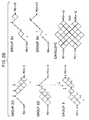
- Figure 2 shows an 8B/10B code with local parity and a short comma.
- Figure 3 shows an example of assigning "1s" and "0s" to the trellis diagram of Figure 2 to determine the bit sequence of the code characters.
-
- An invention described herein is directed to a method to correct a single erroneous byte in a frame. The fundamental principle is using a rectangular arrangement of horizontal and vertical parity bits, where the horizontal parity locates the erroneous byte and the vertical parity is used to correct it. The distinctive feature is that the functional equivalent of the horizontal parity is provided by a special 8B/10B transmission code with local parity.
- In a code with local parity, each 8-bit byte has a unique coded 10-bit byte which corresponds thereto. The coded bytes are designed such that if there is an error in any one of the bit locations, the valid coded byte would be converted into an invalid coded byte. Described herein below is a code having local parity.
- A set VPAR of 8 vertical parity bits is derived from the uncoded data, coded and packed into the first Idle word following the End of Frame. After identification of a faulty byte at the receiver, the VPAR bits are used to correct it.
- Initially, the elementary rectangular error correction scheme using parity bits is described. Then the use of horizontal parity to locate an error will be described. An improved version of an 8B/10B code with intrinsic local parity is presented. Then the correction of an erroneous byte by vertical parity bits is described as well as the restoration of faulty control characters.
- The basic correction scheme proposed according to the present invention is based on ordering of data and parity bits, as shown in Figure 1, in a rectangular or matrix arrangement. A frame is partitioned into small segments, preferably bytes or words. A parity or other means of error detection is attached to each of the segments, and together they form a matrix line. Successive segments are placed on the following lines. This first set of parity bits is called the horizontal parity. Several of these segments are followed by a vertical parity set as indicated in the matrix in Figure 1. The vertical parity consists of a parity bit for each data bit column. It is used to identify and correct the erroneous bit or bits in the segment which was tagged as erroneous by the horizontal parity.
- An entire faulty line can be corrected. For this reason, the vertical parity is computed on the uncoded bits, since error spread from decoding contained to a segment or byte does not interfere with correction. The vertical parity has enough bits to cover at least one segment. To correct longer error bursts, two or more vertical parity lines may be appended; by way of example, a first parity can be calculated from all the even numbered lines, and a second one from all the odd numbered lines. It is then possible to correct error bursts extending over a pair of adjacent lines, or two isolated shorter bursts, if one of them occurs in an even and the other in an odd numbered line. The vertical parity bits are coded like data. If an error occurs in a vertical parity byte, it is ignored and not used for correction of possible other errors.
- A necessary assumption is that, apart from short error bursts, the link error events occur randomly at a low enough rate so most of the time there is just a single error event within a frame. If this assumption does not hold, the frame length must be reduced, or a vertical parity must be inserted into the frame at fixed intervals. Another assumption is that most errors are confined to a single matrix line. The systems and methods shown described herein can be adapted to handle errors crossing line boundaries at the cost of increased complexity. It is a further requirement to have correct recognition of the start and the end of the frame in the presence of errors. A cyclic redundancy check computed over the frame ultimately determines the validity of the corrected or uncorrected frame. Retransmission facilities are preferably still available for the case where error correction fails: failure of the horizontal parity to detect certain multiple errors, an error burst longer than the vertical parity, lost byte synchronization, multiple error bursts, false start and end of frame detection, truncated or missing frames, etc.
- In the commonly used parity matrix, the horizontal parity is an explicit bit for each matrix line.
- In the example below, the horizontal parity is instead supplied by the transmission code all by itself. Transmission codes are subject to several constraints to enhance reliable low cost transmission. Additional constraints can be built into a code, so any odd number of errors in a byte or word generates an invalid word. Such a property of the code is referred to as 'local parity' [Martin, 1985]. For general applications, such codes are less desirable, because the added constraint makes it necessary to degrade some transmission parameters, and to accept a more complex and higher cost implementation. Other 8B/10B codes, including the Fibre Channel Standard (FCS) code, most times also indicate immediately an invalid byte when an error has occurred. However, a substantial ratio of errors generates only a disparity violation farther down the bit stream, away from the byte where the error has occurred, and so the byte which contains the error(s) cannot directly be identified. For the design of a binary, DC balanced code with local parity, the following options are available:
- It is possible to design codes consisting exclusively of balanced words, so any odd number of errors within such a word manifests itself as an unbalance. As an example, it is possible to convert 16 bits into 20 bits, such that all 20 bit words are balanced. However, such a 16B/20B code is complex to implement. Also, a single false bit can generate an error burst of 16 in the decoding process, which requires a larger set of vertical parity bits. Even though the 20 bit words are always balanced, the low frequency behavior of the code is no better than the partitioned 8B/10B FCS code.
- There exist low disparity 8B/10B codes with local parity, so an odd number of errors generates always an invalid code word. One such code was suggested by Martin [1985]. Codes of this type generally are more difficult to implement than the partitioned 8B/10B code[Widmer, 1983], and have stronger low frequency spectral components, so the time constants of high pass filters must be increased by over 40%. The code published by Martin [1985] also lacks a suitable comma confined to one byte. A code with a good comma is described below.
- For the 8B/10B transmission code described here, a built-in parity feature has been traded for increased low frequency content. Any 10B character of this code afflicted with an odd number of bit errors is an invalid character.
- The code below according to the present invention translates 8 source bits to 10 coded bits in an arrangement better suitable for serial transmission. It uses vectors from the set of 252 balanced (zero disparity) 10-bit vectors and from the 120 complementary vector pairs with a disparity of +/-4, which are inserted with alternating polarity. Thus, a single error in a character will generate a disparity of 2 or 6, which both are illegal combinations.
- The Run Length (RL), which is the number of contiguous identical bits, is limited to 5, and adjacent runs of 5 are not allowed. The bit pattern '11011111' and its complement are a synchronizing sequence or comma. It is embedded in a comma character '0110111110' or its complement '1001000001'. Serial transmission starts from the left. The comma character contains 4 inside transitions, and a sequence of comma characters generates 5 transitions per character. Beside the comma character, there are 4 other special, non-data characters.
- Alternatively, the bit sequence '11111011' and its complement can be chosen as a comma with compatible code vectors. The trellis diagrams below are then read from right to left rather than from left to right. The first bit of a transmitted code byte is then on the right hand side.
- All the valid coded characters are represented in the trellis diagrams of Figure 2, 'Trellis for 8B/10B Code with Local Parity', where each rising branch stands for a one bit, and each falling branch for a zero bit. For example,
Group 3K of Figure 2 which has one member, is reproduced in Figure 3. Figure 3 shows 11 nodes: 2, 4, 6, 8, 10, 12, 14, 16, 18, 20 and 22. The rising lines (or branches) 24, 26 and 28 represent 3 "ones". The following line orbranch 30 betweennodes 8 and 10 correspond to a zero. The risingbranches branches Group 3K is "1110111100". The numbers to the right of each node of Figure 2 stand for the number of different valid paths to that node from the input node. Each possible path through the trellis diagramm corresponds to one legitimate bit pattern. The disparity of a block of bits (such as a byte or character) is the algebraic difference between the number of ones minus the number of zeros. The running disparity RD at a particular point in the serial bit stream is the sum of the disparity of the preceding blocks. The disparity of a block of bits is equal to the difference between the RD at the end of the block and the RD at the beginning of the block. The digital sum variation is the algebraic difference between the maximum and minimum values of the RD over a block. At the boundary between bytes, the running disparity RD for the present code, is always +/-2. For 8B/10B codes without local parity, the RD at byte boundaries is usually +/-1. For the code described here, we limit the starting and ending RL to two, except that the coded bytes are allowed to start with 3 ones from RD= -2 or 3 zeros from RD = +2; coded bytes may end with 3 zeros at RD= - 2, and with 3 ones at RD= +2. The RL across character boundaries is thus limited to 5. The neighborhood of every possible RL of 5 is pruned so no misaligned comma sequences can arise. In Fig. 2, vectors passing through the isolated points marked x could all generate a false comma or a RL violation, including contiguous runs of 5. - The code comprises in the coded domain three major groups of vectors:
- The 174 disparity independent, balanced vectors
represented in
Group - The 27 balanced vectors of Group 2AC, 2D, and 2E are disparity dependent and can be entered only, if the starting RD is -2. For a positive starting RD, their complement is used.
- The 59 vectors in
Group Group 3F is the comma. - The Envelope contains all the vectors needed for the coding of 260 characters for a starting disparity of either +2 or -2. Not all the vectors of the envelope are actually permitted, but only those listed in the separate groupings listed above, which define all the constraints. There is a correlation between low frequency spectral components of a code and the traces through the trellis envelope. Beside the coarse characterization by the maximum Digital Sum Variation (DSV), a normalized offset can be defined, which is a measure of the area between the zero disparity line and a vector trace. The smaller the maximum offset, the better is the low frequency behavior. As seen from the envelope, the maximum DSV of this code is 10. It is possible to reduce the DSV to 8, but this entails contiguous runs of five. In this context, it is of interest that the upper and lower contours of the envelope do not represent valid characters. The only vectors through the highest and lowest point of the envelope are those of Group A/B. The outermost contours of the envelope are given by the outermost upper and lower contour of
Group 1 orGroup 1A/B. Starting with a disparity of +2, we can transmit 1101010100 or 1101100010, and in each case enclose an area between the contour and the zero disparity which amounts to 33 area units (disparity x time) per byte, or an average of 3.3 per bit interval, which we call the normalized offset. The complements of these same vectors starting with negative disparity follow the lower contour. Because the maximum offset for the vectors passing through the points with running disparity of +/-5 (point A and B ofGroup 1A/B) is no greater than the outermost vector limited to a DSV of 8, the low frequency penalty for the DSV of 10 is not as severe as one would otherwise expect for a DSV of 10 with no such added constraint. Simulations show that for this code the low frequency cutoff of a single RC high pass filter must be set no higher than 0.055% of the bit rate, if the eye closure is to be kept to less than 0.25 dB. This is lower than for the FCS code (U.S. Patent 4,486,739) by almost a factor of 2. For the variant of the code with a DSV of 8 but contiguous runs of 5, the low frequency cut-off can be moved up to 0.063% of the bit rate for an equal eye closure penalty. From Fig. 2, we can also easily see that the minimum transition density is 3 per character. - An implementation using full or partial tables is the easiest but probably the least economical approach, if the cost of the initial design effort is ignored. A design with reasonable complexity using just combinatorial logic can be achieved. Well over 200 vectors can be disposed off by using design principles similar to the FCS code: Change as few bits as possible and classify the vectors into groups to be handled by common hardware. For the last 30 or 40 vectors it becomes increasingly difficult to find commonalities, and to define groups with more than a few vectors. It is then mainly a question of when to resort to individual vector translation to complete the job. Because any implementation, other than by table lookup, is very dependent on the assignment of individual source bytes to a specific coded vector, we do not give a translation table. Any implementation with combinatorial logic will likely have at least two more levels of logic in the critical path, more gates, and generally larger fan-in numbers, when compared with the partitioned FCS code.
- Applications which do not require error correction are penalized by more complex implementations for the coder and decoder. In some instances, a somewhat faster technology may be required. All the high pass filters in the serial signal path need time constants larger by a factor of two. Otherwise, the performance of the code could be expected to be comparable to the FCS code. From the current perspective, an adoption of this code might be advantageous for the following types of links:
- Systems which always use forward error correction, not just as an option.
- Systems using forward error correction in combinations with very short frames or high error rates, which force short error correction blocks. For such cases, the ability to operate with just 8 vertical parity bits per block would be an advantage.
- As suggested by Martin [1985], a code with local parity could be exploited for maximum likelihood signal detection. For instance, if we use a single step offset in each direction from the perceived optimum sampling point for both time and amplitude, we could easily end up with 5 to 9 samples per bit or up to 90 samples per byte. For practical reasons, it is then important to recognize an erroneous byte right away, rather then at the end of the frame. Such a technique to reduce the error rate would also be preferable for real time and other delay sensitive systems.
- An odd parity bit is derived for each column of the coded or uncoded matrix, and transmitted in coded form after the end of the frame. For easy implementation, it is preferred to derive the parity from the uncoded data, because of better compatibility with common data formats, buffer width, and the processing stream. Typically, one byte of vertical parity bits will be generated, but a larger or smaller segmentation is possible. At the receiving end, the decoder may enlarge a single bit error to a burst of 8 in the decoded domain. The matrix correction scheme is not adversely affected by this error spread.
- For the code with local parity, a single bit transmission error will always generate an invalid byte. After the end of a frame has been received, each bit of the invalid byte in a column with a vertical parity violation is complemented. If more than one byte in a frame is invalid, no correction attempt is made.
- If a link is afflicted with a significant number of burst errors spread over less than 10 coded bits, one would want to be able to correct errors which straddle byte boundaries. To this end, two vertical parity bytes are sent along, the first is computed on all even numbered bytes, and the second on all odd numbered bytes.
- The case of special characters which are afflicted with errors deserves extra scrutiny. For applications which use a variety of special characters in unpredictable configurations, an additional vertical parity bit is used for the K bit, which indicates whether a byte is data or control information. For the FCS application, this bit would be useful only to correct errors in the comma character of the Start and End of Frame delimiter which can be done by other means.
- It is very important to correctly recognize the Start of Frame (SOF) and the End (EOF), otherwise the parity correction scheme does not work. At the transmitter, this is no problem, because of the absence of errors. Our goal is to recognize the frame boundaries at the receiver correctly, unless there are at least two bytes with errors. The companion application EP-A-0 709 979 "Apparatus and Method for Error Correction Based on Transmission Code Violations and Parity" includes a detailed description on how to reliably detect the FCS Start and End of Frame delimiters. A similar methodology can be used with the local parity code of this application. Only some details are different because the coded words, including the comma character are different.
- A code with local parity can locate an erroneous byte in a frame without extra parity bits, but such a code is more complex to implement and generates larger low frequency spectral components. This error locating techniques make error correction by simple vertical parity possible and is well suited for link architectures with short frames. It can be made transparent to transmission protocols above the link level.
- Martin W. Sachs. High Performance Networks, Technology and Protocols, Chapter II.5, Fibre Channel. Ahmed N. Tantawy, Editor. Kluwer Academic Publishers, Boston, 1994.
- X3T9 Technical Committee. Fibre Channel, Physical and Signaling Interface (FC-PH); Rev. 3.0. FC-P/92-001R3.0. American National Standards Institute, 1430 Broadway, New York, NY 10018, 1992. Available from: Global Engineering, 2805 McGaw St., Irvine, CA 92714
- Wayne D. Grover. Forward Error Correction in Dispersion-Limited Lightwave Systems. IEEE Journal of Lightwave Technology, 6(5):643-654, May 1988.
- C. Benz, M. Gowan and K. Springer. An Error Correcting Encoder and Decoder for a 1 Gbit/s Fiber Optic Link. Proc. IEEE 1991 Custom Integrated Circuits Conference, 7.1.1-7.1.4, San Diego, May 1991.
- D.H. McMahon, A.A. Kirby, B.A. Schofield and K. Springer. U.S. Pat. No. 5,144,304. Data and Forward Error Control Coding Techniques for Digital Signals. Sept. 1, 1992.
- K. Springer. A Forward Error Correcting Code for Gigabit Fiber Optic Links. Conference on High-Speed Fiber Networks and Channels (1991), Boston, September 1991. Proc. SPIE - Int. Soc. Opt. Eng. (USA), Vol. 1577, 1992, pp246-253.
- C.A. French. Distance Preserving Run-Length Limited Codes. IEEE Transactions on Magnetics, MAG-25(5):4093-4095, September 1989.
- M. Blaum. Combining ECC with modulation: performance comparisons. IEEE Transactions on Information Theory, 37(3):945-949, May 1991.
- M. Blaum, S. Litsyn, V. Buskens and C.A. van Tilborg. Error-Correcting Codes with Bounded Running Digital Sum. IEEE Transactions on Information Theory. 39(1):216-227, January 1993.
- C.S. Coetzee, H.C. Ferreira and P.G.W. van Rooyen. On the Performance and Implementation of a Class of Error and Erasure Control (d,k) Block Codes. IEEE Transactions on Magnetics, 26(5):2312-2314, September 1990.
- R.W. Hamming. Coding and Information Theory, 2nd Ed. Prentice Hall Inc., Englewood Cliffs, NJ 07632, 1986.
- G.N.N. Martin. A Rate 8/10 DC Balanced Code with Local Parity. IBM Technical Disclosure Bulletin, 27(9):5272-5279, February 1985.
- A. X. Widmer and P. A. Franaszek. A DC-Balanced, Partitioned-Block, 8B/10B Transmission Code. IBM Journal of Research and Development, Vol. 27, No. 5, pp.440-451, September 1983.
Claims (31)
- An apparatus for coding a frame of N-bit bytes into a frame of M-bit bytes wherein M > N > 0, and wherein said frame has a boundary and wherein there is a byte boundary between said bytes comprising:characterized by,means for providing a code containing members of M-bit bytes which is a subset of all possible M-bit bytes, for each of the 2N possible N-bit bytes there is a corresponding member in said subset,one of said members of said code is a comma used to identify said frame boundary and said byte boundary, said comma has a sequence of bits having a binary state selected from a first and second value such that said bit sequence of said comma is confined to said one of said members of said code and said bit sequence of said comma does not occur across a boundary between any combination of any other members of said code;means for assigning to each of said N-bit bytes in said frame said corresponding member from said code to form a coded frame corresponding to said frame;
means for storing said frame of N-bit bytes and
means for storing said coded frame;
whereby each of said members of said code has a sequence of bits, such that whenever a state of one of said bits is changed, a resulting M-bit byte is not one of said members of said code,
whereby N=8 and M=10, said code only permits run lengths of a binary state of less than or equal to 5, and said members of said code have a start and an end with a run length of one or two; a run of three at said start of a member is allowed only if the running disparity moves toward balance for the first 2 bits of the run; a run of three at the said end of a member is allowed only is the running disparity moves away from balance for the last 2 bits of the run. - An apparatus according to claim 1, further including a means for transmitting said coded frame to a receiving apparatus as a transmitted coded frame.
- An apparatus according to claim 2, wherein said receiving apparatus has a means for determining if said transmitted coded frame has an error.
- An apparatus according to claim 3, further including a means for correcting said error.
- An apparatus according to claim 1, wherein said code is a 10-bit code and wherein said code includes 10-bit bytes all of which have a digital sum variation of zero, +four, or -four.
- An apparatus according to claim 1, wherein said comma contains a bit pattern selected from the group consisting of '11011111' and its complement '00100000'.
- An apparatus according to claim 1, wherein said comma is embedded in '0110111110' and its complement '1001000001'.
- An apparatus according to claim 1, wherein said run length at said starting boundary of some of said members is 3 "1's" if the running disparity at said start is -2 and 3 "0's" if the running disparity is +2 at said start.
- An apparatus according to claim 1, wherein said run length at said end of some of said members is 3 zeros if the running disparity at said end is -2, and three ones if the running disparity is +2 at said end.
- An apparatus according to claim 1, wherein said code includes 174 10-bit bytes which are balanced and disparity independent, 27 pairs of balanced and disparity dependent 10-bit bytes, and 59 pairs of 10 bit bytes having disparity of ±4 and which are disparity dependent.
- An apparatus according to claim 1, wherein said means for storing said frame of N-bit bytes is a memory and wherein said means for storing said coded frame is a memory.
- An apparatus according to claim 3, further including a means for determining a bit location of said error.
- An apparatus according to claim 1, for producing a run length limited 8B/10B code for an unconstrained input data stream comprising:a means for storing a frame of a plurality of 8 bit bytes;a means for allocating to each of said 8-bit bytes a coded 10-bit byte to form a coded frame;a means for storing said coded frame;said set of coded 10-bit bytes comprises:a set of 162 balanced disparity independent coded bytes having digital sum variations of 4 or less having form:
11001 10100, 11001 10100, 10110 10100, 10101 10100, 10011 10100, 01110 10100, 11001 01100, 11001 01100, 10110 01100, 10101 01100, 10011 01100, 01110 01100, 11001 10010, 11001 10010, 10110 10010, 10101 10010, 10011 10010, 01110 10010, 11001 01010, 11001 01010, 10110 01010, 10101 01010, 10011 01010, 01110 01010, 11001 00110, 11001 00110, 10110 00110, 10101 00110, 10011 00110, 01110 00110, 11001 10001, 11001 10001, 10110 10001, 10101 10001, 10011 10001, 01110 10001, 11001 01001, 11001 01001, 10110 01001, 10101 01001, 10011 01001, 01110 01001, 11001 00101, 11001 00101, 10110 00101, 10101 00101, 10011 00101, 01110 00101, 11001 00011, 11001 00011, 10110 00011, 10101 00011, 10011 00011, 01110 00011, 01101 10100, 01011 10100, 00111 10100, 00101 01011, 00110 01011, 01001 01011, 01101 01100, 01011 01100, 00111 01100, 00101 10011, 00110 10011, 01001 10011, 01101 10010, 01011 10010, 00111 10010, 00101 01101, 00110 01101, 01001 01101, 01101 01010, 01011 01010, 00111 01010, 00101 10101, 00110 10101, 01001 10101, 01101 00110, 01011 00110, 00111 00110, 00101 11001, 00110 11001', 01001 11001, 01201 10001, 01011 10001, 00111 10001, 00101 01110, 00110 01110, 01001 01110, 01101 01001, 01011 01001, 00111 01001, 00101 10110, 00110 10110, 01001 10110, 01101 00101, 01011 00101, 00111 00101, 00101 11010, 00110 11010, 01001 11010, 01101 00011, 01011 00011, 00111 00011, 00101 11100, 00110 11100, 01001 11100, 01010 01011, 01100 01011, 10001 01011, 10010 01011, 10100 01011, 11000 01011, 01010 10011, 01100 10011, 10001 10011, 10010 10011, 10100 10011, 11000 10011, 01010 01101, 01100 01101, 10001 01101, 10010 01101, 10100 01101, 11000 01101, 01010 10101, 01100 10101, 10001 10101, 10010 10101, 10100 10101, 11000 10101, 01010 11001, 01100 11001, 10001 11001, 10010 11001, 10100 11001, 11000 11001, 01010 01110, 01100 01110, 10001 01110, 10010 01110, 10100 01110, 11000 01110, 01010 10110, 01100 10110, 10001 10110, 10010 10110, 10100 10110, 11000 10110, 01010 11010, 01100 11010, 10001 11010, 10010 11010, 10100 11010, 11000 11010, 01010 11100, 01100 11100, 10001 11100, 10010 11100, 10100 11100, 11000 11100, a set of 12 balanced disparity independent coded bytes, having a digital sum variation of 6 for the set having form:11011 00010, 11011 00001 00100 11101, 00100 11110, 10111 00010, 10111 00001 01000 11101, 01000 11110, 01111 00010, 01111 00001 10000 11101, 10000 11110, a set of 3 balanced disparity dependent 10-bit bytes which is used for a starting running disparity of -2, and for which the complement is used for a starting running disparity of +2: having form:11011 00100, 10111 00100, 01111 00100, a set of 11 balanced disparity independent 10-bit bytes which is used for a starting running disparity of -2, and for which the complement is used for a starting running disparity of +2 having form:11101 00100, 11100 10100, 11100 01100, 11100 00110, 11101 00010, 11100 10010, 11100 01010, 11100 00101, 11101 00001, 11100 10001, 11100 01001, a set of 13 balanced disparity dependent 10-bit bytes which is used for a starting running disparity of -2, and for which the complement is used for a starting running disparity of +2 having form:11101 01000, 11100 11000, 11001 11000, 11011 01000, 11010 11000, 10101 11000, 10111 01000, 10110 11000, 10011 11000, 01111 01000, 01110 11000, 01101 11000, 01011 11000, a set of 32 unbalanced disparity dependent 10-bit bytes with a disparity of +4 which is used for a starting running disparity of -2, and for which the complement is used for a starting running disparity of +2 having form:11101 01110, 10111 01110, 11100 11110, 10110 11110, 11101 01101, 10111 01101, 11100 11101, 10110 11101, 11101 01011, 10111 01011, 11100 11011, 10110 11011, 11101 00111, 10111 00111, 11100 10111, 10110 10111, 11011 01110, 01111 01110, 11010 11110, 01110 11110, 11011 01101, 01111 01101, 11010 11101, 01110 11101, 11011 01011, 01111 01011, 11010 11011, 01110 11011, 11011 00111, 01111 00111, 11010 10111, 01110 10111, a set of 9 unbalanced disparity dependent 10-bit bytes with a disparity of +4 which is used for a starting running disparity of -2, and for which the complement is used for a starting running disparity of +2 having form wherein the coded byte 01101 11110 represent the comma11001 11110, 10101 11110, 01101 11110, 11001 11101, 10101 11101, 01101 11101, 11001 11011, 10101 11011, 01101 11011, a set of 4 unbalanced disparity dependent 10-bit bytes with a disparity of +4 which is used for a starting running disparity of -2, and for which the complement is used for a starting running disparity of +2 having form:10011 11101, 01011 11101, 10011 11011, 01011 11011, a set of 9 unbalanced disparity dependent 10-bit bytes with a disparity of +4 which is used for a starting running disparity of -2, and for which the complement is used for a starting running disparity of +2 having form:11101 10110, 11011 10110; 10111 10110, 11101 10101, 11011 10101, 10111 10101, 11101 10011, 11011 10011, 10111 10011, a set of 5 unbalanced disparity dependent 10-bit bytes with a disparity of +4 which is used for a starting running disparity of -2, and for which the complement is used for a starting running disparity of +2having form:11101 11010, 11011 11010, 11101 11001, 11011 11001, 11101 11100. - An apparatus according to claim 12, wherein said means for storing said frame is a memory and said means for storing said coded frame is a memory.
- A method for coding a frame of N-bit bytes into a frame of coded M-bit bytes wherein M > N > 0 and wherein said frame has a frame boundary and wherein there is a byte boundary between said bytes, comprising the steps of:characterized by,providing a code containing members of M-bit bytes which is a subset of all possible M-bit bytes; for each of the 2N possible N-bit bytes there is a corresponding member in said subset, whereby one of said members of said code is a comma used to identify said frame boundary and said byte boundary, said comma has a sequence of bits having a binary state selected from a first and second value such that said bit sequence of said comma is confined to said one of said members of said code and said bit sequence of said comma does not occur across a boundary between any combination of any other members of said code,assigning to each of said N-bit bytes in said frame said corresponding member from said code to form a coded frame corresponding to said frame, and
storing said frame of N-bit bytes and
storing said coded frame,
whereby each of said members of said code has a sequence of bits such that whenever a state of one of said bits is changed, a resulting M-bit byte is not one of said members of said code,
whereby N=8 and M=10, said code only permits run lengths of a binary state of less than or equal to 5, and said members of said code have a start and an end with a run length of one or two; a run of three at said start of a member is allowed only if the running disparity moves toward balance for the first 2 bits of the run; a run of three at the said end of a member is allowed only if the running disparity moves away from balance for the last 2 bits of the run. - A method according to claim 15, further including the steps of transmitting said coded frame to a receiving apparatus as a transmitted coded frame.
- A method according to claim 16, wherein said receiving apparatus determines if said transmitted coded frame has an error.
- A method according to claim 17, further including correcting said error.
- A method according to claim 15, wherein said code is a 10-bit code and wherein said code includes all 10-bit bytes having a digital sum variation of 4 or less and a run length limit of 2 at each end.
- A method according to claim 15, wherein said comma contains a bit pattern selected from the group consisting of '11011111' and its complement '00100000'.
- A method according to claim 15, wherein said comma is selected from the group consisting of '0110111110' and its complement '1001000001'.
- A method according to claim 15, wherein said run length at said starting boundary of some of said members is 3 "1's" if the running disparity at said start is -2, and 3 "0's" if the running disparity is +2 at said start.
- A method according to claim 15, wherein said run length at said end of some of said members is 3 zeros if the running disparity at said end is -2, End three ones if the running disparity is +2 at said end.
- A method according to claim 15, wherein said code includes 174 10-bit bytes which are balanced and disparity independent, 27 pairs of balanced and disparity dependent 10-bit byes, and 59 complementary pairs of 10 bit bytes having disparity of ±4 and which are disparity dependent.
- A method according to claim 15, wherein said step of storing said frame of N-bit bytes is storing in a memory and wherein said step of storing said coded frame is storing in a memory.
- A method according to claim 17, further including the step of determining a bit location for said error.
- A method according to claim 15, for producing a run length limited 8B/10B code for an unconstrained input data sequence comprising:providing in a first memory location a frame of a plurality of 8 bit bytes;allocating to each of said 8-bit bytes a corresponding 10-bit byte;storing in a second memory location said corresponding coded 10-bit bytes as a coded frame;said frame of coded 10-bit bytes comprises:a set of 162 balanced disparity independent coded bytes having digital sum variation of 4 or less, having form:
11010 10100, 11001 10100, 10110 10100, 10101 10100, 10011 10100, 01110 10100, 11010 01100, 11001 01100, 10110 01100, 10101 01100, 10011 01100, 01110 01100, 11010 10010; 11001 10010, 10110 10010, 10101 10010, 10011 10010, 01110 10010, 11010 01010, 11001 01010, 10110 01010, 10101 01010, 10011 01010, 01110 01010, 11010 00110, 11001 00110, 10110 00110, 10101 00110, 10011 00110, 01110 00110, 11010 10001, 11001 10001, 10110 10001, 10101 10001, 10011 10001, 01110 10001, 11010 01001, 11001 01001, 10110 01001, 10101 01001, 10011 01001, 01110 01001, 11010 00101, 11001 00101, 10110 00101, 10101 00101, 10011 00101, 01110 00101, 11010 00011, 11001 00011, 10110 00011, 10101 00011, 10011 00011, 01110 00011, 01101 10100, 01011 10100, 00111 10100, 00101 01011, 00110 01011, 01001 01011, 01101 01100, 01011 01100, 00111 01100, 00101 10011, 00110 10011, 01001 10011, 01101 10010, 01011 10010, 00111 10010, 00101 01101, 00110 01101, 01001 01101, 01101 01010, 01011 01010, 00111 01010, 00101 10101, 00110 10101, 01001 10101, 01101 00110, 01011 00110, 00111 00110, 00101 11001, 00110 11001, 01001 11001, 01101 10001, 01011 10001, 00111 10001, 00101 01110, 00110 01110, 01001 01110, 01101 01001, 01011 01001, 00111 01001, 00101 10110, 00110 10110, 01001 10110, 01101 00101, 01011 00101, 00111 00101, 00101 11010, 00110 11010, 01001 11010, 01101 00011, 01011 00011, 00111 00011, 00101 11100, 00110 11100, 01001 11100, 01010 01011, 01100 01011, 10001 01011, 10010 01011, 10100 01011, 11000 01011, 01010 10011, 01100 10011, 10001 10011, 10010 10011, 10100 10011, 11000 10011, 01010 01101, 01100 01101, 10001 01101, 10010 01101, 10100 01101, 11000 01101, 01010 10101, 01100 10101, 10001 10101, 10010 10101, 10100 10101, 11000 10101, 01010 11001, 01100 11001, 10001 11001, 10010 11001, 10100 11001, 11000 11001, 01010 01110, 01100 01110, 10001 01110, 10010 01110, 10100 01110, 11000 01110, 01010 10110, 01100 10110, 10001 10110, 10010 10110, 10100 10110, 11000 10110, 01010 11010, 01100 11010, 10001 11010, 10010 11010, 10100 11010, 11000 11010, 01010 11100, 01100 11100, 10001 11100, 10010 11100, 10100 11100, 11000 11100, a set of 12 balanced disparity independent coded bytes having a digital sum variation of 6 for the set having form:11011 00010, 11011 00001, 00100 11101, 00100 11110, 10111 00010, 10111 00001, 01000 11101, 01000 11110, 01111 00010, 01111 00001, 10000 11101, 10000 11110, a set of 3 balanced disparity dependent 10-bit bytes which is used for a starting running disparity of -2, and for which the complement is used for a starting running disparity of +2 having form:11011 00100, 10111 00100, 01111 00100, a set of 11 balanced disparity dependent 10-bit bytes which is used for a starting running disparity of -2, and for which the complement is used for a starting running disparity of +2 having form:11101 00100; 11100 10100, 11100 01100, 11100 00110, 11101 00010, 11100 10010, 11100 01010, 11100 00101, 11101 00001, 11100 10001, 11100 01001, a set of 13 balanced disparity dependent 10-bit bytes which is used for a starting running disparity of -2, and for which the complement is used for a starting running disparity of +2 having form:11101 01000, 11100 11000, 11001 11000, 11011 01000, 11010 11000, 10101 11000, 10111 01000, 10110 11000, 10011 11000, 01111 01000, 01110 11000, 01101 11000, 01011 11000, a set of 32 unbalanced disparity dependent 10-bit bytes with a disparity of +4 which is used for a starting running disparity of -2, and for which the complement is used for a starting running disparity of +2 having form:11101 01110, 10111 01110, 11100 11110, 10110 11110, 11101 01101, 10111 01101, 11100 11101, 10110 11101, 11101 01011, 10111 01011, 11100 11011, 10110 11011, 11101 00111, 10111 00111, 11100 10111, 10110 10111, 11011 01110, 01111 01110, 11010 11110, 01110 11110, 11011 01101, 01111 01101, 11010 11101, 01110 11101, 11011 01011, 01111 01011, 11010 11011, 01110 11011, 11011 00111, 01111 00111, 11010 10111, 01110 10111, a set of 9 unbalanced disparity dependent 10-bit bytes with a disparity of +4, which is used for a starting running disparity of -2, and for which the complement is used for a starting running disparity of +2 having form wherein the comma is the byte 01101 11110:11001 11110, 10101 11110, 01101 11110, 11001 11101, 10101 11101, 01101 11101, 11001 11011, 10101 11011, 01101 11011, a set of 5 unbalanced disparity dependent 10-bit bytes with a disparity of +4 which is used for a starting running disparity of -2, and for which the complement is used for a starting running disparity of +2 having form:10011 11101, 01011 11101, 10011 11011, 01011 11011, a set of 9 unbalanced disparity dependent 10-bit bytes with a disparity of +4 which is used for a starting running disparity of -2, and for which the complement is used for a starting running disparity of +2 having form:11101 10110, 11011 10110, 10111 10110, 11101 10101, 11011 10101, 10111 10101, 11101 10011, 11011 10011, 10111 10011, a set of 4 unbalanced disparity dependent 10-bit bytes with a disparity of +4 which is used for a starting running disparity of -2, and for which the complement is used for a starting running disparity of +2 having form:11101 11010, 11011 11010, 11101 11001, 11011 11001, 11101 11100. - A method according to claim 26, wherein said step of storing said frame stores said frame in a memory and said step of storing said code frame stores said coded frame in a memory.
- An apparatus according to claim 13, wherein said comma contains a bit pattern selected from the group consisting of '11111011' and its complement '00000100'.
- An apparatus according to claims 13, wherein said comma is embedded in '0111110110' and its complement '1000001001'.
- An apparatus according to claim 16, which uses sets of coded words, which are the left/right symmetrical images of the code tables shown.
Applications Claiming Priority (2)
| Application Number | Priority Date | Filing Date | Title |
|---|---|---|---|
| US08/532,152 US5699062A (en) | 1995-02-01 | 1995-02-01 | Transmission code having local parity |
| US532152 | 1995-02-01 |
Publications (3)
| Publication Number | Publication Date |
|---|---|
| EP0725486A2 EP0725486A2 (en) | 1996-08-07 |
| EP0725486A3 EP0725486A3 (en) | 1998-05-20 |
| EP0725486B1 true EP0725486B1 (en) | 2004-07-14 |
Family
ID=24120571
Family Applications (1)
| Application Number | Title | Priority Date | Filing Date |
|---|---|---|---|
| EP96100861A Expired - Lifetime EP0725486B1 (en) | 1995-02-01 | 1996-01-23 | Transmission code having local parity |
Country Status (3)
| Country | Link |
|---|---|
| US (1) | US5699062A (en) |
| EP (1) | EP0725486B1 (en) |
| DE (1) | DE69632879T2 (en) |
Families Citing this family (24)
| Publication number | Priority date | Publication date | Assignee | Title |
|---|---|---|---|---|
| TW362305B (en) * | 1996-10-18 | 1999-06-21 | Koninkl Philips Electronics Nv | Apparatus and method for converting a sequence of m-bit information words into a modulated signal |
| WO1998023060A1 (en) * | 1996-11-22 | 1998-05-28 | Sony Corporation | Method and device for transmitting data |
| US5881074A (en) * | 1997-03-25 | 1999-03-09 | Level One Communications, Inc. | 1000base-t packetized trellis coder |
| US5835036A (en) * | 1997-05-12 | 1998-11-10 | Cisco Systems Co. | Method of encoding data for transmission |
| US6088827A (en) * | 1997-08-28 | 2000-07-11 | Level One Communications, Inc. | 1000BASE-T packetized trellis coder |
| US6226269B1 (en) * | 1998-05-01 | 2001-05-01 | Emulex Corporation | Elimination of invalid data in loop network |
| US6438728B1 (en) * | 1999-12-15 | 2002-08-20 | Intel Corporation | Error character generation |
| KR100384886B1 (en) * | 2000-10-10 | 2003-05-22 | 주식회사 케이티 | Apparatus and Method for Using Nibble Inversion Code |
| FR2817683B1 (en) * | 2000-12-05 | 2003-01-31 | Bull Sa | METHOD FOR CODING / DECODING DIGITAL DATA TRANSMITTED ON A SERIAL LINK, ESPECIALLY OF THE TYPE SAID "8B / 10B", AND IMPLEMENTING DEVICE |
| AU2002305315A1 (en) * | 2001-05-08 | 2002-11-18 | International Business Machines Corporation | 8b/10b encoding and decoding for high speed applications |
| US7389463B2 (en) * | 2001-05-29 | 2008-06-17 | Thomson Licensing | Hierarchical block coding for a packet-based communications system |
| US6920604B2 (en) * | 2002-04-08 | 2005-07-19 | Galazar Networks, Inc. | Systems and methods for high speed serial encoding and decoding for data and control interfaces |
| KR101129348B1 (en) * | 2002-06-21 | 2012-03-27 | 톰슨 라이센싱 | Method of forward error correction |
| FR2861517B1 (en) * | 2003-10-23 | 2006-01-27 | Thomson Licensing Sa | METHOD OF RECONSTRUCTING LOST PACKETS AND APPARATUSES IMPLEMENTING THE METHOD |
| US6876315B1 (en) | 2004-03-12 | 2005-04-05 | International Business Machines Corporation | DC-balanced 6B/8B transmission code with local parity |
| US6914545B1 (en) * | 2004-10-13 | 2005-07-05 | Seiko Epson Corporation | Circuitry and methods for reducing run-length of encoded data |
| US7292161B2 (en) * | 2005-05-31 | 2007-11-06 | International Business Machines Corporation | NB/MB coding apparatus and method using both disparity independent and disparity dependent encoded vectors |
| US7158057B1 (en) | 2005-09-07 | 2007-01-02 | Seiko Epson Corporation | Circuitry and methods for high speed data encoding |
| US7405679B1 (en) | 2007-01-30 | 2008-07-29 | International Business Machines Corporation | Techniques for 9B10B and 7B8B coding and decoding |
| US9407394B2 (en) * | 2014-02-03 | 2016-08-02 | Valens Semiconductor Ltd. | Frequent flow control by replacing certain idle words with bitwise complement words |
| US9887707B2 (en) * | 2016-06-30 | 2018-02-06 | Mapper Lithography Ip B.V. | Method and device for generating a decoded and synchronized output |
| CN106776394B (en) * | 2017-01-11 | 2019-05-14 | 深圳大普微电子科技有限公司 | A kind of hardware system and memory of data conversion |
| CN114208041A (en) * | 2019-08-30 | 2022-03-18 | 索尼半导体解决方案公司 | Encoding device, encoding method, decoding device, decoding method, and program |
| US20230308210A1 (en) * | 2019-08-30 | 2023-09-28 | Sony Semiconductor Solutions Corporation | Encoding device, encoding method, decoding device, decoding method, and program |
Family Cites Families (10)
| Publication number | Priority date | Publication date | Assignee | Title |
|---|---|---|---|---|
| US4365332A (en) * | 1980-11-03 | 1982-12-21 | Fairchild Camera And Instrument Corp. | Method and circuitry for correcting errors in recirculating memories |
| US4464747A (en) * | 1982-02-18 | 1984-08-07 | The Singer Company | High reliability memory |
| US4486739A (en) * | 1982-06-30 | 1984-12-04 | International Business Machines Corporation | Byte oriented DC balanced (0,4) 8B/10B partitioned block transmission code |
| NL8402445A (en) * | 1984-01-20 | 1985-08-16 | Philips Nv | METHOD FOR CODING N-BITS INFORMATION WORDS TO M-BITS CODEWORDS, DEVICE FOR PERFORMING THAT METHOD, METHOD FOR DECODING M-BITS CODE-WORDS, AND DEVICE FOR PERFORMING THAT METHOD |
| EP0178813B1 (en) * | 1984-10-01 | 1993-08-18 | Matsushita Electric Industrial Co., Ltd. | Method and apparatus for encoding binary data |
| JPS63257836A (en) * | 1987-04-16 | 1988-10-25 | Man Design Kk | Data transmission system |
| WO1992009162A1 (en) * | 1990-11-13 | 1992-05-29 | Hewlett-Packard Company | Dc-free line code and bit and frame synchronization for arbitrary data transmission |
| GB8912471D0 (en) * | 1989-05-31 | 1989-07-19 | Int Computers Ltd | Data transmission code |
| US5144304A (en) * | 1989-07-17 | 1992-09-01 | Digital Equipment Corporation | Data and forward error control coding techniques for digital signals |
| JP3083011B2 (en) * | 1992-12-28 | 2000-09-04 | キヤノン株式会社 | Data recording method and device |
-
1995
- 1995-02-01 US US08/532,152 patent/US5699062A/en not_active Expired - Fee Related
-
1996
- 1996-01-23 EP EP96100861A patent/EP0725486B1/en not_active Expired - Lifetime
- 1996-01-23 DE DE69632879T patent/DE69632879T2/en not_active Expired - Lifetime
Non-Patent Citations (2)
| Title |
|---|
| FERREIRA H.C. ET AL: "Hamming Distance Preserving Mappings and Trellis Codes with Constrained Binary Symbols", IEEE TRANSACTIONS ON INFORMATION THEORY, vol. 35, no. 5, September 1989 (1989-09-01), pages 1009 - 1103, XP000100947, DOI: doi:10.1109/18.42229 * |
| SCHOUHAMMER; IMMINK; BEENKER: "Binary Transmission Codes with Higher Order Spectral Zeroes at Zero Frequency", IEEE TRANSACTIONS ON INFORMATION THEORY, vol. IT-33, no. 3, May 1987 (1987-05-01), pages 452 - 454, XP002218921 * |
Also Published As
| Publication number | Publication date |
|---|---|
| EP0725486A3 (en) | 1998-05-20 |
| US5699062A (en) | 1997-12-16 |
| DE69632879T2 (en) | 2005-08-25 |
| DE69632879D1 (en) | 2004-08-19 |
| EP0725486A2 (en) | 1996-08-07 |
Similar Documents
| Publication | Publication Date | Title |
|---|---|---|
| EP0725486B1 (en) | Transmission code having local parity | |
| US6198413B1 (en) | Partitioned DC balanced (0,6) 16B/18B transmission code with error correction | |
| US5784387A (en) | Method for detecting start-of-frame, end of frame and idle words in a data stream | |
| EP0097763B1 (en) | A method and apparatus for producing a dc balanced (0,4) run length limited rate 8b/10b code from an input data stream | |
| US6195764B1 (en) | Data encoder/decoder for a high speed serial link | |
| US3810111A (en) | Data coding with stable base line for recording and transmitting binary data | |
| Widmer et al. | A DC-balanced, partitioned-block, 8B/10B transmission code | |
| EP0352970B1 (en) | System and method for detecting character boundaries in a serial coded data stream | |
| US5396239A (en) | Data and forward error control coding techniques for digital signals | |
| EP0471130B1 (en) | Coding method and apparatus for pipelined and parallel processing | |
| US6504493B1 (en) | Method and apparatus for encoding/decoding data | |
| US6333704B1 (en) | Coding/decoding system of bit insertion/manipulation line code for high-speed optical transmission system | |
| EP0344903A2 (en) | Traversed (d, k) code translation | |
| JPH06119197A (en) | Device and method for error detection and reduction of simultaneous switching noise | |
| MXPA96006099A (en) | Method of digital data transmission | |
| US20090276683A1 (en) | Data transmission equipment and generating method for transmission code | |
| US7205911B2 (en) | Apparatus and method for 8B/10B code-group validity check | |
| US20030217320A1 (en) | Cyclic redundancy check circuit for use with self-synchronous scramblers | |
| US6617985B1 (en) | Method and/or apparatus for implementing constraint codes with low error propagation | |
| US5878061A (en) | Providing serial data clock signal transitions with parity bits | |
| US5938773A (en) | Sideband signaling with parity bit schemes | |
| JP2000149457A (en) | Modulation device and method therefor, demodulation device and method therefor, and distribution medium | |
| JP3014309B2 (en) | Coding device and method | |
| US20230163941A1 (en) | System and method for transition encoding with flexible word-size | |
| JPS59183559A (en) | Digital transmitter |
Legal Events
| Date | Code | Title | Description |
|---|---|---|---|
| PUAI | Public reference made under article 153(3) epc to a published international application that has entered the european phase |
Free format text: ORIGINAL CODE: 0009012 |
|
| AK | Designated contracting states |
Kind code of ref document: A2 Designated state(s): DE FR GB |
|
| 17P | Request for examination filed |
Effective date: 19970120 |
|
| PUAL | Search report despatched |
Free format text: ORIGINAL CODE: 0009013 |
|
| AK | Designated contracting states |
Kind code of ref document: A3 Designated state(s): DE FR GB |
|
| 17Q | First examination report despatched |
Effective date: 20020402 |
|
| GRAP | Despatch of communication of intention to grant a patent |
Free format text: ORIGINAL CODE: EPIDOSNIGR1 |
|
| GRAS | Grant fee paid |
Free format text: ORIGINAL CODE: EPIDOSNIGR3 |
|
| GRAA | (expected) grant |
Free format text: ORIGINAL CODE: 0009210 |
|
| AK | Designated contracting states |
Kind code of ref document: B1 Designated state(s): DE FR GB |
|
| REG | Reference to a national code |
Ref country code: GB Ref legal event code: FG4D |
|
| REF | Corresponds to: |
Ref document number: 69632879 Country of ref document: DE Date of ref document: 20040819 Kind code of ref document: P |
|
| ET | Fr: translation filed | ||
| PLBE | No opposition filed within time limit |
Free format text: ORIGINAL CODE: 0009261 |
|
| STAA | Information on the status of an ep patent application or granted ep patent |
Free format text: STATUS: NO OPPOSITION FILED WITHIN TIME LIMIT |
|
| 26N | No opposition filed |
Effective date: 20050415 |
|
| REG | Reference to a national code |
Ref country code: GB Ref legal event code: 746 Effective date: 20071206 |
|
| PGFP | Annual fee paid to national office [announced via postgrant information from national office to epo] |
Ref country code: FR Payment date: 20110120 Year of fee payment: 16 |
|
| REG | Reference to a national code |
Ref country code: FR Ref legal event code: ST Effective date: 20120928 |
|
| PG25 | Lapsed in a contracting state [announced via postgrant information from national office to epo] |
Ref country code: FR Free format text: LAPSE BECAUSE OF NON-PAYMENT OF DUE FEES Effective date: 20120131 |
|
| PGFP | Annual fee paid to national office [announced via postgrant information from national office to epo] |
Ref country code: DE Payment date: 20150129 Year of fee payment: 20 |
|
| PGFP | Annual fee paid to national office [announced via postgrant information from national office to epo] |
Ref country code: GB Payment date: 20150127 Year of fee payment: 20 |
|
| REG | Reference to a national code |
Ref country code: DE Ref legal event code: R071 Ref document number: 69632879 Country of ref document: DE |
|
| REG | Reference to a national code |
Ref country code: GB Ref legal event code: PE20 Expiry date: 20160122 |
|
| PG25 | Lapsed in a contracting state [announced via postgrant information from national office to epo] |
Ref country code: GB Free format text: LAPSE BECAUSE OF EXPIRATION OF PROTECTION Effective date: 20160122 |