EP0726514B1 - Methods for using non contiguously reserved storage space for data migration in a redundant hierarchic data storage system - Google Patents
Methods for using non contiguously reserved storage space for data migration in a redundant hierarchic data storage system Download PDFInfo
- Publication number
- EP0726514B1 EP0726514B1 EP95112454A EP95112454A EP0726514B1 EP 0726514 B1 EP0726514 B1 EP 0726514B1 EP 95112454 A EP95112454 A EP 95112454A EP 95112454 A EP95112454 A EP 95112454A EP 0726514 B1 EP0726514 B1 EP 0726514B1
- Authority
- EP
- European Patent Office
- Prior art keywords
- raid
- data
- mirror
- storage space
- unused
- Prior art date
- Legal status (The legal status is an assumption and is not a legal conclusion. Google has not performed a legal analysis and makes no representation as to the accuracy of the status listed.)
- Expired - Lifetime
Links
Images


Classifications
-
- G—PHYSICS
- G11—INFORMATION STORAGE
- G11C—STATIC STORES
- G11C29/00—Checking stores for correct operation ; Subsequent repair; Testing stores during standby or offline operation
- G11C29/70—Masking faults in memories by using spares or by reconfiguring
- G11C29/74—Masking faults in memories by using spares or by reconfiguring using duplex memories, i.e. using dual copies
-
- G—PHYSICS
- G06—COMPUTING; CALCULATING OR COUNTING
- G06F—ELECTRIC DIGITAL DATA PROCESSING
- G06F11/00—Error detection; Error correction; Monitoring
- G06F11/07—Responding to the occurrence of a fault, e.g. fault tolerance
- G06F11/08—Error detection or correction by redundancy in data representation, e.g. by using checking codes
- G06F11/10—Adding special bits or symbols to the coded information, e.g. parity check, casting out 9's or 11's
- G06F11/1076—Parity data used in redundant arrays of independent storages, e.g. in RAID systems
-
- G—PHYSICS
- G06—COMPUTING; CALCULATING OR COUNTING
- G06F—ELECTRIC DIGITAL DATA PROCESSING
- G06F3/00—Input arrangements for transferring data to be processed into a form capable of being handled by the computer; Output arrangements for transferring data from processing unit to output unit, e.g. interface arrangements
- G06F3/06—Digital input from, or digital output to, record carriers, e.g. RAID, emulated record carriers or networked record carriers
- G06F3/0601—Interfaces specially adapted for storage systems
- G06F3/0602—Interfaces specially adapted for storage systems specifically adapted to achieve a particular effect
- G06F3/061—Improving I/O performance
-
- G—PHYSICS
- G06—COMPUTING; CALCULATING OR COUNTING
- G06F—ELECTRIC DIGITAL DATA PROCESSING
- G06F3/00—Input arrangements for transferring data to be processed into a form capable of being handled by the computer; Output arrangements for transferring data from processing unit to output unit, e.g. interface arrangements
- G06F3/06—Digital input from, or digital output to, record carriers, e.g. RAID, emulated record carriers or networked record carriers
- G06F3/0601—Interfaces specially adapted for storage systems
- G06F3/0602—Interfaces specially adapted for storage systems specifically adapted to achieve a particular effect
- G06F3/0614—Improving the reliability of storage systems
-
- G—PHYSICS
- G06—COMPUTING; CALCULATING OR COUNTING
- G06F—ELECTRIC DIGITAL DATA PROCESSING
- G06F3/00—Input arrangements for transferring data to be processed into a form capable of being handled by the computer; Output arrangements for transferring data from processing unit to output unit, e.g. interface arrangements
- G06F3/06—Digital input from, or digital output to, record carriers, e.g. RAID, emulated record carriers or networked record carriers
- G06F3/0601—Interfaces specially adapted for storage systems
- G06F3/0628—Interfaces specially adapted for storage systems making use of a particular technique
- G06F3/0646—Horizontal data movement in storage systems, i.e. moving data in between storage devices or systems
- G06F3/0647—Migration mechanisms
-
- G—PHYSICS
- G06—COMPUTING; CALCULATING OR COUNTING
- G06F—ELECTRIC DIGITAL DATA PROCESSING
- G06F3/00—Input arrangements for transferring data to be processed into a form capable of being handled by the computer; Output arrangements for transferring data from processing unit to output unit, e.g. interface arrangements
- G06F3/06—Digital input from, or digital output to, record carriers, e.g. RAID, emulated record carriers or networked record carriers
- G06F3/0601—Interfaces specially adapted for storage systems
- G06F3/0668—Interfaces specially adapted for storage systems adopting a particular infrastructure
- G06F3/0671—In-line storage system
- G06F3/0683—Plurality of storage devices
- G06F3/0689—Disk arrays, e.g. RAID, JBOD
-
- G—PHYSICS
- G11—INFORMATION STORAGE
- G11B—INFORMATION STORAGE BASED ON RELATIVE MOVEMENT BETWEEN RECORD CARRIER AND TRANSDUCER
- G11B20/00—Signal processing not specific to the method of recording or reproducing; Circuits therefor
- G11B20/10—Digital recording or reproducing
- G11B20/18—Error detection or correction; Testing, e.g. of drop-outs
- G11B20/1803—Error detection or correction; Testing, e.g. of drop-outs by redundancy in data representation
-
- G—PHYSICS
- G06—COMPUTING; CALCULATING OR COUNTING
- G06F—ELECTRIC DIGITAL DATA PROCESSING
- G06F3/00—Input arrangements for transferring data to be processed into a form capable of being handled by the computer; Output arrangements for transferring data from processing unit to output unit, e.g. interface arrangements
- G06F3/06—Digital input from, or digital output to, record carriers, e.g. RAID, emulated record carriers or networked record carriers
- G06F3/0601—Interfaces specially adapted for storage systems
- G06F3/0668—Interfaces specially adapted for storage systems adopting a particular infrastructure
- G06F3/0671—In-line storage system
- G06F3/0673—Single storage device
Definitions
- This invention relates to data storage systems, such as a hierarchic disk array data storage systems, and methods for using reserved storage space for data migration within such systems.
- Disk array data storage system have multiple storage disk drive devices which are arranged and coordinated to form a single mass storage system.
- Availability is the ability to access data stored in the storage system and the ability to insure continued operation in the event of some failure. Typically, data availability is provided through the use of redundancy wherein data, or relationships among data, are stored in multiple locations.
- mirror data is duplicated and stored in two separate areas of the storage system. For example, in a disk array, the identical data is provided on two separate disks in the disk array.
- the mirror method has the advantages of high performance and high data availability due to the duplex storing technique.
- the mirror method is also relatively expensive as it effectively doubles the cost of storing data.
- the second or "parity" method a portion of the storage area is used to store redundant data, but the size of the redundant storage area is less than the remaining storage space used to store the original data. For example, in a disk array having five disks, four disks might be used to store data with the fifth disk being dedicated to storing redundant data.
- the parity method is advantageous because it is less costly than the mirror method, but it also has lower performance and availability characteristics in comparison to the mirror method.
- US 5,166,939 describes a data storage apparatus.
- the data storage apparatus is made up of a plurality of physical storage devices.
- the user has the opportunity to change the configuration of the physical address space with respect to its division into redundancy groups.
- the parallel array of drives has a logical unit address space comprising two application logical units.
- Each logical unit is configured to include addressable logical blocks.
- To each of the logical blocks of the logical units corresponds a data block in a data group at the space, the data blocks of a logical unit being logically contiguously arranged.
- the data group at the space also includes additional data groups reserved for dynamic configuration, i.e., these data groups can be formatted on the disk drives of the parallel array at initialisation or at any time during the run time of the parallel array, but are not available to the application software in the initial configuration of the parallel array.
- the redundancy group configuration of the parallel array is illustrated by the two-dimensional address space, comprising the entire memory space of the parallel array. When reconfigurating the address space, this is done by formatting the physical drives of the parallel array.
- hybrid redundancy direct-access storage device array with design options IBM Technical Disclosure Bulletin, vol. 47, No. 02 B, February 19, 1994, pages 141 to 148, a hybrid DASD array is described, wherein each DASD comprising the array is fixedly divided into three areas, a D-area containing the user data, a C-area containing the check sum, and a M-area containing the staged mirrored data distained for the D-area.
- User addressable data is mapped to the check sum domain to provide any desired RAID type of check-sum array.
- a non-volatile RAM is used in order to provide an address map of addresses diverted from the check-sum domain to the mirror domain. After the data residing in the M-areas satisfies selected staging criteria, it is written to the check-sum areas and deleted from the M-areas.
- the data storage system includes a disk array having a plurality of storage disks and a disk array controller which coordinates data transfer to and from the disks.
- the storage disks define a physical storage space.
- the data storage system also includes a RAID management system operatively coupled to the disk array controller for mapping two virtual storage spaces onto the physical storage space of the storage disks.
- the first or RAID-level virtual storage space presents the physical storage space as multiple mirror and parity RAID areas.
- the mirror RAID areas contain mirror allocation blocks that store data according to RAID Level 1 (mirror redundancy) and the parity RAID areas contain parity allocation blocks that store data according to RAID Level 5 (parity redundancy).
- the second or application-level virtual storage space presents the physical storage space as multiple virtual blocks.
- the RAID management system migrates data between the mirror and parity allocation blocks so the data undergoes a change in redundancy between RAID Level 1 (i.e., mirror redundancy) and RAID Level 5 (i.e., parity redundancy) in a manner which optimizes performance and reliability.
- the RAID management system reserves an amount of unused storage space within the RAID-level virtual storage space to temporarily which can be the target of data moves during the migration.
- the unused storage space is preferably equivalent in size to one RAID area. However, the unused storage space is not in any one RAID area or any one physical location, but can be allowed to distribute over various RAID areas in a non-contiguous manner across the storage disks.
- the RAID management system employs the non-contiguous unused space to assist in creating mirror allocation blocks.
- the method includes several possible techniques that make use of the unused storage space. The techniques are sequentially tried until at least one mirror allocation block is created.
- the first technique is to locate an unused RAID area and convert it to a mirror RAID area containing at least one usable mirror allocation block.
- the second technique is to gather the empty parity allocation blocks into an unused RAID area which can be converted to a mirror RAID area containing at least one usable mirror allocation block.
- the third technique is to alternately perform the following steps (a) and (b) until an unused RAID area is created, and to then perform step (c): (a) migrate data from mirror allocation blocks to parity allocation blocks to empty the mirror allocation block; (b) gather the empty mirror allocation blocks into an unused RAID area; and (c) convert the unused RAID area into a parity RAID area.
- the steps (a)-(c) of the third technique are repeated until an unused RAID area is created that can be converted into a mirror RAID area without violating the minimum reserved amount of unused storage space.
- the RAID management system empties an entire RAID area for use in sizable data movement operation, such as rebuild tasks, adding new storage disks, and the like.
- the RAID management system first locates a RAID area (mirror or parity) that is only partially filled with data. The data is then moved from the RAID area to unused storage space. This leaves the RAID area empty and ready for conversion to a mirror or parity RAID area.
- Fig. 1 shows a data storage system 10 constructed according to this invention.
- data storage system 10 is a disk array data storage system which includes a hierarchic disk array 11 having a plurality of storage disks 12, a disk array controller 14 coupled to the disk array 11 to coordinate data transfer to and from the storage disks 12, and a RAID management system 16.
- a “disk” is any non-volatile, randomly accessible, rewritable mass storage device which has the ability of detecting its own storage failures. It includes both rotating magnetic and optical disks and solid-state disks, or non-volatile electronic storage elements (such as PROMs, EPROMs, and EEPROMs).
- the term “disk array” is a collection of disks, the hardware required to connect them to one or more host computers, and management software used to control the operation of the physical disks and present them as one or more virtual disks to the host operating environment.
- a “virtual disk” is an abstract entity realized in the disk array by the management software.
- RAID Redundant Array of Independent Disks
- the term "RAID” means a disk array in which part of the physical storage capacity is used to store redundant information about user data stored on the remainder of the storage capacity. The redundant information enables regeneration of user data in the event that one of the array's member disks or the access path to it fails.
- Disk array controller 14 is coupled to disk array 11 via one or more interface buses 13, such as a small computer system interface (SCSI).
- RAID management system 16 is operatively coupled to disk array controller 14 via an interface protocol 15.
- Data memory system 10 is also coupled to a host computer (not shown) via an I/O interface bus 17.
- RAID management system 16 can be embodied as a separate component, or configured within disk array controller 14 or within the host computer to provide a data manager means for controlling disk storage and reliability levels, and for transferring data among various reliability storage levels. These reliability storage levels are preferably mirror or parity redundancy levels as described below, but can also include a reliability storage level with no redundancy at all.
- the disk array controller 14 is preferably implemented as a dual controller consisting of disk array controller A 14a and disk array controller B 14b. Dual controllers 14a and 14b enhance reliability by providing continuous backup and redundancy in the event that one controller becomes inoperable. This invention can be practiced, however, with a single controller or other architectures.
- the hierarchic disk array 11 can be characterized as different storage spaces, including its physical storage space and one or more virtual storage spaces. These various views of storage are related through mapping techniques. For example, the physical storage space of the disk array can be mapped into a virtual storage space which delineates storage areas according to the various data reliability levels. Some areas within the virtual storage space can be allocated for a first reliability storage level, such as mirror or RAID level 1, and other areas can be allocated for a second reliability storage level, such as parity or RAID level 5. The various mapping techniques and virtual spaces concerning RAID levels are described below in more detail.
- Data storage system 10 includes a memory map store 21 that provides for persistent storage of the virtual mapping information used to map different storage spaces onto one another.
- the memory map store is external to the disk array, and preferably resident in the disk array controller 14.
- the memory mapping information can be continually or periodically updated by the controller or RAID management system as the various mapping configurations among the different views change.
- the memory map store 21 is embodied as two non-volatile RAMs (Random Access Memory) 21 a and 21 b which are located in respective controllers 14a and 14b.
- An example non-volatile RAM (NVRAM) is a battery-backed RAM.
- a battery-backed RAM uses energy from an independent battery source to maintain the data in the memory for a period of time in the event of power loss to the data storage system 10.
- One preferred construction is a self-refreshing, battery-backed DRAM (Dynamic RAM).
- the dual NVRAMs 21 a and 21 b provide for redundant storage of the memory mapping information.
- the virtual mapping information is duplicated and stored in both NVRAMs 21 a and 21 b according to mirror redundancy techniques.
- NVRAM 21 a can be dedicated to storing the original mapping information
- NVRAM 21b can be dedicated to storing the redundant mapping information.
- a mirrored memory map store can be configured using a single non-volatile RAM with sufficient space to store the data in duplicate.
- disk array 11 has multiple storage disk drive devices 12. Example sizes of these storage disks are one to three Gigabytes.
- the storage disks can be independently connected or disconnected to mechanical bays that provide interfacing with SCSI bus 13.
- the data storage system is designed with twelve active mechanical bays. Four SCSI buses are used to interface these bays with disk array controller 14 (i.e., one bus per three mechanical bays). If the active bays are fully loaded, the data storage system has an example combined capacity of 12-36 Gigabytes.
- Disk array controller 14 recognizes storage disks 12 regardless into which bay they are plugged.
- the data storage system 10 is designed to permit "hot plug" of additional disks into available mechanical bays in the disk array while the disk array is in operation.
- the storage disks 12 in disk array 11 can be conceptualized, for purposes of explanation, as being arranged in a mirror group 18 of multiple disks 20 and a parity group 22 of multiple disks 24.
- Mirror group 18 represents a first memory location or RAID area of the disk array which stores data according to a first or mirror redundancy level. This mirror redundancy level is also considered a RAID Level 1.
- RAID Level 1 or disk mirroring, offers the highest data reliability by providing one-to-one protection in that every bit of data is duplicated and stored within the data storage system.
- the mirror redundancy is diagrammatically represented by the three pairs of disks 20 in Fig. 1.
- Original data can be stored on a first set of disks 26 while duplicative, redundant data is stored on the paired second set of disks 28.
- Fig. 2 illustrates the storage of data according to RAID Level 1 in more detail.
- the vertical columns represent individual disks, of which disks 0, 1, 2, and 3 are illustrated.
- the physical storage space contained in this disk array of four disks can be configured into multiple stripes, as represented by the horizontal rows.
- a "stripe" extends across the storage disks and is comprised of numerous, equal sized segments of storage space where one segment is associated with each disk in the array. That is, a segment is the portion of a stripe that resides on a single disk. Each stripe holds a predetermined amount of data which is distributed across the storage disks. Some segments of a stripe are used for original data while other segments are used for redundant data.
- the parity group 22 of disks 24 represent a second memory location or RAID area in which data is stored according to a second redundancy level, such as RAID Level 5.
- RAID Level 5 a second redundancy level
- Fig. 3 shows a parity RAID area layout in more detail. Similar to the mirror RAID area layout of Fig. 2, the physical storage space of disks 0, 1, 2, 3 can be configured into multiple equal sized stripes.
- data is stored according to RAID Level 5 and the redundant data stored in the segments is referenced by letter P.
- the redundant P segments store the parity of the other segments in the stripe.
- the redundant P segment on disk 3 stores the parity of disks 0, 1, and 2.
- the parity for each stripe is computed by some function, such as an exclusive OR function which is represented by the symbol ". ".
- disks 12 are configured to contain plural, equal sized storage regions (referenced as numeral 35 in Fig. 4), wherein individual regions have multiple segments. The regions are grouped together to form RAID areas in one virtual view of the storage space. Additionally, another (host-defined) view of storage space is presented to the user or host so that the RAID areas and data redundancy storing techniques are transparent to the user or host.
- Data storage system 10 manages the "migration" of data between mirror and parity storage schemes.
- the management of both types of redundancy is coordinated by RAID management system 16 (Fig. 1).
- RAID management system 16 manages the two different types of RAID areas in the disk array as a memory hierarchy with the mirror RAID areas acting similar to a cache for the parity RAID areas.
- RAID management system 16 shifts, organizes, and otherwise manages the data between the mirror and parity RAID areas in accordance with a defined performance protocol.
- the process of moving data between the mirror and parity RAID areas is referred to as "migration".
- the performance protocols implemented by RAID management system 16 includes one of two preferred migration policies.
- the first migration policy known as "access frequency”
- the most frequently accessed data on the hierarchic disk array is maintained in the mirror RAID area 18.
- Less frequently accessed data is maintained in the parity RAID area 22.
- access recency the most recently accessed data is maintained in the mirror RAID area 18 while the less recently accessed data is stored in parity RAID area 22.
- Other performance protocols may be employed. Ideally, such protocols are defined based upon the specific computer application and the needs of the user.
- the RAID management system 16 automatically "tunes" the storage resources of a data storage system according to a function of two parameters: size of the physical storage capacity and size of the present amount of user data being stored in the data storage system. Initially, all data is stored in mirror RAID areas because this affords the highest performance and reliability. As more data is added to the data storage system, the data is migrated between mirror RAID areas and parity RAID areas to optimize performance and reliability. As the data storage system approaches full capacity, more and more data is migrated to parity RAID areas in an effort to meet all demands by the user while still providing reliability through redundancy. Accordingly, the data storage system of this invention affords maximum flexibility and adaptation. It does not require the user to select a specific storage regime, but instead can adapt to any demand placed on it by the user.
- Fig. 4 illustrates a memory mapping of the available storage space of data storage system 10 as multiple tiers of mapped virtual storage space.
- Each vertically elongated rectangle in the diagram represents a view of the physical storage space.
- physical storage space 34 is referenced by two virtual storage views 40 and 50.
- Physical storage space 34 is represented by four disks (such as disks 12 in Fig. 1) referenced by numerals 0, 1, 2, and 3.
- the four rectangles associated with the disks represent a view of the physical storage space wherein disks 1, 2, and 3 have approximately equal storage capacity, and disk 0 has slightly less storage capacity.
- Example storage capacities for such disks are 1-3 Gigabytes.
- the storage space 34 is partitioned into areas A0, A1, A2, etc.
- Regions 35 preferably consist of a selected number of uniform sized segments on every storage disk so that the regions are equal in size across the entire disk array.
- An example size of one region 35 is one Megabyte.
- the storage space of the disks are mapped into a first, intermediate, RAID-level virtual view 40 of the physical storage space 34.
- This first virtual view is conceptually a set of RAID areas which can be mapped to a second application view that represents a contiguously addressable storage space.
- the physical configuration and RAID views of the storage space are hidden from the application view.
- the RAID area storage space 40 is the view of storage that identifies the mirror and parity storage space.
- a RAID area 42 may represent a mirror RAID area of M allocation blocks 43 while RAID area 44 may represent a parity RAID area of N allocation blocks 45.
- the allocation blocks 43 and 45 are preferably equal sized, with an example size being 64 Kilobytes. These RAID areas relate to corresponding physical areas A0, A1, A2, etc., on the physical storage space 34. As an example, sixteen 64K allocation blocks 43 or 45 at the RAID virtual view can be mapped onto a single 1M region 35.
- the mirror and parity RAID areas may or may not consume the entire storage space 34 of the disk array. Accordingly, during certain applications, there may be unused and undesignated storage space that does not correspond to a particular RAID area. However, such storage space can be converted into a mirror or parity RAID area. It is also noted that the RAID areas are shown as being mapped into contiguous areas on the disk array, where each region associated with a RAID area is located at the same physical address on each storage disk. The RAID areas may alternatively be mapped into non-contiguous areas on the disk array as well.
- the storage space available in the RAID areas is mapped into a second, front end, application-level virtual view 50 which is a view of storage as defined by and presented to the user or host application program.
- the application-level virtual view 50 can represent a single large storage capacity indicative of the available storage space on storage disks 12.
- Virtual storage space 50 presents a view of a linear set of equal sized storage virtual blocks 52 and 53, referenced individually as 0, 1, 2,... J-1, J, J + 1,..., L-1, L, L+ 1,..., etc.
- Virtual blocks 52 and 53 are preferably the same size as the allocation blocks in RAID area 40, with an example size being 64 Kilobytes.
- the virtual block storage space 50 is represented by a table of references or pointers (as represented by arrows 54) to allocation blocks in the view presented by RAID areas 40.
- Virtual blocks 52 and 53 at the application virtual view 50 are therefore associated with allocation blocks 43 and 45 at the RAID virtual view 40 via the pointers maintained in the virtual block table.
- RAID areas There are at least two types of RAID areas that can be referenced from the virtual block table: mirror and parity.
- the RAID management system 16 can dynamically alter the configuration of the RAID areas over the physical storage space.
- the number of RAID areas for each type may be increased or decreased depending upon the amount of user data being stored in the system and the size of the physical disk storage space.
- the mapping of the RAID areas in the RAID-level virtual view 40 onto the disks and the mapping of the front end virtual view 50 to RAID view 40 are generally in a state of change.
- the memory map store in NVRAMs 21a and 21b (Fig. 1) maintains the current mapping information used by RAID management system 16 to map the RAID areas onto the disks, as well as the information employed to map between the two virtual views.
- the RAID management system dynamically alters the RAID level mappings, it also updates the mapping information in the memory map store to reflect the alterations.
- virtual blocks 53 of the application-level virtual storage space 50 reference associated allocation blocks 45 in parity RAID area 44 stored in area A1 of physical storage space 34. Such virtual blocks 53 are referred to as “parity virtual blocks” while the associated allocation blocks 45 are referred to as “parity allocation blocks”.
- virtual blocks 52 reference associated allocation blocks 43 in mirror RAID area 42 stored in area A0 of physical storage space 34. Such virtual blocks 52 are referred to herein as “mirror virtual blocks” while the associated allocation blocks 43 are referred to as “mirror allocation blocks”.
- a virtual block associated with an allocation block of a first RAID level type (such as mirror or Level 1) is selected.
- an unused allocation block representing a second RAID level type (such as parity or Level 5) is located. If an unused allocation block cannot be located, one is created.
- Data is next transferred from the allocation block previously associated with the selected virtual block to the unused allocation block which causes the data to undergo a redundancy level change. For example, data once stored according to mirror redundancy would now be stored according to parity redundancy, or vice versa.
- the mapping 54 of the application-level virtual storage space 50 to the RAID-level virtual storage space 40 is modified and updated to reflect the shift of data.
- the selected virtual block that was formerly associated with an allocation block of the first RAID level type now references via an updated pointer an allocation block of the second RAID level type which contains the migrated data. Any mapping change occurring during this transaction would be updated in memory map store 21.
- the data storage system of this invention reserves an amount of unused storage space for data migration and other operations (for example, step 3 in the mirror-to-parity migration process above). Another goal of the system, however, is to keep as much user data in mirror virtual blocks as possible because mirror redundancy offers the highest performance and reliability. Yet, there is only a finite amount of physical storage space in the disk array. Initially, no physical storage space is consumed. Mirror allocation blocks then begin to consume the physical capacity as data is stored in the disk array.
- the term "physical capacity" refers to the storage capacity available for storing user data and redundant data. Mirror storage effectively clogs the disk array when user data consumes one-half of the physical capacity. At this point, one-half of the physical capacity is used to store user data and the remaining one-half of the physical capacity is used to store the redundant data.
- RAID management system 16 therefore reserves a sufficient amount of unused storage space for data migration and conducts various processes to ensure this unused storage threshold is not violated.
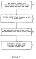
- Fig. 5 illustrates a general procedure of this invention.
- RAID management system 16 maps the physical storage space provided by disk array 12 into a first or RAID-level virtual storage space 40 (Fig. 4).
- the RAID-level virtual storage space presents the physical storage space as mirror and parity RAID areas.
- the mirror RAID areas contain mirror allocation blocks which store data according to mirror redundancy or RAID Level 1.
- the parity RAID areas contain parity allocation blocks which store data according to parity redundancy or RAID Level 5.
- the RAID management system reserves an amount of unused storage space in the RAID-level virtual storage space 40.
- the amount of reserved unused storage space is equivalent to the amount of storage space in one RAID area.
- the unused storage space need not be reserved in a preselected contiguous RAID area. Instead, the method of this invention uses unused storage space that can be distributed non-contiguously over more than one RAID area.
- FIG. 6 shows this space reservation technique.
- An example heterogeneous disk array 68 is depicted as comprising five storage disks 0-4 of varying capacities. Unused storage space (represented by the label "U") is distributed across the storage disk in a non-contiguous manner. The reserved storage space is the logical equivalent to one RAID area. That is, if all the unused storage space U distributed throughout the disks were accumulated, it would fill at least one contiguous RAID area (reserved space U0-U4).
- the amount of unused storage space is equivalent to the size of one largest parity RAID area.
- a largest RAID area is one that spans all of the disks in the disk array, as some non-largest RAID areas may span less than all disks.
- all RAID areas span all storage disks. Thus, each RAID area can be considered as the largest.
- the RAID management system maps the RAID-level virtual storage space into a second or application-level virtual storage space 50 which presents the physical storage space as multiple virtual blocks.
- the application-level virtual storage space does not see the capacity provided by the reserved storage space.
- RAID management system 16 migrates data between mirror and parity RAID areas using the unused storage space, as described above in the two enumerated processes discussed with reference to Fig. 4. This data migration helps ensure that the data storage system does not place too much data in mirror storage such that the one parity RAID area threshold of unused storage space is violated.
- the unused storage space reservation technique of this invention is advantageous because the unused space can be distributed in a non-contiguous manner throughout different RAID areas, and across multiple storage disks. There is no requirement that contiguous reserved storage be guaranteed. As a result, the system can be designed without difficult and complex operations, such as nesting transactions, which guarantee a specific configuration of physical storage space.
- Non-contiguous unused storage space is collected or used in differing ways depending upon the operation in progress. In general, the reserved amount is used to help create usable allocation blocks for storage of user or unused RAID areas that can be converted to mirror or parity RAID areas as needed.
- Two operations of particular interest concern (1) writing a single virtual block to mirrored storage and (2) rewriting whole RAID areas.
- a method for writing a single virtual block includes a sequence of gathering unused storage space via a technique called "garbage collection" and migration of data from mirror to parity storage. The garbage collection/migration method is described in more detail with reference to Figs. 7-9.
- a method for rewriting whole RAID areas concerns emptying a partially filled RAID area in order to convert the emptied RAID area to a mirror or parity RAID area as needed via a technique called "bootstrapping".
- the bootstrapping method is described in more detail with reference to Figs. 10 and 11.
- Fig. 7 shows the method for writing data to single mirror virtual blocks of mirror storage.
- the initial three steps 70, 72, and 74 are essentially identical to steps 60, 62, and 62, which are described above with reference to Fig. 5. These three steps create the two levels of virtual storage space described above in detail with reference to Fig. 4, while reserving an amount of unused storage space in the RAID-level virtual storage space that is equivalent in size to one RAID area. It is noted that the RAID-level virtual storage space mapped in step 70 includes unused RAID areas which have not been designated as mirror or parity RAID areas and are therefore free to be used as either.
- the RAID management system 16 When it is time to write data to a single virtual block, the RAID management system 16 first attempts to locate a usable mirror allocation block in the RAID-level virtual storage space that can be associated with the single virtual block (step 76). If there is a usable mirror allocation block that can be used without violating the one RAID area threshold of unused storage space reserved for migration (i.e., the "yes" branch from decisional step 78), data is simply written to the located mirror allocation block (step 80). On the other hand, if a usable mirror allocation block can not be found (i.e., the "no" branch from decisional step 78), the RAID management system creates at least one usable mirror allocation block (step 82). Thereafter, data is written to the created mirror allocation block(s).
- Fig. 8 illustrates preferred techniques for creating usable mirror allocation blocks per step 82.
- the techniques are preferably conducted in sequential order as shown until at least one usable mirror allocation block is created.
- it is determined whether there is any unused RAID area that can be converted to a mirror RAID area without violating the one RAID area threshold for unused storage space. This determination is made because conversion of an unused RAID area to a mirror RAID area might shrink the available storage space to a point where the one RAID area threshold for unused storage space is violated.
- the threshold is assumed to be equivalent in size to the largest parity RAID area.
- a parity RAID area has a multiple m of N-1 allocation blocks for storage of user data and allocation blocks for redundancy data.
- a mirror RAID area has a multiple of N/2 allocation blocks for storage of user data and N/2 allocation blocks for redundancy data. Conversion from an unused RAID area, which can be converted to either a mirror or parity RAID area, effectively reduces storage space by a multiple of N/2 - (N-1). Thus, the conversion may violate the one RAID area threshold for unused storage.
- the RAID management system converts the unused RAID area to a mirror RAID area (step 100). If successful, this technique creates at least one mirror allocation block. Data can then be written to the usable mirror allocation block within the new mirror RAID area. The process can then be halted.
- the RAID management system next determines whether the storage system has more unused allocation blocks than the reserved threshold amount of unused storage (step 92). If it does, the RAID management system conducts a second space management technique which packs the parity storage with the goal of producing an unused RAID area (step 94).
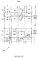
- Fig. 9 shows a section of a disk array 86 containing four storage disks 0-3.
- the RAID areas of the RAID-level virtual storage space are mapped contiguously onto areas A G-1 , A G , A G+1 ,...,A H-1 , A H , A H+1 ,..., etc.
- Areas A G-1 , A G , A G+1 are used for mirror storage and areas A H-1 , A H , A H+1 are associated with parity storage.
- the regions in the mirror RAID areas contain allocation blocks filled with data D0-D5 and allocation blocks provided with mirror redundancy R0-R5.
- the regions in the parity RAID areas contain allocation blocks holding data D100-D107 and allocation blocks provided for parity redundancy P.
- the enclosed boxes having the identifying label "U" represent reserved unused storage space.
- parity packing step 94 of Fig. 8 data is moved from a selected parity RAID area to the unused storage space U in other parity RAID areas.
- Fig. 9 assume that the parity RAID area associated with physical area A H-1 is selected. Data D100 is moved to unused storage space U located in RAID area A H+1 . Similarly, data D101 is moved to unused storage space U in RAID area A H . This data movement effectively fills the "holes" in the parity RAID areas, making RAID area A H+1 more full. At the same time, the data movement collects the unused storage space into the same RAID area.
- the selected parity area A H-1 is now entirely empty. It can therefore be classified as an unused RAID area.
- the pointers in the virtual block table are updated to reflect the data movement. This effectively gathers unused allocation blocks into an unused RAID area (i.e., the emptied parity RAID area associated with physical area A H-1 ).
- the RAID management system determines whether this packing step created an unused RAID area that can be converted to a mirror RAID area without violating the one RAID area threshold for reserved storage space. If it did (i.e., the "yes" branch from step 96), the created unused RAID area is converted to a mirror RAID area which contains at least one usable mirror allocation blocks (step 100) to which data can be written. With respect to Fig. 9, the data can be stored according to mirror redundancy techniques in physical area A H-1 , thereby re-associating that area as a mirror RAID area.
- step 98 the RAID management system performs a third technique of alternately migrating data from mirror allocation blocks to parity allocation blocks, and then gathering the mirror storage to create an unused RAID area (step 98). It is noted that this migration/gathering technique of step 98 can also be reached via the "no" branch from step 92, in the event that the storage system does not have more unused allocation blocks than the reserved threshold amount.
- the RAID management system migrates data from a mirror allocation block to a parity allocation block using any unused parity allocation blocks or by converting unused RAID areas to parity.
- the mirror storage may then be packed with the goal of producing an unused RAID area.
- Fig. 9 The gathering of unused mirror allocation blocks is also shown in Fig. 9.
- data is moved from a selected mirror RAID area, such as that associated with physical area A G+1 , to the unused storage space U in other mirror storage areas.
- Data D4 is moved to unused storage space U located in RAID areas A G-1 and A G .
- data D5 is moved to unused storage space U in RAID area A G-1 .
- the data movement fills the "holes" in the mirror RAID areas while simultaneously collecting the unused storage space into the same RAID area.
- the selected mirror area A G+1 is now entirely empty and can be classified as an unused RAID area.
- the pointers in the virtual block table are updated to reflect the data movement. This effectively gathers unused allocation blocks into an unused RAID area (i.e., the emptied mirror RAID area associated with physical area A G+1 ).
- the migration and packing steps are repeatedly performed until an unused RAID area is created. Since storing user data in mirror storage occupies more physical storage space compared to storing the same user data in parity storage, migration of mirror allocation blocks to parity RAID areas will result in a net increase in the amount of unused storage. Once an unused RAID area is created, it can be converted to a parity RAID area for additional migration (step 99). Steps 98 and 99 are repeatedly performed until there exists an unused RAID area that can be converted to a mirror RAID area without violating the reserved unused storage threshold per step 96. Because of the reserved amount of unused storage, this process is guaranteed to empty mirror RAID areas so that they can be converted to parity RAID areas. That is, the disk array data storage system can shrink mirror storage as much as needed to satisfy the capacity committed for user data.
- the protocol used to create unused mirror allocation blocks is advantageous because it permits the RAID management system to selectively adjust the memory allocation between parity and mirror areas according to the amount of user data and the size of physical storage space. As data usage and storage capacity vary, the RAID management system maximizes the amount of data held in mirror storage. Thus, most-recently or most-frequently used data is maintained in mirror storage to optimize performance and reliability.
- the RAID management system attempts to avoid the situation in which a storage request must wait for the space-making sequence to yield an unused mirror allocation block by creating unused RAID areas during idle time. However, in some situations, conflicts may arise when storage requests are made during the space-making sequence. The RAID management system resolves any conflicts when the space-making procedures are completed.
- Fig. 10 shows the method for rewriting whole RAID areas using the "bootstrapping" technique.
- the initial three steps 120, 122, and 124 again create the two layer mapping structure described above with respect to Fig. 4, while reserving an amount of unused storage space equivalent to one RAID area.
- the RAID management system locates a mirror or parity RAID area that is partially filled with user data.
- the RAID management system searches for the least filled mirror or parity RAID area.
- the RAID management system then empties the partially filled RAID area by moving the remaining data to unused storage space within the disk array (step 128).
- the data can be moved to any unused storage space in either mirror or parity storage. This process yields a whole RAID area that is empty.
- the emptied RAID area can then be converted to a mirror or parity RAID area as needed (step 130). For instance, data from another RAID area (mirror or parity) can be moved or rewritten to this empty RAID area to facilitate various operations where large scale data movement is desirable from a performance and efficiency perspective. It is desirable, for example, to shuffle whole RAID areas during a rebuild operation (where data redundancy is restored following a disk failure) or a balancing operation (where RAID areas are expanded one-by-one to incorporate new storage space created by adding one or more additional storage disks).
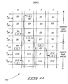
- Fig. 11 diagrammatically illustrates the bootstrapping technique of Fig. 10.
- Fig. 11 shows a section of a disk array 140 containing five storage disks 0-4.
- the regions of each RAID area on the various disks contain allocation blocks for data D0-D15, allocation blocks for mirror redundancy R0-R7 and parity redundancy P, and unused allocation blocks, designated by "U" enclosed in a box. Because of the reserved threshold, the number of unused allocation blocks is greater than or equal to the number of allocation blocks in the largest possible parity RAID area in an N-disk array.
- RAID management system has identified RAID area A PF as the partially-filled RAID area (step 126 in Fig. 10).
- the remaining data in the selected partially filled RAID area A PF is moved to the unused storage space in other RAID areas.
- Data D8 is moved to unused storage space U in mirror RAID areas A PF-4 and A PF-2 and data D9 is moved to unused storage space U in mirror RAID area A PF-1 and parity RAID areas A PF+1 and A PF+2 .
- the data is moved to reserved storage space in the RAID areas throughout the disk array regardless of the level of storage. This process empties the selected RAID area so that it contains no data.
- the selected RAID area A PF can now be converted into a mirror or parity RAID area.
- the bootstrapping process differs from the above garbage collection process in that the data can fill "holes" in any storage level, irrespective of whether the data was originally in a mirror or parity RAID area.
- the process does not completely preserve the maintenance of most-recently or most-frequently used data in mirror storage, but is useful for large rewrites of data in the disk array.
- the bootstrapping process is simpler and faster than the above garbage collection process.
- the methods of this invention have many benefits.
- the data storage system therefore does not need to be designed to support nested transactions which guarantee a specific location or configuration of space reserved for migration between storage types.
- Second, the methods permit maximum flexibility to storage type sizes by easily adopting to homogeneous or heterogenous disk arrays.
- Third, the methods seek to optimize performance and reliability by keeping as much data in mirror storage as possible.
Abstract
Description
Claims (11)
- A method for using a reserved amount of unused storage space in a hierarchic data storage system (10); the data storage system comprising multiple storage disks (12) that define a physical storage space (34); the storage space being presented to a user program having user data in virtual blocks (52, 53) of an application-level virtual storage space (50), the method comprising the following steps:wherein the virtual blocks (52, 53) at the application-level storage space (50) are associated with the first or second allocation blocks (43, 45) at the RAID level storage space (40) via pointers maintained in a virtual block table; andproviding a reserved minimum amount of unused storage space within the RAID-level virtual storage space (40);mapping the physical storage space (34) into a RAID-level virtual storage space (40) having multiple first and second RAID areas, the first RAID areas having first allocation blocks which store data according to a first RAID level having a first redundancy and the second RAID areas having second allocation blocks which store data according to a second RAID level having a second redundancy, wherein the first RAID level is higher than the second RAID level,
depending upon the amount of user data and the size of the physical storage space, increasing or decreasing the number of first (42) and second (44) RAID areas by migrating data from a first allocation block (43) of a first RAID area (42) to a second allocation block (45) of a second RAID area (44) so that data once stored according to the first RAID level is now stored according to the second RAID level or migrating data from a second allocation block (45) of a second RAID area (44) to a first allocation block (43) of a first RAID area (42) so that data once stored according to the second RAID level is now stored according to the first RAID level respectively, such that the unused storage space does not become less than said minimum amount of unused storage space. - A method according to claim 1 further comprising:providing N storage disks in the data storage system (10); andproviding a minimum reserved amount of unused storage space that is equivalent to at least a number of virtual blocks that can be stored in a largest possible RAID area of a multiple of N-1.
- A method according to claim 1,
the RAID-level virtual storage space (40) having mirror, parity, and unused RAID areas; the mirror RAID areas having mirror allocation blocks which store data according to mirror redundancy, the parity RAID areas having parity allocation blocks which store data according to parity redundancy, and the unused RAID areas containing no data;
wherein the minimum reserved amount of unused storage space within the RAID-level virtual storage space (40) can be allowed to distribute across the storage disks;
the method further comprising:attempting to locate a usable mirror allocation block; in the event that a usable mirror allocation block is located, writing data to the mirror allocation block; andin the event that no usable mirror allocation block is located, creating a usable mirror allocation block to receive the data by conducting at least one of the following additional steps:(1) locating an unused RAID area and converting it to a mirror RAID area containing a usable mirror allocation block;(2) gathering empty mirror allocation blocks or empty parity allocation blocks into an unused RAID area that may be used to create a mirror RAID area; and(3) migrating data from mirror allocation blocks to parity allocation blocks and gathering unused mirror allocation blocks into unused RAID areas. - A method according to claim 3 wherein the step of creating a usable mirror allocation block comprises the following steps in sequential order until a usable mirror allocation block is created:(1) locating an unused RAID area and converting it to a mirror RAID area containing a usable mirror allocation block;(2) gathering empty parity allocation blocks into an unused RAID area and converting the unused RAID area to a mirror RAID area containing a usable mirror allocation block; and(3) alternately performing the following steps (a) and (b) until an unused RAID area is created, then performing step (c):(a) migrating data from a mirror allocation block to a parity allocation block to empty the mirror allocation block;(b) gathering the empty mirror allocation block into an unused RAID area; and(c) following said steps (3)(a) and (3)(b), converting the unused RAID area into a parity RAID area; repeating said steps (3)(a)-(3)(c) until an unused RAID area is created that can be converted into a mirror RAID area without violating the minimum reserved amount of unused storage space.
- A method according to claim 1 further comprising:providing a minimum number of unused allocation blocks within the RAID-level virtual storage space (40) that can be distributed across the storage disks;migrating data between the first and second allocation blocks so that the data once stored according to one of the first or second RAID levels is now stored according to the other of the first or second RAID levels;locating a first or second RAID area that is partially filled with data; andemptying the located RAID area by moving the data from the located RAID area to unused allocation blocks.
- A method according to claim 5 further comprising:providing N storage disks in the data storage system (10); andproviding a minimum reserved amount of unused storage space that is equivalent to at least a number of virtual blocks that can be stored in a largest possible RAID area of a multiple of N-1.
- A method according to claim 5 wherein the locating step comprises locating a first or second RAID area that contains the least amount of data stored therein.
- A method according to claim 5 further comprising the additional step of rewriting data from a whole RAID area to the emptied RAID area.
- A method according to claim 5 further comprising the additional step of converting the emptied RAID area to one of a mirror or parity RAID area.
- A method according to claim 5 wherein:the step of providing a minimum number of unused allocation blocks comprises providing unused allocation blocks in both the first and second RAID areas; andthe step of emptying a located RAID area comprises moving data from the located RAID area to unused allocation blocks in both the first RAID areas of the first RAID level and the second RAID areas of the second RAID level.
- The method according to claim 1 further comprising the step of updating the pointers in the virtual block table to reflect the data migration.
Applications Claiming Priority (2)
| Application Number | Priority Date | Filing Date | Title |
|---|---|---|---|
| US08/386,573 US5542065A (en) | 1995-02-10 | 1995-02-10 | Methods for using non-contiguously reserved storage space for data migration in a redundant hierarchic data storage system |
| US386573 | 1995-02-10 |
Publications (3)
| Publication Number | Publication Date |
|---|---|
| EP0726514A2 EP0726514A2 (en) | 1996-08-14 |
| EP0726514A3 EP0726514A3 (en) | 2000-02-23 |
| EP0726514B1 true EP0726514B1 (en) | 2005-10-19 |
Family
ID=23526163
Family Applications (1)
| Application Number | Title | Priority Date | Filing Date |
|---|---|---|---|
| EP95112454A Expired - Lifetime EP0726514B1 (en) | 1995-02-10 | 1995-08-08 | Methods for using non contiguously reserved storage space for data migration in a redundant hierarchic data storage system |
Country Status (4)
| Country | Link |
|---|---|
| US (1) | US5542065A (en) |
| EP (1) | EP0726514B1 (en) |
| JP (1) | JP3778980B2 (en) |
| DE (1) | DE69534527T2 (en) |
Families Citing this family (88)
| Publication number | Priority date | Publication date | Assignee | Title |
|---|---|---|---|---|
| JP3315779B2 (en) * | 1993-11-16 | 2002-08-19 | 富士通株式会社 | File transfer device and file transfer method between disk devices |
| JP3371044B2 (en) * | 1994-12-28 | 2003-01-27 | 株式会社日立製作所 | Area allocation method and disk array access method for disk array |
| US5666512A (en) * | 1995-02-10 | 1997-09-09 | Hewlett-Packard Company | Disk array having hot spare resources and methods for using hot spare resources to store user data |
| US5604902A (en) * | 1995-02-16 | 1997-02-18 | Hewlett-Packard Company | Hole plugging garbage collection for a data storage system |
| US5657468A (en) * | 1995-08-17 | 1997-08-12 | Ambex Technologies, Inc. | Method and apparatus for improving performance in a reduntant array of independent disks |
| US6098128A (en) | 1995-09-18 | 2000-08-01 | Cyberstorage Systems Corporation | Universal storage management system |
| US5809285A (en) * | 1995-12-21 | 1998-09-15 | Compaq Computer Corporation | Computer system having a virtual drive array controller |
| US5809228A (en) * | 1995-12-27 | 1998-09-15 | Intel Corporaiton | Method and apparatus for combining multiple writes to a memory resource utilizing a write buffer |
| US5758050A (en) * | 1996-03-12 | 1998-05-26 | International Business Machines Corporation | Reconfigurable data storage system |
| US5790774A (en) * | 1996-05-21 | 1998-08-04 | Storage Computer Corporation | Data storage system with dedicated allocation of parity storage and parity reads and writes only on operations requiring parity information |
| US5854942A (en) * | 1996-09-06 | 1998-12-29 | International Business Machines Corporation | Method and system for automatic storage subsystem configuration |
| DE69635713T2 (en) | 1996-09-20 | 2006-09-14 | Hitachi, Ltd. | Disk array subsystem |
| US5875457A (en) * | 1996-10-08 | 1999-02-23 | Mylex Corporation | Fault-tolerant preservation of data integrity during dynamic raid set expansion |
| US6154853A (en) * | 1997-03-26 | 2000-11-28 | Emc Corporation | Method and apparatus for dynamic sparing in a RAID storage system |
| US5953352A (en) * | 1997-06-23 | 1999-09-14 | Micron Electronics, Inc. | Method of checking data integrity for a raid 1 system |
| US6061822A (en) * | 1997-06-23 | 2000-05-09 | Micron Electronics, Inc. | System and method for providing a fast and efficient comparison of cyclic redundancy check (CRC/checks sum) values of two mirrored disks |
| US6237063B1 (en) | 1997-10-06 | 2001-05-22 | Emc Corporation | Load balancing method for exchanging data in different physical disk storage devices in a disk array storage device independently of data processing system operation |
| US6105103A (en) * | 1997-12-19 | 2000-08-15 | Lsi Logic Corporation | Method for mapping in dynamically addressed storage subsystems |
| US6098119A (en) * | 1998-01-21 | 2000-08-01 | Mylex Corporation | Apparatus and method that automatically scans for and configures previously non-configured disk drives in accordance with a particular raid level based on the needed raid level |
| US6199146B1 (en) * | 1998-03-12 | 2001-03-06 | International Business Machines Corporation | Storage management system and method for increasing capacity utilization of nonvolatile storage devices using partially filled substitute storage devices for continuing write operations |
| JP3505093B2 (en) | 1998-09-18 | 2004-03-08 | 富士通株式会社 | File management system |
| US6530035B1 (en) * | 1998-10-23 | 2003-03-04 | Oracle Corporation | Method and system for managing storage systems containing redundancy data |
| US6311251B1 (en) * | 1998-11-23 | 2001-10-30 | Storage Technology Corporation | System for optimizing data storage in a RAID system |
| US6363457B1 (en) | 1999-02-08 | 2002-03-26 | International Business Machines Corporation | Method and system for non-disruptive addition and deletion of logical devices |
| US6611897B2 (en) | 1999-03-22 | 2003-08-26 | Hitachi, Ltd. | Method and apparatus for implementing redundancy on data stored in a disk array subsystem based on use frequency or importance of the data |
| US6378038B1 (en) * | 1999-03-31 | 2002-04-23 | International Business Machines Corporation | Method and system for caching data using raid level selection |
| US6854034B1 (en) * | 1999-08-27 | 2005-02-08 | Hitachi, Ltd. | Computer system and a method of assigning a storage device to a computer |
| US6493796B1 (en) * | 1999-09-01 | 2002-12-10 | Emc Corporation | Method and apparatus for maintaining consistency of data stored in a group of mirroring devices |
| US6611827B1 (en) | 1999-10-01 | 2003-08-26 | International Business Machines Corporation | Redundant disk array and method for redundant disk array access using contiguous page grouping |
| US6857058B1 (en) | 1999-10-04 | 2005-02-15 | Intel Corporation | Apparatus to map pages of disparate sizes and associated methods |
| US6970992B2 (en) * | 1999-10-04 | 2005-11-29 | Intel Corporation | Apparatus to map virtual pages to disparate-sized, non-contiguous real pages and methods relating thereto |
| US6546499B1 (en) | 1999-10-14 | 2003-04-08 | International Business Machines Corporation | Redundant array of inexpensive platters (RAIP) |
| US6745207B2 (en) * | 2000-06-02 | 2004-06-01 | Hewlett-Packard Development Company, L.P. | System and method for managing virtual storage |
| US6530004B1 (en) | 2000-06-20 | 2003-03-04 | International Business Machines Corporation | Efficient fault-tolerant preservation of data integrity during dynamic RAID data migration |
| US6820182B1 (en) * | 2000-10-18 | 2004-11-16 | International Business Machines Corporation | Support for exhaustion recovery in a data processing system with memory mirroring |
| US6990667B2 (en) | 2001-01-29 | 2006-01-24 | Adaptec, Inc. | Server-independent object positioning for load balancing drives and servers |
| US7054927B2 (en) | 2001-01-29 | 2006-05-30 | Adaptec, Inc. | File system metadata describing server directory information |
| US6862692B2 (en) | 2001-01-29 | 2005-03-01 | Adaptec, Inc. | Dynamic redistribution of parity groups |
| US20020124137A1 (en) * | 2001-01-29 | 2002-09-05 | Ulrich Thomas R. | Enhancing disk array performance via variable parity based load balancing |
| US20020138559A1 (en) * | 2001-01-29 | 2002-09-26 | Ulrich Thomas R. | Dynamically distributed file system |
| US6990547B2 (en) * | 2001-01-29 | 2006-01-24 | Adaptec, Inc. | Replacing file system processors by hot swapping |
| US6754773B2 (en) | 2001-01-29 | 2004-06-22 | Snap Appliance, Inc. | Data engine with metadata processor |
| US6785836B2 (en) | 2001-04-11 | 2004-08-31 | Broadcom Corporation | In-place data transformation for fault-tolerant disk storage systems |
| GB2375847B (en) * | 2001-05-22 | 2005-03-16 | Hewlett Packard Co | Protection and restoration of RAID configuration information in disaster recovery process |
| US7055056B2 (en) * | 2001-11-21 | 2006-05-30 | Hewlett-Packard Development Company, L.P. | System and method for ensuring the availability of a storage system |
| US7111117B2 (en) * | 2001-12-19 | 2006-09-19 | Broadcom Corporation | Expansion of RAID subsystems using spare space with immediate access to new space |
| US7171396B2 (en) * | 2002-04-04 | 2007-01-30 | Hewlett-Packard Development Company, L.P. | Method and program product for specifying the different data access route for the first data set includes storing an indication of the different access for the first data set providing alternative data access routes to a data storage |
| US6912635B2 (en) * | 2002-05-08 | 2005-06-28 | Hewlett-Packard Development Company, L.P. | Distributing workload evenly across storage media in a storage array |
| US6928509B2 (en) * | 2002-08-01 | 2005-08-09 | International Business Machines Corporation | Method and apparatus for enhancing reliability and scalability of serial storage devices |
| US7089395B2 (en) * | 2002-10-03 | 2006-08-08 | Hewlett-Packard Development Company, L.P. | Computer systems, virtual storage systems and virtual storage system operational methods |
| US7747660B1 (en) * | 2003-03-24 | 2010-06-29 | Symantec Operating Corporation | Method and system of providing access to a virtual storage device |
| US7707186B2 (en) * | 2004-06-18 | 2010-04-27 | Emc Corporation | Method and apparatus for data set migration |
| US7065611B2 (en) * | 2004-06-29 | 2006-06-20 | Hitachi, Ltd. | Method for controlling storage policy according to volume activity |
| US7873782B2 (en) * | 2004-11-05 | 2011-01-18 | Data Robotics, Inc. | Filesystem-aware block storage system, apparatus, and method |
| US9043639B2 (en) * | 2004-11-05 | 2015-05-26 | Drobo, Inc. | Dynamically expandable and contractible fault-tolerant storage system with virtual hot spare |
| US7254686B2 (en) * | 2005-03-31 | 2007-08-07 | International Business Machines Corporation | Switching between mirrored and non-mirrored volumes |
| US20070214314A1 (en) * | 2006-03-07 | 2007-09-13 | Reuter James M | Methods and systems for hierarchical management of distributed data |
| JP2008015769A (en) * | 2006-07-05 | 2008-01-24 | Hitachi Ltd | Storage system and writing distribution method |
| US7743276B2 (en) * | 2006-09-27 | 2010-06-22 | Hewlett-Packard Development Company, L.P. | Sufficient free space for redundancy recovery within a distributed data-storage system |
| JP2010511963A (en) * | 2006-12-08 | 2010-04-15 | サンドフォース インコーポレイテッド | Data redundancy across multiple storage devices |
| JP5080201B2 (en) * | 2007-10-22 | 2012-11-21 | 京セラドキュメントソリューションズ株式会社 | Information processing apparatus and device driver provided therein |
| US8060772B2 (en) * | 2008-01-04 | 2011-11-15 | International Business Machines Corporation | Storage redundant array of independent drives |
| US8713127B2 (en) * | 2008-02-05 | 2014-04-29 | Novell, Inc. | Techniques for distributed storage aggregation |
| US20110119462A1 (en) * | 2009-11-19 | 2011-05-19 | Ocz Technology Group, Inc. | Method for restoring and maintaining solid-state drive performance |
| JP5552924B2 (en) * | 2010-06-30 | 2014-07-16 | 富士通株式会社 | Storage control program, storage system, and storage control method |
| US8667248B1 (en) * | 2010-08-31 | 2014-03-04 | Western Digital Technologies, Inc. | Data storage device using metadata and mapping table to identify valid user data on non-volatile media |
| WO2012045529A1 (en) | 2010-10-07 | 2012-04-12 | International Business Machines Corporation | Raid array transformation |
| CN102446072B (en) | 2010-10-07 | 2014-11-19 | 国际商业机器公司 | System and method for DAID array transformation in a pooled storage system |
| US8719619B2 (en) | 2011-09-20 | 2014-05-06 | International Business Machines Corporation | Performance enhancement technique for raids under rebuild |
| US8869001B1 (en) | 2012-06-27 | 2014-10-21 | Amazon Technologies, Inc. | Layered redundancy encoding schemes for data storage |
| US8850288B1 (en) | 2012-06-27 | 2014-09-30 | Amazon Technologies, Inc. | Throughput-sensitive redundancy encoding schemes for data storage |
| US8806296B1 (en) | 2012-06-27 | 2014-08-12 | Amazon Technologies, Inc. | Scheduled or gradual redundancy encoding schemes for data storage |
| US9110797B1 (en) * | 2012-06-27 | 2015-08-18 | Amazon Technologies, Inc. | Correlated failure zones for data storage |
| US20140181455A1 (en) * | 2012-12-20 | 2014-06-26 | Apple Inc. | Category based space allocation for multiple storage devices |
| US20160080490A1 (en) | 2014-09-15 | 2016-03-17 | Microsoft Corporation | Online data movement without compromising data integrity |
| CN104375784B (en) * | 2014-11-17 | 2018-04-27 | 浙江宇视科技有限公司 | A kind of method and apparatus for reducing virtual disk management complexity |
| US9785575B2 (en) | 2014-12-30 | 2017-10-10 | International Business Machines Corporation | Optimizing thin provisioning in a data storage system through selective use of multiple grain sizes |
| US10366004B2 (en) * | 2016-07-26 | 2019-07-30 | Pure Storage, Inc. | Storage system with elective garbage collection to reduce flash contention |
| WO2018022136A1 (en) | 2016-07-26 | 2018-02-01 | Pure Storage, Inc. | Geometry based, space aware shelf/writegroup evacuation |
| CN106484330A (en) * | 2016-09-27 | 2017-03-08 | 郑州云海信息技术有限公司 | A kind of hybrid magnetic disc individual-layer data optimization method and device |
| US9864534B1 (en) * | 2016-10-27 | 2018-01-09 | International Business Machines Corporation | Validation of storage volumes that are in a peer to peer remote copy relationship |
| US10168948B2 (en) * | 2017-02-20 | 2019-01-01 | International Business Machines Corporation | Replicating data in a data storage system |
| US10852966B1 (en) * | 2017-10-18 | 2020-12-01 | EMC IP Holding Company, LLC | System and method for creating mapped RAID group during expansion of extent pool |
| JP6734305B2 (en) * | 2018-01-10 | 2020-08-05 | Necプラットフォームズ株式会社 | Disk array controller, storage device, storage device recovery method, and disk array controller recovery program |
| CN111104049B (en) * | 2018-10-26 | 2023-08-22 | 伊姆西Ip控股有限责任公司 | Method, apparatus and computer readable storage medium for managing redundant array of disks |
| US11171671B2 (en) * | 2019-02-25 | 2021-11-09 | Samsung Electronics Co., Ltd. | Reducing vulnerability window in key value storage server without sacrificing usable capacity |
| US11556270B2 (en) * | 2021-01-07 | 2023-01-17 | EMC IP Holding Company LLC | Leveraging garbage collection for raid transformation |
| CN117041256B (en) * | 2023-10-08 | 2024-02-02 | 深圳市连用科技有限公司 | Network data transmission and storage method and system |
Family Cites Families (15)
| Publication number | Priority date | Publication date | Assignee | Title |
|---|---|---|---|---|
| US5095420A (en) * | 1988-11-21 | 1992-03-10 | International Business Machines | Method and system for performing virtual address range mapping in a virtual storage data processing system |
| JPH0792775B2 (en) * | 1989-12-11 | 1995-10-09 | 株式会社日立製作所 | Space management method for external storage devices |
| US5195100A (en) * | 1990-03-02 | 1993-03-16 | Micro Technology, Inc. | Non-volatile memory storage of write operation identifier in data sotrage device |
| US5166939A (en) * | 1990-03-02 | 1992-11-24 | Micro Technology, Inc. | Data storage apparatus and method |
| US5155835A (en) * | 1990-11-19 | 1992-10-13 | Storage Technology Corporation | Multilevel, hierarchical, dynamically mapped data storage subsystem |
| US5278838A (en) * | 1991-06-18 | 1994-01-11 | Ibm Corp. | Recovery from errors in a redundant array of disk drives |
| JP2550239B2 (en) * | 1991-09-12 | 1996-11-06 | 株式会社日立製作所 | External storage system |
| US5237658A (en) * | 1991-10-01 | 1993-08-17 | Tandem Computers Incorporated | Linear and orthogonal expansion of array storage in multiprocessor computing systems |
| US5297258A (en) * | 1991-11-21 | 1994-03-22 | Ast Research, Inc. | Data logging for hard disk data storage systems |
| US5287462A (en) * | 1991-12-20 | 1994-02-15 | Ncr Corporation | Bufferless SCSI to SCSI data transfer scheme for disk array applications |
| US5289418A (en) * | 1992-02-14 | 1994-02-22 | Extended Systems, Inc. | Memory apparatus with built-in parity generation |
| JP3183719B2 (en) * | 1992-08-26 | 2001-07-09 | 三菱電機株式会社 | Array type recording device |
| US5416915A (en) * | 1992-12-11 | 1995-05-16 | International Business Machines Corporation | Method and system for minimizing seek affinity and enhancing write sensitivity in a DASD array |
| US5392244A (en) * | 1993-08-19 | 1995-02-21 | Hewlett-Packard Company | Memory systems with data storage redundancy management |
| US5488701A (en) * | 1994-11-17 | 1996-01-30 | International Business Machines Corporation | In log sparing for log structured arrays |
-
1995
- 1995-02-10 US US08/386,573 patent/US5542065A/en not_active Expired - Lifetime
- 1995-08-08 EP EP95112454A patent/EP0726514B1/en not_active Expired - Lifetime
- 1995-08-08 DE DE69534527T patent/DE69534527T2/en not_active Expired - Fee Related
- 1995-12-22 JP JP33459195A patent/JP3778980B2/en not_active Expired - Fee Related
Also Published As
| Publication number | Publication date |
|---|---|
| EP0726514A2 (en) | 1996-08-14 |
| US5542065A (en) | 1996-07-30 |
| EP0726514A3 (en) | 2000-02-23 |
| DE69534527D1 (en) | 2006-03-02 |
| DE69534527T2 (en) | 2006-07-13 |
| JP3778980B2 (en) | 2006-05-24 |
| JPH08272548A (en) | 1996-10-18 |
Similar Documents
| Publication | Publication Date | Title |
|---|---|---|
| EP0726514B1 (en) | Methods for using non contiguously reserved storage space for data migration in a redundant hierarchic data storage system | |
| EP0706113B1 (en) | Method for adding storage disks to a hierarchic disk array while maintaining data availability | |
| EP0726520B1 (en) | Disk array having redundant storage and methods for incrementally generating redundancy as data is written to the disk array | |
| EP0726521B1 (en) | Disk array having hot spare resources and methods for using hot spare resources to store user data | |
| EP0686907B1 (en) | Memory system with hierarchic disk array and memory map store for persistent storage of virtual mapping information | |
| EP0715249B1 (en) | Methods of and system for reserving storage space for data migration in a redundant hierarchic data storage system by dynamically computing maximum storage space for mirror redundancy | |
| EP0639811B1 (en) | Memory systems with data storage redundancy management | |
| EP0709765B1 (en) | Method and system for selecting data for migration in a hierarchic data storage system using frequency distribution tables | |
| US5696934A (en) | Method of utilizing storage disks of differing capacity in a single storage volume in a hierarchial disk array | |
| EP0725324B1 (en) | Methods for avoiding overcommitment of virtual capacity in a redundant hierarchic data storage system | |
| EP0706127B1 (en) | Method and system for detecting data loss in a hierarchic data storage system | |
| US6941420B2 (en) | Log-structure array | |
| JP3687111B2 (en) | Storage device system and storage device control method | |
| US6934803B2 (en) | Methods and structure for multi-drive mirroring in a resource constrained raid controller |
Legal Events
| Date | Code | Title | Description |
|---|---|---|---|
| PUAI | Public reference made under article 153(3) epc to a published international application that has entered the european phase |
Free format text: ORIGINAL CODE: 0009012 |
|
| AK | Designated contracting states |
Kind code of ref document: A2 Designated state(s): DE FR GB IT |
|
| PUAL | Search report despatched |
Free format text: ORIGINAL CODE: 0009013 |
|
| AK | Designated contracting states |
Kind code of ref document: A3 Designated state(s): DE FR GB IT |
|
| 17P | Request for examination filed |
Effective date: 20000210 |
|
| RAP1 | Party data changed (applicant data changed or rights of an application transferred) |
Owner name: HEWLETT-PACKARD COMPANY, A DELAWARE CORPORATION |
|
| 17Q | First examination report despatched |
Effective date: 20030509 |
|
| GRAP | Despatch of communication of intention to grant a patent |
Free format text: ORIGINAL CODE: EPIDOSNIGR1 |
|
| GRAS | Grant fee paid |
Free format text: ORIGINAL CODE: EPIDOSNIGR3 |
|
| GRAA | (expected) grant |
Free format text: ORIGINAL CODE: 0009210 |
|
| AK | Designated contracting states |
Kind code of ref document: B1 Designated state(s): DE FR GB IT |
|
| REG | Reference to a national code |
Ref country code: GB Ref legal event code: FG4D |
|
| REF | Corresponds to: |
Ref document number: 69534527 Country of ref document: DE Date of ref document: 20060302 Kind code of ref document: P |
|
| ET | Fr: translation filed | ||
| PLBE | No opposition filed within time limit |
Free format text: ORIGINAL CODE: 0009261 |
|
| STAA | Information on the status of an ep patent application or granted ep patent |
Free format text: STATUS: NO OPPOSITION FILED WITHIN TIME LIMIT |
|
| 26N | No opposition filed |
Effective date: 20060720 |
|
| PGFP | Annual fee paid to national office [announced via postgrant information from national office to epo] |
Ref country code: DE Payment date: 20061002 Year of fee payment: 12 |
|
| PGFP | Annual fee paid to national office [announced via postgrant information from national office to epo] |
Ref country code: IT Payment date: 20070829 Year of fee payment: 13 |
|
| PGFP | Annual fee paid to national office [announced via postgrant information from national office to epo] |
Ref country code: FR Payment date: 20070817 Year of fee payment: 13 |
|
| PG25 | Lapsed in a contracting state [announced via postgrant information from national office to epo] |
Ref country code: DE Free format text: LAPSE BECAUSE OF NON-PAYMENT OF DUE FEES Effective date: 20080301 |
|
| REG | Reference to a national code |
Ref country code: FR Ref legal event code: ST Effective date: 20090430 |
|
| PG25 | Lapsed in a contracting state [announced via postgrant information from national office to epo] |
Ref country code: IT Free format text: LAPSE BECAUSE OF NON-PAYMENT OF DUE FEES Effective date: 20080808 Ref country code: FR Free format text: LAPSE BECAUSE OF NON-PAYMENT OF DUE FEES Effective date: 20080901 |
|
| PGFP | Annual fee paid to national office [announced via postgrant information from national office to epo] |
Ref country code: GB Payment date: 20090825 Year of fee payment: 15 |
|
| GBPC | Gb: european patent ceased through non-payment of renewal fee |
Effective date: 20100808 |
|
| PG25 | Lapsed in a contracting state [announced via postgrant information from national office to epo] |
Ref country code: GB Free format text: LAPSE BECAUSE OF NON-PAYMENT OF DUE FEES Effective date: 20100808 |