EP0727769A2 - Method of and apparatus for noise reduction - Google Patents
Method of and apparatus for noise reduction Download PDFInfo
- Publication number
- EP0727769A2 EP0727769A2 EP96301059A EP96301059A EP0727769A2 EP 0727769 A2 EP0727769 A2 EP 0727769A2 EP 96301059 A EP96301059 A EP 96301059A EP 96301059 A EP96301059 A EP 96301059A EP 0727769 A2 EP0727769 A2 EP 0727769A2
- Authority
- EP
- European Patent Office
- Prior art keywords
- noise
- value
- level
- signal
- speech signal
- Prior art date
- Legal status (The legal status is an assumption and is not a legal conclusion. Google has not performed a legal analysis and makes no representation as to the accuracy of the status listed.)
- Granted
Links
Images


Classifications
-
- G—PHYSICS
- G10—MUSICAL INSTRUMENTS; ACOUSTICS
- G10L—SPEECH ANALYSIS OR SYNTHESIS; SPEECH RECOGNITION; SPEECH OR VOICE PROCESSING; SPEECH OR AUDIO CODING OR DECODING
- G10L21/00—Processing of the speech or voice signal to produce another audible or non-audible signal, e.g. visual or tactile, in order to modify its quality or its intelligibility
- G10L21/02—Speech enhancement, e.g. noise reduction or echo cancellation
- G10L21/0208—Noise filtering
- G10L21/0216—Noise filtering characterised by the method used for estimating noise
- G10L2021/02161—Number of inputs available containing the signal or the noise to be suppressed
- G10L2021/02163—Only one microphone
-
- G—PHYSICS
- G10—MUSICAL INSTRUMENTS; ACOUSTICS
- G10L—SPEECH ANALYSIS OR SYNTHESIS; SPEECH RECOGNITION; SPEECH OR VOICE PROCESSING; SPEECH OR AUDIO CODING OR DECODING
- G10L21/00—Processing of the speech or voice signal to produce another audible or non-audible signal, e.g. visual or tactile, in order to modify its quality or its intelligibility
- G10L21/02—Speech enhancement, e.g. noise reduction or echo cancellation
- G10L21/0208—Noise filtering
- G10L21/0216—Noise filtering characterised by the method used for estimating noise
- G10L21/0232—Processing in the frequency domain
-
- G—PHYSICS
- G10—MUSICAL INSTRUMENTS; ACOUSTICS
- G10L—SPEECH ANALYSIS OR SYNTHESIS; SPEECH RECOGNITION; SPEECH OR VOICE PROCESSING; SPEECH OR AUDIO CODING OR DECODING
- G10L25/00—Speech or voice analysis techniques not restricted to a single one of groups G10L15/00 - G10L21/00
- G10L25/27—Speech or voice analysis techniques not restricted to a single one of groups G10L15/00 - G10L21/00 characterised by the analysis technique
Definitions
- This invention relates to a method of, and apparatus for removing, suppressing or reducing the noise contained in a speech signal.
- Such speech enhancement or noise reducing technique employs a technique of discriminating a noise domain by comparing the input power or level to a pre-set threshold value.
- a time constant of the threshold value is increased with this technique for prohibiting the threshold value from tracking the speech, a changing noise level, especially an increasing noise level, cannot be followed appropriately, thus leading occasionally to mistaken discrimination.
- noise suppression is achieved by adaptively controlling a maximum likelihood filter configured for calculating a speech component based upon the SNR derived from the input speech signal and the speech presence probability.
- This method employs a signal corresponding to the input speech spectrum less the estimated noise spectrum in calculating the speech presence probability.
- a method of reducing the noise in an input speech signal for noise suppression comprising:
- the present invention provides an apparatus for reducing the noise in an input speech signal for noise suppression comprising:
- the first value is a value calculated on the basis of the ratio of the input signal spectrum obtained by transform from the input speech signal to the estimated noise spectrum contained in the input signal spectrum, and sets an initial value of filter characteristics determining the noise reduction amount in the filtering for noise reduction.
- the second value is a value calculated on the basis of the maximum value of the ratio of the signal level of the input signa spectrum to the estimated noise level, that is the maximum SNR, and the estimated noise level, and is a value for variably controlling the filter characteristics.
- the noise may be removed in an amount corresponding to the maximum SNR from the input speech signal by the filtering conforming to the filter characteristics variably controlled by the first and second values.
- the processing volume may be advantageously reduced.
- the filter characteristics may be adjusted so that the maximum noise reduction amount by the filtering will be changed substantially linearly in a dB area responsive to the maximum SN ratio.
- the first and the second value are used for controlling the filter characteristics for filtering for removing the noise from the input speech signal, whereby the noise may be removed from the input speech signal by filtering conforming to the maximum SNR in the input speech signal, in particular, the distortion in the speech signal caused by the filtering at the high SN ratio may be diminished and the volume of the processing operations for achieving the filter characteristics may also be reduced.
- the first value for controlling the filter characteristics may be calculated using a table having the levels of the input signal spectrum and the levels of the estimated noise spectrum entered therein for reducing the processing volume for achieving the filter characteristics.
- the second value obtained responsive to the maximum SN ratio and to the frame-based noise level may be used for controlling the filter characteristics for reducing the processing volume for achieving the filter characteristics.
- the maximum noise reduction amount achieved by the filter characteristics may be changed responsive to the N ratio of the input speech signal.
- Fig.1 illustrates a first embodiment of the noise reducing method for the speech signal of the present invention, as applied to a noise reducing apparatus.
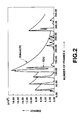
- Fig.2 illustrates a specific example of the energy E[k] and the decay energy E decay [k] in the embodiment of Fig.1.
- Fig.3 illustrates specific examples of an RMS value RMS[k], an estimated noise level value MinRMS[k] and a maximum RMS value MaxRMS[k] in the embodiment of Fig.1.
- Fig.4 illustrates specific examples of the relative energy B rel [k], a maximum SNR MaxSNR[k] in dB, a maximum SNR MaxSNR[k] and a value dBthres rel [k], as one of threshold values for noise discrimination, in the embodiment shown in Fig,1.
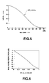
- Fig.5 is a graph showing NR_ level [k] as a function defined with respect to the maximum SNR MaxSNR[k], in the embodiment shown in Fig.1.
- Fig.6 shows the relation between NR[w,k] and the maximum noise reduction amount in dB, in the embodiment shown in Fig.1.
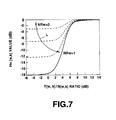
- Fig.7 shows the relation between the ratio of Y[w,k]/N[w, k] and Hn[w,k] responsive to NR[w,k] in dB, in the embodiment shown in Fig.1.
- Fig.8 illustrates a second embodiment of the noise reducing method for the speech signal of the present invention, as applied to a noise reducing apparatus.
- Figs 9 to 10 are graphs showing the distortion of segment portions of the speech signal obtained on noise suppression by the noise reducing apparatus of Figs.1 and 8 with respect to the SN ratio of the segment portions.
- Fig.1 shows an embodiment of a noise reducing apparatus for reducing the noise in a speech signal according to the present invention.
- the noise reducing apparatus includes, as main components, a fast Fourier transform unit 3 for converting the input speech signal into a frequency domain signal or frequency spectra, an Hn value calculation unit 7 for controlling filter characteristics during removing the noise portion from the input speech signal by filtering, and a spectrum correction unit 10 for reducing the noise in the input speech signal by filtering responsive to filtering characteristics produced by the Hn value calculation unit 7.
- a framed signal y_ frame j,k outputted by the framing unit 1 is provided to a windowing unit 2, a root mean square (RMS) calculation unit within a noise estimation unit 5, and a filtering unit 8.
- RMS root mean square
- An output of the windowing unit 2 is provided to the fast fourier transform unit 3, an output of which is provided to both the spectrum correction unit 10 and a band-splitting unit 4.
- An output of the band-splitting unit 3 is provided to the spectrum correction unit 10, a noise spectrum estimation unit 26 within the noise estimation unit 5 and to the Hn value calculation unit 7.
- An output of the spectrum correction unit 10 is provided to a speech signal output terminal 14 via the fast Fourier transform unit 11 and an overlap-and-add unit 12.
- An output of the RMS calculation unit 21 is provided to a relative energy calculation unit 22, a maximum RMS calculation unit 23, an estimated noise level calculation unit 24 and to a noise spectrum estimation unit 26.
- An output of the maximum RMS calculation unit 23 is provided to an estimated noise level calculation unit 24 and to a maximum SNR calculation unit 25.
- An output of the relative energy calculation unit 22 is provided to a noise spectrum estimation unit 26.
- An output of the estimated noise level calculation unit 24 is provided to the filtering unit 8, maximum SNR calculation unit 25, noise spectrum estimation unit 26 and to the NR value calculation unit 6.
- An output of the maximum SNR calculation unit 25 is provided to the NR value calculation unit 6 and to the noise spectrum estimation unit 26, an output of which is provided to the Hn value calculation unit 7.
- An output of the NR value calculation unit 6 is again provided to the NR value calculation unit 6, while being also provided to the Hn value calculation unit 7.
- An output of the Hn value calculation unit 7 is provided via the filtering unit 8 and a band conversion unit 9 to the spectrum correction unit 10.
- the input speech signal y[t] containing a speech component and a noise component.
- the input speech signal y[t] which is a digital signal sample at, for example, a sampling frequency FS, is provided to the framing unit 1 where it is split into plural frames each having a frame length of FL samples.
- the input speech signal y[t], thus split, is then processed on the frame basis.
- the frame interval which is an amount of displacement of the frame along the time axis, is FI samples, so that the (k+1)st frame begins after FI samples as from the k'th frame.
- the sampling frequency FS is 8 kHz
- the frame interval FI of 80 samples corresponds to 10 ms
- the frame length FL of 160 samples corresponds to 20 ms.
- the windowing unit 2 Prior to orthogonal transform calculations by the fast Fourier transform unit 2, the windowing unit 2 multiplies each framed signal y_frame j,k from the framing unit 1 with a windowing function w input . Following the inverse FFI, performed at the terminal stage of the frame-based signal processing operations, as will be explained later, an output signal is multiplied with a windowing function W output .
- the windowing functions w input and w output may be respectively exemplified by the following equations (1) and (2):
- W input [ j ] ( 1 2 - 1 2 cos( 2 ⁇ j FL )) 1 4 , 0 ⁇ j ⁇ FL
- W output [ j ] ( 1 2 - 1 2 cos( 2 ⁇ j FL )) 3 4 , 0 ⁇ j ⁇ FL
- the fast Fourier transform unit 3 then performs 256-point fast Fourier transform operations to produce frequency spectral amplitude values, which then are split by the band splitting portion 4 into, for example, 18 bands.
- the frequency ranges of these bands are shown as an example in Table 1: TABLE 1 band numbers frequency ranges 0 0 to 125 Hz 1 125 to 250 Hz 2 250 to 275 Hz 3 375 to 563 Hz 4 563 to 750 Hz 5 750 to 938 Hz 6 938 to 1125 Hz 7 1125 to 1313 Hz 8 1313 to 1563 Hz 9 1563 to 1813 Hz 10 1813 to 2063 Hz 11 2063 to 2313 Hz 12 2313 to 2563 Hz 13 2563 to 2813 Hz 14 2813 to 3063 hz 15 3063 to 3375 Hz 16 3375 to 3688 Hz 17 3688 to 4000 Hz
- the amplitude values of the frequency bands, resulting from frequency spectrum splitting, become amplitudes Y[w,k] of the input signal spectrum, which are outputted to respective portions, as explained previously.
- the above frequency ranges are based upon the fact that the higher the frequency, the less becomes the perceptual resolution of the human hearing mechanism.
- the maximum FFT amplitudes in the pertinent frequency ranges are employed.
- the noise of the framed signal y_frame j,k is separated from the speech and a frame presumed to be noisy is detected, while the estimated noise level value and the maximum SN ratio are provided to the NR value calculation unit 6.
- the noisy domain estimation or the noisy frame detection is performed by combination of, for example, three detection operations. An illustrative example of the noisy domain estimation is now explained.
- the RMS calculation unit 21 calculates RMS values of signals every frame and outputs the calculated RMS values.
- the RMS value of the k'th frame, or RMS[k] is calculated by the following equation (3):
- the relative energy calculation unit 22 the relative energy of the k'th frame pertinent to the decay energy from the previous frame, or dB rel [k], is calculated, and the resulting value is outputted.
- the relative energy in dB, that is dB rel [k] is found by the following equation (4): while the energy value E[k] and the decay energy value E decay [k] are found from the following equations (5) and (6):
- the equation (5) may be expressed from the equation 1(3) as FL*(RMS[k]) 2 .
- the value of the equation (5), obtained during calculations of the equation (3) by the RMS calculation unit 21, may be directly provided to the relative energy calculation unit 21.
- the decay time is set to 0.65 second.
- Fig.2 shows illustrative examples of the energy value E[k] and the decay energy E decaY [k].
- the maximum RMS calculation unit 23 finds and outputs a maximum RMS value necessary for estimating the maximum value of the ratio of the signal level to the noise level, that is the maximum SN ratio.
- the estimated noise level calculation unit 24 finds and outputs a minimum RMS value suited for evaluating the background noise level.
- This estimated noise level value minRMS[k] is the smallest value of five local minimum values previous to the current time point, that is five values satisfying the equation (8): (RMS[k] ⁇ 0.6*MaxRMS[k] and RMS[k] ⁇ 4000 and RMS[k] ⁇ RMS[k+1] and RMS[k] ⁇ RMS[k-1] and RMS[k] ⁇ RMS[k-2]) or (RMS[k] ⁇ MinRMS)
- the estimated noise level value minRMS[k] is set so as to rise for the background noise freed of speech.
- the rise rate for the high noise level is exponential, while a fixed rise rate is used for the low noise level for realizing a more outstanding rise.
- Fig.3 shows illustrative examples of the RMS values RMS[k], estimated noise level value minRMS[k] and the maximum RMS values MaxRMS[k].
- the maximum SNR calculation unit 25 estimates and calculates the maximum SN ratio MaxSNR[k], using the maximum RMS value and the estimated noise level value, by the following equation (9);
- NR_level in a range from 0 to 1, representing the relative noise level, is calculated.
- NR_level the following function is employed:
- the operation of the noise spectrum estimation unit 26 is explained.
- Fig.4 shows illustrative examples of the relative energy in dB, shown in Fig.ll, that is dB rel [k], the maximum SNR[k] and dBthres rel , as one of the threshold values for noise discrimination.
- Fig.6 shows NR_level[k], as a function of MaxSNR[k] in the equation (10).
- N[w,k-1] is directly used for N[w,k].
- the NR value calculation unit 6 calculates NR[w,k], which is a value used for prohibiting the filter response from being changed abruptly, and outputs the produced value NR[w,k].
- adj2[k] is a value having the effect of suppressing the noise suppression rate with respect to an extremely low noise level or an extremely high noise level, by the above-described filtering operation, and is defined by the following equation (16):
- adj3[k] is a value having the effect of suppressing the maximum noise reduction amount from 18 dB to 15 dB between 2375 Hz and 4000 Hz, and is defined by the following equation (17):
- the Hn value calculation unit 7 generates, from the amplitude Y[w,k] of the input signal spectrum, split into frequency bands, the time averaged estimated value of the noise spectrum N[w,k] and the value NR[w,k], a value Hn[w,k] which determines filter characteristics configured for removing the noise portion from the input speech signal.
- Y w )[S/N r] and p(H0
- Y w )[S/N r] is a parameter specifying the state in which the speech component and the noise component are mixed together in Y[w,k] and P(H0
- Y w )[S/N r] is a parameter specifying that only the noise component is contained in Y[w,k].
- the relation between the Hn[w,k] value produced by the Hn value calculation unit 7, and the x[w,k] value, that is the ratio Y[w,k]/N[w,k], is such that, for a higher value of the ratio Y [w,k]/N[w,k], that is for the speech component being higher than the noisy component, the value Hn[w,k] is increased, that is the suppression is weakened, whereas, for a lower value of the ratio Y[w,k]/N[w,k], that is for the speech component being lower than the noisy component, the value Hn[w,k] is decreased, that is the suppression is intensified.
- the filtering unit 8 performs filtering for smoothing the Hn[w,k] along both the frequency axis and the time axis, so that a smoothed signal Ht_ smooth [w,k] is produced as an output signal.
- the filtering in a direction along the frequency axis has the effect of reducing the effective impulse response length of the signal Hn[w,k]. This prohibits the aliasing from being produced due to cyclic convolution resulting from realization of a filter by multiplication in the frequency domain.
- the filtering in a direction along the time axis has the effect of limiting the rate of change in filter characteristics in suppressing abrupt noise generation.
- H1[w,k] max(median(Hn[w-i,k], Hn[w,k] ,Hn[w+1,k],Hn[w,k])
- H1[w,k] is Hn[w,k] devoid of a sole or lone zero (0) band
- Hn[w,k] is converted into H2[w,k].
- H noise [w, k] 0.7*Min_H+0.3*Max_H
- the signals in the transient state are not smoothed in the direction along the time axis.
- H t_smooth [w, k] (1- ⁇ tr )( ⁇ sp *Hspeech[w,k] + (1- ⁇ sp )*Hnoise[w,k])+ ⁇ tr *H2[w,k]
- the smoothing signal H t_smooth [w,k] for 18 bands from the filtering unit 8 is expanded by interpolation to, for example, a 128-band signal H 128 [w,k], which is outputted.
- This conversion performed by, for example, two stages, while the expansion from 18 to 64 bands and that from 64 bands to 128 bands are performed by zero-order holding and by low pass filter type interpolation, respectively.
- the spectrum correction unit 10 then multiplies the real and imaginary parts of FFT coefficients obtained by fast Fourier transform of the framed signal y_ frame j, k obtained by FFT unit 3 with the above signal H 128 [w,k] by way of performing spectrum correction, that is noise component reduction.
- the resulting signal is outputted. The result is that the spectral amplitudes are corrected without changes in phase.
- the inverse FFT unit 11 then performs inverse FFT on the output signal of the spectrum correction unit 10 in order to output the resultant IFFTed signal.
- the overlap-and-add unit 12 overlaps and adds the frame boundary portions of the frame-based IFFted signals.
- the resulting output speech signals are outputted at a speech signal output terminal 14.
- Fig.8 shows another embodiment of a noise reduction apparatus for carrying out the noise reducing method for a speech signal according to the present invention.
- the parts or components which are used in common with the noise reduction apparatus shown in Fig.1 are represented by the same numerals and the description of the operation is omitted for simplicity.
- the noise reduction apparatus has a fast Fourier transform unit 3 for transforming the input speech signal into a frequency-domain signal, an Hn value calculation unit 7 for controlling filter characteristics of the filtering operation of removing the noise component from the input speech signal, and a spectrum correction unit 10 for reducing the noise in the input speech signal by the filtering operation conforming to filter characteristics obtained by the Hn value calculation unit 7.
- the band splitting portion 4 splits the amplitude of the frequency spectrum outputted from the FFT unit 3 into, for example, 18 bands, and outputs the band-based amplitude Y[w,k] to a calculation unit 31 for calculating the RMS, estimated noise level and the maximum SNR, a noise spectrum estimating unit 26 and to an initial filter response calculation unit 33.
- the calculation unit 31 calculates, from y_frame j,k , outputted from the framing unit 1 and Y[w,k] outputted by the band splitting unit 4, the frame-based RMS value RMS[k], an estimated noise level value MinRMS[k] and a maximum RMS value Max [k], and transmits these values to the noise spectrum estimating unit 26 and an adjl, adj2 and adj3 calculation unit 32.
- the initial filter response calculation unit 33 provides the time-averaged noise value N[w,k] outputted from the noise spectrum estimation unit 26 and Y[w,k] outputted from the band splitting unit 4 to a filter suppression curve table unit 34 for finding out the value of H[w,k] corresponding to Y[w,k] and N [w, k] stored in the filter suppression curve table unit 34 to transmit the value thus found to the Hn value calculation unit 7.
- a filter suppression curve table unit 34 is stored a table for H[w,k] values.
- the output speech signals obtained by the noise reduction apparatus shown in Figs.1 and 8 are provided to a signal processing circuit, such as a variety of encoding circuits for a portable telephone set or to a speech recognition apparatus.
- the noise suppression may be performed on a decoder output signal of the portable telephone set.
- Figs.9 and 10 illustrate the distortion in the speech signals obtained on noise suppression by the noise reduction method of the present invention, shown in black color, and the distortion in the speech signals obtained on noise suppression by the conventional noise reduction method , shown in white color, respectively.
- the SNR values of segments sampled every 20 ms are plotted against the distortion for these segments.
- the SNR values for the segments are plotted against distortion of the entire input speech signal.
- the ordinate stands for distortion which becomes smaller with the height from the origin, while the abscissa stands for the SN ratio of the segments which becomes higher towards right.
- the speech signal obtained on noise suppression by the noise reducing method of the present invention undergoes distortion to a lesser extent especially at a high SNR value exceeding 20.
Abstract
Description
- This invention relates to a method of, and apparatus for removing, suppressing or reducing the noise contained in a speech signal.
- In the fields of portable telephone sets and speech recognition, it is felt to be necessary to suppress the noise such as background noise or environmental noise contained in the collected speech signal for emphasizing its speech components.
- As a technique for emphasizing the speech or reducing the noise, a technique of employing a conditional probability function for attenuation factor adjustment is disclosed in the paper by R.J. McAulay and M.L. Maplass, "Speech Enhancement Using a Soft-Decision noise Suppression Filter, in IEEE Trans. Acoust., Speech Signal Processing, Vol.28, pp.137 to 145, April 1980.
- In the above noise-suppression technique, it is a frequent occurrence that unspontaneous sound tone or distorted speech be produced due to an inappropriate suppression filter or an operation based upon an inappropriate fixed signal-to-noise ratio (SNR). It is not desirable for the user to have to adjust the SNR, as one of the parameters of a noise suppression device, in actual operation for realizing optimum performance. In addition, it is difficult with the conventional speech signal enhancement technique to eliminate the noise sufficiently without generating distortion in a speech signal susceptible to significant variation in the SNR in short time.
- Such speech enhancement or noise reducing technique employs a technique of discriminating a noise domain by comparing the input power or level to a pre-set threshold value. However, if the time constant of the threshold value is increased with this technique for prohibiting the threshold value from tracking the speech, a changing noise level, especially an increasing noise level, cannot be followed appropriately, thus leading occasionally to mistaken discrimination.
- To overcome this drawback, the present inventors have proposed in JP Patent Application Hei-6-99869 (1994) a noise reducing method for reducing the noise in a speech signal.
- With this noise reducing method for the speech signal, noise suppression is achieved by adaptively controlling a maximum likelihood filter configured for calculating a speech component based upon the SNR derived from the input speech signal and the speech presence probability. This method employs a signal corresponding to the input speech spectrum less the estimated noise spectrum in calculating the speech presence probability.
- With this noise reducing method for the speech signal, since the maximum likelihood filter is adjusted to an optimum suppression filter depending upon the SNR of the input speech signal, sufficient noise reduction for the input speech signal may be achieved.
- However, since complex and voluminous processing operations are required for calculating the speech presence probability, it has been desired to simplify the processing operations.
- It is therefore an object of the present invention to provide a noise reducing method for an input speech signal whereby the processing operations for noise suppression for the input speech signal may be simplified.
- According to the present invention, there is provided a method of reducing the noise in an input speech signal for noise suppression comprising:
- converting the input speech signal into a spectrum in the frequency domain;
- determining filter characteristics based upon a first value obtained on the basis of the ratio of a level of the frequency spectrum to an estimated level of the noise spectrum contained in the frequency spectrum and a second value as found from the maximum value of the ratio of the frame-based signal level of the frequency spectrum to the estimated noise level and said estimated noise level; and
- reducing the noise in said input speech signal by filtering responsive to said filter characteristics.
- In another aspect, the present invention provides an apparatus for reducing the noise in an input speech signal for noise suppression comprising:
- means for converting the input speech signal into a spectrum in the frequency domain;
- means for determining filter characteristics based upon a first value obtained on the basis of the ratio of a level of the frequency spectrum to an estimated level of the noise spectrum contained in the frequency spectrum and a second value as found from the maximum value of the ratio of the frame-based signal level of the frequency spectrum to the estimated noise level and said estimated noise level; and
- means for reducing the noise in said input speech signal by filtering responsive to said filter characteristics.
- With the method and apparatus for reducing the noise in the speech signal, according to the present invention, the first value is a value calculated on the basis of the ratio of the input signal spectrum obtained by transform from the input speech signal to the estimated noise spectrum contained in the input signal spectrum, and sets an initial value of filter characteristics determining the noise reduction amount in the filtering for noise reduction. The second value is a value calculated on the basis of the maximum value of the ratio of the signal level of the input signa spectrum to the estimated noise level, that is the maximum SNR, and the estimated noise level, and is a value for variably controlling the filter characteristics. The noise may be removed in an amount corresponding to the maximum SNR from the input speech signal by the filtering conforming to the filter characteristics variably controlled by the first and second values.
- Since a table having pre-set levels of the input signal spectrum and the estimated levels of the noise spectrum entered therein may be used for finding the first value, the processing volume may be advantageously reduced.
- Also, the second value is obtained responsive to the maximum SNR and the frame-based noise level, the filter characteristics may be adjusted so that the maximum noise reduction amount by the filtering will be changed substantially linearly in a dB area responsive to the maximum SN ratio.
- With the above-described noise reducing method of the present invention, the first and the second value are used for controlling the filter characteristics for filtering for removing the noise from the input speech signal, whereby the noise may be removed from the input speech signal by filtering conforming to the maximum SNR in the input speech signal, in particular, the distortion in the speech signal caused by the filtering at the high SN ratio may be diminished and the volume of the processing operations for achieving the filter characteristics may also be reduced.
- In addition, according to the present invention, the first value for controlling the filter characteristics may be calculated using a table having the levels of the input signal spectrum and the levels of the estimated noise spectrum entered therein for reducing the processing volume for achieving the filter characteristics.
- Also, according to the present invention, the second value obtained responsive to the maximum SN ratio and to the frame-based noise level may be used for controlling the filter characteristics for reducing the processing volume for achieving the filter characteristics. The maximum noise reduction amount achieved by the filter characteristics may be changed responsive to the N ratio of the input speech signal.
- The invention will be further described by way of non-limitative example with reference to the accompanying drawings, in which:-
- Fig.1 illustrates a first embodiment of the noise reducing method for the speech signal of the present invention, as applied to a noise reducing apparatus.
- Fig.2 illustrates a specific example of the energy E[k] and the decay energy Edecay[k] in the embodiment of Fig.1.
- Fig.3 illustrates specific examples of an RMS value RMS[k], an estimated noise level value MinRMS[k] and a maximum RMS value MaxRMS[k] in the embodiment of Fig.1.
- Fig.4 illustrates specific examples of the relative energy Brel[k], a maximum SNR MaxSNR[k] in dB, a maximum SNR MaxSNR[k] and a value dBthresrel[k], as one of threshold values for noise discrimination, in the embodiment shown in Fig,1.
- Fig.5 is a graph showing NR_ level [k] as a function defined with respect to the maximum SNR MaxSNR[k], in the embodiment shown in Fig.1.
- Fig.6 shows the relation between NR[w,k] and the maximum noise reduction amount in dB, in the embodiment shown in Fig.1.
- Fig.7 shows the relation between the ratio of Y[w,k]/N[w, k] and Hn[w,k] responsive to NR[w,k] in dB, in the embodiment shown in Fig.1.
- Fig.8 illustrates a second embodiment of the noise reducing method for the speech signal of the present invention, as applied to a noise reducing apparatus.
- Figs 9 to 10 are graphs showing the distortion of segment portions of the speech signal obtained on noise suppression by the noise reducing apparatus of Figs.1 and 8 with respect to the SN ratio of the segment portions.
- Referring to the drawings, a method and apparatus for reducing the noise in the speech signal according to the present invention will be explained in detail.
- Fig.1 shows an embodiment of a noise reducing apparatus for reducing the noise in a speech signal according to the present invention.
- The noise reducing apparatus includes, as main components, a fast
Fourier transform unit 3 for converting the input speech signal into a frequency domain signal or frequency spectra, an Hnvalue calculation unit 7 for controlling filter characteristics during removing the noise portion from the input speech signal by filtering, and aspectrum correction unit 10 for reducing the noise in the input speech signal by filtering responsive to filtering characteristics produced by the Hnvalue calculation unit 7. - An input speech signal y[t], entering a speech
signal input terminal 13 of the noise reducing apparatus, is provided to aframing unit 1. A framed signal y_ framej,k outputted by theframing unit 1, is provided to awindowing unit 2, a root mean square (RMS) calculation unit within anoise estimation unit 5, and afiltering unit 8. - An output of the
windowing unit 2 is provided to the fastfourier transform unit 3, an output of which is provided to both thespectrum correction unit 10 and a band-splitting unit 4. An output of the band-splitting unit 3 is provided to thespectrum correction unit 10, a noisespectrum estimation unit 26 within thenoise estimation unit 5 and to the Hnvalue calculation unit 7. An output of thespectrum correction unit 10 is provided to a speechsignal output terminal 14 via the fast Fourier transform unit 11 and an overlap-and-add unit 12. - An output of the
RMS calculation unit 21 is provided to a relativeenergy calculation unit 22, a maximumRMS calculation unit 23, an estimated noiselevel calculation unit 24 and to a noisespectrum estimation unit 26. An output of the maximumRMS calculation unit 23 is provided to an estimated noiselevel calculation unit 24 and to a maximumSNR calculation unit 25. An output of the relativeenergy calculation unit 22 is provided to a noisespectrum estimation unit 26. An output of the estimated noiselevel calculation unit 24 is provided to thefiltering unit 8, maximumSNR calculation unit 25, noisespectrum estimation unit 26 and to the NRvalue calculation unit 6. An output of the maximumSNR calculation unit 25 is provided to the NRvalue calculation unit 6 and to the noisespectrum estimation unit 26, an output of which is provided to the Hnvalue calculation unit 7. - An output of the NR
value calculation unit 6 is again provided to the NRvalue calculation unit 6, while being also provided to the Hnvalue calculation unit 7. - An output of the Hn
value calculation unit 7 is provided via thefiltering unit 8 and aband conversion unit 9 to thespectrum correction unit 10. - The operation of the above-described first embodiment of the noise reducing apparatus is explained.
- To the speech
signal input terminal 13 is supplied an input speech signal y[t] containing a speech component and a noise component. The input speech signal y[t], which is a digital signal sample at, for example, a sampling frequency FS, is provided to theframing unit 1 where it is split into plural frames each having a frame length of FL samples. The input speech signal y[t], thus split, is then processed on the frame basis. The frame interval, which is an amount of displacement of the frame along the time axis, is FI samples, so that the (k+1)st frame begins after FI samples as from the k'th frame. By way of illustrative examples of the sampling frequency and the number of samples, if the sampling frequency FS is 8 kHz, the frame interval FI of 80 samples corresponds to 10 ms, while the frame length FL of 160 samples corresponds to 20 ms. - Prior to orthogonal transform calculations by the fast
Fourier transform unit 2, thewindowing unit 2 multiplies each framed signal y_framej,k from the framingunit 1 with a windowing function winput. Following the inverse FFI, performed at the terminal stage of the frame-based signal processing operations, as will be explained later, an output signal is multiplied with a windowing function Woutput. The windowing functions winput and woutput may be respectively exemplified by the following equations (1) and (2):

- The fast
Fourier transform unit 3 then performs 256-point fast Fourier transform operations to produce frequency spectral amplitude values, which then are split by theband splitting portion 4 into, for example, 18 bands. The frequency ranges of these bands are shown as an example in Table 1:TABLE 1 band numbers frequency ranges 0 0 to 125 Hz 1 125 to 250 Hz 2 250 to 275 Hz 3 375 to 563 Hz 4 563 to 750 Hz 5 750 to 938 Hz 6 938 to 1125 Hz 7 1125 to 1313 Hz 8 1313 to 1563 Hz 9 1563 to 1813 Hz 10 1813 to 2063 Hz 11 2063 to 2313 Hz 12 2313 to 2563 Hz 13 2563 to 2813 Hz 14 2813 to 3063 hz 15 3063 to 3375 Hz 16 3375 to 3688 Hz 17 3688 to 4000 Hz - The amplitude values of the frequency bands, resulting from frequency spectrum splitting, become amplitudes Y[w,k] of the input signal spectrum, which are outputted to respective portions, as explained previously.
- The above frequency ranges are based upon the fact that the higher the frequency, the less becomes the perceptual resolution of the human hearing mechanism. As the amplitudes of the respective bands, the maximum FFT amplitudes in the pertinent frequency ranges are employed.
- In the
noise estimation unit 5, the noise of the framed signal y_framej,k is separated from the speech and a frame presumed to be noisy is detected, while the estimated noise level value and the maximum SN ratio are provided to the NRvalue calculation unit 6. The noisy domain estimation or the noisy frame detection is performed by combination of, for example, three detection operations. An illustrative example of the noisy domain estimation is now explained. - The
RMS calculation unit 21 calculates RMS values of signals every frame and outputs the calculated RMS values. The RMS value of the k'th frame, or RMS[k], is calculated by the following equation (3):
energy calculation unit 22, the relative energy of the k'th frame pertinent to the decay energy from the previous frame, or dBrel[k], is calculated, and the resulting value is outputted. The relative energy in dB, that is dBrel[k], is found by the following equation (4):


- The equation (5) may be expressed from the equation 1(3) as FL*(RMS[k])2. Of course, the value of the equation (5), obtained during calculations of the equation (3) by the
RMS calculation unit 21, may be directly provided to the relativeenergy calculation unit 21. In the equation (6), the decay time is set to 0.65 second. - Fig.2 shows illustrative examples of the energy value E[k] and the decay energy EdecaY[k].
- The maximum
RMS calculation unit 23 finds and outputs a maximum RMS value necessary for estimating the maximum value of the ratio of the signal level to the noise level, that is the maximum SN ratio. This maximum RMS value MaxRMS[k] may be found by the equation (7):
- The estimated noise
level calculation unit 24 finds and outputs a minimum RMS value suited for evaluating the background noise level. This estimated noise level value minRMS[k] is the smallest value of five local minimum values previous to the current time point, that is five values satisfying the equation (8):
- The estimated noise level value minRMS[k] is set so as to rise for the background noise freed of speech. The rise rate for the high noise level is exponential, while a fixed rise rate is used for the low noise level for realizing a more outstanding rise.
- Fig.3 shows illustrative examples of the RMS values RMS[k], estimated noise level value minRMS[k] and the maximum RMS values MaxRMS[k].
- The maximum
SNR calculation unit 25 estimates and calculates the maximum SN ratio MaxSNR[k], using the maximum RMS value and the estimated noise level value, by the following equation (9);
- From the maximum SNR value MaxSNR, a normalization parameter NR_ level in a range from 0 to 1, representing the relative noise level, is calculated. For NR_level, the following function is employed:

- The operation of the noise
spectrum estimation unit 26 is explained. The respective values found in the relativeenergy calculation unit 22, estimated noiselevel calculation unit 24 and the maximumSNR calculation unit 25 are used for discriminating the speech from the background noise. If the following conditions:

- Fig.4 shows illustrative examples of the relative energy in dB, shown in Fig.ll, that is dBrel[k], the maximum SNR[k] and dBthresrel, as one of the threshold values for noise discrimination.
- Fig.6 shows NR_level[k], as a function of MaxSNR[k] in the equation (10).
- If the k'th frame is classified as the background noise or as the noise, the time averaged estimated value of the noise spectrum N[w,k] is updated by the amplitude Y[w,k] of the input signal spectrum of the signal of the current frame by the following equation (12):


- If the k'th frame is classified as the speech, the value of N[w,k-1] is directly used for N[w,k].
- The NR
value calculation unit 6 calculates NR[w,k], which is a value used for prohibiting the filter response from being changed abruptly, and outputs the produced value NR[w,k]. This NR[w,k] is a value ranging from 0 to 1 and is defined by the equation (13):
adj[w,k] = min(adj1[k],adj2[k])-adj3[w,k] - In the equation (13), adj[w,k] is a parameter used for taking into account the effect as explained below and is defined by the equation (14): δNR = 0.004 and

- In the equation (14), adjl[k] is a value having the effect of suppressing the noise suppressing effect by the filtering at the high SNR by the filtering described below, and is defined by the following equation (15):

- In the equation (14), adj2[k] is a value having the effect of suppressing the noise suppression rate with respect to an extremely low noise level or an extremely high noise level, by the above-described filtering operation, and is defined by the following equation (16):

- In the above equation (14), adj3[k] is a value having the effect of suppressing the maximum noise reduction amount from 18 dB to 15 dB between 2375 Hz and 4000 Hz, and is defined by the following equation (17):

- Meanwhile, it is seen that the relation between the above values of NR[w,k] and the maximum noise reduction amount in dB is substantially linear in the dB region, as shown in Fig.6.
- The Hn
value calculation unit 7 generates, from the amplitude Y[w,k] of the input signal spectrum, split into frequency bands, the time averaged estimated value of the noise spectrum N[w,k] and the value NR[w,k], a value Hn[w,k] which determines filter characteristics configured for removing the noise portion from the input speech signal. The value Hn[w,k] is calculated based upon the following equation (18):
- The value H[w][S/N=r] in the above equation (18) is equivalent to optimum characteristics of a noise suppression filter when the SNR is fixed at a value r, and is found by the following equation (19):

- Meanwhile, this value may be found previously and listed in a table in accordance with the value of Y[w,k]/N[w.k]. Meanwhile, x[w,k] in the equation (19) is equivalent to Y[w,k]/N [w,k], while Gmin is a parameter indicating the minimum gain of H[w][S/N=r]. On the other hand, P(Hi|Yw)[S/N=r] and p(H0|Yw[S/N =r] are parameters specifying the states of the amplitude Y[w, k] while P(H1|Yw)[S/N=r] is a parameter specifying the state in which the speech component and the noise component are mixed together in Y[w,k] and P(H0|Yw)[S/N=r] is a parameter specifying that only the noise component is contained in Y[w,k]. These values are calculated in accordance with the equation (20):

- It is seen from the equation (20) that P(H1|Yw)[S/N=r] and P(H0|Yw)[S/N=r] are functions of x[w,k], while Io(2*r*x [w,k]) is a Bessel function and is found responsive to the values of r and [w,k]. Both P(H1) and P(H0) are fixed at 0.5. The processing volume may be reduced to approximately one-fifth of that with the conventional method by simplifying the parameters as described above.
- The relation between the Hn[w,k] value produced by the Hn
value calculation unit 7, and the x[w,k] value, that is the ratio Y[w,k]/N[w,k], is such that, for a higher value of the ratio Y [w,k]/N[w,k], that is for the speech component being higher than the noisy component, the value Hn[w,k] is increased, that is the suppression is weakened, whereas, for a lower value of the ratio Y[w,k]/N[w,k], that is for the speech component being lower than the noisy component, the value Hn[w,k] is decreased, that is the suppression is intensified. In the above equation, a solid line curve stands for the case of r = 2.7, Gmin = -18 dB and NR[w,k] = 1. It is also seen that the curve specifying the above relation is changed within a range L depending upon the NR[w,k] value and that respective curves for the value of NR[w,k] are changed with the same tendency as for NR[w,k] = 1. - The
filtering unit 8 performs filtering for smoothing the Hn[w,k] along both the frequency axis and the time axis, so that a smoothed signal Ht_smooth[w,k] is produced as an output signal. The filtering in a direction along the frequency axis has the effect of reducing the effective impulse response length of the signal Hn[w,k]. This prohibits the aliasing from being produced due to cyclic convolution resulting from realization of a filter by multiplication in the frequency domain. The filtering in a direction along the time axis has the effect of limiting the rate of change in filter characteristics in suppressing abrupt noise generation. - The filtering in the direction along the frequency axis is first explained. Median filtering is performed on Hn[w,k] of each band. This method is shown by the following equations (21) and (22):


- If, in the equations (21) and (22), (w-1) or w+1) is not present, H1[w,k] = Hn[w,k] and H2[w,k] = H1[w,k], respectively.
- In the
step 1, H1[w,k] is Hn[w,k] devoid of a sole or lone zero (0) band, whereas, in the 2, H2[w,k] H1[w,k] devoid of a sole, lone or protruding band. In this manner, Hn[w,k] is converted into H2[w,k]. - Next, filtering in a direction along the time axis is explained. For filtering in a direction along the time axis, the fact that the input signal contains three components, namely the speech, background noise and the transient state representing the transient state of the rising portion of the speech, is taken into account. The speech signal Hspeech[w,k] is smoothed along the time axis, as shown by the equation (23):

- The background noise is smoothed in a direction along the axis as shown in the equation (24):

- In the above equation (24), Min_H and Max_H may be found by Min_H = min(H2[w,k], H2[w,k-1]) and Max_H = max(H2[w,k],H2[w,k-1]), respectively.
- The signals in the transient state are not smoothed in the direction along the time axis.
- Using the above-described smoothed signals, a smoothed output signal Ht_smooth is produced by the equation (25):

- In the above equation (25), αsp and αtr may be respectively found from the equation (26):


- Then, at the
band conversion unit 9, the smoothing signal Ht_smooth[w,k] for 18 bands from thefiltering unit 8 is expanded by interpolation to, for example, a 128-band signal H128[w,k], which is outputted. This conversion s performed by, for example, two stages, while the expansion from 18 to 64 bands and that from 64 bands to 128 bands are performed by zero-order holding and by low pass filter type interpolation, respectively. - The
spectrum correction unit 10 then multiplies the real and imaginary parts of FFT coefficients obtained by fast Fourier transform of the framed signal y_ frame j, k obtained byFFT unit 3 with the above signal H128[w,k] by way of performing spectrum correction, that is noise component reduction. The resulting signal is outputted. The result is that the spectral amplitudes are corrected without changes in phase. - The inverse FFT unit 11 then performs inverse FFT on the output signal of the
spectrum correction unit 10 in order to output the resultant IFFTed signal. - The overlap-and-add
unit 12 overlaps and adds the frame boundary portions of the frame-based IFFted signals. The resulting output speech signals are outputted at a speechsignal output terminal 14. - Fig.8 shows another embodiment of a noise reduction apparatus for carrying out the noise reducing method for a speech signal according to the present invention. The parts or components which are used in common with the noise reduction apparatus shown in Fig.1 are represented by the same numerals and the description of the operation is omitted for simplicity.
- The noise reduction apparatus has a fast
Fourier transform unit 3 for transforming the input speech signal into a frequency-domain signal, an Hnvalue calculation unit 7 for controlling filter characteristics of the filtering operation of removing the noise component from the input speech signal, and aspectrum correction unit 10 for reducing the noise in the input speech signal by the filtering operation conforming to filter characteristics obtained by the Hnvalue calculation unit 7. - In the noise suppression filter
characteristic generating unit 35, having theHn calculation unit 7, theband splitting portion 4 splits the amplitude of the frequency spectrum outputted from theFFT unit 3 into, for example, 18 bands, and outputs the band-based amplitude Y[w,k] to acalculation unit 31 for calculating the RMS, estimated noise level and the maximum SNR, a noisespectrum estimating unit 26 and to an initial filterresponse calculation unit 33. - The
calculation unit 31 calculates, from y_framej,k, outputted from the framingunit 1 and Y[w,k] outputted by theband splitting unit 4, the frame-based RMS value RMS[k], an estimated noise level value MinRMS[k] and a maximum RMS value Max [k], and transmits these values to the noisespectrum estimating unit 26 and an adjl, adj2 andadj3 calculation unit 32. - The initial filter
response calculation unit 33 provides the time-averaged noise value N[w,k] outputted from the noisespectrum estimation unit 26 and Y[w,k] outputted from theband splitting unit 4 to a filter suppressioncurve table unit 34 for finding out the value of H[w,k] corresponding to Y[w,k] and N [w, k] stored in the filter suppressioncurve table unit 34 to transmit the value thus found to the Hnvalue calculation unit 7. In the filter suppressioncurve table unit 34 is stored a table for H[w,k] values. - The output speech signals obtained by the noise reduction apparatus shown in Figs.1 and 8 are provided to a signal processing circuit, such as a variety of encoding circuits for a portable telephone set or to a speech recognition apparatus. Alternatively, the noise suppression may be performed on a decoder output signal of the portable telephone set.
- Figs.9 and 10 illustrate the distortion in the speech signals obtained on noise suppression by the noise reduction method of the present invention, shown in black color, and the distortion in the speech signals obtained on noise suppression by the conventional noise reduction method , shown in white color, respectively. In the graph of Fig.9, the SNR values of segments sampled every 20 ms are plotted against the distortion for these segments. In the graph of Fig.10, the SNR values for the segments are plotted against distortion of the entire input speech signal. In Figs.9 and 10, the ordinate stands for distortion which becomes smaller with the height from the origin, while the abscissa stands for the SN ratio of the segments which becomes higher towards right.
- It is seen from these figures that, as compared to the speech signals obtained by noise suppression by the conventional noise reducing method, the speech signal obtained on noise suppression by the noise reducing method of the present invention undergoes distortion to a lesser extent especially at a high SNR value exceeding 20.
Claims (7)
- A method of reducing the noise in an input speech signal for noise suppression comprising:converting the input speech signal into a spectrum in the frequency domain;determining filter characteristics based upon a first value obtained on the basis of the ratio of a level of the frequency spectrum to an estimated level of the noise spectrum contained in the frequency spectrum and a second value as found from the maximum value of the ratio of the frame-based signal level of the frequency spectrum to the estimated noise level and said estimated noise level; andreducing the noise in said input speech signal by filtering responsive to said filter characteristics.
- The method of noise reduction as claimed in claim 1 wherein said first value is found using a value obtained from a table containing the pre-set levels of the input signal and the estimated levels of the noise spectrum.
- The method of noise reduction as claimed in claim 1 or 2, wherein said second value is a value obtained responsive to the maximum value of the ratio of the signal level to the estimated noise level and the frame-based noise level, and is a value of adjusting the maximum noise reduction amount by filtering conforming to the filter characteristics so that the maximum noise reduction amount will be changed substantially linearly in a dB domain.
- The method for noise reduction as claimed in claim 1, 2 or 3, wherein said estimated noise level is a value obtained on the basis of a root mean square value of the amplitude of the frame-based input signal and the maximum value of the mean root square values, the maximum value of the ratio of the signal level to the estimated noise level is a value calculated on the basis of the maximum value of the root mean squares and the estimated noise level and wherein the maximum value of the root mean squares is a maximum value among the root mean square values of the amplitudes of the frame-based input signal, a value obtained on the basis of the maximum value of the mean root mean squares of the directly previous frame and a pre-set value.
- A method according to any one of claims 1 to 4, wherein the input speech signal is processed as a series of frames, each frame being constituted by a predetermined number of successive samples of a speed signal.
- An apparatus for reducing the noise in an input speech signal for noise suppression comprising:means for converting the input speech signal into a spectrum in the frequency domain;means for determining filter characteristics based upon a first value obtained on the basis of the ratio of a level of the frequency spectrum to an estimated level of the noise spectrum contained in the frequency spectrum and a second value as found from the maximum value of the ratio of the frame-based signal level of the frequency spectrum to the estimated noise level and said estimated noise level; andmeans for reducing the noise in said input speech signal by filtering responsive to said filter characteristics.
- Apparatus according to claim 6 and which is adapted to process the input speech signal as a series of frames, each frame being constituted by a predetermined number of successive samples of a speech signal.
Applications Claiming Priority (3)
| Application Number | Priority Date | Filing Date | Title |
|---|---|---|---|
| JP2933695 | 1995-02-17 | ||
| JP29336/95 | 1995-02-17 | ||
| JP02933695A JP3484801B2 (en) | 1995-02-17 | 1995-02-17 | Method and apparatus for reducing noise of audio signal |
Publications (3)
| Publication Number | Publication Date |
|---|---|
| EP0727769A2 true EP0727769A2 (en) | 1996-08-21 |
| EP0727769A3 EP0727769A3 (en) | 1998-04-29 |
| EP0727769B1 EP0727769B1 (en) | 2001-11-21 |
Family
ID=12273403
Family Applications (1)
| Application Number | Title | Priority Date | Filing Date |
|---|---|---|---|
| EP96301059A Expired - Lifetime EP0727769B1 (en) | 1995-02-17 | 1996-02-16 | Method of and apparatus for noise reduction |
Country Status (17)
| Country | Link |
|---|---|
| US (1) | US6032114A (en) |
| EP (1) | EP0727769B1 (en) |
| JP (1) | JP3484801B2 (en) |
| KR (1) | KR100414841B1 (en) |
| CN (1) | CN1140869A (en) |
| AT (1) | ATE209389T1 (en) |
| AU (1) | AU696187B2 (en) |
| BR (1) | BR9600761A (en) |
| CA (1) | CA2169424C (en) |
| DE (1) | DE69617069T2 (en) |
| ES (1) | ES2163585T3 (en) |
| MY (1) | MY121575A (en) |
| PL (1) | PL184098B1 (en) |
| RU (1) | RU2127454C1 (en) |
| SG (1) | SG52253A1 (en) |
| TR (1) | TR199600132A2 (en) |
| TW (1) | TW297970B (en) |
Cited By (9)
| Publication number | Priority date | Publication date | Assignee | Title |
|---|---|---|---|---|
| EP0683482A2 (en) * | 1994-05-13 | 1995-11-22 | Sony Corporation | Method for reducing noise in speech signal and method for detecting noise domain |
| EP0751491A2 (en) * | 1995-06-30 | 1997-01-02 | Sony Corporation | Method of reducing noise in speech signal |
| WO1997045995A1 (en) * | 1996-05-31 | 1997-12-04 | Philips Electronics N.V. | Arrangement for suppressing an interfering component of an input signal |
| WO2002101729A1 (en) * | 2001-06-06 | 2002-12-19 | Mitsubishi Denki Kabushiki Kaisha | Noise suppressor |
| WO2003025905A1 (en) * | 2001-09-20 | 2003-03-27 | Honeywell, Inc. | Active noise filtering for voice communication systems |
| AU2003209821B2 (en) * | 2002-03-13 | 2006-11-16 | Hear Ip Pty Ltd | A method and system for controlling potentially harmful signals in a signal arranged to convey speech |
| GB2450886A (en) * | 2007-07-10 | 2009-01-14 | Motorola Inc | Voice activity detector that eliminates from enhancement noise sub-frames based on data from neighbouring speech frames |
| US7565283B2 (en) | 2002-03-13 | 2009-07-21 | Hearworks Pty Ltd. | Method and system for controlling potentially harmful signals in a signal arranged to convey speech |
| WO2012109385A1 (en) * | 2011-02-10 | 2012-08-16 | Dolby Laboratories Licensing Corporation | Post-processing including median filtering of noise suppression gains |
Families Citing this family (30)
| Publication number | Priority date | Publication date | Assignee | Title |
|---|---|---|---|---|
| EP0992978A4 (en) * | 1998-03-30 | 2002-01-16 | Mitsubishi Electric Corp | Noise reduction device and a noise reduction method |
| JP3454206B2 (en) | 1999-11-10 | 2003-10-06 | 三菱電機株式会社 | Noise suppression device and noise suppression method |
| WO2002056303A2 (en) * | 2000-11-22 | 2002-07-18 | Defense Group Inc. | Noise filtering utilizing non-gaussian signal statistics |
| US6985859B2 (en) * | 2001-03-28 | 2006-01-10 | Matsushita Electric Industrial Co., Ltd. | Robust word-spotting system using an intelligibility criterion for reliable keyword detection under adverse and unknown noisy environments |
| JP3427381B2 (en) * | 2001-06-20 | 2003-07-14 | 富士通株式会社 | Noise cancellation method and apparatus |
| WO2003001173A1 (en) * | 2001-06-22 | 2003-01-03 | Rti Tech Pte Ltd | A noise-stripping device |
| US6985709B2 (en) * | 2001-06-22 | 2006-01-10 | Intel Corporation | Noise dependent filter |
| RU2206960C1 (en) * | 2002-06-24 | 2003-06-20 | Общество с ограниченной ответственностью "Центр речевых технологий" | Method and device for data signal noise suppression |
| US7016651B1 (en) | 2002-12-17 | 2006-03-21 | Marvell International Ltd. | Apparatus and method for measuring signal quality of a wireless communications link |
| US6920193B2 (en) * | 2002-12-19 | 2005-07-19 | Texas Instruments Incorporated | Wireless receiver using noise levels for combining signals having spatial diversity |
| US6909759B2 (en) * | 2002-12-19 | 2005-06-21 | Texas Instruments Incorporated | Wireless receiver using noise levels for postscaling an equalized signal having temporal diversity |
| US7065166B2 (en) | 2002-12-19 | 2006-06-20 | Texas Instruments Incorporated | Wireless receiver and method for determining a representation of noise level of a signal |
| GB2398913B (en) * | 2003-02-27 | 2005-08-17 | Motorola Inc | Noise estimation in speech recognition |
| CN100417043C (en) * | 2003-08-05 | 2008-09-03 | 华邦电子股份有限公司 | Automatic gain controller and its control method |
| EP1845520A4 (en) * | 2005-02-02 | 2011-08-10 | Fujitsu Ltd | Signal processing method and signal processing device |
| JP4836720B2 (en) * | 2006-09-07 | 2011-12-14 | 株式会社東芝 | Noise suppressor |
| EP2252996A4 (en) | 2008-03-05 | 2012-01-11 | Voiceage Corp | System and method for enhancing a decoded tonal sound signal |
| EP2172930B1 (en) | 2008-03-24 | 2012-02-22 | Victor Company Of Japan, Limited | Audio signal processing device and audio signal processing method |
| KR101475864B1 (en) * | 2008-11-13 | 2014-12-23 | 삼성전자 주식회사 | Apparatus and method for eliminating noise |
| KR101615766B1 (en) * | 2008-12-19 | 2016-05-12 | 엘지전자 주식회사 | Impulsive noise detector, method of detecting impulsive noise and impulsive noise remover system |
| FR2944640A1 (en) * | 2009-04-17 | 2010-10-22 | France Telecom | METHOD AND DEVICE FOR OBJECTIVE EVALUATION OF THE VOICE QUALITY OF A SPEECH SIGNAL TAKING INTO ACCOUNT THE CLASSIFICATION OF THE BACKGROUND NOISE CONTAINED IN THE SIGNAL. |
| US8712076B2 (en) | 2012-02-08 | 2014-04-29 | Dolby Laboratories Licensing Corporation | Post-processing including median filtering of noise suppression gains |
| US9173025B2 (en) | 2012-02-08 | 2015-10-27 | Dolby Laboratories Licensing Corporation | Combined suppression of noise, echo, and out-of-location signals |
| US9231740B2 (en) | 2013-07-12 | 2016-01-05 | Intel Corporation | Transmitter noise in system budget |
| US10504538B2 (en) | 2017-06-01 | 2019-12-10 | Sorenson Ip Holdings, Llc | Noise reduction by application of two thresholds in each frequency band in audio signals |
| CN107786709A (en) * | 2017-11-09 | 2018-03-09 | 广东欧珀移动通信有限公司 | Call noise-reduction method, device, terminal device and computer-readable recording medium |
| CN111199174A (en) * | 2018-11-19 | 2020-05-26 | 北京京东尚科信息技术有限公司 | Information processing method, device, system and computer readable storage medium |
| CN111477237B (en) * | 2019-01-04 | 2022-01-07 | 北京京东尚科信息技术有限公司 | Audio noise reduction method and device and electronic equipment |
| CN111429930B (en) * | 2020-03-16 | 2023-02-28 | 云知声智能科技股份有限公司 | Noise reduction model processing method and system based on adaptive sampling rate |
| CN113035222B (en) * | 2021-02-26 | 2023-10-27 | 北京安声浩朗科技有限公司 | Voice noise reduction method and device, filter determination method and voice interaction equipment |
Citations (4)
| Publication number | Priority date | Publication date | Assignee | Title |
|---|---|---|---|---|
| US5007094A (en) * | 1989-04-07 | 1991-04-09 | Gte Products Corporation | Multipulse excited pole-zero filtering approach for noise reduction |
| EP0451796A1 (en) * | 1990-04-09 | 1991-10-16 | Kabushiki Kaisha Toshiba | Speech detection apparatus with influence of input level and noise reduced |
| US5097510A (en) * | 1989-11-07 | 1992-03-17 | Gs Systems, Inc. | Artificial intelligence pattern-recognition-based noise reduction system for speech processing |
| EP0556992A1 (en) * | 1992-02-14 | 1993-08-25 | Nokia Mobile Phones Ltd. | Noise attenuation system |
Family Cites Families (18)
| Publication number | Priority date | Publication date | Assignee | Title |
|---|---|---|---|---|
| JPS60140399A (en) * | 1983-12-28 | 1985-07-25 | 松下電器産業株式会社 | Noise remover |
| US4630304A (en) * | 1985-07-01 | 1986-12-16 | Motorola, Inc. | Automatic background noise estimator for a noise suppression system |
| US4628529A (en) * | 1985-07-01 | 1986-12-09 | Motorola, Inc. | Noise suppression system |
| US4630305A (en) * | 1985-07-01 | 1986-12-16 | Motorola, Inc. | Automatic gain selector for a noise suppression system |
| IL84948A0 (en) * | 1987-12-25 | 1988-06-30 | D S P Group Israel Ltd | Noise reduction system |
| US5212764A (en) * | 1989-04-19 | 1993-05-18 | Ricoh Company, Ltd. | Noise eliminating apparatus and speech recognition apparatus using the same |
| CA2032765C (en) * | 1989-12-21 | 1995-12-12 | Hidetaka Yoshikawa | Variable rate encoding and communicating apparatus |
| AU633673B2 (en) * | 1990-01-18 | 1993-02-04 | Matsushita Electric Industrial Co., Ltd. | Signal processing device |
| JP2797616B2 (en) * | 1990-03-16 | 1998-09-17 | 松下電器産業株式会社 | Noise suppression device |
| DE69124005T2 (en) * | 1990-05-28 | 1997-07-31 | Matsushita Electric Ind Co Ltd | Speech signal processing device |
| DE4137404C2 (en) * | 1991-11-14 | 1997-07-10 | Philips Broadcast Television S | Method of reducing noise |
| JPH05344010A (en) * | 1992-06-08 | 1993-12-24 | Mitsubishi Electric Corp | Noise reduction device for radio communication equipment |
| JPH06140949A (en) * | 1992-10-27 | 1994-05-20 | Mitsubishi Electric Corp | Noise reduction device |
| US5479560A (en) * | 1992-10-30 | 1995-12-26 | Technology Research Association Of Medical And Welfare Apparatus | Formant detecting device and speech processing apparatus |
| DE69428119T2 (en) * | 1993-07-07 | 2002-03-21 | Picturetel Corp | REDUCING BACKGROUND NOISE FOR LANGUAGE ENHANCEMENT |
| US5617472A (en) * | 1993-12-28 | 1997-04-01 | Nec Corporation | Noise suppression of acoustic signal in telephone set |
| JP3484757B2 (en) * | 1994-05-13 | 2004-01-06 | ソニー株式会社 | Noise reduction method and noise section detection method for voice signal |
| US5544250A (en) * | 1994-07-18 | 1996-08-06 | Motorola | Noise suppression system and method therefor |
-
1995
- 1995-02-17 JP JP02933695A patent/JP3484801B2/en not_active Expired - Lifetime
-
1996
- 1996-02-12 AU AU44444/96A patent/AU696187B2/en not_active Expired
- 1996-02-12 US US08/606,001 patent/US6032114A/en not_active Expired - Lifetime
- 1996-02-13 CA CA002169424A patent/CA2169424C/en not_active Expired - Lifetime
- 1996-02-13 SG SG1996001434A patent/SG52253A1/en unknown
- 1996-02-16 MY MYPI96000633A patent/MY121575A/en unknown
- 1996-02-16 TR TR96/00132A patent/TR199600132A2/en unknown
- 1996-02-16 ES ES96301059T patent/ES2163585T3/en not_active Expired - Lifetime
- 1996-02-16 KR KR1019960003844A patent/KR100414841B1/en not_active IP Right Cessation
- 1996-02-16 DE DE69617069T patent/DE69617069T2/en not_active Expired - Lifetime
- 1996-02-16 PL PL96312845A patent/PL184098B1/en unknown
- 1996-02-16 RU RU96102867/09A patent/RU2127454C1/en not_active IP Right Cessation
- 1996-02-16 BR BR9600761A patent/BR9600761A/en not_active IP Right Cessation
- 1996-02-16 EP EP96301059A patent/EP0727769B1/en not_active Expired - Lifetime
- 1996-02-16 AT AT96301059T patent/ATE209389T1/en not_active IP Right Cessation
- 1996-02-17 CN CN96106052A patent/CN1140869A/en active Pending
- 1996-05-14 TW TW085105684A patent/TW297970B/zh not_active IP Right Cessation
Patent Citations (4)
| Publication number | Priority date | Publication date | Assignee | Title |
|---|---|---|---|---|
| US5007094A (en) * | 1989-04-07 | 1991-04-09 | Gte Products Corporation | Multipulse excited pole-zero filtering approach for noise reduction |
| US5097510A (en) * | 1989-11-07 | 1992-03-17 | Gs Systems, Inc. | Artificial intelligence pattern-recognition-based noise reduction system for speech processing |
| EP0451796A1 (en) * | 1990-04-09 | 1991-10-16 | Kabushiki Kaisha Toshiba | Speech detection apparatus with influence of input level and noise reduced |
| EP0556992A1 (en) * | 1992-02-14 | 1993-08-25 | Nokia Mobile Phones Ltd. | Noise attenuation system |
Cited By (16)
| Publication number | Priority date | Publication date | Assignee | Title |
|---|---|---|---|---|
| EP0683482A3 (en) * | 1994-05-13 | 1997-12-03 | Sony Corporation | Method for reducing noise in speech signal and method for detecting noise domain |
| EP1065657A1 (en) * | 1994-05-13 | 2001-01-03 | Sony Corporation | Method for detecting a noise domain |
| EP0683482A2 (en) * | 1994-05-13 | 1995-11-22 | Sony Corporation | Method for reducing noise in speech signal and method for detecting noise domain |
| EP0751491A2 (en) * | 1995-06-30 | 1997-01-02 | Sony Corporation | Method of reducing noise in speech signal |
| EP0751491A3 (en) * | 1995-06-30 | 1998-04-08 | Sony Corporation | Method of reducing noise in speech signal |
| WO1997045995A1 (en) * | 1996-05-31 | 1997-12-04 | Philips Electronics N.V. | Arrangement for suppressing an interfering component of an input signal |
| US7302065B2 (en) | 2001-06-06 | 2007-11-27 | Mitsubishi Denki Kabushiki Kaisha | Noise suppressor |
| WO2002101729A1 (en) * | 2001-06-06 | 2002-12-19 | Mitsubishi Denki Kabushiki Kaisha | Noise suppressor |
| CN1308914C (en) * | 2001-06-06 | 2007-04-04 | 三菱电机株式会社 | Noise suppressor |
| WO2003025905A1 (en) * | 2001-09-20 | 2003-03-27 | Honeywell, Inc. | Active noise filtering for voice communication systems |
| AU2003209821B2 (en) * | 2002-03-13 | 2006-11-16 | Hear Ip Pty Ltd | A method and system for controlling potentially harmful signals in a signal arranged to convey speech |
| US7565283B2 (en) | 2002-03-13 | 2009-07-21 | Hearworks Pty Ltd. | Method and system for controlling potentially harmful signals in a signal arranged to convey speech |
| GB2450886A (en) * | 2007-07-10 | 2009-01-14 | Motorola Inc | Voice activity detector that eliminates from enhancement noise sub-frames based on data from neighbouring speech frames |
| GB2450886B (en) * | 2007-07-10 | 2009-12-16 | Motorola Inc | Voice activity detector and a method of operation |
| US8909522B2 (en) | 2007-07-10 | 2014-12-09 | Motorola Solutions, Inc. | Voice activity detector based upon a detected change in energy levels between sub-frames and a method of operation |
| WO2012109385A1 (en) * | 2011-02-10 | 2012-08-16 | Dolby Laboratories Licensing Corporation | Post-processing including median filtering of noise suppression gains |
Also Published As
| Publication number | Publication date |
|---|---|
| PL312845A1 (en) | 1996-08-19 |
| KR100414841B1 (en) | 2004-03-10 |
| MY121575A (en) | 2006-02-28 |
| CA2169424C (en) | 2007-07-10 |
| CN1140869A (en) | 1997-01-22 |
| BR9600761A (en) | 1997-12-23 |
| JPH08221093A (en) | 1996-08-30 |
| DE69617069T2 (en) | 2002-07-11 |
| AU696187B2 (en) | 1998-09-03 |
| RU2127454C1 (en) | 1999-03-10 |
| CA2169424A1 (en) | 1996-08-18 |
| EP0727769B1 (en) | 2001-11-21 |
| PL184098B1 (en) | 2002-08-30 |
| DE69617069D1 (en) | 2002-01-03 |
| KR960032294A (en) | 1996-09-17 |
| ES2163585T3 (en) | 2002-02-01 |
| JP3484801B2 (en) | 2004-01-06 |
| AU4444496A (en) | 1996-08-29 |
| ATE209389T1 (en) | 2001-12-15 |
| EP0727769A3 (en) | 1998-04-29 |
| TW297970B (en) | 1997-02-11 |
| TR199600132A2 (en) | 1996-10-21 |
| SG52253A1 (en) | 1998-09-28 |
| US6032114A (en) | 2000-02-29 |
Similar Documents
| Publication | Publication Date | Title |
|---|---|---|
| EP0727769B1 (en) | Method of and apparatus for noise reduction | |
| EP0727768B1 (en) | Method of and apparatus for reducing noise in speech signal | |
| EP1065656B1 (en) | Method for reducing noise in an input speech signal | |
| US5550924A (en) | Reduction of background noise for speech enhancement | |
| US6487257B1 (en) | Signal noise reduction by time-domain spectral subtraction using fixed filters | |
| EP1141948B1 (en) | Method and apparatus for adaptively suppressing noise | |
| EP1326479B2 (en) | Method and apparatus for noise reduction, particularly in hearing aids | |
| US7155385B2 (en) | Automatic gain control for adjusting gain during non-speech portions | |
| US20070232257A1 (en) | Noise suppressor | |
| EP1080463B1 (en) | Signal noise reduction by spectral subtraction using spectrum dependent exponential gain function averaging | |
| US6507623B1 (en) | Signal noise reduction by time-domain spectral subtraction | |
| US20030065509A1 (en) | Method for improving noise reduction in speech transmission in communication systems |
Legal Events
| Date | Code | Title | Description |
|---|---|---|---|
| PUAI | Public reference made under article 153(3) epc to a published international application that has entered the european phase |
Free format text: ORIGINAL CODE: 0009012 |
|
| AK | Designated contracting states |
Kind code of ref document: A2 Designated state(s): AT DE ES FR GB IT NL |
|
| PUAL | Search report despatched |
Free format text: ORIGINAL CODE: 0009013 |
|
| RHK1 | Main classification (correction) |
Ipc: G10L 5/06 |
|
| AK | Designated contracting states |
Kind code of ref document: A3 Designated state(s): AT DE ES FR GB IT NL |
|
| 17P | Request for examination filed |
Effective date: 19981001 |
|
| RIC1 | Information provided on ipc code assigned before grant |
Free format text: 7G 10L 21/02 A, 7G 10L 15/20 B |
|
| GRAG | Despatch of communication of intention to grant |
Free format text: ORIGINAL CODE: EPIDOS AGRA |
|
| 17Q | First examination report despatched |
Effective date: 20010212 |
|
| GRAG | Despatch of communication of intention to grant |
Free format text: ORIGINAL CODE: EPIDOS AGRA |
|
| GRAH | Despatch of communication of intention to grant a patent |
Free format text: ORIGINAL CODE: EPIDOS IGRA |
|
| GRAH | Despatch of communication of intention to grant a patent |
Free format text: ORIGINAL CODE: EPIDOS IGRA |
|
| GRAA | (expected) grant |
Free format text: ORIGINAL CODE: 0009210 |
|
| AK | Designated contracting states |
Kind code of ref document: B1 Designated state(s): AT DE ES FR GB IT NL |
|
| REF | Corresponds to: |
Ref document number: 209389 Country of ref document: AT Date of ref document: 20011215 Kind code of ref document: T |
|
| REG | Reference to a national code |
Ref country code: GB Ref legal event code: IF02 |
|
| REF | Corresponds to: |
Ref document number: 69617069 Country of ref document: DE Date of ref document: 20020103 |
|
| REG | Reference to a national code |
Ref country code: ES Ref legal event code: FG2A Ref document number: 2163585 Country of ref document: ES Kind code of ref document: T3 |
|
| PGFP | Annual fee paid to national office [announced via postgrant information from national office to epo] |
Ref country code: ES Payment date: 20020213 Year of fee payment: 7 Ref country code: AT Payment date: 20020213 Year of fee payment: 7 |
|
| ET | Fr: translation filed | ||
| PLBE | No opposition filed within time limit |
Free format text: ORIGINAL CODE: 0009261 |
|
| STAA | Information on the status of an ep patent application or granted ep patent |
Free format text: STATUS: NO OPPOSITION FILED WITHIN TIME LIMIT |
|
| 26N | No opposition filed | ||
| PG25 | Lapsed in a contracting state [announced via postgrant information from national office to epo] |
Ref country code: AT Free format text: LAPSE BECAUSE OF NON-PAYMENT OF DUE FEES Effective date: 20030216 |
|
| PG25 | Lapsed in a contracting state [announced via postgrant information from national office to epo] |
Ref country code: ES Free format text: LAPSE BECAUSE OF NON-PAYMENT OF DUE FEES Effective date: 20030217 |
|
| REG | Reference to a national code |
Ref country code: ES Ref legal event code: FD2A Effective date: 20030217 |
|
| PG25 | Lapsed in a contracting state [announced via postgrant information from national office to epo] |
Ref country code: IT Free format text: LAPSE BECAUSE OF NON-PAYMENT OF DUE FEES Effective date: 20050216 |
|
| REG | Reference to a national code |
Ref country code: GB Ref legal event code: 746 Effective date: 20120703 |
|
| REG | Reference to a national code |
Ref country code: DE Ref legal event code: R084 Ref document number: 69617069 Country of ref document: DE Effective date: 20120614 |
|
| REG | Reference to a national code |
Ref country code: FR Ref legal event code: PLFP Year of fee payment: 20 |
|
| PGFP | Annual fee paid to national office [announced via postgrant information from national office to epo] |
Ref country code: NL Payment date: 20150218 Year of fee payment: 20 |
|
| PGFP | Annual fee paid to national office [announced via postgrant information from national office to epo] |
Ref country code: DE Payment date: 20150219 Year of fee payment: 20 |
|
| PGFP | Annual fee paid to national office [announced via postgrant information from national office to epo] |
Ref country code: GB Payment date: 20150218 Year of fee payment: 20 Ref country code: FR Payment date: 20150219 Year of fee payment: 20 |
|
| REG | Reference to a national code |
Ref country code: DE Ref legal event code: R071 Ref document number: 69617069 Country of ref document: DE |
|
| REG | Reference to a national code |
Ref country code: NL Ref legal event code: MK Effective date: 20160215 |
|
| REG | Reference to a national code |
Ref country code: GB Ref legal event code: PE20 Expiry date: 20160215 |
|
| PG25 | Lapsed in a contracting state [announced via postgrant information from national office to epo] |
Ref country code: GB Free format text: LAPSE BECAUSE OF EXPIRATION OF PROTECTION Effective date: 20160215 |