EP0730879A1 - Balloon catheter and method for manufacturing such a catheter - Google Patents
Balloon catheter and method for manufacturing such a catheter Download PDFInfo
- Publication number
- EP0730879A1 EP0730879A1 EP96200357A EP96200357A EP0730879A1 EP 0730879 A1 EP0730879 A1 EP 0730879A1 EP 96200357 A EP96200357 A EP 96200357A EP 96200357 A EP96200357 A EP 96200357A EP 0730879 A1 EP0730879 A1 EP 0730879A1
- Authority
- EP
- European Patent Office
- Prior art keywords
- semimanufacture
- mould
- balloon
- balloon member
- ridges
- Prior art date
- Legal status (The legal status is an assumption and is not a legal conclusion. Google has not performed a legal analysis and makes no representation as to the accuracy of the status listed.)
- Granted
Links
Images


Classifications
-
- A—HUMAN NECESSITIES
- A61—MEDICAL OR VETERINARY SCIENCE; HYGIENE
- A61M—DEVICES FOR INTRODUCING MEDIA INTO, OR ONTO, THE BODY; DEVICES FOR TRANSDUCING BODY MEDIA OR FOR TAKING MEDIA FROM THE BODY; DEVICES FOR PRODUCING OR ENDING SLEEP OR STUPOR
- A61M25/00—Catheters; Hollow probes
- A61M25/10—Balloon catheters
- A61M25/1027—Making of balloon catheters
- A61M25/1029—Production methods of the balloon members, e.g. blow-moulding, extruding, deposition or by wrapping a plurality of layers of balloon material around a mandril
-
- A—HUMAN NECESSITIES
- A61—MEDICAL OR VETERINARY SCIENCE; HYGIENE
- A61M—DEVICES FOR INTRODUCING MEDIA INTO, OR ONTO, THE BODY; DEVICES FOR TRANSDUCING BODY MEDIA OR FOR TAKING MEDIA FROM THE BODY; DEVICES FOR PRODUCING OR ENDING SLEEP OR STUPOR
- A61M25/00—Catheters; Hollow probes
- A61M25/10—Balloon catheters
- A61M25/1027—Making of balloon catheters
- A61M25/1038—Wrapping or folding devices for use with balloon catheters
-
- A—HUMAN NECESSITIES
- A61—MEDICAL OR VETERINARY SCIENCE; HYGIENE
- A61M—DEVICES FOR INTRODUCING MEDIA INTO, OR ONTO, THE BODY; DEVICES FOR TRANSDUCING BODY MEDIA OR FOR TAKING MEDIA FROM THE BODY; DEVICES FOR PRODUCING OR ENDING SLEEP OR STUPOR
- A61M25/00—Catheters; Hollow probes
- A61M25/10—Balloon catheters
- A61M25/1002—Balloon catheters characterised by balloon shape
- A61M2025/1004—Balloons with folds, e.g. folded or multifolded
Definitions
- the invention relates to a method for manufacturing a balloon catheter, in particular a balloon catheter with a very large balloon, as is known from US patent application 4 906 244.
- the balloon for such a balloon catheter is made up of a central section with on both sides transition sections to tube-like end sections.
- the balloon is usually manufactured by means of blow-moulding a piece of tube-like semimanufacture.
- the wall of the semimanufacture is relatively thick, so that sufficient material is available for the central section which is to be expanded.
- the wall thickness decreases from that of the tube-like end section to that of the expanded central section.
- the wall of the transition section close to the end section is consequently still relatively thick, which considerably impedes the folding of the balloon into a small diameter. This folding into a small diameter is desirable however, in order to be able to introduce the balloon catheter properly into a patient.
- the wall thickness in the transition section does, in general, not decrease uniformly. There will be sections with a relatively thick wall separated from each other by sections with a relatively thin wall. This further impedes the folding of the balloon into a small diameter.
- the object of the invention is to provide a method for manufacturing such a balloon catheter, resulting in a balloon which can be folded into a small diameter properly.
- the tube-like semimanufacture is preferably manufactured by extrusion and is pre-stretched before it is received in the mould. As a result the material will obtain the optimum properties required for the ensuing blow-moulding process.
- a further advantageous development is characterised in claim 5.
- the ridges of material stretch out fan-shaped in a pattern of spirals extending in a clockwise direction.
- the introduction of the catheter into the patient and the removal thereof later on, can be facilitated by rotating the catheter round its longitudinal axis.
- the ridges of material extending in the folded state in a helical pattern support, on rotation, the movement in a longitudinal direction by a screw action.
- the invention also relates to and provides a balloon catheter manufactured in accordance with the method as characterised in claim 6.
- An advantageous small diameter of the balloon member can be achieved with the measures as set out in claim 7.
- a very gradual transition without bulges is achieved from the end sections to the folded central section.
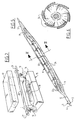
- the catheter 1 shown in figure 1 comprises a tube-like basic body 2 which has been assembled from an outer tube-like element 3, in a central lumen whereof an inner tube-like element 4 has been received.
- the tube-like element 4 also comprises a lumen.
- This connecting element 8 has two connections 5 and 6.
- the connection 5 is connected with the lumen of the inner tube-like element 4 and the connection 6 is connected with the lumen of the outer tube-like element 3, that is to say, the channel with annular cross-section formed by the space not taken up by the inner tube-like element 4 inside the lumen of the outer tube-like element 3.
- a tap 7 known as such, can be arranged to the connection 6.
- the catheter 1 is provided with a balloon member 9.
- This is a balloon with a very large diameter sometimes referred to as a "fatsy”.
- the balloon member 9 has an active central section 10 with on either side transition sections 11 turning into end sections 12.
- the balloon member 9 has been manufactured in at least one step of the blow-moulding process by the method according to the invention. This step will be explained in greater detail with reference to figure 2.
- a mould 15 has been illustrated schematically, comprising two mould sections 16, 17.
- a mould cavity 18 has been provided, the shape of which corresponds with that of an intended expanded form of the balloon member to be manufactured.
- this mould cavity 18 turns into securing elements 19.
- the end sections 21 of a tube-like semimanufacture 20 are secured.
- the semimanufacture 20 is twisted before it is received in the mould 15.
- the end sections 21 are turned over a certain angle in relation to each other.
- a suitable angle is one of 270°.
- a pressure difference between the inside and the outside of the semimanufacture 20 is generated in an obvious manner not explained in greater detail here, for instance by connecting the channel defined inside the semimanufacture 20 to a source of gas under pressure.
- the semimanufacture is heated to a temperature higher than its softening temperature, so that it will be "blown up".
- the inflated section of the semimanufacture 20 arranges itself against the wall of the mould cavity 18 and thus obtains the intended expanded form.
- the balloon member formed can be folded and expanded again afterwards by increasing the pressure inside.
- Figure 3 is a large-scale drawing of the balloon member thus formed. Because the semimanufacture 20 has been received in the mould 15 in the twisted manner described above, ridges of material 22 have been formed in the transition sections 11 extending fan-shaped from the end sections 12. The ridges of material 22 are relatively thick, whereas the material in between is stretched out. The ridges of material 22 have been shown once more in figure 4 for the sake of clarity.
- the ridges of material 22 can, to a certain extent, be compared with the spokes of an umbrella. They can fold against each other, whereby the thinner material inbetween is folded into pleads. Thus, in folded state, a small diameter can be achieved.
- the central section 10 and the transition sections 11 are folded in pleads against the inner tube-like element 4 of the basic body 2.
- the folds 24 fit closely together and substantially coincide with the fan-shaped ridges of material 22.
- the outer tube-like element 3 of the basic body 2 is shorter than the inner tube-like element 4.
- the relatively proximal end section 12 of the balloon member 9 is connected with the end of the outer tube-like element 3, whereas the relatively distal end section 12 of the balloon member 9 is connected with the inner tube-like element 4.
- the inside of the balloon member 9 is therefore connected via the remaining channel with annular cross-section inside the outer tube-like element 3 with the connection 5 of the connecting member 8.
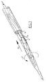
- Introduction occurs in the usual manner via an introduction sheath 26 which has been illustrated schematically in figure 7.
- This introduction sheath 26 can have a relatively small inside diameter, as the balloon member 9 can be folded into a small diameter and because no bulges are formed at the transition sections as a result of unevenly distributed basic material.
- a first initiation can for example be carried out in the form of a limited expansion in order to obtain a second semimanufacture with a suitable material distribution.
- This second semimanufacture can then be expanded in a second blow-moulding step to obtain the intended ultimate form.
- the suitable material distribution is achieved during the first step by the right choice of mould cavity of the mould in which this step is performed.
Abstract
Description
- The invention relates to a method for manufacturing a balloon catheter, in particular a balloon catheter with a very large balloon, as is known from US patent application 4 906 244.
- The balloon for such a balloon catheter is made up of a central section with on both sides transition sections to tube-like end sections. The balloon is usually manufactured by means of blow-moulding a piece of tube-like semimanufacture. The wall of the semimanufacture is relatively thick, so that sufficient material is available for the central section which is to be expanded.
- In the transition sections the wall thickness decreases from that of the tube-like end section to that of the expanded central section. The wall of the transition section close to the end section is consequently still relatively thick, which considerably impedes the folding of the balloon into a small diameter. This folding into a small diameter is desirable however, in order to be able to introduce the balloon catheter properly into a patient.
- What is more, the wall thickness in the transition section does, in general, not decrease uniformly. There will be sections with a relatively thick wall separated from each other by sections with a relatively thin wall. This further impedes the folding of the balloon into a small diameter.
- The object of the invention is to provide a method for manufacturing such a balloon catheter, resulting in a balloon which can be folded into a small diameter properly.
- This aim is achieved with the method as characterised in claim 1. By receiving the semi-manufactured product thus twisted in the mould, ridges of material extending fan-shaped from the end section are formed on expansion in the transition section of the balloon member, of which the walls are thicker than those of the intermediate sections. As a result the transition section can be folded together very easily into a small diameter.
- The tube-like semimanufacture is preferably manufactured by extrusion and is pre-stretched before it is received in the mould. As a result the material will obtain the optimum properties required for the ensuing blow-moulding process.
- An advantageous further development is characterised in
claim 3. By carrying out the blow-moulding process in two stages, an optimum distribution of material can be achieved in the end product. - With the measures as set out in claim 4, a suitable number of evenly distributed fan-shaped ridges of material is obtained. There are approximately ten of them.
- A further advantageous development is characterised in
claim 5. As a result the ridges of material stretch out fan-shaped in a pattern of spirals extending in a clockwise direction. The introduction of the catheter into the patient and the removal thereof later on, can be facilitated by rotating the catheter round its longitudinal axis. The ridges of material extending in the folded state in a helical pattern support, on rotation, the movement in a longitudinal direction by a screw action. - The invention also relates to and provides a balloon catheter manufactured in accordance with the method as characterised in claim 6.
- An advantageous small diameter of the balloon member can be achieved with the measures as set out in claim 7. A very gradual transition without bulges is achieved from the end sections to the folded central section.
- Additional advantageous properties and advantages of the invention will become apparent when reading the following description of an example of an embodiment with reference to the attached drawings.
- Figure 1
- shows a catheter manufactured with the method according to the invention in a partly broken away perspective view,
- Figure 2
- illustrates schematically one step of the method according to the invention,
- Figure 3
- is a large-scale drawing of the balloon member of the catheter of figure 1,
- Figure 4
- shows a frontal view of the balloon member of figure 3 in the direction as indicated by arrow IV,
- Figure 5
- shows the balloon member of figure 3 in the folded state,
- Figure 6
- shows a cross-section along the line VI-VI of figure 5.
- The catheter 1 shown in figure 1 comprises a tube-like
basic body 2 which has been assembled from an outer tube-like element 3, in a central lumen whereof an inner tube-like element 4 has been received. The tube-like element 4 also comprises a lumen. - At the proximal end of the catheter 1 a connecting
element 8 has been arranged. This connectingelement 8 has twoconnections 5 and 6. Theconnection 5 is connected with the lumen of the inner tube-like element 4 and the connection 6 is connected with the lumen of the outer tube-like element 3, that is to say, the channel with annular cross-section formed by the space not taken up by the inner tube-like element 4 inside the lumen of the outer tube-like element 3. - As can be seen in the figure, a tap 7, known as such, can be arranged to the connection 6.
- At the distal end the catheter 1 is provided with a
balloon member 9. This is a balloon with a very large diameter sometimes referred to as a "fatsy". - The
balloon member 9 has an activecentral section 10 with on eitherside transition sections 11 turning intoend sections 12. - The
balloon member 9 has been manufactured in at least one step of the blow-moulding process by the method according to the invention. This step will be explained in greater detail with reference to figure 2. - In figure 2 a
mould 15 has been illustrated schematically, comprising twomould sections mould sections 16 and 17 amould cavity 18 has been provided, the shape of which corresponds with that of an intended expanded form of the balloon member to be manufactured. At opposite ends thismould cavity 18 turns into securingelements 19. In thesecuring elements 19 theend sections 21 of a tube-like semimanufacture 20 are secured. - As is indicated by the arrows, the
semimanufacture 20 is twisted before it is received in themould 15. For this purpose theend sections 21 are turned over a certain angle in relation to each other. A suitable angle is one of 270°. - After receiving the
semimanufacture 20 in themould 15, a pressure difference between the inside and the outside of thesemimanufacture 20 is generated in an obvious manner not explained in greater detail here, for instance by connecting the channel defined inside thesemimanufacture 20 to a source of gas under pressure. At the same time the semimanufacture is heated to a temperature higher than its softening temperature, so that it will be "blown up". The inflated section of thesemimanufacture 20 arranges itself against the wall of themould cavity 18 and thus obtains the intended expanded form. - Next one can allow the semimanufacture to cool down, so that the expanded form is retained. Because of the flexibility of the material of which the semimanufacture has been made, which is a plastic material, the balloon member formed can be folded and expanded again afterwards by increasing the pressure inside.
- Figure 3 is a large-scale drawing of the balloon member thus formed. Because the
semimanufacture 20 has been received in themould 15 in the twisted manner described above, ridges ofmaterial 22 have been formed in thetransition sections 11 extending fan-shaped from theend sections 12. The ridges ofmaterial 22 are relatively thick, whereas the material in between is stretched out. The ridges ofmaterial 22 have been shown once more in figure 4 for the sake of clarity. - The ridges of
material 22 can, to a certain extent, be compared with the spokes of an umbrella. They can fold against each other, whereby the thinner material inbetween is folded into pleads. Thus, in folded state, a small diameter can be achieved. - This folded state is illustrated in the figures 5 up to and including 7.
- As can be seen in the figures 5 and 6, the
central section 10 and thetransition sections 11 are folded in pleads against the inner tube-like element 4 of thebasic body 2. Thefolds 24 fit closely together and substantially coincide with the fan-shaped ridges ofmaterial 22. - As can be seen in figure 5 as well, the outer tube-
like element 3 of thebasic body 2 is shorter than the inner tube-like element 4. The relativelyproximal end section 12 of theballoon member 9 is connected with the end of the outer tube-like element 3, whereas the relativelydistal end section 12 of theballoon member 9 is connected with the inner tube-like element 4. The inside of theballoon member 9 is therefore connected via the remaining channel with annular cross-section inside the outer tube-like element 3 with theconnection 5 of the connectingmember 8. By supplying via this connection a gas or liquid under pressure, theballoon 9 can be unfolded into its expanded form. This occurs following introduction of the catheter into a patient for the purpose of dilation or occlusion of a blood vessel. - Introduction occurs in the usual manner via an
introduction sheath 26 which has been illustrated schematically in figure 7. Thisintroduction sheath 26 can have a relatively small inside diameter, as theballoon member 9 can be folded into a small diameter and because no bulges are formed at the transition sections as a result of unevenly distributed basic material. - As a result of the ridges of material extending in a fan-shaped manner and the closely fitting folds, sections with a helically shaped profile are formed on either side of the balloon member. By rotating the catheter in a suitable manner, as indicated by arrow 27, a certain force 28 can be generated by screw action, which facilitates the introduction of the catheter. Also the removal of the catheter can take place smoothly by applying a correct rotation.
- Although the method according to the invention is explained with reference to figure 2, in which a balloon member is formed in one single blow-moulding step, it is also possible to achieve the same in more steps. A first initiation can for example be carried out in the form of a limited expansion in order to obtain a second semimanufacture with a suitable material distribution. This second semimanufacture can then be expanded in a second blow-moulding step to obtain the intended ultimate form. In that case the suitable material distribution is achieved during the first step by the right choice of mould cavity of the mould in which this step is performed.
Claims (10)
- Method for manufacturing a balloon catheter, comprising the providing of a piece of tube-like basic material, the manufacturing of a balloon member and the connecting of the balloon member with the basic material, wherein the manufacturing of the balloon member comprises the providing of a mould which in its turn has been provided with a mould cavity corresponding to an intended expanded form of the balloon member, turning at opposite ends into securing elements for the purpose of securing opposite end sections of a piece of tube-like semimanufacture inside the mould cavity, the receiving of the semimanufacture in the mould, the heating of the semimanufacture, the generating of a pressure difference between the inside and the outside of the semimanufacture as a result of which it expands into the balloon member arranged against the walls of the mould cavity, wherein the end sections of the semimanufacture on being received in the mould are turned over an angle in relation to each other.
- Method as claimed in claim 1, wherein the tube-like semimanufacture is manufactured by means of extrusion and is pre-stretched before being received in the mould.
- Method as claimed in one of the previous claims, wherein the intended expanded form is an intermediate form, and the heated, expanded balloon member is transferred to a second mould in which it is given its definite shape, and the cooling down of the balloon member.
- Method as claimed in one of the previous claims, wherein the end sections are turned substantially over an angle of 270° in relation to each other.
- Method as claimed in one of the previous claims, wherein the end sections are turned in such a direction, that the semimanufacture is twisted in the direction of a helix extending clockwise.
- Balloon catheter manufactured with the method according to one of the previous claims, wherein the balloon member comprises a central section with on either side transition sections turning into tube-like end sections, of which at least one comprises ridges of material extending fan-shaped from the end section.
- Balloon catheter as claimed in claim 6, wherein the central section and the transition sections are folded in pleads against the basic body and wherein the pleads substantially coincide with the fan-shaped ridges of material.
- Balloon catheter as claimed in claim 6 or 7, wherein the ridges of material are substantially evenly distributed around the circumference of the transition section.
- Balloon catheter according to one of the claims
6-8, wherein the transition section comprises between 5 and 15 ridges of material. - Balloon catheter as claimed in claim 9, wherein the transition section comprises some 10 ridges of material.
Applications Claiming Priority (2)
| Application Number | Priority Date | Filing Date | Title |
|---|---|---|---|
| NL9500468 | 1995-03-08 | ||
| NL9500468A NL9500468A (en) | 1995-03-08 | 1995-03-08 | Balloon catheter and method of making it. |
Publications (2)
| Publication Number | Publication Date |
|---|---|
| EP0730879A1 true EP0730879A1 (en) | 1996-09-11 |
| EP0730879B1 EP0730879B1 (en) | 2002-10-30 |
Family
ID=19865697
Family Applications (1)
| Application Number | Title | Priority Date | Filing Date |
|---|---|---|---|
| EP96200357A Expired - Lifetime EP0730879B1 (en) | 1995-03-08 | 1996-02-14 | Balloon catheter and method for manufacturing such a catheter |
Country Status (6)
| Country | Link |
|---|---|
| US (1) | US5792415A (en) |
| EP (1) | EP0730879B1 (en) |
| JP (1) | JP3830193B2 (en) |
| CA (1) | CA2169673A1 (en) |
| DE (1) | DE69624520T2 (en) |
| NL (1) | NL9500468A (en) |
Cited By (10)
| Publication number | Priority date | Publication date | Assignee | Title |
|---|---|---|---|---|
| WO1998048884A3 (en) * | 1997-05-01 | 1999-01-28 | Chase Medical Inc | Aortic arch occlusion and perfusion balloon catheter having pressure ports |
| WO2000002613A1 (en) * | 1998-07-09 | 2000-01-20 | Scimed Life Systems, Inc. | Method for reducing dilatation balloon cone stiffness |
| EP0935973A3 (en) * | 1998-02-13 | 2000-06-21 | Cordis Corporation | Six-pleated catheter balloon and device for forming same |
| US6607544B1 (en) | 1994-01-26 | 2003-08-19 | Kyphon Inc. | Expandable preformed structures for deployment in interior body regions |
| EP1359966A2 (en) * | 2001-02-16 | 2003-11-12 | Cordis Corporation | Method of balloon catheter stent delivery system with ridges |
| EP1374800A1 (en) * | 2002-06-28 | 2004-01-02 | Cordis Corporation | Balloon-stent interaction to help reduce foreshortening |
| US6719773B1 (en) | 1998-06-01 | 2004-04-13 | Kyphon Inc. | Expandable structures for deployment in interior body regions |
| US7261720B2 (en) | 2002-01-11 | 2007-08-28 | Kyphon Inc. | Inflatable device for use in surgical protocol relating to fixation of bone |
| WO2009146285A1 (en) * | 2008-05-29 | 2009-12-03 | Boston Scientific Scimed, Inc. | Balloon design and weld design to increase ease of re-wrapping and decrease withdrawal force |
| WO2019013577A1 (en) * | 2017-07-14 | 2019-01-17 | 이제권 | Method for manufacturing balloon catheter |
Families Citing this family (61)
| Publication number | Priority date | Publication date | Assignee | Title |
|---|---|---|---|---|
| US6554795B2 (en) | 1997-03-06 | 2003-04-29 | Medtronic Ave, Inc. | Balloon catheter and method of manufacture |
| US20010008661A1 (en) | 1997-05-14 | 2001-07-19 | Eugene J. Jung Jr | Balloon for a dilation catheter and method for manufacturing a balloon |
| CA2232250C (en) * | 1997-05-14 | 2007-06-26 | Navius Corporation | Balloon for a dilation catheter and method for manufacturing a balloon |
| US6221467B1 (en) | 1997-06-03 | 2001-04-24 | Scimed Life Systems, Inc. | Coating gradient for lubricious coatings on balloon catheters |
| US6289568B1 (en) * | 1998-11-16 | 2001-09-18 | Cordis Corporation | Method for making a balloon catheter stent deployment system |
| US6293959B1 (en) | 1998-11-16 | 2001-09-25 | Cordis Corporation | Balloon catheter and stent delivery system having enhanced stent retention and method |
| US6464718B1 (en) | 1998-11-16 | 2002-10-15 | Cordis Corporation | Balloon catheter for stent delivery having microchannels and method |
| US6129706A (en) * | 1998-12-10 | 2000-10-10 | Janacek; Jaroslav | Corrugated catheter balloon |
| US6673053B2 (en) | 1999-05-07 | 2004-01-06 | Scimed Life Systems, Inc. | Hydrophilic lubricity coating for medical devices comprising an antiblock agent |
| US6610035B2 (en) | 1999-05-21 | 2003-08-26 | Scimed Life Systems, Inc. | Hydrophilic lubricity coating for medical devices comprising a hybrid top coat |
| US6176849B1 (en) | 1999-05-21 | 2001-01-23 | Scimed Life Systems, Inc. | Hydrophilic lubricity coating for medical devices comprising a hydrophobic top coat |
| JP3804351B2 (en) | 1999-08-25 | 2006-08-02 | ニプロ株式会社 | Balloon catheter |
| US6360577B2 (en) | 1999-09-22 | 2002-03-26 | Scimed Life Systems, Inc. | Apparatus for contracting, or crimping stents |
| US6458867B1 (en) | 1999-09-28 | 2002-10-01 | Scimed Life Systems, Inc. | Hydrophilic lubricant coatings for medical devices |
| US6629350B2 (en) | 2000-06-08 | 2003-10-07 | Tom Motsenbocker | Stent crimping apparatus and method |
| US7572270B2 (en) | 2001-02-16 | 2009-08-11 | Cordis Corporation | Balloon catheter stent delivery system with ridges |
| JP4782297B2 (en) * | 2001-03-09 | 2011-09-28 | 川澄化学工業株式会社 | Catheter balloon and balloon catheter |
| EP1372924B1 (en) | 2001-03-26 | 2007-08-15 | Machine Solutions, Inc. | Balloon folding technology |
| US6425882B1 (en) * | 2001-05-01 | 2002-07-30 | Interventional Technologies Inc. | Folding spring for a catheter balloon |
| US6712833B1 (en) * | 2001-08-22 | 2004-03-30 | Advanced Cardiovascular Systems, Inc. | Method of making a catheter balloon |
| CA2464053A1 (en) | 2001-11-09 | 2003-05-22 | Novoste Corporation | Baloon catheter with non-deployable stent |
| US20040111108A1 (en) | 2001-11-09 | 2004-06-10 | Farnan Robert C. | Balloon catheter with non-deployable stent |
| US8080026B2 (en) | 2003-01-21 | 2011-12-20 | Angioscore, Inc. | Apparatus and methods for treating hardened vascular lesions |
| US20050021070A1 (en) * | 2003-01-21 | 2005-01-27 | Angioscore, Inc. | Methods and apparatus for manipulating vascular prostheses |
| US7686824B2 (en) | 2003-01-21 | 2010-03-30 | Angioscore, Inc. | Apparatus and methods for treating hardened vascular lesions |
| JPWO2004101057A1 (en) * | 2003-05-19 | 2006-07-13 | 株式会社カネカ | Balloon catheter and balloon catheter manufacturing method |
| US7264458B2 (en) * | 2004-01-07 | 2007-09-04 | Boston Scientific Scimed, Inc. | Process and apparatus for forming medical device balloons |
| US20050177130A1 (en) * | 2004-02-10 | 2005-08-11 | Angioscore, Inc. | Balloon catheter with spiral folds |
| US20050228428A1 (en) * | 2004-04-07 | 2005-10-13 | Afsar Ali | Balloon catheters and methods for manufacturing balloons for balloon catheters |
| US7892478B2 (en) * | 2004-04-19 | 2011-02-22 | Boston Scientific Scimed, Inc. | Catheter balloon mold form and molding process |
| JP2005323714A (en) * | 2004-05-13 | 2005-11-24 | Kaneka Corp | Catheter balloon for medical use |
| US8983582B2 (en) * | 2004-12-20 | 2015-03-17 | Advanced Cardiovascular Systems, Inc. | Methods and apparatuses for positioning within an internal channel |
| US10076641B2 (en) | 2005-05-11 | 2018-09-18 | The Spectranetics Corporation | Methods and systems for delivering substances into luminal walls |
| EP1917062B1 (en) * | 2005-08-19 | 2009-10-21 | Abbott Laboratories Vascular Enterprises Limited | Method of producing a balloon of a balloon catheter and balloon |
| US8876763B2 (en) * | 2005-11-01 | 2014-11-04 | Boston Scientific Scimed, Inc. | Composite balloon |
| US7828766B2 (en) | 2005-12-20 | 2010-11-09 | Advanced Cardiovascular Systems, Inc. | Non-compliant multilayered balloon for a catheter |
| US20080045893A1 (en) * | 2006-02-14 | 2008-02-21 | Cardio Exodus, Llc | Imageable balloon and method of making |
| US7896642B2 (en) * | 2006-08-03 | 2011-03-01 | Boston Scientific Scimed, Inc. | Balloon folding device |
| US20080140174A1 (en) * | 2006-08-17 | 2008-06-12 | Abbott Laboratories | Method of increasing balloon flexibility in a balloon catheter |
| US8177829B2 (en) * | 2006-08-23 | 2012-05-15 | Boston Scientific Scimed, Inc. | Auxiliary balloon catheter |
| US8926620B2 (en) | 2006-08-25 | 2015-01-06 | Kyphon Sarl | Apparatus and methods for use of expandable members in surgical applications |
| US8043362B2 (en) * | 2006-08-25 | 2011-10-25 | Kyphon Sarl | Apparatus and methods for use of expandable members in surgical applications |
| EP2462975B1 (en) * | 2006-10-12 | 2015-09-09 | C. R. Bard, Inc. | Inflatables structure with braided layer |
| US7896840B2 (en) * | 2007-04-05 | 2011-03-01 | Boston Scientific Scimed, Inc. | Catheter having internal mechanisms to encourage balloon re-folding |
| DE102007021116A1 (en) | 2007-05-03 | 2008-11-06 | Pioneer Medical Devices Gmbh | Method for producing balloon of balloon catheter, involves finishing balloon by handle action or by pressing action or by steam action, and balloon is inserted into form case kept at moderate temperature during pressing action |
| JP5428209B2 (en) * | 2008-06-11 | 2014-02-26 | 株式会社カネカ | Medical balloon catheter |
| US8758422B2 (en) * | 2008-06-11 | 2014-06-24 | Boston Scientific Scimed, Inc. | Edge protection via tapered balloon wrap |
| US20100274189A1 (en) * | 2009-04-22 | 2010-10-28 | Pressure Products Medical Supplies Inc. | Balloon catheter and method of manufacture of the same |
| CN102573982B (en) * | 2009-06-08 | 2014-09-03 | 曲利姆医疗股份有限公司 | Side branch balloon |
| US20110230946A1 (en) * | 2010-03-16 | 2011-09-22 | Abbott Laboratories | Easy marker placement balloon mold |
| EP2380604A1 (en) | 2010-04-19 | 2011-10-26 | InnoRa Gmbh | Improved coating formulations for scoring or cutting balloon catheters |
| US8703260B2 (en) | 2010-09-14 | 2014-04-22 | Abbott Cardiovascular Systems Inc. | Catheter balloon and method for forming same |
| US8632559B2 (en) | 2010-09-21 | 2014-01-21 | Angioscore, Inc. | Method and system for treating valve stenosis |
| US9283100B2 (en) * | 2012-05-16 | 2016-03-15 | Abbott Cardiovascular Systems Inc. | Polymer scaffold with multi-pleated balloon |
| US9095321B2 (en) * | 2012-11-21 | 2015-08-04 | Medtronic Ardian Luxembourg S.A.R.L. | Cryotherapeutic devices having integral multi-helical balloons and methods of making the same |
| JP2014161521A (en) * | 2013-02-25 | 2014-09-08 | Sumitomo Bakelite Co Ltd | Balloon catheter |
| US10117668B2 (en) | 2013-10-08 | 2018-11-06 | The Spectranetics Corporation | Balloon catheter with non-deployable stent having improved stability |
| JP6861529B2 (en) * | 2017-02-06 | 2021-04-21 | オリンパス株式会社 | Medical balloon catheter |
| JP2020521611A (en) * | 2017-05-24 | 2020-07-27 | カーディアック アシスト ホールディング, エルエルシー | Aortic spiral balloon pump |
| KR102072058B1 (en) * | 2018-01-02 | 2020-01-31 | 아이메디컴(주) | Balloon manufacturing jig for catheter and balloon manufacturing method using the same |
| CN110420375B (en) * | 2019-06-27 | 2022-09-02 | 先健科技(深圳)有限公司 | Balloon catheter and manufacturing method thereof |
Citations (5)
| Publication number | Priority date | Publication date | Assignee | Title |
|---|---|---|---|---|
| EP0304258A2 (en) * | 1987-08-21 | 1989-02-22 | C.R. Bard, Inc. | Dilatation catheter with collapsible outer diameter |
| US4935190A (en) * | 1987-07-10 | 1990-06-19 | William G. Whitney | Method of making balloon retention catheter |
| EP0376451A2 (en) * | 1988-12-29 | 1990-07-04 | C.R. Bard, Inc. | Dilatation catheter with fluted balloon |
| US5015230A (en) * | 1989-01-30 | 1991-05-14 | Vas-Cath Incorporated | Angioplasty catheter with spiral balloon |
| EP0439202A2 (en) * | 1989-07-24 | 1991-07-31 | Cordis Corporation | Apparatus and method for manufacturing balloons for medical devices |
Family Cites Families (4)
| Publication number | Priority date | Publication date | Assignee | Title |
|---|---|---|---|---|
| US3097058A (en) * | 1960-08-01 | 1963-07-09 | Phillips Petroleum Co | Extrusion of thermoplastic resins |
| JPS5280356A (en) * | 1975-12-27 | 1977-07-06 | Shinko Kagaku Kk | Method of molding bottle by elongating blow |
| US4906244A (en) * | 1988-10-04 | 1990-03-06 | Cordis Corporation | Balloons for medical devices and fabrication thereof |
| US5041125A (en) * | 1989-01-26 | 1991-08-20 | Cordis Corporation | Balloon catheter |
-
1995
- 1995-03-08 NL NL9500468A patent/NL9500468A/en not_active Application Discontinuation
-
1996
- 1996-02-14 DE DE69624520T patent/DE69624520T2/en not_active Expired - Lifetime
- 1996-02-14 EP EP96200357A patent/EP0730879B1/en not_active Expired - Lifetime
- 1996-02-16 CA CA002169673A patent/CA2169673A1/en not_active Abandoned
- 1996-02-26 JP JP03842396A patent/JP3830193B2/en not_active Expired - Lifetime
- 1996-03-07 US US08/612,340 patent/US5792415A/en not_active Expired - Lifetime
Patent Citations (5)
| Publication number | Priority date | Publication date | Assignee | Title |
|---|---|---|---|---|
| US4935190A (en) * | 1987-07-10 | 1990-06-19 | William G. Whitney | Method of making balloon retention catheter |
| EP0304258A2 (en) * | 1987-08-21 | 1989-02-22 | C.R. Bard, Inc. | Dilatation catheter with collapsible outer diameter |
| EP0376451A2 (en) * | 1988-12-29 | 1990-07-04 | C.R. Bard, Inc. | Dilatation catheter with fluted balloon |
| US5015230A (en) * | 1989-01-30 | 1991-05-14 | Vas-Cath Incorporated | Angioplasty catheter with spiral balloon |
| EP0439202A2 (en) * | 1989-07-24 | 1991-07-31 | Cordis Corporation | Apparatus and method for manufacturing balloons for medical devices |
Cited By (19)
| Publication number | Priority date | Publication date | Assignee | Title |
|---|---|---|---|---|
| US6607544B1 (en) | 1994-01-26 | 2003-08-19 | Kyphon Inc. | Expandable preformed structures for deployment in interior body regions |
| US6979341B2 (en) | 1994-01-26 | 2005-12-27 | Kyphon Inc. | Expandable preformed structures for deployment in interior body regions |
| WO1998048884A3 (en) * | 1997-05-01 | 1999-01-28 | Chase Medical Inc | Aortic arch occlusion and perfusion balloon catheter having pressure ports |
| EP0935973A3 (en) * | 1998-02-13 | 2000-06-21 | Cordis Corporation | Six-pleated catheter balloon and device for forming same |
| US6719773B1 (en) | 1998-06-01 | 2004-04-13 | Kyphon Inc. | Expandable structures for deployment in interior body regions |
| US7875035B2 (en) | 1998-06-01 | 2011-01-25 | Kyphon Sarl | Expandable structures for deployment in interior body regions |
| US7722624B2 (en) | 1998-06-01 | 2010-05-25 | Kyphon SÀRL | Expandable structures for deployment in interior body regions |
| US6458313B2 (en) | 1998-07-09 | 2002-10-01 | Schneider (Usa) Inc. | Method for reducing dilation balloon cone stiffness |
| US6287506B1 (en) | 1998-07-09 | 2001-09-11 | Schneider (Usa) Inc. | Method for reducing dilation balloon cone stiffness |
| WO2000002613A1 (en) * | 1998-07-09 | 2000-01-20 | Scimed Life Systems, Inc. | Method for reducing dilatation balloon cone stiffness |
| EP1359966A2 (en) * | 2001-02-16 | 2003-11-12 | Cordis Corporation | Method of balloon catheter stent delivery system with ridges |
| EP1359966A4 (en) * | 2001-02-16 | 2007-04-25 | Cordis Corp | Method of balloon catheter stent delivery system with ridges |
| US7261720B2 (en) | 2002-01-11 | 2007-08-28 | Kyphon Inc. | Inflatable device for use in surgical protocol relating to fixation of bone |
| EP1374800A1 (en) * | 2002-06-28 | 2004-01-02 | Cordis Corporation | Balloon-stent interaction to help reduce foreshortening |
| US6761731B2 (en) | 2002-06-28 | 2004-07-13 | Cordis Corporation | Balloon-stent interaction to help reduce foreshortening |
| WO2009146285A1 (en) * | 2008-05-29 | 2009-12-03 | Boston Scientific Scimed, Inc. | Balloon design and weld design to increase ease of re-wrapping and decrease withdrawal force |
| US7828767B2 (en) | 2008-05-29 | 2010-11-09 | Boston Scientific Scimed, Inc. | Balloon design and weld design to increase ease of re-wrapping and decrease withdrawal force |
| EP2320983B1 (en) | 2008-05-29 | 2015-11-04 | Boston Scientific Scimed, Inc. | Balloon design and weld design to increase ease of re-wrapping and decrease withdrawal force |
| WO2019013577A1 (en) * | 2017-07-14 | 2019-01-17 | 이제권 | Method for manufacturing balloon catheter |
Also Published As
| Publication number | Publication date |
|---|---|
| US5792415A (en) | 1998-08-11 |
| NL9500468A (en) | 1996-10-01 |
| JP3830193B2 (en) | 2006-10-04 |
| EP0730879B1 (en) | 2002-10-30 |
| DE69624520T2 (en) | 2003-06-18 |
| DE69624520D1 (en) | 2002-12-05 |
| CA2169673A1 (en) | 1996-09-09 |
| JPH08299445A (en) | 1996-11-19 |
Similar Documents
| Publication | Publication Date | Title |
|---|---|---|
| EP0730879B1 (en) | Balloon catheter and method for manufacturing such a catheter | |
| US5853389A (en) | Balloon catheter and method for manufacturing | |
| EP0737488A1 (en) | Balloon catheter with lobated balloon and method for manufacturing such a catheter | |
| US6156254A (en) | Method of manufacturing a balloon member for a balloon catheter | |
| JP5005784B2 (en) | catheter | |
| US7252650B1 (en) | Balloon catheter | |
| US5704913A (en) | Dilation catheter and method of treatment therewith | |
| EP2254645B1 (en) | Method of forming a cutting balloon with connector and dilation element | |
| US9572694B2 (en) | Helical graft | |
| US5733299A (en) | Two balloon catheter | |
| US8333795B2 (en) | Bulging balloon for bifurcation catheter assembly and methods | |
| JPH08506752A (en) | Inflatable perfusion catheter | |
| EP1605868B1 (en) | Helical graft | |
| EP0707864B1 (en) | Balloon catheter with several balloons | |
| EP1917062B1 (en) | Method of producing a balloon of a balloon catheter and balloon | |
| JP2009528152A (en) | New balloon catheter mold design | |
| EP1642612B1 (en) | Balloon catheter with lobated balloon and method for manufacturing such a catheter |
Legal Events
| Date | Code | Title | Description |
|---|---|---|---|
| PUAI | Public reference made under article 153(3) epc to a published international application that has entered the european phase |
Free format text: ORIGINAL CODE: 0009012 |
|
| AK | Designated contracting states |
Kind code of ref document: A1 Designated state(s): BE CH DE FR GB IE IT LI NL |
|
| 17P | Request for examination filed |
Effective date: 19970307 |
|
| GRAG | Despatch of communication of intention to grant |
Free format text: ORIGINAL CODE: EPIDOS AGRA |
|
| 17Q | First examination report despatched |
Effective date: 20020125 |
|
| GRAG | Despatch of communication of intention to grant |
Free format text: ORIGINAL CODE: EPIDOS AGRA |
|
| GRAH | Despatch of communication of intention to grant a patent |
Free format text: ORIGINAL CODE: EPIDOS IGRA |
|
| GRAH | Despatch of communication of intention to grant a patent |
Free format text: ORIGINAL CODE: EPIDOS IGRA |
|
| GRAA | (expected) grant |
Free format text: ORIGINAL CODE: 0009210 |
|
| AK | Designated contracting states |
Kind code of ref document: B1 Designated state(s): BE CH DE FR GB IE IT LI NL |
|
| PG25 | Lapsed in a contracting state [announced via postgrant information from national office to epo] |
Ref country code: LI Free format text: LAPSE BECAUSE OF FAILURE TO SUBMIT A TRANSLATION OF THE DESCRIPTION OR TO PAY THE FEE WITHIN THE PRESCRIBED TIME-LIMIT Effective date: 20021030 Ref country code: IT Free format text: LAPSE BECAUSE OF FAILURE TO SUBMIT A TRANSLATION OF THE DESCRIPTION OR TO PAY THE FEE WITHIN THE PRESCRIBED TIME-LIMIT;WARNING: LAPSES OF ITALIAN PATENTS WITH EFFECTIVE DATE BEFORE 2007 MAY HAVE OCCURRED AT ANY TIME BEFORE 2007. THE CORRECT EFFECTIVE DATE MAY BE DIFFERENT FROM THE ONE RECORDED. Effective date: 20021030 Ref country code: FR Free format text: LAPSE BECAUSE OF FAILURE TO SUBMIT A TRANSLATION OF THE DESCRIPTION OR TO PAY THE FEE WITHIN THE PRESCRIBED TIME-LIMIT Effective date: 20021030 Ref country code: CH Free format text: LAPSE BECAUSE OF FAILURE TO SUBMIT A TRANSLATION OF THE DESCRIPTION OR TO PAY THE FEE WITHIN THE PRESCRIBED TIME-LIMIT Effective date: 20021030 |
|
| REG | Reference to a national code |
Ref country code: GB Ref legal event code: FG4D |
|
| REG | Reference to a national code |
Ref country code: CH Ref legal event code: EP |
|
| REG | Reference to a national code |
Ref country code: IE Ref legal event code: FG4D |
|
| REF | Corresponds to: |
Ref document number: 69624520 Country of ref document: DE Date of ref document: 20021205 |
|
| PGFP | Annual fee paid to national office [announced via postgrant information from national office to epo] |
Ref country code: FR Payment date: 20030210 Year of fee payment: 8 |
|
| REG | Reference to a national code |
Ref country code: CH Ref legal event code: PL |
|
| EN | Fr: translation not filed | ||
| PLBE | No opposition filed within time limit |
Free format text: ORIGINAL CODE: 0009261 |
|
| STAA | Information on the status of an ep patent application or granted ep patent |
Free format text: STATUS: NO OPPOSITION FILED WITHIN TIME LIMIT |
|
| 26N | No opposition filed |
Effective date: 20030731 |
|
| PGFP | Annual fee paid to national office [announced via postgrant information from national office to epo] |
Ref country code: NL Payment date: 20150210 Year of fee payment: 20 |
|
| PGFP | Annual fee paid to national office [announced via postgrant information from national office to epo] |
Ref country code: DE Payment date: 20150210 Year of fee payment: 20 Ref country code: IE Payment date: 20150210 Year of fee payment: 20 |
|
| PGFP | Annual fee paid to national office [announced via postgrant information from national office to epo] |
Ref country code: GB Payment date: 20150211 Year of fee payment: 20 |
|
| PGFP | Annual fee paid to national office [announced via postgrant information from national office to epo] |
Ref country code: BE Payment date: 20150211 Year of fee payment: 20 |
|
| REG | Reference to a national code |
Ref country code: DE Ref legal event code: R071 Ref document number: 69624520 Country of ref document: DE |
|
| REG | Reference to a national code |
Ref country code: NL Ref legal event code: MK Effective date: 20160213 |
|
| REG | Reference to a national code |
Ref country code: GB Ref legal event code: PE20 Expiry date: 20160213 |
|
| REG | Reference to a national code |
Ref country code: IE Ref legal event code: MK9A |
|
| PG25 | Lapsed in a contracting state [announced via postgrant information from national office to epo] |
Ref country code: IE Free format text: LAPSE BECAUSE OF EXPIRATION OF PROTECTION Effective date: 20160214 Ref country code: GB Free format text: LAPSE BECAUSE OF EXPIRATION OF PROTECTION Effective date: 20160213 |