EP0732092A2 - Knee joint prosthesis - Google Patents
Knee joint prosthesis Download PDFInfo
- Publication number
- EP0732092A2 EP0732092A2 EP96301666A EP96301666A EP0732092A2 EP 0732092 A2 EP0732092 A2 EP 0732092A2 EP 96301666 A EP96301666 A EP 96301666A EP 96301666 A EP96301666 A EP 96301666A EP 0732092 A2 EP0732092 A2 EP 0732092A2
- Authority
- EP
- European Patent Office
- Prior art keywords
- tibial
- prosthesis
- radius
- femoral component
- sagittal
- Prior art date
- Legal status (The legal status is an assumption and is not a legal conclusion. Google has not performed a legal analysis and makes no representation as to the accuracy of the status listed.)
- Granted
Links
Images


Classifications
-
- A—HUMAN NECESSITIES
- A61—MEDICAL OR VETERINARY SCIENCE; HYGIENE
- A61F—FILTERS IMPLANTABLE INTO BLOOD VESSELS; PROSTHESES; DEVICES PROVIDING PATENCY TO, OR PREVENTING COLLAPSING OF, TUBULAR STRUCTURES OF THE BODY, e.g. STENTS; ORTHOPAEDIC, NURSING OR CONTRACEPTIVE DEVICES; FOMENTATION; TREATMENT OR PROTECTION OF EYES OR EARS; BANDAGES, DRESSINGS OR ABSORBENT PADS; FIRST-AID KITS
- A61F2/00—Filters implantable into blood vessels; Prostheses, i.e. artificial substitutes or replacements for parts of the body; Appliances for connecting them with the body; Devices providing patency to, or preventing collapsing of, tubular structures of the body, e.g. stents
- A61F2/02—Prostheses implantable into the body
- A61F2/30—Joints
- A61F2/38—Joints for elbows or knees
-
- A—HUMAN NECESSITIES
- A61—MEDICAL OR VETERINARY SCIENCE; HYGIENE
- A61F—FILTERS IMPLANTABLE INTO BLOOD VESSELS; PROSTHESES; DEVICES PROVIDING PATENCY TO, OR PREVENTING COLLAPSING OF, TUBULAR STRUCTURES OF THE BODY, e.g. STENTS; ORTHOPAEDIC, NURSING OR CONTRACEPTIVE DEVICES; FOMENTATION; TREATMENT OR PROTECTION OF EYES OR EARS; BANDAGES, DRESSINGS OR ABSORBENT PADS; FIRST-AID KITS
- A61F2/00—Filters implantable into blood vessels; Prostheses, i.e. artificial substitutes or replacements for parts of the body; Appliances for connecting them with the body; Devices providing patency to, or preventing collapsing of, tubular structures of the body, e.g. stents
- A61F2/02—Prostheses implantable into the body
- A61F2/30—Joints
- A61F2002/30001—Additional features of subject-matter classified in A61F2/28, A61F2/30 and subgroups thereof
- A61F2002/30316—The prosthesis having different structural features at different locations within the same prosthesis; Connections between prosthetic parts; Special structural features of bone or joint prostheses not otherwise provided for
- A61F2002/30535—Special structural features of bone or joint prostheses not otherwise provided for
- A61F2002/30604—Special structural features of bone or joint prostheses not otherwise provided for modular
- A61F2002/30616—Sets comprising a plurality of prosthetic parts of different sizes or orientations
-
- A—HUMAN NECESSITIES
- A61—MEDICAL OR VETERINARY SCIENCE; HYGIENE
- A61F—FILTERS IMPLANTABLE INTO BLOOD VESSELS; PROSTHESES; DEVICES PROVIDING PATENCY TO, OR PREVENTING COLLAPSING OF, TUBULAR STRUCTURES OF THE BODY, e.g. STENTS; ORTHOPAEDIC, NURSING OR CONTRACEPTIVE DEVICES; FOMENTATION; TREATMENT OR PROTECTION OF EYES OR EARS; BANDAGES, DRESSINGS OR ABSORBENT PADS; FIRST-AID KITS
- A61F2/00—Filters implantable into blood vessels; Prostheses, i.e. artificial substitutes or replacements for parts of the body; Appliances for connecting them with the body; Devices providing patency to, or preventing collapsing of, tubular structures of the body, e.g. stents
- A61F2/02—Prostheses implantable into the body
- A61F2/30—Joints
- A61F2/30767—Special external or bone-contacting surface, e.g. coating for improving bone ingrowth
- A61F2/30771—Special external or bone-contacting surface, e.g. coating for improving bone ingrowth applied in original prostheses, e.g. holes or grooves
- A61F2002/30878—Special external or bone-contacting surface, e.g. coating for improving bone ingrowth applied in original prostheses, e.g. holes or grooves with non-sharp protrusions, for instance contacting the bone for anchoring, e.g. keels, pegs, pins, posts, shanks, stems, struts
-
- A—HUMAN NECESSITIES
- A61—MEDICAL OR VETERINARY SCIENCE; HYGIENE
- A61F—FILTERS IMPLANTABLE INTO BLOOD VESSELS; PROSTHESES; DEVICES PROVIDING PATENCY TO, OR PREVENTING COLLAPSING OF, TUBULAR STRUCTURES OF THE BODY, e.g. STENTS; ORTHOPAEDIC, NURSING OR CONTRACEPTIVE DEVICES; FOMENTATION; TREATMENT OR PROTECTION OF EYES OR EARS; BANDAGES, DRESSINGS OR ABSORBENT PADS; FIRST-AID KITS
- A61F2310/00—Prostheses classified in A61F2/28 or A61F2/30 - A61F2/44 being constructed from or coated with a particular material
- A61F2310/00005—The prosthesis being constructed from a particular material
- A61F2310/00011—Metals or alloys
- A61F2310/00017—Iron- or Fe-based alloys, e.g. stainless steel
-
- A—HUMAN NECESSITIES
- A61—MEDICAL OR VETERINARY SCIENCE; HYGIENE
- A61F—FILTERS IMPLANTABLE INTO BLOOD VESSELS; PROSTHESES; DEVICES PROVIDING PATENCY TO, OR PREVENTING COLLAPSING OF, TUBULAR STRUCTURES OF THE BODY, e.g. STENTS; ORTHOPAEDIC, NURSING OR CONTRACEPTIVE DEVICES; FOMENTATION; TREATMENT OR PROTECTION OF EYES OR EARS; BANDAGES, DRESSINGS OR ABSORBENT PADS; FIRST-AID KITS
- A61F2310/00—Prostheses classified in A61F2/28 or A61F2/30 - A61F2/44 being constructed from or coated with a particular material
- A61F2310/00005—The prosthesis being constructed from a particular material
- A61F2310/00011—Metals or alloys
- A61F2310/00023—Titanium or titanium-based alloys, e.g. Ti-Ni alloys
-
- A—HUMAN NECESSITIES
- A61—MEDICAL OR VETERINARY SCIENCE; HYGIENE
- A61F—FILTERS IMPLANTABLE INTO BLOOD VESSELS; PROSTHESES; DEVICES PROVIDING PATENCY TO, OR PREVENTING COLLAPSING OF, TUBULAR STRUCTURES OF THE BODY, e.g. STENTS; ORTHOPAEDIC, NURSING OR CONTRACEPTIVE DEVICES; FOMENTATION; TREATMENT OR PROTECTION OF EYES OR EARS; BANDAGES, DRESSINGS OR ABSORBENT PADS; FIRST-AID KITS
- A61F2310/00—Prostheses classified in A61F2/28 or A61F2/30 - A61F2/44 being constructed from or coated with a particular material
- A61F2310/00005—The prosthesis being constructed from a particular material
- A61F2310/00011—Metals or alloys
- A61F2310/00029—Cobalt-based alloys, e.g. Co-Cr alloys or Vitallium
-
- A—HUMAN NECESSITIES
- A61—MEDICAL OR VETERINARY SCIENCE; HYGIENE
- A61F—FILTERS IMPLANTABLE INTO BLOOD VESSELS; PROSTHESES; DEVICES PROVIDING PATENCY TO, OR PREVENTING COLLAPSING OF, TUBULAR STRUCTURES OF THE BODY, e.g. STENTS; ORTHOPAEDIC, NURSING OR CONTRACEPTIVE DEVICES; FOMENTATION; TREATMENT OR PROTECTION OF EYES OR EARS; BANDAGES, DRESSINGS OR ABSORBENT PADS; FIRST-AID KITS
- A61F2310/00—Prostheses classified in A61F2/28 or A61F2/30 - A61F2/44 being constructed from or coated with a particular material
- A61F2310/00005—The prosthesis being constructed from a particular material
- A61F2310/00179—Ceramics or ceramic-like structures
Definitions
- the invention relates to implantable bone prostheses, and more particularly to knee joint prostheses.
- Knee arthroplasty is a well known surgical procedure by which a diseased and/or damaged natural knee joint is replaced with a prosthetic knee joint.
- Typical knee prostheses include a femoral component, a patella component, a tibial tray or plateau, and a tibial bearing member.
- the femoral component generally includes a pair of laterally spaced apart condylar portions, the inferior or distal surfaces of which articulate with complementary condylar elements formed in a tibial bearing component.
- the tibial bearing member is typically made of an ultrahigh molecular weight polyethylene (UHMWPE), and friction, continuous cycling and stress can cause some erosion and/or fracture of the tibial bearing member, thus leading to wear debris.
- UHMWPE ultrahigh molecular weight polyethylene
- the risk of wear debris can be even greater during malalignment of an artificial knee joint, which can result from normal usage or from imperfect and/or inaccurate implantation of the prosthesis within a patient.
- the load upon the tibial bearing member is not evenly distributed. Instead, excess load is placed on certain areas of the tibial bearing member. This uneven distribution of load (or edge loading) can accelerate the development of wear debris.
- Contact stresses on the tibial bearing member increase substantially with malalignment of the joint, thus increasing the risk that wear debris will develop when a prosthetic knee joint is subjected to malalignment conditions.
- prosthetic components are manufactured such that similarly sized components must be used together and implanted within a patient when replacing a natural joint. That is, the femoral component, tibial bearing member, and tibial plateau that form the artificial knee joint must normally be of a matched size. If the components are not size-matched, inappropriate edge loading may develop and accelerate wear.
- knee joint prostheses with improved performance and a longer useful life. It is also an object of the invention to provide knee joint prostheses having a reduced tendency to develop wear debris. A further object of the invention is to provide knee joint prostheses which are able to maintain good contact area and low contact stress between femoral and tibial components throughout normal usage conditions and in conditions of malalignment. Another object of the invention is to provide knee joint prostheses that enable the mixing of component sizes while still maintaining low contact stresses between femoral and tibial components.
- the invention provides a knee joint prosthesis in which the articulation surfaces of the femoral and tibial components are configured to maintain good contact area and low contact stress when implanted in a patient.
- the femoral component of the knee joint prosthesis has a proximal surface which is mountable on a distal end of the femur of a patient, and a distal articulation surface that includes two adjacent, semi-parallel bearing surfaces that form femoral condyles.
- Each femoral condyle is of a curved, convex shape in both the anterior-posterior direction and in the medial-lateral direction.
- each femoral condyle lying in the sagittal plane, in contact with a tibial condylar element, and extending in the anterior-posterior direction is defined by at least two semi-parallel radii wherein a first sagittal radius is more anterior than a second sagittal radius with the first and second sagittal radii being offset from one another by the distance between their respective centers of curvature.
- the centers of curvature of the first and second sagittal radii are colinear.
- the curvature of each femoral condyle lying in the coronal plane, in contact with a tibial condylar element, and extending in the medial-lateral direction is defined by a coronal radius.
- the prosthesis also includes a tibial tray or plateau having a proximal end and a distal end that is mountable on the tibia of the patient. Further, the prosthesis includes a tibial bearing member having a distal surface mountable within the proximal end of the tibial plateau component and a proximal articulation surface.
- the proximal articulation surface of the tibial bearing member includes two adjacent tibial condylar elements that seat the adjacent, semi-parallel bearing surfaces of the femoral component.
- Each condylar element of the tibial bearing member is of a curved, concave shape in both the anterior-posterior and medial-lateral directions.
- the prosthesis of the present invention is characterized by improved contact between the femoral condyles and the tibial condylar elements.
- contact stress between the femoral bearing surfaces and the condylar elements when subjected to a load of approximately 2060 N, does not exceed approximately 15 MPa when the prosthesis is in perfect alignment and do not exceed approximately 20 MPa when the prosthesis is subjected to varus-valgus lift and internal-external rotation conditions of malalignment.
- the contact area between the condyles of the femoral component and the condylar elements of the tibial bearing member, when the prosthesis is subjected to approximately 15° flexion, without malalignment is greater than 200 mm 2 .
- the contact area between the condyles of the femoral component and the condylar elements of the tibial bearing member, when the prosthesis is subjected to approximately to 15° flexion and 3° varus-valgus lift, is greater than 130 mm 2 .
- the first and second sagittal radii increase with increasing size of the femoral component of the prosthesis while the coronal radius remains substantially constant with increasing sizes of the femoral component.
- the first sagittal radius is in the range of about 1.020 to 1.885 inches while the second sagittal radius is in the range of about 0.6 to 1.2 inches.
- the coronal radius preferably is in the range of about 0.7 to 1.1 inches.
- the curvature of the tibial condylar elements, in the anterior-posterior direction, is defined by a radius that is approximately 104% to 120% of the first sagittal radius of the bearing surfaces of the femoral component.
- the curvature of the tibial condylar elements, in the medial-lateral direction, is defined by a radius that is approximately 120% to 152% of the coronal radius of the bearing surfaces of the femoral component.
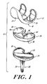
- Figure 1 is an exploded, perspective view of an artificial knee joint illustrating the femoral component, tibial plateau and the tibial bearing member.
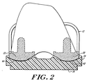
- Figure 2 is an anterior view of an artificial knee femoral component positioned adjacent a prosthetic tibial bearing member, in a condition of perfect alignment.
- Figure 3 is a side view from the medial side of an artificial knee femoral component positioned adjacent a prosthetic tibial bearing member, in perfect alignment.
- Figure 4 is a top view of the prosthetic tibial bearing member shown in Figure 1.
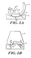
- Figure 5A is a sectional view, in the sagittal plane, of a femoral component and tibial bearing member constructed according to the present invention.
- Figure 5B is a partial sectional view, in the coronal plane, of a femoral component and tibial bearing member constructed according to the present invention.
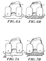
- Figure 6A is a posterior view of a prior art femoral component mounted adjacent a prior. art tibial bearing member in perfect alignment.
- Figure 6B is a posterior view of the femoral component of the present invention mounted adjacent the tibial bearing member of the present invention in perfect alignment.
- Figure 7A is a posterior view of a prior art femoral component mounted adjacent a prior art tibial bearing member in a malalignment condition having approximately 3° varus-valgus lift.
- Figure 7B is a posterior view of a femoral component of the present invention mounted adjacent a tibial bearing member of the present invention in a malalignment condition having 3° varus-valgus lift.
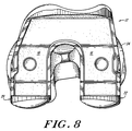
- Figure 8 is a top view of a femoral component of the present invention mounted adjacent to a tibial bearing member, in a malalignment condition having 8° internal-external rotation.
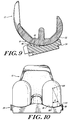
- Figure 9 is a side view (from the medial side) of the femoral component of the present invention mounted adjacent to a tibial bearing member at 15° flexion.
- Figure 10 is a posterior view of a femoral component constructed according to the present invention.
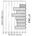
- Figure 11 is a bar graph illustrating the contact stresses that result during the engagement of a prosthetic femoral component with a tibial bearing member, in perfect alignment, for the artificial knee joint of the present invention and various prior art artificial knee joint designs.
- Figure 12 is a bar graph illustrating the contact stresses that result during the engagement of a prosthetic femoral component with a tibial bearing member in malalignment conditions for the artificial knee joint of the present compared to various prior art artificial knee joint designs.
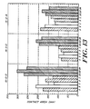
- Figure 13 is a bar graph illustrating the contact area of the engagement between prosthetic femoral components and prosthetic tibial bearing members of artificial knee joints constructed according to the present invention as compared to various prior art artificial knee joint constructions in different conditions of alignment.
- the present invention provides an improved construction for a knee joint prosthesis.
- the design and the geometry of the knee joint prosthesis of the invention facilitates greater contact between the femoral and tibial components of the knee joint prosthesis. This improved contact increases contact area and reduces contact stress between the articulation surfaces of the artificial joint and accordingly helps to eliminate or greatly reduce the tendency for wear debris to develop within a replaced joint.
- FIG. 1 illustrates three components found in a knee joint prosthesis 10 constructed according to the present invention.
- a femoral component 12 includes an inferior surface 16 which is mountable within the distal end of a patient's femur and a superior articulation surface 18.
- the articulation surface 18 includes adjacent lateral 20 and medial 22 condyles.
- the knee prosthesis 10 also includes a tibial tray or plateau 24, the distal end 26 of which includes a distally extending stem 25 which is mountable within the tibia of a patient.
- the proximal end 30 of the tibial plateau includes a recessed region 32 within which a tibial bearing member 34 is mounted in a mechanical fit.
- Tibial bearing member 34 includes a distal surface 36 mountable within a recessed region 32 of proximal end 30 of tibial plateau 24.
- the proximal surface 38 of tibial bearing member 34 forms an articulation surface 40 that engages and articulates with the articulation surface 18 of femoral component 12.
- the articulation surface 40 of the tibial bearing member 34 includes adjacent lateral 42 and medial 44 condyles. As shown in Figure 2, the lateral and medial condyles 20, 22 of the femoral component 12 mount in engagement with the lateral and medial condyles 42, 44 of tibial bearing member 34.
- a tibial component of an artificial knee joint can be formed as a single piece which includes portions that correspond to tibial tray component 24 and tibial bearing member 34.
- such single piece units are manufactured of ultrahigh molecular weight polyethylene.
- the condyles 20, 22 of femoral component 12 and the condyles 42, 44 of tibial bearing member 34 are configured such that when the condyles of these two components engage each other the contact area between the condyles of the femoral component and the condyles of the tibial bearing member is maximized.
- Greatest contact area is achieved in conditions of perfect alignment, throughout the range of motion of the knee joint, and in conditions of malalignment, including varus-valgus lift and internal-external rotation.
- perfect alignment refers to a condition where the knee joint is subjected to 0° varus-valgus lift, and 0° internal-external rotation throughout the anatomic range of flexion-extension (i.e., about -10° to 135°).
- the ability to achieve a large contact area between the condyles of the femoral component and the tibial bearing member is significant because contact stress on the prosthesis components, particularly the tibial bearing member, is minimized.
- the tibial bearing members are manufactured of polymeric materials, such as ultra-high molecular weight polyethylene (UHMWPE). Where loads are unevenly distributed or concentrated across the tibial bearing member during use of an artificial knee joint, edge loading can develop. Edge loading leads to the development of higher contact stresses in certain parts of the prosthesis which, in turn, can cause wear debris to develop within the joint.
- UHMWPE ultra-high molecular weight polyethylene
- FIGs 2, 3, 5A, 5B and 11 illustrate the femoral component 12 of the present invention, including condyles 20, 22.
- Each condyle 20, 22 is generally ellipsoid in shape and is of a curved, convex shape in both the anterior-posterior direction and the medial-lateral direction.
- the curvature of the articulation surface 23 of each condyle 20, 22 lying in the sagittal plane, in contact with the condyles 42, 44 of the tibial bearing member, and extending in the anterior-posterior direction is defined by at least two semi-parallel radii wherein a first sagittal radius is more anterior than a second sagittal radius.
- the first, more anterior sagittal radius (R 1 ) is offset from the second sagittal radius (R 2 ) by the distance between their respective centers of curvature (C 1 , C 2 ).
- the curvature of the articulation surface 23 lying in the sagittal plane for each condyle 20, 22 can be defined by approximately four radii.
- the critical surface geometry is that which relates to the portion of the condyles 20, 22 which contact the condyles 42, 44 of the tibial bearing member 34.
- a first sagittal radius (R 1 ) covers an intermediate portion of the articulation surface 23 of each condyle 20, 22 in the sagittal plane along the anterior-posterior direction.
- the articulation surface 23 of condyles 20, 22 defined by R 1 contacts the articulation surface 40 of tibial bearing member 34 during flexion of the knee between approximately 0° and 40°.
- the first sagittal radius (R 1 ) is in the range of approximately 1.020 to 1.885 inches.
- the second sagittal radius (R 2 ) covers a more posterior portion of the articulation surface 23 of condyles 20, 22 lying in the sagittal plane and extending in the anterior-posterior direction.
- the articulation surface 23 of condyles 20, 22 defined by R 2 typically contacts the articulation surface 40 of tibial bearing member 34 during flexion of the knee greater than about 40°.
- the second sagittal radius (R 2 ) preferably has a value of approximately 0.6 to 1.2 inches, and more preferably, due to anatomic constraints, of about 0.7 to 1.1 inches.
- the first and second sagittal radii originate from their respective centers of curvature (C 1 , C 2 ).
- the centers of curvature C 1 and C 2 are collinear and the center of curvature for R 2 (C 2 ) is more posterior than the center of curvature for R 1 (C 1 ).
- first and second sagittal radii are, to some extent, dependent upon the size of the femoral component.
- femoral components are available in different sizes to accommodate the anatomies of different patients.
- Femoral components can have dimensions in which the largest width (in the anterior-posterior dimension) ranges from about 50 to 74 mm, and in which the largest width (in the medial-lateral dimension) ranges from about 54 to 78 mm.
- Table 1 illustrates approximate values for the first and second sagittal radii with varying femoral component sizes.
- Figure 5B illustrates the curvature of articulation surface 23 of condyles 20, 22 lying in the coronal plane and extending in the medial-lateral direction.
- the curvature of this surface is defined by the coronal radius (R 3 ).
- the coronal radius is in the range of about 0.7 to 1.1 inches.
- the value of the coronal radius is substantially constant, and is not dependent on the size of the femoral component of the prosthesis. Thus, substantially the same coronal radius can be used without regard to the size of femoral component or tibial bearing member used.
- tibial bearing member 34 includes adjacent lateral 42 and medial 44 tibial condylar elements that are generally ellipsoid and are configured to seat on and articulate with condyles 20, 22 of femoral component 12.
- the tibial condylar elements 42, 44 preferably are of a curved, concave shape.
- the articulation surface 46 of tibial condylar elements 42, 44 is characterized by a curved, concave surface in both the medial-lateral and anterior-posterior directions.
- the curvature of the tibial condylar elements 42, 44 lying in the sagittal plane and extending in the anterior-posterior direction is defined by a sagittal radius (R s ).
- this radius is approximately 104% to 120% of the first sagittal radius (R 1 ) of the condylar elements 20, 22 of femoral component 12.
- the curvature of the condyles 42, 44 of the tibial bearing member 34 lying in the coronal plane and extending in the medial-lateral direction is defined by a coronal radius (R c ).
- the coronal radius of the condyles 42, 44 of the tibial bearing member preferably is approximately 120% to 152% of the coronal radius (R 3 ) of the condyles 20, 22 of the femoral component 12.
- the arc angle of the femoral component 12 of the prostheses of the present invention is dependent on the size of the femoral component.
- the arc angle ( ⁇ ), as illustrated in Figure 10, is the angle between a line drawn from the arc center 100 to the lowest point 102 on the articulation surface 18 and a line drawn between the arc center 100 and the lateral edge 28 of the articulation surface 23.
- the arc angle is directly proportional to the amount of varus-valgus lift that is allowable without incurring edge loading. Further, the arc angle is significant because it accommodates the effects of size and shape of condyles, allowing the condyles of the femoral and tibial components to achieve a suitable fit despite identically "matching" sizes not being used.
- the arc angle is size dependent since it is largely a function of the width of the femoral component 12 and the medial-lateral dimension.
- Table 2 illustrates representative arc angles for femoral components of varying sizes.
- Table 2 Femoral Component Size Largest A-P Dimension Largest M-L Dimension Arc Angle 2 56 mm 60 mm 21° 3 61 mm 66 mm 31° 4 65 mm 71 mm 40° 5 69 mm 73 mm 44° 6 74 mm 78 mm 45°
- the knee joint prosthesis 10 of the present invention provides many advantages. As noted above, the contact area between the femoral component 12 and the tibial bearing member 34 is maximized and contact stress is reduced. Another advantage, however, is that the femoral component of the knee joint prosthesis of this invention can be matched, during surgical implantation procedures, to a tibial bearing member that is of a corresponding size or one that is one size unit larger or smaller. This enables a surgeon to implant an artificial joint to accommodate anatomical needs of a patient. Despite such size mismatching, the knee prostheses of the invention still possess superior contact area and minimized contact stress.
- Figures 6A and 7A illustrate a known, prior art knee prosthesis in perfect alignment condition (Figure 6A) and when subjected to malalignment due to 3° varus-valgus lift (Figure 7A).
- the lateral condyle 20 of the femoral component 12 separates from the lateral condylar element 42 of the tibial bearing member 34.
- the interface of the lateral femoral condyle 20 and the lateral tibial condylar element 42 is subjected to edge loading.
- 3° varus-valgus malalignment of the knee prosthesis of the present invention shown in Figure 7B, maintains good contact between the femoral component and tibial bearing member articulation surfaces 18, 40 without edge loading.
- Figure 8 illustrates a femoral component 12 and a tibial bearing member 34 of the present invention mounted together and subjected to a malalignment condition of 8° internal/external rotation. Despite this malalignment, little or no edge loading occurs and good contact is maintained between the articulation surfaces of femoral component 12 and tibial bearing member 34.
- Figure 9 illustrates the femoral component 12 of the present invention mounted adjacent the tibial bearing member 34 of the present invention during 15° flexion of the knee joint. As illustrated, good contact is maintained between the articulation surfaces of the femoral component 12 and the tibial bearing member 34 during such flexion.
- Figure 11 illustrates observed values of contact stress between the articulation surfaces of a femoral component and a tibial bearing member for a variety of prior art knee prostheses (samples A through G), including the knee prosthesis of the present invention (sample X).
- contact stress was evaluated for a knee prosthesis in an alignment condition of 15° flexion, 3° varus-valgus lift, and 0° internal-external rotation when subjected to a load of about 2060 N, approximately three times average body weight.
- the experimental protocol required that the femoral components be cemented to an appropriate holding block by forcing the femoral component onto the block (which bears a cement) until the femoral component can move no further.
- Tibial trays are then cemented onto tibial holding blocks.
- a rotary indexing table is then fastened onto a x-y plate which is bolted to an Instron 1123 tensile compressive mechanical testing machine. The rotary indexing table is leveled and shimmed, if necessary. This apparatus is attached to the Instron 1123 in an orientation rotated approximately 45° clockwise from the anterior forward position.
- the femoral test block is then fastened to a femoral block holding bracket and this assembly is screwed into the load cell of the Instron 1123.
- the tibial holding block is bolted onto the base plate of the rotary indexing table.
- the femoral assembly (without the femoral components attached) is placed against the tibial holding block.
- the femoral assembly should be adjusted such that the tibial holding block is perpendicular to the femoral block holder. (The rotary dial is not used in the alignment process.)
- the tibial inserts Prior to testing, the tibial inserts are soaked in a water bath (37°C ⁇ 1°C) for about 18-24 hours. The tests are conducted within an environmental chamber which is at a temperature of 37°C + 1°C and at 80 - 90% relative humidity. When the chamber reaches the desired temperature and humidity levels, the tibial insert is removed from the bath and inserted into the tibial holding fixture. During testing the femoral component can be set at a desired flexion angle.
- the prosthesis of the present invention exhibited peak contact stress well below that of prior art knee prostheses.
- the knee prosthesis of the present invention displayed contact stress of approximately 11 MPa, while contact stress for prior art knee prostheses ranged from 16 to 24 MPa.
- Figure 12 shows the results of an evaluation of the peak contact stress, using the same test method used to generate the data of Figure 11, except that the knee prostheses were in a malalignment condition of 15° flexion, 3° varus-valgus lift, and 0° internal-external rotation.
- the present knee prosthesis demonstrated contact stress of approximately 16 MPa while contact stress developed using prior art knee prosthesis ranged from approximately 24 MPa to 30 MPa, as shown in Figure 12.
- Figure 13 illustrates data obtained while comparing the contact area between femoral and tibial components of various knee prostheses in three different alignment conditions.
- the alignment conditions evaluated were 15° flexion, 0° varus-valgus lift, and 0° internal/external rotation (15-0-0); 15° flexion, 3° varus-valgus lift, and 0° internal/external rotation (15-3-0); and 15° flexion, 0° varus-valgus lift, and 8° internal/external rotation (15-0-8).
- the data shown in Figure 13 was also generated using the procedure described above as the TEKSCAN technology provides both contact area and contact stress in defined areas of a knee joint prosthesis.
- Samples of the present invention are designated as samples 3/2, 3/3, and 3/4.
- the first numeral refers to femoral component size, as defined in table 1 and 2
- the second numeral refers to tibial bearing member size.
- the contact area between femoral and tibial components of various knee prostheses in the 15-0-0 alignment condition, illustrated in Figure 13, established that knee joints of the present invention (samples 3/2, 3/3, and 3/4) demonstrated significantly higher contact area than did the prior art knee prostheses evaluated.
- a knee prosthesis of the present invention using a size 3 femoral component (61 x 66 mm) and a size 3 tibial bearing member (47 x 71 mm) (sample 3/3) demonstrated a contact area of approximately 270 mm 2 .
- a size 3 femoral component matched with a size 2 tibial bearing member (43 x 64 mm) (sample 3/2) achieved contact area of approximately 310 mm 2 .
- prior art knee prostheses demonstrated contact areas ranging from approximately 120 to 210 mm 2 in the 15-0-0 alignment condition.
- Figure 13 also illustrates that the contact area of three knee prostheses size configurations according to the present invention (3/3, 3/2 and 3/4) achieved contact areas of 190 mm 2 , 210 mm 2 , and 170 mm 2 , respectively, when the knee joint was subjected to a 15-3-0 malalignment condition
- Other knee prostheses evaluated had contact areas that ranged from approximately 70 to 97 mm 2 under the same test conditions.
- the three knee prosthesis size configurations of the present invention (3/3, 3/2, and 3/4) also demonstrated relatively high contact area when subjected to a 15-0-8 malalignment condition
- the knee prostheses of the present invention exhibited contact of 170 mm 2 for the 3/3 size configuration, 185 mm 2 for the 3/2 size configuration, and 147 for the 3/4 size configuration.
- the prior art knee prostheses evaluated exhibited contact area ranging from about 119 to 190mm 2 under the same conditions.
- the design and geometry of the articulation surfaces of the femoral component and tibial bearing member of the knee prostheses made according to the present invention lends itself to use with a variety of different constructions for a knee joint prostheses. That is, the articulation surface design and geometry described herein may be incorporated to knee joint prostheses such as cruciate retaining knee prostheses, cruciate sacrificing knee prostheses, meniscal bearing prostheses, hinge prostheses, and unicondylar prostheses.
- the knee prostheses of the invention can be made from a variety of biocompatible materials having high strength, durability and resistance to wear debris.
- materials include metal alloys such as cobalt-chromium alloy, titanium-aluminum-vanadium alloy, stainless steel, ceramics, and other materials that are well known for use in the manufacture of implantable bone prostheses.
- the femoral component and tibial plateau are made from metal alloys such as cobalt-chromium alloy while the tibial bearing member is made from polymers such as ultra-high molecular weight polyethylene.
Abstract
Description
- The invention relates to implantable bone prostheses, and more particularly to knee joint prostheses.
- Joint replacement surgery is quite common and enables many individuals to function normally when otherwise it would not be possible to do so. Artificial joints are normally composed of metallic and/or ceramic components that are fixed to existing bone.
- Knee arthroplasty is a well known surgical procedure by which a diseased and/or damaged natural knee joint is replaced with a prosthetic knee joint. Typical knee prostheses include a femoral component, a patella component, a tibial tray or plateau, and a tibial bearing member. The femoral component generally includes a pair of laterally spaced apart condylar portions, the inferior or distal surfaces of which articulate with complementary condylar elements formed in a tibial bearing component.
- In a properly functioning artificial knee joint, the condylar portions of the femoral component must slide and roll freely over the articulation surface formed by the condylar elements of the tibial bearing member. Natural friction within a replaced, artificial joint can lead to the development of wear debris in which minute particles of debris (e.g., metal or plastic from the prosthesis) become dislodged and migrate within the joint. The phenomenon of wear debris within artificial joints is a serious problem that can inhibit the proper mechanical functioning of the joint. Moreover, wear debris can lead to osteolysis and bone deterioration. When wear debris develops within an artificial joint, surgical removal of the debris or subsequent replacement of the artificial joint is often necessary.
- During normal usage of a properly implanted prosthetic knee joint, load and stress are placed on the tibial bearing member. The tibial bearing member is typically made of an ultrahigh molecular weight polyethylene (UHMWPE), and friction, continuous cycling and stress can cause some erosion and/or fracture of the tibial bearing member, thus leading to wear debris. The risk of wear debris can be even greater during malalignment of an artificial knee joint, which can result from normal usage or from imperfect and/or inaccurate implantation of the prosthesis within a patient. During malalignment the load upon the tibial bearing member is not evenly distributed. Instead, excess load is placed on certain areas of the tibial bearing member. This uneven distribution of load (or edge loading) can accelerate the development of wear debris. Contact stresses on the tibial bearing member increase substantially with malalignment of the joint, thus increasing the risk that wear debris will develop when a prosthetic knee joint is subjected to malalignment conditions.
- Joint replacement surgery obviously requires a tremendous degree of precision to ensure that prosthetic components are properly sized, implanted, and aligned. Imperfect sizing, implantation and alignment can lead to inadequate performance of the knee joint as well as to the presence of high contact stresses in certain areas of the prosthesis, thus leading to the possible development of wear debris.
- The anatomy of patients who undergo knee arthroplasty is widely variable and can lead to difficulty in matching the standard sized prosthetic components that form a prosthetic joint. Many prosthetic components are manufactured such that similarly sized components must be used together and implanted within a patient when replacing a natural joint. That is, the femoral component, tibial bearing member, and tibial plateau that form the artificial knee joint must normally be of a matched size. If the components are not size-matched, inappropriate edge loading may develop and accelerate wear.
- There is thus a need for knee joint prostheses that have a reduced tendency to develop wear debris due to the maintenance of good contact area and low contact stress between femoral and tibial components, even during the dynamics of daily activity and in various conditions of malalignment, with the options of matched or mismatched condylar sizes.
- Accordingly, it is an object of the present invention to provide knee joint prostheses with improved performance and a longer useful life. It is also an object of the invention to provide knee joint prostheses having a reduced tendency to develop wear debris. A further object of the invention is to provide knee joint prostheses which are able to maintain good contact area and low contact stress between femoral and tibial components throughout normal usage conditions and in conditions of malalignment. Another object of the invention is to provide knee joint prostheses that enable the mixing of component sizes while still maintaining low contact stresses between femoral and tibial components. These and other objects will be apparent from the description that follows.
- The invention provides a knee joint prosthesis in which the articulation surfaces of the femoral and tibial components are configured to maintain good contact area and low contact stress when implanted in a patient. The femoral component of the knee joint prosthesis has a proximal surface which is mountable on a distal end of the femur of a patient, and a distal articulation surface that includes two adjacent, semi-parallel bearing surfaces that form femoral condyles. Each femoral condyle is of a curved, convex shape in both the anterior-posterior direction and in the medial-lateral direction. The curvature of each femoral condyle lying in the sagittal plane, in contact with a tibial condylar element, and extending in the anterior-posterior direction is defined by at least two semi-parallel radii wherein a first sagittal radius is more anterior than a second sagittal radius with the first and second sagittal radii being offset from one another by the distance between their respective centers of curvature. Preferably, the centers of curvature of the first and second sagittal radii are colinear. The curvature of each femoral condyle lying in the coronal plane, in contact with a tibial condylar element, and extending in the medial-lateral direction is defined by a coronal radius.
- The prosthesis also includes a tibial tray or plateau having a proximal end and a distal end that is mountable on the tibia of the patient. Further, the prosthesis includes a tibial bearing member having a distal surface mountable within the proximal end of the tibial plateau component and a proximal articulation surface. The proximal articulation surface of the tibial bearing member includes two adjacent tibial condylar elements that seat the adjacent, semi-parallel bearing surfaces of the femoral component. Each condylar element of the tibial bearing member is of a curved, concave shape in both the anterior-posterior and medial-lateral directions.
- The prosthesis of the present invention is characterized by improved contact between the femoral condyles and the tibial condylar elements. Preferably, contact stress between the femoral bearing surfaces and the condylar elements, when subjected to a load of approximately 2060 N, does not exceed approximately 15 MPa when the prosthesis is in perfect alignment and do not exceed approximately 20 MPa when the prosthesis is subjected to varus-valgus lift and internal-external rotation conditions of malalignment. Further, the contact area between the condyles of the femoral component and the condylar elements of the tibial bearing member, when the prosthesis is subjected to approximately 15° flexion, without malalignment, is greater than 200 mm2. The contact area between the condyles of the femoral component and the condylar elements of the tibial bearing member, when the prosthesis is subjected to approximately to 15° flexion and 3° varus-valgus lift, is greater than 130 mm2.
- Preferably, the first and second sagittal radii increase with increasing size of the femoral component of the prosthesis while the coronal radius remains substantially constant with increasing sizes of the femoral component. The first sagittal radius is in the range of about 1.020 to 1.885 inches while the second sagittal radius is in the range of about 0.6 to 1.2 inches. The coronal radius preferably is in the range of about 0.7 to 1.1 inches.
- The curvature of the tibial condylar elements, in the anterior-posterior direction, is defined by a radius that is approximately 104% to 120% of the first sagittal radius of the bearing surfaces of the femoral component. The curvature of the tibial condylar elements, in the medial-lateral direction, is defined by a radius that is approximately 120% to 152% of the coronal radius of the bearing surfaces of the femoral component.
- Figure 1 is an exploded, perspective view of an artificial knee joint illustrating the femoral component, tibial plateau and the tibial bearing member.
- Figure 2 is an anterior view of an artificial knee femoral component positioned adjacent a prosthetic tibial bearing member, in a condition of perfect alignment.
- Figure 3 is a side view from the medial side of an artificial knee femoral component positioned adjacent a prosthetic tibial bearing member, in perfect alignment.
- Figure 4 is a top view of the prosthetic tibial bearing member shown in Figure 1.
- Figure 5A is a sectional view, in the sagittal plane, of a femoral component and tibial bearing member constructed according to the present invention.
- Figure 5B is a partial sectional view, in the coronal plane, of a femoral component and tibial bearing member constructed according to the present invention.
- Figure 6A is a posterior view of a prior art femoral component mounted adjacent a prior. art tibial bearing member in perfect alignment.
- Figure 6B is a posterior view of the femoral component of the present invention mounted adjacent the tibial bearing member of the present invention in perfect alignment.
- Figure 7A is a posterior view of a prior art femoral component mounted adjacent a prior art tibial bearing member in a malalignment condition having approximately 3° varus-valgus lift.
- Figure 7B is a posterior view of a femoral component of the present invention mounted adjacent a tibial bearing member of the present invention in a malalignment condition having 3° varus-valgus lift.
- Figure 8 is a top view of a femoral component of the present invention mounted adjacent to a tibial bearing member, in a malalignment condition having 8° internal-external rotation.
- Figure 9 is a side view (from the medial side) of the femoral component of the present invention mounted adjacent to a tibial bearing member at 15° flexion.
- Figure 10 is a posterior view of a femoral component constructed according to the present invention.
- Figure 11 is a bar graph illustrating the contact stresses that result during the engagement of a prosthetic femoral component with a tibial bearing member, in perfect alignment, for the artificial knee joint of the present invention and various prior art artificial knee joint designs.
- Figure 12 is a bar graph illustrating the contact stresses that result during the engagement of a prosthetic femoral component with a tibial bearing member in malalignment conditions for the artificial knee joint of the present compared to various prior art artificial knee joint designs.
- Figure 13 is a bar graph illustrating the contact area of the engagement between prosthetic femoral components and prosthetic tibial bearing members of artificial knee joints constructed according to the present invention as compared to various prior art artificial knee joint constructions in different conditions of alignment.
- The present invention provides an improved construction for a knee joint prosthesis. The design and the geometry of the knee joint prosthesis of the invention facilitates greater contact between the femoral and tibial components of the knee joint prosthesis. This improved contact increases contact area and reduces contact stress between the articulation surfaces of the artificial joint and accordingly helps to eliminate or greatly reduce the tendency for wear debris to develop within a replaced joint.
- Figure 1 illustrates three components found in a knee
joint prosthesis 10 constructed according to the present invention. Afemoral component 12 includes aninferior surface 16 which is mountable within the distal end of a patient's femur and asuperior articulation surface 18. Thearticulation surface 18 includesadjacent lateral 20 and medial 22 condyles. Theknee prosthesis 10 also includes a tibial tray orplateau 24, thedistal end 26 of which includes adistally extending stem 25 which is mountable within the tibia of a patient. Theproximal end 30 of the tibial plateau includes a recessedregion 32 within which atibial bearing member 34 is mounted in a mechanical fit. -
Tibial bearing member 34 includes adistal surface 36 mountable within a recessedregion 32 ofproximal end 30 oftibial plateau 24. Theproximal surface 38 oftibial bearing member 34 forms anarticulation surface 40 that engages and articulates with thearticulation surface 18 offemoral component 12. Thearticulation surface 40 of thetibial bearing member 34 includesadjacent lateral 42 and medial 44 condyles. As shown in Figure 2, the lateral andmedial condyles femoral component 12 mount in engagement with the lateral andmedial condyles tibial bearing member 34. - Although not illustrated, it is understood that a tibial component of an artificial knee joint can be formed as a single piece which includes portions that correspond to
tibial tray component 24 andtibial bearing member 34. Typically, such single piece units are manufactured of ultrahigh molecular weight polyethylene. - The
condyles femoral component 12 and thecondyles tibial bearing member 34 are configured such that when the condyles of these two components engage each other the contact area between the condyles of the femoral component and the condyles of the tibial bearing member is maximized. Greatest contact area is achieved in conditions of perfect alignment, throughout the range of motion of the knee joint, and in conditions of malalignment, including varus-valgus lift and internal-external rotation. The term "perfect alignment", as used herein refers to a condition where the knee joint is subjected to 0° varus-valgus lift, and 0° internal-external rotation throughout the anatomic range of flexion-extension (i.e., about -10° to 135°). - The ability to achieve a large contact area between the condyles of the femoral component and the tibial bearing member is significant because contact stress on the prosthesis components, particularly the tibial bearing member, is minimized. In many instances, the tibial bearing members are manufactured of polymeric materials, such as ultra-high molecular weight polyethylene (UHMWPE). Where loads are unevenly distributed or concentrated across the tibial bearing member during use of an artificial knee joint, edge loading can develop. Edge loading leads to the development of higher contact stresses in certain parts of the prosthesis which, in turn, can cause wear debris to develop within the joint.
- Figures 2, 3, 5A, 5B and 11 illustrate the
femoral component 12 of the present invention, includingcondyles condyle articulation surface 23 of eachcondyle condyles - As shown in Figure 5A, the curvature of the
articulation surface 23 lying in the sagittal plane for eachcondyle condyles condyles tibial bearing member 34. A first sagittal radius (R1) covers an intermediate portion of thearticulation surface 23 of eachcondyle articulation surface 23 ofcondyles articulation surface 40 oftibial bearing member 34 during flexion of the knee between approximately 0° and 40°. The first sagittal radius (R1) is in the range of approximately 1.020 to 1.885 inches. - The second sagittal radius (R2) covers a more posterior portion of the
articulation surface 23 ofcondyles articulation surface 23 ofcondyles articulation surface 40 oftibial bearing member 34 during flexion of the knee greater than about 40°. The second sagittal radius (R2) preferably has a value of approximately 0.6 to 1.2 inches, and more preferably, due to anatomic constraints, of about 0.7 to 1.1 inches. - As illustrated in Figure 5A, the first and second sagittal radii (R1, R2) originate from their respective centers of curvature (C1, C2). The centers of curvature C1 and C2 are collinear and the center of curvature for R2 (C2) is more posterior than the center of curvature for R1 (C1).
- The values of first and second sagittal radii (R1, R2) are, to some extent, dependent upon the size of the femoral component. Typically, femoral components are available in different sizes to accommodate the anatomies of different patients. Femoral components can have dimensions in which the largest width (in the anterior-posterior dimension) ranges from about 50 to 74 mm, and in which the largest width (in the medial-lateral dimension) ranges from about 54 to 78 mm. Table 1 illustrates approximate values for the first and second sagittal radii with varying femoral component sizes.
Table 1 Femoral Component Size A-P Width (mm) M-L Width (mm) R 1 Value (inches) R 2 Value (inches) 2 56 60 1.194 0.743 3 61 66 1.321 0.794 4 65 71 1.405 0.828 5 69 73 1.511 0.860 6 74 78 1.750 0.950 - Figure 5B illustrates the curvature of
articulation surface 23 ofcondyles - Referring to Figures 1 through 4, 10A and 10B, tibial bearing
member 34 includesadjacent lateral 42 and medial 44 tibial condylar elements that are generally ellipsoid and are configured to seat on and articulate withcondyles femoral component 12. The tibialcondylar elements condylar elements condylar elements condylar elements femoral component 12. - The curvature of the
condyles tibial bearing member 34 lying in the coronal plane and extending in the medial-lateral direction is defined by a coronal radius (Rc). The coronal radius of thecondyles condyles femoral component 12. - The arc angle of the
femoral component 12 of the prostheses of the present invention is dependent on the size of the femoral component. The arc angle (α), as illustrated in Figure 10, is the angle between a line drawn from thearc center 100 to thelowest point 102 on thearticulation surface 18 and a line drawn between thearc center 100 and thelateral edge 28 of thearticulation surface 23. The arc angle is directly proportional to the amount of varus-valgus lift that is allowable without incurring edge loading. Further, the arc angle is significant because it accommodates the effects of size and shape of condyles, allowing the condyles of the femoral and tibial components to achieve a suitable fit despite identically "matching" sizes not being used. - The arc angle is size dependent since it is largely a function of the width of the
femoral component 12 and the medial-lateral dimension. Table 2 illustrates representative arc angles for femoral components of varying sizes.Table 2 Femoral Component Size Largest A-P Dimension Largest M-L Dimension Arc Angle 2 56 mm 60 mm 21° 3 61 mm 66 mm 31° 4 65 mm 71 mm 40° 5 69 mm 73 mm 44° 6 74 mm 78 mm 45° - The knee
joint prosthesis 10 of the present invention provides many advantages. As noted above, the contact area between thefemoral component 12 and thetibial bearing member 34 is maximized and contact stress is reduced. Another advantage, however, is that the femoral component of the knee joint prosthesis of this invention can be matched, during surgical implantation procedures, to a tibial bearing member that is of a corresponding size or one that is one size unit larger or smaller. This enables a surgeon to implant an artificial joint to accommodate anatomical needs of a patient. Despite such size mismatching, the knee prostheses of the invention still possess superior contact area and minimized contact stress. - Figures 6A and 7A illustrate a known, prior art knee prosthesis in perfect alignment condition (Figure 6A) and when subjected to malalignment due to 3° varus-valgus lift (Figure 7A). As illustrated, the
lateral condyle 20 of thefemoral component 12 separates from thelateral condylar element 42 of thetibial bearing member 34. As a result, the interface of the lateralfemoral condyle 20 and the lateraltibial condylar element 42 is subjected to edge loading. By comparison, 3° varus-valgus malalignment of the knee prosthesis of the present invention, shown in Figure 7B, maintains good contact between the femoral component and tibial bearing member articulation surfaces 18, 40 without edge loading. - Figure 8 illustrates a
femoral component 12 and atibial bearing member 34 of the present invention mounted together and subjected to a malalignment condition of 8° internal/external rotation. Despite this malalignment, little or no edge loading occurs and good contact is maintained between the articulation surfaces offemoral component 12 andtibial bearing member 34. - Figure 9 illustrates the
femoral component 12 of the present invention mounted adjacent thetibial bearing member 34 of the present invention during 15° flexion of the knee joint. As illustrated, good contact is maintained between the articulation surfaces of thefemoral component 12 and thetibial bearing member 34 during such flexion. - Figure 11 illustrates observed values of contact stress between the articulation surfaces of a femoral component and a tibial bearing member for a variety of prior art knee prostheses (samples A through G), including the knee prosthesis of the present invention (sample X). To generate the data shown in Figure 11, contact stress was evaluated for a knee prosthesis in an alignment condition of 15° flexion, 3° varus-valgus lift, and 0° internal-external rotation when subjected to a load of about 2060 N, approximately three times average body weight.
- The experimental protocol required that the femoral components be cemented to an appropriate holding block by forcing the femoral component onto the block (which bears a cement) until the femoral component can move no further. Tibial trays are then cemented onto tibial holding blocks. A rotary indexing table is then fastened onto a x-y plate which is bolted to an Instron 1123 tensile compressive mechanical testing machine. The rotary indexing table is leveled and shimmed, if necessary. This apparatus is attached to the Instron 1123 in an orientation rotated approximately 45° clockwise from the anterior forward position.
- The femoral test block is then fastened to a femoral block holding bracket and this assembly is screwed into the load cell of the Instron 1123. Next, the tibial holding block is bolted onto the base plate of the rotary indexing table. The femoral assembly (without the femoral components attached) is placed against the tibial holding block. The femoral assembly should be adjusted such that the tibial holding block is perpendicular to the femoral block holder. (The rotary dial is not used in the alignment process.)
- Prior to testing, the tibial inserts are soaked in a water bath (37°C ±1°C) for about 18-24 hours. The tests are conducted within an environmental chamber which is at a temperature of 37°C + 1°C and at 80 - 90% relative humidity. When the chamber reaches the desired temperature and humidity levels, the tibial insert is removed from the bath and inserted into the tibial holding fixture. During testing the femoral component can be set at a desired flexion angle.
- At the outset of testing a crosshead speed of 2 mm/minute, with a 500kg full scale setting on the Instron chart recorder, is set. An interpositional film having an electrode sensor grid, such as TEKSCAN, available from Tekscan, Inc. of Boston, Massachusetts is then placed between the femoral and tibial components. The real time screen is opened and the force calibration is performed. The sensor is placed between the femoral component and the tibial insert. Loading is ideally located at the center of the sensor grid. The TEKSCAN technology then prompts the user to enter the load value applied. Next, the femoral is loaded onto the tibil insert (and the TEKSCAN sensors). The load is allowed to increase until the appropriate level is reached. At that instant, the "stop" button on the Instron displacement controller and the "Enter" key on the PC keyboard are depressed simultaneously. The contact stress and contact area are recorded and the load is then removed.
- As illustrated, the prosthesis of the present invention exhibited peak contact stress well below that of prior art knee prostheses. The knee prosthesis of the present invention displayed contact stress of approximately 11 MPa, while contact stress for prior art knee prostheses ranged from 16 to 24 MPa.
- Figure 12 shows the results of an evaluation of the peak contact stress, using the same test method used to generate the data of Figure 11, except that the knee prostheses were in a malalignment condition of 15° flexion, 3° varus-valgus lift, and 0° internal-external rotation. The present knee prosthesis (sample X) demonstrated contact stress of approximately 16 MPa while contact stress developed using prior art knee prosthesis ranged from approximately 24 MPa to 30 MPa, as shown in Figure 12.
- Figure 13 illustrates data obtained while comparing the contact area between femoral and tibial components of various knee prostheses in three different alignment conditions. The alignment conditions evaluated were 15° flexion, 0° varus-valgus lift, and 0° internal/external rotation (15-0-0); 15° flexion, 3° varus-valgus lift, and 0° internal/external rotation (15-3-0); and 15° flexion, 0° varus-valgus lift, and 8° internal/external rotation (15-0-8). The data shown in Figure 13 was also generated using the procedure described above as the TEKSCAN technology provides both contact area and contact stress in defined areas of a knee joint prosthesis.
- Prior art knee joint samples are designated as samples A through E in Figure 13. Samples of the present invention are designated as samples 3/2, 3/3, and 3/4. In designating samples of the present invention, the first numeral refers to femoral component size, as defined in table 1 and 2, while the second numeral refers to tibial bearing member size.
- The contact area between femoral and tibial components of various knee prostheses, in the 15-0-0 alignment condition, illustrated in Figure 13, established that knee joints of the present invention (samples 3/2, 3/3, and 3/4) demonstrated significantly higher contact area than did the prior art knee prostheses evaluated. A knee prosthesis of the present invention, using a size 3 femoral component (61 x 66 mm) and a size 3 tibial bearing member (47 x 71 mm) (sample 3/3) demonstrated a contact area of approximately 270 mm2. A size 3 femoral component matched with a size 2 tibial bearing member (43 x 64 mm) (sample 3/2) achieved contact area of approximately 310 mm2. A size 3 femoral component matched with a size 4 tibial bearing member (51 x 76 mm2) (sample 3/4) achieved contact area of approximately 355 mm2. By comparison, prior art knee prostheses demonstrated contact areas ranging from approximately 120 to 210 mm2 in the 15-0-0 alignment condition.
- Figure 13 also illustrates that the contact area of three knee prostheses size configurations according to the present invention (3/3, 3/2 and 3/4) achieved contact areas of 190 mm2, 210 mm2, and 170 mm2, respectively, when the knee joint was subjected to a 15-3-0 malalignment condition Other knee prostheses evaluated had contact areas that ranged from approximately 70 to 97 mm2 under the same test conditions.
- The three knee prosthesis size configurations of the present invention (3/3, 3/2, and 3/4) also demonstrated relatively high contact area when subjected to a 15-0-8 malalignment condition The knee prostheses of the present invention exhibited contact of 170 mm2 for the 3/3 size configuration, 185 mm2 for the 3/2 size configuration, and 147 for the 3/4 size configuration. The prior art knee prostheses evaluated exhibited contact area ranging from about 119 to 190mm2 under the same conditions.
- The design and geometry of the articulation surfaces of the femoral component and tibial bearing member of the knee prostheses made according to the present invention lends itself to use with a variety of different constructions for a knee joint prostheses. That is, the articulation surface design and geometry described herein may be incorporated to knee joint prostheses such as cruciate retaining knee prostheses, cruciate sacrificing knee prostheses, meniscal bearing prostheses, hinge prostheses, and unicondylar prostheses.
- It will be appreciated by those of ordinary skill in art, that the knee prostheses of the invention can be made from a variety of biocompatible materials having high strength, durability and resistance to wear debris. Examples of such materials include metal alloys such as cobalt-chromium alloy, titanium-aluminum-vanadium alloy, stainless steel, ceramics, and other materials that are well known for use in the manufacture of implantable bone prostheses. Typically, the femoral component and tibial plateau are made from metal alloys such as cobalt-chromium alloy while the tibial bearing member is made from polymers such as ultra-high molecular weight polyethylene.
- The foregoing description of the invention is presented to indicate the range of constructions to which the invention applies. Variations in the physical architecture and dimensions of the knee prostheses will be apparent to those having ordinary skill in the art based upon the disclosure herein and such variations are considered to be within the scope of the invention in which patent rights are asserted, as set forth in the claims appended hereto.
Claims (14)
- A knee prosthesis, comprising:a femoral component having an inferior surface mountable on a distal end of the femur of a patient and a superior articulation surface including two adjacent, semi-parallel bearing surfaces, each bearing surface being of a curved, convex shape both in the anterior-posterior direction and in the medial-lateral direction, wherein the curvature of each bearing surface lying in the sagittal plane, in contact with a tibial condylar element, and extending in the anterior-posterior direction is defined by at least two semi-parallel radii wherein a first sagittal radius is more anterior than a second sagittal radius with the first and second sagittal radii being offset from one another by the distance between their respective centers of curvature, and wherein the curvature of each bearing surface lying in the coronal plane, in contact with a tibial condylar element, and extending in the medial-lateral direction is defined by a coronal radius;a tibial component having a proximal end and a distal end mountable on the tibia of a patient; anda tibial bearing member having a distal surface mountable within the proximal end of the tibial component and a proximal articulation surface, the proximal articulation surface including two adjacent tibial condylar elements that seat the adjacent, semi-parallel bearing surfaces of the femoral component, each condylar element being of a curved, concave shape in both the anterior-posterior and medial-lateral directions;the prosthesis being characterized by improved contact between the femoral bearing surfaces and the tibial condylar elements throughout the range of motion of a knee joint such that contact stress between the bearing surfaces of the femoral component and the condylar elements of the tibial bearing member, when subject to a load of approximately 2060 N, does not exceed approximately 15 MPa when the prosthesis is in perfect alignment and does not exceed approximately 20 MPa when the prosthesis is subjected to varus-valgus lift and/or internal-external rotation conditions of malalignment.
- The prosthesis of claim 1 wherein the first and second sagittal radii increase with increasing size of the femoral component of the prosthesis.
- The prosethesis of claim 1 or claim 2 wherein the first sagittal radius, in contact with the tibial condylar element, is in the range of about 1.020 to 1.885 inches.
- The prosthesis of any one of claims 1 to 3 wherein the second sagittal radius, in contact with the tibial condylar element, is in the range of about 0.7 to 1.1 inches.
- The prosthesis of any one of claims 1 to 4 wherein the coronal radius is substantially constant with increasing size of the femoral component of the prosthesis.
- The prosthesis of claim 5 wherein the coronal radius is in the range of about 0.7 to 1.1 inches.
- The prosthesis of any one of claims 1 to 6 wherein the contact area between the bearing surface of the femoral component and the condylar elements of the tibial bearing member, when the prosthesis is subjected to approximately 15° flexion without malalignment, is greater than 200 mm 2 .
- The prosthesis of any one of claims 1 to 6 wherein the contact area between the bearing surfaces of the femoral component and the condylar elements of the tibial bearing member, when the prosthesis is subjected to approximately 15° flexion and 3° varus-valgus lift, is greater than 130 mm 2 .
- The prosthesis of any one of claims 1 to 8 wherein femoral component can be matched, during surgical implantation procedures, with a tibial bearing member that is of a corresponding size, or a tibial bearing member that is one size unit larger or smaller than a corresponding size, without compromising performance of the prosthesis.
- The prosthesis of any one of claims 1 to 9 wherein the curvature of the tibial condylar elements, in the anterior-prosterior direction, is defined by a radius that is approximately 104% of the first sagittal radius of the bearing surfaces of the femoral component.
- The prosthesis of any one of claims 1 to 10 wherein the curvature of the tibial condylar elements, in the medial-lateral direction, is defined by a radius that is approximately 120% to 152% of the coronal radius of the bearing surfaces of the femoral component.
- The prosthesis of any one of claims 1 to 11 wherein the varus-valgus malalignment condition is 3° varus-valgus lift.
- The prosthesis of any one of claims 1 to 12 wherein the internal-external rotation malalignment condition is 8° internal-external rotation.
- A knee prosthesis, comprising:a femoral component having an inferior surface mountable on a distal end of the femur of a patient and a superior articulation surface including two adjacent, semi-parallel bearing surfaces, each bearing surface being of a curved, convex shape both in the anterior-posterior direction and in the medial-lateral direction, wherein the curvature of each bearing surface lying in the sagittal plane, in contact with a tibial condylar element, and extending in the anterior-posterior direction is defined by at least two sagittal radii wherein a first sagittal radius, more anterior than a second sagittal radius, is about 1.020 to 1.885 inches, and the second sagittal radius is about 0.7 to 1.1 inches, and wherein the curvature of each bearing surface lying in the coronal plane, in contact with a tibial condylar element, and extending in the medial-lateral direction is defined by a coronal radius of about 0.7 to 1.1 inches;a tibial component having a proximal end and a distal end mountable on the tibia of a patient; anda tibial bearing member having a distal surface mountable within the proximal end of the tibial component and a proximal articulation surface, the proximal articulation surface including two adjacent tibial condylar elements that seat the adjacent, semi-parallel bearing surfaces the femoral component, each condylar element being of a curved, concave shape in both the anterior-posterior and medial-lateral directions wherein the curvature of the condylar elements in the anterior-posterior direction is defined by a radius that is approximately 104% to 120% of the first sagittal radius and the curvature of the condylar elements in the medial-lateral direction is defined by a radius that is approximately 120% to 152% of the coronal radius of the bearing surfaces of the femoral component;the prosthesis being characterized by improved contact area and reduced contact stress between the femoral bearing surfaces and the tibial condylar elements throughout the range of motion of a knee joint and in conditions of malalignment.
Applications Claiming Priority (2)
| Application Number | Priority Date | Filing Date | Title |
|---|---|---|---|
| US404195 | 1995-03-13 | ||
| US08/404,195 US5609643A (en) | 1995-03-13 | 1995-03-13 | Knee joint prosthesis |
Publications (3)
| Publication Number | Publication Date |
|---|---|
| EP0732092A2 true EP0732092A2 (en) | 1996-09-18 |
| EP0732092A3 EP0732092A3 (en) | 1997-01-22 |
| EP0732092B1 EP0732092B1 (en) | 2002-02-13 |
Family
ID=23598574
Family Applications (1)
| Application Number | Title | Priority Date | Filing Date |
|---|---|---|---|
| EP96301666A Expired - Lifetime EP0732092B1 (en) | 1995-03-13 | 1996-03-12 | Knee joint prosthesis |
Country Status (8)
| Country | Link |
|---|---|
| US (1) | US5609643A (en) |
| EP (1) | EP0732092B1 (en) |
| JP (1) | JP3966427B2 (en) |
| KR (1) | KR100385827B1 (en) |
| AU (1) | AU714406B2 (en) |
| CA (1) | CA2171514C (en) |
| DE (1) | DE69619145T2 (en) |
| ES (1) | ES2171610T3 (en) |
Cited By (15)
| Publication number | Priority date | Publication date | Assignee | Title |
|---|---|---|---|---|
| DE19708375A1 (en) * | 1997-01-17 | 1998-07-23 | Ceramtec Ag | Fixation of a tibia part on a tibial plateau of a knee joint endoprosthesis |
| WO2002094138A1 (en) | 2001-05-18 | 2002-11-28 | Mathys Orthopädie GmbH | Knee endoprothesis |
| DE10320034A1 (en) * | 2003-05-02 | 2004-11-18 | Siebel, Thomas, Dr. | knee prosthesis |
| CN102048597A (en) * | 2009-10-30 | 2011-05-11 | 德普伊产品公司 | Prosthesis with modular extensions |
| US9011547B2 (en) | 2010-01-21 | 2015-04-21 | Depuy (Ireland) | Knee prosthesis system |
| US9204967B2 (en) | 2007-09-28 | 2015-12-08 | Depuy (Ireland) | Fixed-bearing knee prosthesis having interchangeable components |
| US9398956B2 (en) | 2007-09-25 | 2016-07-26 | Depuy (Ireland) | Fixed-bearing knee prosthesis having interchangeable components |
| US9603711B2 (en) | 2001-05-25 | 2017-03-28 | Conformis, Inc. | Patient-adapted and improved articular implants, designs and related guide tools |
| US9675471B2 (en) | 2012-06-11 | 2017-06-13 | Conformis, Inc. | Devices, techniques and methods for assessing joint spacing, balancing soft tissues and obtaining desired kinematics for joint implant components |
| US9913723B2 (en) | 2001-05-25 | 2018-03-13 | Conformis, Inc. | Patient selectable knee arthroplasty devices |
| US10265180B2 (en) | 2008-06-30 | 2019-04-23 | Depuy Ireland Unlimited Company | Orthopaedic knee prosthesis having controlled condylar curvature |
| US10729551B2 (en) | 2008-06-30 | 2020-08-04 | Depuy Ireland Unlimited Company | Orthopaedic knee prosthesis having controlled condylar curvature |
| US10966732B2 (en) | 2012-04-18 | 2021-04-06 | Conformis, Inc. | Tibial guides, tools and techniques for resecting the tibial plateau |
| US11147568B2 (en) | 2003-11-25 | 2021-10-19 | Conformis, Inc. | Patient selectable joint arthroplasty devices and surgical tools |
| US11337823B2 (en) | 2008-06-30 | 2022-05-24 | Depuy Ireland Unlimited Company | Orthopaedic femoral component having controlled condylar curvature |
Families Citing this family (91)
| Publication number | Priority date | Publication date | Assignee | Title |
|---|---|---|---|---|
| US5414049A (en) | 1993-06-01 | 1995-05-09 | Howmedica Inc. | Non-oxidizing polymeric medical implant |
| CA2166450C (en) * | 1995-01-20 | 2008-03-25 | Ronald Salovey | Chemically crosslinked ultrahigh molecular weight polyethylene for artificial human joints |
| US6059830A (en) * | 1995-11-02 | 2000-05-09 | Wright Medical Technology, Inc. | Low wear ball and cup joint prosthesis |
| US8865788B2 (en) * | 1996-02-13 | 2014-10-21 | The General Hospital Corporation | Radiation and melt treated ultra high molecular weight polyethylene prosthetic devices |
| US8563623B2 (en) * | 1996-02-13 | 2013-10-22 | The General Hospital Corporation | Radiation melt treated ultra high molecular weight polyethylene prosthetic devices |
| AU3655197A (en) * | 1996-07-09 | 1998-02-02 | Orthopaedic Hospital | Crosslinking of polyethylene for low wear using radiation and thermal treatments |
| DE19716879C2 (en) * | 1997-04-22 | 1999-07-15 | Plus Endoprothetik Ag | Femur sledge |
| US6039764A (en) * | 1997-08-18 | 2000-03-21 | Arch Development Corporation | Prosthetic knee with adjusted center of internal/external rotation |
| US6258126B1 (en) | 1997-09-09 | 2001-07-10 | Depuy Orthopaedics, Inc. | Cushioned joint prosthesis |
| US6152960A (en) * | 1998-10-13 | 2000-11-28 | Biomedical Engineering Trust I | Femoral component for knee endoprosthesis |
| US6165223A (en) * | 1999-03-01 | 2000-12-26 | Biomet, Inc. | Floating bearing knee joint prosthesis with a fixed tibial post |
| US6413279B1 (en) | 1999-03-01 | 2002-07-02 | Biomet, Inc. | Floating bearing knee joint prosthesis with a fixed tibial post |
| US6379388B1 (en) | 1999-12-08 | 2002-04-30 | Ortho Development Corporation | Tibial prosthesis locking system and method of repairing knee joint |
| US6558426B1 (en) | 2000-11-28 | 2003-05-06 | Medidea, Llc | Multiple-cam, posterior-stabilized knee prosthesis |
| US6485519B2 (en) | 2001-01-29 | 2002-11-26 | Bristol-Myers Squibb Company | Constrained prosthetic knee with rotating bearing |
| US6719800B2 (en) | 2001-01-29 | 2004-04-13 | Zimmer Technology, Inc. | Constrained prosthetic knee with rotating bearing |
| US6821470B2 (en) * | 2001-06-29 | 2004-11-23 | Depuy Products, Inc. | Joint prosthesis molding method |
| US6962607B2 (en) * | 2001-06-30 | 2005-11-08 | Depuy Products, Inc. | Joint replacement prosthesis component with non linear insert |
| US7708741B1 (en) * | 2001-08-28 | 2010-05-04 | Marctec, Llc | Method of preparing bones for knee replacement surgery |
| WO2003045287A2 (en) * | 2001-11-28 | 2003-06-05 | Wright Medical Technology, Inc. | Knee joint prostheses |
| US8388684B2 (en) | 2002-05-23 | 2013-03-05 | Pioneer Signal Technology, Inc. | Artificial disc device |
| US7001433B2 (en) * | 2002-05-23 | 2006-02-21 | Pioneer Laboratories, Inc. | Artificial intervertebral disc device |
| CA2429930C (en) * | 2002-06-06 | 2008-10-14 | Howmedica Osteonics Corp. | Sequentially cross-linked polyethylene |
| US7591854B2 (en) * | 2002-09-30 | 2009-09-22 | Depuy Products, Inc. | Apparatus, system and method for intraoperative performance analysis during joint arthroplasty |
| AU2003287190A1 (en) * | 2002-10-23 | 2004-05-13 | Alastair J. T. Clemow | Modular femoral component for a total knee joint replacement for minimally invasive implantation |
| US7195645B2 (en) * | 2003-07-11 | 2007-03-27 | Depuy Products, Inc. | In vivo joint space measurement device and method |
| US7470288B2 (en) * | 2003-07-11 | 2008-12-30 | Depuy Products, Inc. | Telemetric tibial tray |
| US20050143832A1 (en) * | 2003-10-17 | 2005-06-30 | Carson Christopher P. | High flexion articular insert |
| US7261740B2 (en) | 2003-10-29 | 2007-08-28 | Wright Medical Technology, Inc. | Tibial knee prosthesis |
| WO2005055871A2 (en) | 2003-12-03 | 2005-06-23 | Nebojsa Kovacevic | Prosthetic shock absorber |
| DE112004002886B4 (en) * | 2004-06-15 | 2018-01-04 | Synthes Gmbh | Device for the measurement of tibiofemoral force amplitudes and force application points in a total knee joint plastic |
| US7578850B2 (en) * | 2005-04-18 | 2009-08-25 | Uni-Knee, Llc | Unicondylar knee implant |
| US20060235530A1 (en) * | 2005-04-18 | 2006-10-19 | Shelokov Alexis P | Artificial prosthesis |
| US7601154B2 (en) * | 2005-04-18 | 2009-10-13 | Uni-Knee, Llc | Unicondylar knee instrument system |
| US9301845B2 (en) | 2005-06-15 | 2016-04-05 | P Tech, Llc | Implant for knee replacement |
| CA2623834A1 (en) * | 2005-09-30 | 2007-04-12 | Conformis, Inc. | Joint arthroplasty devices |
| US9592127B2 (en) | 2005-12-15 | 2017-03-14 | Zimmer, Inc. | Distal femoral knee prostheses |
| EP2478874B1 (en) | 2006-03-21 | 2014-05-28 | DePuy (Ireland) | Moment induced total arthroplasty prosthetic |
| KR100782564B1 (en) * | 2006-04-26 | 2007-12-06 | 이부락 | Artificial knee joint and the manufacturing method thereof |
| EP2063817A4 (en) * | 2006-09-15 | 2012-04-18 | Pioneer Surgical Technology Inc | Joint arthroplasty devices having articulating members |
| US8715350B2 (en) | 2006-09-15 | 2014-05-06 | Pioneer Surgical Technology, Inc. | Systems and methods for securing an implant in intervertebral space |
| KR100813654B1 (en) | 2006-11-17 | 2008-03-14 | 오상수 | Knee joint prosthesis |
| US8715364B2 (en) * | 2007-02-05 | 2014-05-06 | DePuy Synthes Products, LLC | Aspheric hip bearing couple |
| US7985262B2 (en) | 2007-12-28 | 2011-07-26 | Depuy Products, Inc. | Aspheric hip bearing couple |
| KR100901524B1 (en) * | 2008-01-08 | 2009-06-08 | 주식회사 코렌텍 | Artificial knee joint apparatus having plural curvatures at a femoral component |
| US9168145B2 (en) | 2008-06-30 | 2015-10-27 | Depuy (Ireland) | Posterior stabilized orthopaedic knee prosthesis having controlled condylar curvature |
| US8206451B2 (en) | 2008-06-30 | 2012-06-26 | Depuy Products, Inc. | Posterior stabilized orthopaedic prosthesis |
| US9119723B2 (en) | 2008-06-30 | 2015-09-01 | Depuy (Ireland) | Posterior stabilized orthopaedic prosthesis assembly |
| US8192498B2 (en) | 2008-06-30 | 2012-06-05 | Depuy Products, Inc. | Posterior cructiate-retaining orthopaedic knee prosthesis having controlled condylar curvature |
| US8202323B2 (en) * | 2008-07-16 | 2012-06-19 | Depuy Products, Inc. | Knee prostheses with enhanced kinematics |
| US7981159B2 (en) * | 2008-07-16 | 2011-07-19 | Depuy Products, Inc. | Antero-posterior placement of axis of rotation for a rotating platform |
| US8012216B2 (en) * | 2008-10-17 | 2011-09-06 | Biomet Manufacturing Corp. | High flexion tibial tray |
| CN102438559B (en) * | 2009-02-25 | 2015-03-25 | 捷迈有限公司 | Customized orthopaedic implants |
| US9078755B2 (en) * | 2009-02-25 | 2015-07-14 | Zimmer, Inc. | Ethnic-specific orthopaedic implants and custom cutting jigs |
| US8915965B2 (en) | 2009-05-07 | 2014-12-23 | Depuy (Ireland) | Anterior stabilized knee implant |
| US8821579B2 (en) * | 2009-08-26 | 2014-09-02 | Zimmer Gmbh | Tibial component with flexible rim |
| US8870964B2 (en) * | 2009-11-16 | 2014-10-28 | New York Society For The Ruptured And Crippled Maintaining The Hospital For Special Surgery | Prosthetic condylar joints with articulating bearing surfaces having a translating contact point during rotation thereof |
| ES2552922T3 (en) | 2009-11-16 | 2015-12-03 | New York Society For The Ruptured And Crippled Maintaining The Hospital For Special Surgery | Elbow replacement device |
| US8900315B2 (en) * | 2009-11-16 | 2014-12-02 | New York Society For The Ruptured And Crippled Maintaining The Hospital For Special Surgery | Constrained condylar knee device |
| US10195039B2 (en) | 2009-11-16 | 2019-02-05 | Limacorporate Spa | Elbow replacement apparatus and methods |
| US8308808B2 (en) | 2010-02-19 | 2012-11-13 | Biomet Manufacturing Corp. | Latent mobile bearing for prosthetic device |
| US8764840B2 (en) | 2010-07-24 | 2014-07-01 | Zimmer, Inc. | Tibial prosthesis |
| EP3348237B1 (en) | 2010-07-24 | 2020-01-01 | Zimmer, Inc. | Asymmetric tibial components for a knee prosthesis |
| US8591594B2 (en) | 2010-09-10 | 2013-11-26 | Zimmer, Inc. | Motion facilitating tibial components for a knee prosthesis |
| CA2810729C (en) | 2010-09-10 | 2018-04-10 | Zimmer Gmbh | Femoral prosthesis with medialized patellar groove |
| US8603101B2 (en) | 2010-12-17 | 2013-12-10 | Zimmer, Inc. | Provisional tibial prosthesis system |
| US8747479B2 (en) | 2011-04-26 | 2014-06-10 | Michael A. McShane | Tibial component |
| US8932365B2 (en) | 2011-06-16 | 2015-01-13 | Zimmer, Inc. | Femoral component for a knee prosthesis with improved articular characteristics |
| US8551179B2 (en) | 2011-06-16 | 2013-10-08 | Zimmer, Inc. | Femoral prosthesis system having provisional component with visual indicators |
| US9308095B2 (en) | 2011-06-16 | 2016-04-12 | Zimmer, Inc. | Femoral component for a knee prosthesis with improved articular characteristics |
| US9060868B2 (en) | 2011-06-16 | 2015-06-23 | Zimmer, Inc. | Femoral component for a knee prosthesis with bone compacting ridge |
| AU2012337369B2 (en) | 2011-11-18 | 2015-07-30 | Zimmer, Inc. | Tibial bearing component for a knee prosthesis with improved articular characteristics |
| EP2782525B1 (en) | 2011-11-21 | 2016-07-20 | Zimmer, Inc. | Tibial baseplate with asymmetric placement of fixation structures |
| US9241807B2 (en) | 2011-12-23 | 2016-01-26 | Pioneer Surgical Technology, Inc. | Systems and methods for inserting a spinal device |
| ES2869958T3 (en) | 2012-01-30 | 2021-10-26 | Zimmer Inc | Asymmetric tibial components for a knee replacement |
| KR101369455B1 (en) | 2012-12-24 | 2014-03-03 | 충남대학교산학협력단 | Artificial knee joint with translational and rotational cam in ps style femur |
| US9925052B2 (en) | 2013-08-30 | 2018-03-27 | Zimmer, Inc. | Method for optimizing implant designs |
| KR101409288B1 (en) | 2014-02-12 | 2014-06-24 | 충남대학교산학협력단 | Post-Cam Type Artificial Knee Joint with Translational and Rotational Cam |
| US10130375B2 (en) | 2014-07-31 | 2018-11-20 | Zimmer, Inc. | Instruments and methods in performing kinematically-aligned total knee arthroplasty |
| CN108135701B (en) | 2015-09-21 | 2019-12-24 | 捷迈有限公司 | Prosthesis system including tibial bearing component |
| EP3355834B1 (en) | 2015-09-29 | 2023-01-04 | Zimmer, Inc. | Tibial prosthesis for tibia with varus resection |
| CN107280817A (en) * | 2016-03-31 | 2017-10-24 | 温晓玉 | Femur side inner side, the single condyle prosthese in outside and femoral bone pulley prosthese |
| US10179052B2 (en) | 2016-07-28 | 2019-01-15 | Depuy Ireland Unlimited Company | Total knee implant prosthesis assembly and method |
| WO2018165442A1 (en) | 2017-03-10 | 2018-09-13 | Zimmer, Inc. | Tibial prosthesis with tibial bearing component securing feature |
| EP3621558A1 (en) | 2017-05-12 | 2020-03-18 | Zimmer, Inc. | Femoral prostheses with upsizing and downsizing capabilities |
| JP2020533070A (en) | 2017-09-08 | 2020-11-19 | パイオニア サージカル テクノロジー インコーポレイテッド | Intervertebral implants, instruments, and methods |
| USD907771S1 (en) | 2017-10-09 | 2021-01-12 | Pioneer Surgical Technology, Inc. | Intervertebral implant |
| US11426282B2 (en) | 2017-11-16 | 2022-08-30 | Zimmer, Inc. | Implants for adding joint inclination to a knee arthroplasty |
| US10835380B2 (en) | 2018-04-30 | 2020-11-17 | Zimmer, Inc. | Posterior stabilized prosthesis system |
| KR102210434B1 (en) | 2018-12-12 | 2021-02-02 | 주식회사 비트러스트메디텍 | Animal Knee Joint Implant Reflecting Anatomical Structure of Animal |
| KR102220475B1 (en) | 2019-01-31 | 2021-03-02 | 세종대학교산학협력단 | A Method of Designing Spikes of an Implant Having an Initial Stability and an Implant Manufactured Thereof |
Citations (4)
| Publication number | Priority date | Publication date | Assignee | Title |
|---|---|---|---|---|
| US4081866A (en) * | 1977-02-02 | 1978-04-04 | Howmedica, Inc. | Total anatomical knee prosthesis |
| EP0021421B1 (en) * | 1979-07-02 | 1984-05-16 | Biomedical Engineering Corp. | Prosthetic joint |
| US4714472A (en) * | 1987-01-20 | 1987-12-22 | Osteonics Corp. | Knee prosthesis with accommodation for angular misalignment |
| US5330534A (en) * | 1992-02-10 | 1994-07-19 | Biomet, Inc. | Knee joint prosthesis with interchangeable components |
Family Cites Families (8)
| Publication number | Priority date | Publication date | Assignee | Title |
|---|---|---|---|---|
| US5007933A (en) * | 1989-01-31 | 1991-04-16 | Osteonics Corp. | Modular knee prosthesis system |
| US5171276A (en) * | 1990-01-08 | 1992-12-15 | Caspari Richard B | Knee joint prosthesis |
| US5201768A (en) * | 1990-01-08 | 1993-04-13 | Caspari Richard B | Prosthesis for implant on the tibial plateau of the knee |
| EP0510178B1 (en) * | 1990-11-14 | 1998-02-25 | Arch Development Corporation | Improved floating bearing prosthetic knee |
| ATE137950T1 (en) * | 1991-01-18 | 1996-06-15 | Sulzer Medizinaltechnik Ag | KNEE JOINT PROSTHESIS |
| US5236461A (en) * | 1991-03-22 | 1993-08-17 | Forte Mark R | Totally posterior stabilized knee prosthesis |
| US5133758A (en) * | 1991-09-16 | 1992-07-28 | Research And Education Institute, Inc. Harbor-Ucla Medical Center | Total knee endoprosthesis with fixed flexion-extension axis of rotation |
| US5370699A (en) * | 1993-01-21 | 1994-12-06 | Orthomet, Inc. | Modular knee joint prosthesis |
-
1995
- 1995-03-13 US US08/404,195 patent/US5609643A/en not_active Expired - Lifetime
-
1996
- 1996-03-08 AU AU48001/96A patent/AU714406B2/en not_active Expired
- 1996-03-11 CA CA002171514A patent/CA2171514C/en not_active Expired - Lifetime
- 1996-03-12 JP JP08194596A patent/JP3966427B2/en not_active Expired - Lifetime
- 1996-03-12 EP EP96301666A patent/EP0732092B1/en not_active Expired - Lifetime
- 1996-03-12 DE DE69619145T patent/DE69619145T2/en not_active Expired - Lifetime
- 1996-03-12 ES ES96301666T patent/ES2171610T3/en not_active Expired - Lifetime
- 1996-03-13 KR KR1019960007156A patent/KR100385827B1/en not_active IP Right Cessation
Patent Citations (4)
| Publication number | Priority date | Publication date | Assignee | Title |
|---|---|---|---|---|
| US4081866A (en) * | 1977-02-02 | 1978-04-04 | Howmedica, Inc. | Total anatomical knee prosthesis |
| EP0021421B1 (en) * | 1979-07-02 | 1984-05-16 | Biomedical Engineering Corp. | Prosthetic joint |
| US4714472A (en) * | 1987-01-20 | 1987-12-22 | Osteonics Corp. | Knee prosthesis with accommodation for angular misalignment |
| US5330534A (en) * | 1992-02-10 | 1994-07-19 | Biomet, Inc. | Knee joint prosthesis with interchangeable components |
Cited By (21)
| Publication number | Priority date | Publication date | Assignee | Title |
|---|---|---|---|---|
| DE19708375A1 (en) * | 1997-01-17 | 1998-07-23 | Ceramtec Ag | Fixation of a tibia part on a tibial plateau of a knee joint endoprosthesis |
| WO2002094138A1 (en) | 2001-05-18 | 2002-11-28 | Mathys Orthopädie GmbH | Knee endoprothesis |
| US9913723B2 (en) | 2001-05-25 | 2018-03-13 | Conformis, Inc. | Patient selectable knee arthroplasty devices |
| US9603711B2 (en) | 2001-05-25 | 2017-03-28 | Conformis, Inc. | Patient-adapted and improved articular implants, designs and related guide tools |
| DE10320034A1 (en) * | 2003-05-02 | 2004-11-18 | Siebel, Thomas, Dr. | knee prosthesis |
| US11147568B2 (en) | 2003-11-25 | 2021-10-19 | Conformis, Inc. | Patient selectable joint arthroplasty devices and surgical tools |
| US9398956B2 (en) | 2007-09-25 | 2016-07-26 | Depuy (Ireland) | Fixed-bearing knee prosthesis having interchangeable components |
| US9204967B2 (en) | 2007-09-28 | 2015-12-08 | Depuy (Ireland) | Fixed-bearing knee prosthesis having interchangeable components |
| US11337823B2 (en) | 2008-06-30 | 2022-05-24 | Depuy Ireland Unlimited Company | Orthopaedic femoral component having controlled condylar curvature |
| US10729551B2 (en) | 2008-06-30 | 2020-08-04 | Depuy Ireland Unlimited Company | Orthopaedic knee prosthesis having controlled condylar curvature |
| US11369478B2 (en) | 2008-06-30 | 2022-06-28 | Depuy Ireland Unlimited Company | Orthopaedic knee prosthesis having controlled condylar curvature |
| US11730602B2 (en) | 2008-06-30 | 2023-08-22 | Depuy Ireland Unlimited Company | Orthopaedic knee prosthesis having controlled condylar curvature |
| US10849760B2 (en) | 2008-06-30 | 2020-12-01 | Depuy Ireland Unlimited Company | Orthopaedic knee prosthesis having controlled condylar curvature |
| US10265180B2 (en) | 2008-06-30 | 2019-04-23 | Depuy Ireland Unlimited Company | Orthopaedic knee prosthesis having controlled condylar curvature |
| CN102048597B (en) * | 2009-10-30 | 2015-11-25 | 德普伊产品公司 | There is the prosthese of modular extensions |
| CN102048597A (en) * | 2009-10-30 | 2011-05-11 | 德普伊产品公司 | Prosthesis with modular extensions |
| CN105640672B (en) * | 2010-01-21 | 2019-04-12 | 德普伊爱尔兰无限公司 | Knee prosthesis system |
| CN105640672A (en) * | 2010-01-21 | 2016-06-08 | 德普伊产品公司 | Knee prosthesis system |
| US9011547B2 (en) | 2010-01-21 | 2015-04-21 | Depuy (Ireland) | Knee prosthesis system |
| US10966732B2 (en) | 2012-04-18 | 2021-04-06 | Conformis, Inc. | Tibial guides, tools and techniques for resecting the tibial plateau |
| US9675471B2 (en) | 2012-06-11 | 2017-06-13 | Conformis, Inc. | Devices, techniques and methods for assessing joint spacing, balancing soft tissues and obtaining desired kinematics for joint implant components |
Also Published As
| Publication number | Publication date |
|---|---|
| KR960033414A (en) | 1996-10-22 |
| JP3966427B2 (en) | 2007-08-29 |
| JPH08294502A (en) | 1996-11-12 |
| AU4800196A (en) | 1996-09-26 |
| CA2171514A1 (en) | 1996-09-14 |
| DE69619145D1 (en) | 2002-03-21 |
| ES2171610T3 (en) | 2002-09-16 |
| AU714406B2 (en) | 2000-01-06 |
| DE69619145T2 (en) | 2002-07-11 |
| EP0732092B1 (en) | 2002-02-13 |
| KR100385827B1 (en) | 2003-12-31 |
| CA2171514C (en) | 2007-06-12 |
| US5609643A (en) | 1997-03-11 |
| EP0732092A3 (en) | 1997-01-22 |
Similar Documents
| Publication | Publication Date | Title |
|---|---|---|
| EP0732092B1 (en) | Knee joint prosthesis | |
| EP0903125B1 (en) | Cushioned joint prosthesis | |
| US5871546A (en) | Femoral component condyle design for knee prosthesis | |
| US5358529A (en) | Plastic knee femoral implants | |
| EP1656909B1 (en) | Multipart component for an orthopaedic implant | |
| JP4240886B2 (en) | Tibial component of knee prosthesis | |
| US8066776B2 (en) | Tibial component | |
| US6143034A (en) | Implantable hinged knee prosthesis having tibial baseplate | |
| EP3400911B1 (en) | Tibial tray with fixation features | |
| WO2021139067A1 (en) | Artificial knee joint | |
| CA2617206C (en) | Multipart component for an orthopaedic implant | |
| Ash et al. | Relative movements between Kinemax Plus tibial inserts and the tibial base-plates | |
| Bontemps | Cementless Knee Arthroplasty in Rheumatoid Arthritis | |
| AU2014200110A1 (en) | High flexion articular insert |
Legal Events
| Date | Code | Title | Description |
|---|---|---|---|
| PUAI | Public reference made under article 153(3) epc to a published international application that has entered the european phase |
Free format text: ORIGINAL CODE: 0009012 |
|
| AK | Designated contracting states |
Kind code of ref document: A2 Designated state(s): DE ES FR GB IT |
|
| PUAL | Search report despatched |
Free format text: ORIGINAL CODE: 0009013 |
|
| AK | Designated contracting states |
Kind code of ref document: A3 Designated state(s): DE ES FR GB IT |
|
| 17P | Request for examination filed |
Effective date: 19970704 |
|
| 17Q | First examination report despatched |
Effective date: 20000119 |
|
| GRAG | Despatch of communication of intention to grant |
Free format text: ORIGINAL CODE: EPIDOS AGRA |
|
| GRAG | Despatch of communication of intention to grant |
Free format text: ORIGINAL CODE: EPIDOS AGRA |
|
| GRAH | Despatch of communication of intention to grant a patent |
Free format text: ORIGINAL CODE: EPIDOS IGRA |
|
| GRAH | Despatch of communication of intention to grant a patent |
Free format text: ORIGINAL CODE: EPIDOS IGRA |
|
| GRAA | (expected) grant |
Free format text: ORIGINAL CODE: 0009210 |
|
| REG | Reference to a national code |
Ref country code: GB Ref legal event code: IF02 |
|
| AK | Designated contracting states |
Kind code of ref document: B1 Designated state(s): DE ES FR GB IT |
|
| REF | Corresponds to: |
Ref document number: 69619145 Country of ref document: DE Date of ref document: 20020321 |
|
| ET | Fr: translation filed | ||
| REG | Reference to a national code |
Ref country code: ES Ref legal event code: FG2A Ref document number: 2171610 Country of ref document: ES Kind code of ref document: T3 |
|
| PLBE | No opposition filed within time limit |
Free format text: ORIGINAL CODE: 0009261 |
|
| STAA | Information on the status of an ep patent application or granted ep patent |
Free format text: STATUS: NO OPPOSITION FILED WITHIN TIME LIMIT |
|
| 26N | No opposition filed |
Effective date: 20021114 |
|
| REG | Reference to a national code |
Ref country code: FR Ref legal event code: PLFP Year of fee payment: 20 |
|
| PGFP | Annual fee paid to national office [announced via postgrant information from national office to epo] |
Ref country code: IT Payment date: 20150220 Year of fee payment: 20 Ref country code: DE Payment date: 20150305 Year of fee payment: 20 Ref country code: ES Payment date: 20150212 Year of fee payment: 20 |
|
| PGFP | Annual fee paid to national office [announced via postgrant information from national office to epo] |
Ref country code: GB Payment date: 20150311 Year of fee payment: 20 Ref country code: FR Payment date: 20150309 Year of fee payment: 20 |
|
| REG | Reference to a national code |
Ref country code: DE Ref legal event code: R071 Ref document number: 69619145 Country of ref document: DE |
|
| REG | Reference to a national code |
Ref country code: GB Ref legal event code: PE20 Expiry date: 20160311 |
|
| PG25 | Lapsed in a contracting state [announced via postgrant information from national office to epo] |
Ref country code: GB Free format text: LAPSE BECAUSE OF EXPIRATION OF PROTECTION Effective date: 20160311 |
|
| REG | Reference to a national code |
Ref country code: ES Ref legal event code: FD2A Effective date: 20160624 |
|
| PG25 | Lapsed in a contracting state [announced via postgrant information from national office to epo] |
Ref country code: ES Free format text: LAPSE BECAUSE OF EXPIRATION OF PROTECTION Effective date: 20160313 |