EP0734068A2 - Method for designing an electronic integrated circuit with optical inputs and outputs - Google Patents
Method for designing an electronic integrated circuit with optical inputs and outputs Download PDFInfo
- Publication number
- EP0734068A2 EP0734068A2 EP96301482A EP96301482A EP0734068A2 EP 0734068 A2 EP0734068 A2 EP 0734068A2 EP 96301482 A EP96301482 A EP 96301482A EP 96301482 A EP96301482 A EP 96301482A EP 0734068 A2 EP0734068 A2 EP 0734068A2
- Authority
- EP
- European Patent Office
- Prior art keywords
- integrated circuit
- electric
- circuit
- predetermined number
- optical
- Prior art date
- Legal status (The legal status is an assumption and is not a legal conclusion. Google has not performed a legal analysis and makes no representation as to the accuracy of the status listed.)
- Withdrawn
Links
- 230000003287 optical effect Effects 0.000 title claims abstract description 132
- 238000000034 method Methods 0.000 title claims abstract description 49
- 238000013461 design Methods 0.000 claims abstract description 70
- 238000001465 metallisation Methods 0.000 claims abstract description 35
- 230000008878 coupling Effects 0.000 claims abstract description 21
- 238000010168 coupling process Methods 0.000 claims abstract description 21
- 238000005859 coupling reaction Methods 0.000 claims abstract description 21
- 238000012545 processing Methods 0.000 claims abstract description 10
- 230000015654 memory Effects 0.000 claims abstract description 7
- XUIMIQQOPSSXEZ-UHFFFAOYSA-N Silicon Chemical compound [Si] XUIMIQQOPSSXEZ-UHFFFAOYSA-N 0.000 claims description 9
- 229910052751 metal Inorganic materials 0.000 claims description 8
- 239000002184 metal Substances 0.000 claims description 8
- 229910052710 silicon Inorganic materials 0.000 claims description 8
- 239000010703 silicon Substances 0.000 claims description 8
- 239000000758 substrate Substances 0.000 claims description 8
- 238000003491 array Methods 0.000 claims description 5
- 239000000872 buffer Substances 0.000 claims description 5
- 238000005457 optimization Methods 0.000 claims description 2
- 238000003860 storage Methods 0.000 abstract description 2
- 229920002120 photoresistant polymer Polymers 0.000 description 10
- 238000004519 manufacturing process Methods 0.000 description 6
- 229910000679 solder Inorganic materials 0.000 description 5
- CSCPPACGZOOCGX-UHFFFAOYSA-N Acetone Chemical compound CC(C)=O CSCPPACGZOOCGX-UHFFFAOYSA-N 0.000 description 4
- PXHVJJICTQNCMI-UHFFFAOYSA-N Nickel Chemical compound [Ni] PXHVJJICTQNCMI-UHFFFAOYSA-N 0.000 description 4
- 238000012938 design process Methods 0.000 description 3
- RTAQQCXQSZGOHL-UHFFFAOYSA-N Titanium Chemical compound [Ti] RTAQQCXQSZGOHL-UHFFFAOYSA-N 0.000 description 2
- 238000007796 conventional method Methods 0.000 description 2
- 238000005516 engineering process Methods 0.000 description 2
- PCHJSUWPFVWCPO-UHFFFAOYSA-N gold Chemical compound [Au] PCHJSUWPFVWCPO-UHFFFAOYSA-N 0.000 description 2
- 239000010931 gold Substances 0.000 description 2
- 229910052737 gold Inorganic materials 0.000 description 2
- 230000005499 meniscus Effects 0.000 description 2
- 229910052759 nickel Inorganic materials 0.000 description 2
- 239000004065 semiconductor Substances 0.000 description 2
- 239000010936 titanium Substances 0.000 description 2
- 229910052719 titanium Inorganic materials 0.000 description 2
- ATJFFYVFTNAWJD-UHFFFAOYSA-N Tin Chemical compound [Sn] ATJFFYVFTNAWJD-UHFFFAOYSA-N 0.000 description 1
- 238000004364 calculation method Methods 0.000 description 1
- 239000003990 capacitor Substances 0.000 description 1
- 238000004891 communication Methods 0.000 description 1
- 230000000295 complement effect Effects 0.000 description 1
- 238000010586 diagram Methods 0.000 description 1
- 230000006870 function Effects 0.000 description 1
- 239000011521 glass Substances 0.000 description 1
- 238000007654 immersion Methods 0.000 description 1
- 230000036039 immunity Effects 0.000 description 1
- 229910052738 indium Inorganic materials 0.000 description 1
- APFVFJFRJDLVQX-UHFFFAOYSA-N indium atom Chemical compound [In] APFVFJFRJDLVQX-UHFFFAOYSA-N 0.000 description 1
- 239000012212 insulator Substances 0.000 description 1
- 230000010354 integration Effects 0.000 description 1
- 230000001788 irregular Effects 0.000 description 1
- LQBJWKCYZGMFEV-UHFFFAOYSA-N lead tin Chemical compound [Sn].[Pb] LQBJWKCYZGMFEV-UHFFFAOYSA-N 0.000 description 1
- 229910044991 metal oxide Inorganic materials 0.000 description 1
- 150000004706 metal oxides Chemical class 0.000 description 1
- 150000002739 metals Chemical class 0.000 description 1
- 239000002210 silicon-based material Substances 0.000 description 1
- 238000004513 sizing Methods 0.000 description 1
- 238000009987 spinning Methods 0.000 description 1
- 238000012360 testing method Methods 0.000 description 1
Images

Classifications
-
- H—ELECTRICITY
- H01—ELECTRIC ELEMENTS
- H01L—SEMICONDUCTOR DEVICES NOT COVERED BY CLASS H10
- H01L27/00—Devices consisting of a plurality of semiconductor or other solid-state components formed in or on a common substrate
- H01L27/14—Devices consisting of a plurality of semiconductor or other solid-state components formed in or on a common substrate including semiconductor components sensitive to infrared radiation, light, electromagnetic radiation of shorter wavelength or corpuscular radiation and specially adapted either for the conversion of the energy of such radiation into electrical energy or for the control of electrical energy by such radiation
- H01L27/144—Devices controlled by radiation
- H01L27/1443—Devices controlled by radiation with at least one potential jump or surface barrier
-
- H—ELECTRICITY
- H01—ELECTRIC ELEMENTS
- H01L—SEMICONDUCTOR DEVICES NOT COVERED BY CLASS H10
- H01L27/00—Devices consisting of a plurality of semiconductor or other solid-state components formed in or on a common substrate
- H01L27/02—Devices consisting of a plurality of semiconductor or other solid-state components formed in or on a common substrate including semiconductor components specially adapted for rectifying, oscillating, amplifying or switching and having at least one potential-jump barrier or surface barrier; including integrated passive circuit elements with at least one potential-jump barrier or surface barrier
- H01L27/0203—Particular design considerations for integrated circuits
- H01L27/0207—Geometrical layout of the components, e.g. computer aided design; custom LSI, semi-custom LSI, standard cell technique
Definitions
- the present invention relates generally to electronic integrated circuits and more particularly to electronic integrated circuits having optical inputs and outputs.
- VLSI Very-Large Scale Integrated
- CMOS Complementary Metal Oxide Semiconductor
- I/Os Inputs and Outputs
- Optical I/Os can overcome this bottleneck because of their greater bandwidth, immunity from crosstalk and signal interference. Additionally, optical I/Os can be fabricated in large, high density arrays. Optical I/Os have been used as interconnects for integrated circuits to form "smart pixels."
- An example of a smart pixel array is shown in FIG. 1.
- the array includes a plurality of individual smart pixels 2 arranged in a symmetric manner.
- Each smart pixel includes an electronic circuit cell 3, a photodetector 4 with an associated receiver circuit 5 and a modulator 6 with an associated modulator driver circuit 7.
- the circuit cell comprises related electronic circuitry that processes the electrical signal received at one or more of its inputs and produces an electrical signal at one or more of its outputs.
- the electronic circuit cell has a predefined number of electrical inputs and outputs.
- the particular nature of the circuit cell depends on the type of electrical processing it is to perform. Some common examples of a circuit cell include random-access memories, arithmetic logic units, and high-speed multipliers or even an entire VLSI chip. In the case of a conventional smart pixel array, the circuit cell is usually a simple logic circuit with about 100 transistors.
- the photodetector 4 and its associated receiver circuit 5 serve as the optical input that converts an optical input signal to an electrical input signal.
- the photodetector 4 first converts the optical input signal to a photocurrent.
- the receiver circuit 5 then converts the photocurrent to an appropriate voltage compatible for use as the electrical input to the circuit cell.
- the modulator 6 and its associated modulator driver circuit 7 serve as the optical output that converts an electrical output signal from the circuit cell to an optical output signal.
- the modulator driver circuit 7 receives the electrical output signal from the circuit cell 3 and converts it to a voltage that is applied to the modulator 6.
- the modulator 6 varies the intensity of an optical beam in proportion to the voltage applied to it.
- the optical beam thus modulated by the modulator 6 serves as the optical output signal.
- the photodetectors and modulators are typically reverse-biased diode devices.
- the design of a smart pixel array proceeds as follows. First, the location of all the photodetectors and modulators on the entire integrated circuit is selected. The photodetectors and modulators are positioned so that they form a regular array. Such an arrangement is important because the optical input signals are usually generated by an external optical system that can most conveniently transmit the optical information to all the photodetectors as a series of parallel optical signals that are transmitted in a spatially symmetric manner. If the photodetectors were arranged in an irregular or asymmetric fashion, the complexity of the required optical system would be greatly increased. These same considerations apply to the modulators, which transmit the optical output signals to an external optical receiver that most conveniently receives the signals in a symmetric manner.
- the layout of the entire electronic integrated circuit is performed. That is, the integrated circuit is partitioned into a series or array of circuit cells that in the case of smart pixels are referred to as pixels.
- the particular location and size of each electronic component (e.g., transistor, capacitor and interconnection line) in a given pixel is determined. Since all the pixels in a smart pixel array are substantially identical, once the design of a single pixel have been completed, it may be replicated for the remaining pixels.
- the electronic integrated circuit in a smart pixel array is not designed independently of the optical I/Os. That is, the smart pixel design process preselects the location of the photodetectors and modulators prior to designing the electronic integrated circuit. This places severe constraints on the design of the electronic integrated circuit, limiting the designer's flexibility in sizing and locating the transistors and interconnection lines. Thus, for example, the maximum level of complexity of each circuit cell (i.e., pixel) is typically dictated by the available area between the predetermined location of the photodetectors and modulators. Due to these constraints placed on the design of a smart pixel array, the circuit cells in the array are typically limited to low levels of complexity, are homogeneous relative to one another, and have limited electrical communication with one another.
- Optical I/Os for integrated circuits other than those used in smart pixel arrays is problematic.
- an integrated circuit contains numerous circuit cells that are highly complex and non-homogeneous in terms of both their function and in terms of the number of electronic components such as transistors and interconnects that they employ.
- the constraints imposed on electronic integrated circuits which are designed by the previously-described design procedure prevent such complex integrated circuits from being supplied with optical I/Os.
- the inventive method allows optical I/Os to be used in integrated circuits that contain a wide variety of different and highly-complex circuit cells, even when those circuit cells are arranged in a spatially asymmetric manner. Moreover, there is no need to substantially redesign conventional electronic circuits so as to be compatible with the optical I/Os.
- the inventors have realized that by reserving a topmost layer of metalization for electrically interconnecting the optical I/Os, the electronic integrated circuit may be designed without taking into account the location of the optical I/Os on the integrated circuit. Accordingly, the designer has as much flexibility available in designing an electronic integrated circuit with optical I/Os as is available when no optical I/Os are provided.
- an electronic integrated circuit design which includes at least one circuit cell design for processing electric signals.
- the circuit cell design has a predetermined number of electric inputs and electric outputs.
- the integrated circuit design also includes a plurality of layers of metalization for providing electric coupling.
- a predetermined number of optical input devices are located on the circuit cell design in a first prearranged orientation.
- the predetermined number of optical input devices is no greater than the predetermined number of electric inputs to the circuit cell.
- a predetermined number of optical output devices are located on the circuit cell design in a second prearranged orientation. The predetermined number of optical output devices is no greater than the predetermined number of electric outputs to the circuit cell.
- At least a topmost layer of metalization is selected for electrically coupling each optical input device to a distinct one of the electric inputs of the circuit cell and for electrically coupling each optical output device to a distinct one of the electric outputs of the circuit cell.
- FIG. 1 shows a conventional smart pixel array.
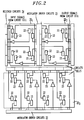
- FIG. 2 shows a schematic diagram of an integrated circuit constructed in accordance with the present invention.
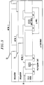
- FIG. 3 shows a schematic cross-sectional view of an integrated circuit having three levels of metalization.
- FIG. 4 shows a cross-sectional view of the bonded contacts used to connect the photodetectors and modulators to the electronic integrated circuit.
- FIG. 2 shows a top view of an integrated circuit having optical I/Os constructed in accordance with the present invention.
- the exemplary integrated circuit contains three fully-fabricated electronic circuit cells 20 1 , 20 2 and 20 3 that each perform predefined electrical processes on electrical signals received at their inputs.
- the integrated circuit may have any number of circuit cells 20 1 , 20 2 , ..., 20 n , or even a single circuit cell.
- the circuit cells 20 1 and 20 2 are illustratively shown with four input and four outputs while circuit cell 20 3 is shown with eight inputs and eight outputs. Of course, the actual number of inputs and outputs will depend on the requirements of each particular circuit cell.
- Each input of each circuit cell 20 1 , 20 2 and 20 3 receives an electrical input signal from an optical input comprising a photodetector 22 and a receiver circuit 24. Accordingly, circuit cells 20 1 and 20 2 are shown with four photodetector and receiver circuit pairs while circuit cell 20 3 is shown with eight photodetector and receiver circuit pairs. Likewise, each output of each circuit cell 20 1 , 20 2 and 20 3 provides an electrical output signal to an optical output comprising a modulator 23 and a modulator driver circuit 25. Accordingly, circuit cells 20 1 and 20 2 are shown with four modulator and modulator driver circuit pairs while circuit cell 20 3 is shown with eight modulator and modulator driver circuit pairs.
- the photodetectors 22 and modulators 23 may be formed from p-i-n diodes such as Multiple Quantum Well (MQW) p-i-n diodes.
- the photodetectors 22 alternatively may be formed from silicon metal semiconductor metal (MSM) devices.
- MSM silicon metal semiconductor metal
- the photodetectors 22 may be formed from silicon diodes or MSM devices and the modulators 23 and modulator driver circuits 25 may be formed from Vertical Cavity Surface Emitting Lasers (VCSELs) and VCSEL driver circuits respectively.
- VCSELs Vertical Cavity Surface Emitting Lasers
- the circuit cells constituting the entire electronic integrated circuit are first designed and optimized independently of and prior to the placement of the photodetectors and modulators on the integrated circuit. Optimization of the integrated circuit may involve the use of commercially available placement and routing tools that serve to minimize the area and maximize the clock frequency of the resulting integrated circuit. Accordingly, in contrast to conventional methods used to design smart pixels, the present invention places virtually no constraints on the integrated circuit design. As a result, the circuit cells constituting the integrated circuit may be highly complex and physically and functionally different from one another. Moreover, unlike the design of a smart pixel, the inventive method may be used with any of a wide variety of pre-existing high performance standard circuit cells, thus substantially reducing the amount of original electronic circuit design that must be performed. For example, standard cells may be selected from a commercially available library of circuit cells.
- the location of the photodetectors and the modulators on the integrated circuit may be selected.
- the photodetectors 22 and modulators 23 are typically arranged on the integrated circuit in a regular array.
- the photodetectors 22 and modulators 23 are illustratively shown as two interleaved grids. This regular pattern simplifies the optical system or systems required to transmit and receive the optical signals to and from the integrated circuit.
- the inventive method allows the location of the photodetectors and the modulators on each circuit cell to be selected without regard to the symmetry of the underlying circuit cells.
- a plurality of distinct circuit cells distributed over the integrated circuit in an asymmetric fashion may have optical I/Os that are collectively distributed in a symmetric arrangement which is dictated by the needs of the associated external optical system. This eliminates the need to completely redesign the integrated circuit for compatibility with optical I/Os.
- the inventive method allows an integrated circuit having a given symmetric arrangement to be provided with photodetectors and modulators that are distributed with a different symmetric arrangement. In this case the photodetectors and modulators may or may not have the same symmetry. If the symmetry of the photodetectors and modulators are different from one another, one of them may even have the same symmetry as the integrated circuit.
- the location of the receiver circuit 24 associated with each photodetector and the location of the modulator driver circuit 25 associated with each modulator also may be selected subsequent to designing the integrated circuit, based on considerations individual to each situation.
- the receiver circuits and the modulator driver circuits are shown distributed about the periphery of their respective circuit cells. Alternatively, these circuits may be situated at any other appropriately selected location on their respective circuit cells.
- the manner in which the photodetectors, modulators, receiver circuits and modulator driver circuits are all electrically connected to one another and to the circuit cells will be discussed with reference to FIG. 3.
- FIG. 3 shows a schematic cross-sectional view of a simplified integrated circuit.
- the exemplary integrated circuit includes a single inverter consisting of an n-MOS transistor and a p-MOS transistor.
- Electrical interconnections in conventional integrated circuits, particularly in VLSI circuits, are often formed from a multilevel metalization scheme to provide additional surface area on which interconnections can be made and to provide additional flexibility in circuit layout.
- three layers 30, 31 and 32 of metalization are employed which are separated from one another by insulator layers.
- Most commercial integrated circuit fabrication processes allow for the provision of at least three layers of metalization. However, most integrated circuits can be satisfactorily laid out and interconnected with only two layers of metalization.
- the topmost layer of metalization (which is commonly the third layer in many commercial silicon VLSI fabrication processes) can be reserved for bonding the photodetectors, modulators, receiver circuits and modulator driver circuits to the circuit cells and for interconnecting them to one another. That is, the topmost layer of metalization can be used to electrically couple the photodetectors to their respective receiver circuits and the receiver circuits to their respective electric inputs of the circuit cells. Similarly, the topmost layer of metalization also can be used to electrically couple the modulators to their respective modulator driver circuits and the modulator driver circuits to their respective electric outputs of the circuit cells.
- the topmost level can be used to bond and interconnect the I/O components and the remaining reserved levels of metalization can be used to form additional interconnections between the I/O components.
- the absolute placement of the arrays of optical inputs and outputs can be optimized to minimize interconnection lengths to the respective receiver circuits and modulator driver circuits. If necessary, an integrated circuit design that employs all available layers of metalization can be easily redesigned so that the topmost level is reserved for the optical I/Os.
- fabrication may proceed in accordance with a technique disclosed in U.S. Patent No. 5,385,632 for example, which is hereby incorporated by reference.
- this technique first requires that the integrated circuit be fully fabricated in a conventional manner.
- the optical I/Os are fully fabricated on a single substrate independently of the fabrication of the integrated circuit.
- the photodetectors and the modulators are arranged on the substrate in the array which was selected during the design process.
- the substrate containing the optical I/Os is then placed over the integrated circuit and properly aligned so that each photodetector and modulator is situated over its predetermined location on the integrated circuit selected during the design process.
- optical I/Os are then physically connected to the topmost level of metalization via bonded contacts as detailed in U.S. Patent No. 5,385,632.
- the bonding technique disclosed in this reference allows the photodetectors and modulators to be bonded anywhere on the individual circuit cells, including locations directly over active electronic circuitry.
- a fully-fabricated electronic integrated circuit was mounted onto a photoresist spinner chuck in order to apply a photoresist such as a 7 mm-thick film of Shipley 1075 photoresist, for example.
- the integrated circuit was mounted on a larger substrate of glass or silicon. Additional silicon material surrounded and contacted the integrated circuit to prevent a thick meniscus of photoresist from building up at its edges while spinning. This meniscus of photoresist could make subsequent alignment between the integrated circuit and the photomask extremely difficult.
- the photoresist was soft cured on a hot plate at 110 °C for 180 seconds after which the integrated circuit was removed from the larger substrate and placed in a mask aligner. The photoresist was exposed through a photomask having a pattern corresponding to the preselected sites of the bonded contacts. The integrated circuit was then developed to remove the photoresist from the preselected sites.
- a tri-level film of titanium, nickel, and gold was then evaporated onto the integrated circuit.
- the films can have a thickness ranging from about 25 - 500 ⁇ for titanium, 50 - 2000 ⁇ for nickel. and 500-2000 ⁇ for gold. While this particular choice of metals is well know to those of skill in the art, these thicknesses are much less than are conventionally employed. Thinner films may used in the present invention because the area over which the bonded contacts extend is much smaller than is typically employed.
- the integrated circuit is next immersed in a bath of acetone to dissolve the remaining photoresist, thereby removing the metal above it.
- solder such as lead-tin solder or pure indium solder, for example, may be deposited prior to immersion in the acetone.
- the solder is removed with the other metal layers when the photoresist is dissolved.
- FIG. 4 shows the resulting structure after this procedure has been completed.
- the optical I/Os were fully fabricated by a conventional method on a single substrate to form an optical integrated circuit. This circuit was then ready to be bonded onto the bonded contacts described above.
- the electrical and optical integrated circuits were mounted onto heated vacuum chucks and aligned by a commercially available flip-chip bonder.
- the integrated circuits were heated to 60 °C and brought into contact with one other with a force of 50-100 grams. The requisite force will in general depend on the total area of the bonded contacts.
- the force was maintained while the integrated circuits were heated to 140 - 200 °C. This temperature will in general depend on the ratio of lead to tin in the solder and may range up to 300 °C.
- a circuit cell was fabricated that consisted of an array of First-In First-Out (Fifo) memory buffers.
- the circuit cell was of a conventional design having sub-components selected from among a library of conventional designs.
- the array had 64 electrical inputs and 64 electrical outputs and each buffer had 32 bits of memory.
- 32 of the electrical inputs and outputs were provided with optical I/Os.
- the Fifo was implemented in a conventional 0.8 micron CMOS process.
- the interconnections for the electrical components within the Fifo circuit cell were all located within only two levels of metal. The third, topmost level of metal was used solely for connecting the optical I/Os to the circuit cell in the manner described above.
- the 32 receiver circuits were arranged in a linear array along the bottom periphery near the electrical inputs: Similarly, the 32 modulator driver circuits were arranged in a linear array along the top periphery near the electrical outputs.
- the photodetectors and modulators were arranged in regular arrays. Specifically, the photodetectors were arranged in a grid with four equally spaced columns of photodetectors and eight equally spaced rows of photodetectors.
- the modulators were arranged in a grid with sixteen equally spaced columns of modulators and two equally spaced rows of modulators.
- the photodetectors and modulators were fabricated from identical multiple quantum well (MQW) devices appropriately biased for each task.
- MQW multiple quantum well
- the optical performance of the Fifo data-buffer circuit was tested using one laser diode serving as an optical input source and another laser diode serving as an optical readout beam to be modulated by the modulators. Operation of the Fifo involved shifting bits through all 32 of its shift registers. Thirty-two bits of data were loaded into one electrical input of the Fifo by modulating the input laser diode. The data was then shifted through the corresponding Fifo buffer and transferred to the electrical output while the intensity modulation of the optical readout beam was monitored. These tests confirmed that satisfactory electrical and optical performance of the Fifo was achieved.
Abstract
Description
- The present invention relates generally to electronic integrated circuits and more particularly to electronic integrated circuits having optical inputs and outputs.
- The tremendous progress in high performance Very-Large Scale Integrated (VLSI) circuit technology now allows several million transistors to be incorporated onto a single silicon chip with on-chip clock rates as high as 200 MegaHertz (MHz). By the end of the decade, the integration density for silicon Complementary Metal Oxide Semiconductor (CMOS) technology is expected to be over 20 million transistors with a projected on-chip clock rate of 500 MHz. The enormous bandwidth that will be available for computation and switching on a silicon integrated circuit will create a huge bottleneck for the Inputs and Outputs (I/Os) that serve as interconnects to the VLSI circuit. Currently, the most widely used interconnect technique involves placing the I/Os along the periphery of the integrated circuit. A simple perimeter-versus-area calculation shows that the number of transistors per I/O channel will continue to increase, leading to an I/O performance bottleneck. In practice, off-chip clock rates are usually much smaller that on-chip clock rates, increasing the demands placed on the I/Os even further. Thus, a means of incorporating high-performance I/Os in a silicon chip is needed to fully exploit the tremendous computational capabilities of current and future VLSI circuits.
- Optical I/Os can overcome this bottleneck because of their greater bandwidth, immunity from crosstalk and signal interference. Additionally, optical I/Os can be fabricated in large, high density arrays. Optical I/Os have been used as interconnects for integrated circuits to form "smart pixels." An example of a smart pixel array is shown in FIG. 1. The array includes a plurality of individual
smart pixels 2 arranged in a symmetric manner. Each smart pixel includes anelectronic circuit cell 3, aphotodetector 4 with anassociated receiver circuit 5 and amodulator 6 with an associatedmodulator driver circuit 7. The circuit cell comprises related electronic circuitry that processes the electrical signal received at one or more of its inputs and produces an electrical signal at one or more of its outputs. The electronic circuit cell has a predefined number of electrical inputs and outputs. The particular nature of the circuit cell depends on the type of electrical processing it is to perform. Some common examples of a circuit cell include random-access memories, arithmetic logic units, and high-speed multipliers or even an entire VLSI chip. In the case of a conventional smart pixel array, the circuit cell is usually a simple logic circuit with about 100 transistors. Thephotodetector 4 and itsassociated receiver circuit 5 serve as the optical input that converts an optical input signal to an electrical input signal. Thephotodetector 4 first converts the optical input signal to a photocurrent. Thereceiver circuit 5 then converts the photocurrent to an appropriate voltage compatible for use as the electrical input to the circuit cell. Themodulator 6 and its associatedmodulator driver circuit 7 serve as the optical output that converts an electrical output signal from the circuit cell to an optical output signal. Themodulator driver circuit 7 receives the electrical output signal from thecircuit cell 3 and converts it to a voltage that is applied to themodulator 6. Themodulator 6 varies the intensity of an optical beam in proportion to the voltage applied to it. The optical beam thus modulated by themodulator 6 serves as the optical output signal. The photodetectors and modulators are typically reverse-biased diode devices. - The design of a smart pixel array proceeds as follows. First, the location of all the photodetectors and modulators on the entire integrated circuit is selected. The photodetectors and modulators are positioned so that they form a regular array. Such an arrangement is important because the optical input signals are usually generated by an external optical system that can most conveniently transmit the optical information to all the photodetectors as a series of parallel optical signals that are transmitted in a spatially symmetric manner. If the photodetectors were arranged in an irregular or asymmetric fashion, the complexity of the required optical system would be greatly increased. These same considerations apply to the modulators, which transmit the optical output signals to an external optical receiver that most conveniently receives the signals in a symmetric manner. After the location of the photodetectors and modulators have been determined, the layout of the entire electronic integrated circuit is performed. That is, the integrated circuit is partitioned into a series or array of circuit cells that in the case of smart pixels are referred to as pixels. Next, the particular location and size of each electronic component (e.g., transistor, capacitor and interconnection line) in a given pixel is determined. Since all the pixels in a smart pixel array are substantially identical, once the design of a single pixel have been completed, it may be replicated for the remaining pixels.
- As detailed above, the electronic integrated circuit in a smart pixel array is not designed independently of the optical I/Os. That is, the smart pixel design process preselects the location of the photodetectors and modulators prior to designing the electronic integrated circuit. This places severe constraints on the design of the electronic integrated circuit, limiting the designer's flexibility in sizing and locating the transistors and interconnection lines. Thus, for example, the maximum level of complexity of each circuit cell (i.e., pixel) is typically dictated by the available area between the predetermined location of the photodetectors and modulators. Due to these constraints placed on the design of a smart pixel array, the circuit cells in the array are typically limited to low levels of complexity, are homogeneous relative to one another, and have limited electrical communication with one another.
- Optical I/Os for integrated circuits other than those used in smart pixel arrays is problematic. In general, an integrated circuit contains numerous circuit cells that are highly complex and non-homogeneous in terms of both their function and in terms of the number of electronic components such as transistors and interconnects that they employ. As a result, the constraints imposed on electronic integrated circuits which are designed by the previously-described design procedure prevent such complex integrated circuits from being supplied with optical I/Os.
- The inventive method allows optical I/Os to be used in integrated circuits that contain a wide variety of different and highly-complex circuit cells, even when those circuit cells are arranged in a spatially asymmetric manner. Moreover, there is no need to substantially redesign conventional electronic circuits so as to be compatible with the optical I/Os. In contrast to the methods used to design smart pixels, the inventors have realized that by reserving a topmost layer of metalization for electrically interconnecting the optical I/Os, the electronic integrated circuit may be designed without taking into account the location of the optical I/Os on the integrated circuit. Accordingly, the designer has as much flexibility available in designing an electronic integrated circuit with optical I/Os as is available when no optical I/Os are provided.
- In accordance with the inventive method, an electronic integrated circuit design is selected which includes at least one circuit cell design for processing electric signals. The circuit cell design has a predetermined number of electric inputs and electric outputs. The integrated circuit design also includes a plurality of layers of metalization for providing electric coupling. After the electronic integrated circuit design is selected, a predetermined number of optical input devices are located on the circuit cell design in a first prearranged orientation. The predetermined number of optical input devices is no greater than the predetermined number of electric inputs to the circuit cell. Also after the electronic circuit design is selected, a predetermined number of optical output devices are located on the circuit cell design in a second prearranged orientation. The predetermined number of optical output devices is no greater than the predetermined number of electric outputs to the circuit cell. At least a topmost layer of metalization is selected for electrically coupling each optical input device to a distinct one of the electric inputs of the circuit cell and for electrically coupling each optical output device to a distinct one of the electric outputs of the circuit cell. Finally, the completed design for the integrated circuit with optical inputs and outputs is recorded in a memory such as an electronic storage medium. The device may then be fabricated in accordance with the recorded design.
- FIG. 1 shows a conventional smart pixel array.
- FIG. 2 shows a schematic diagram of an integrated circuit constructed in accordance with the present invention.
- FIG. 3 shows a schematic cross-sectional view of an integrated circuit having three levels of metalization.
- FIG. 4 shows a cross-sectional view of the bonded contacts used to connect the photodetectors and modulators to the electronic integrated circuit.
- FIG. 2 shows a top view of an integrated circuit having optical I/Os constructed in accordance with the present invention. The exemplary integrated circuit contains three fully-fabricated electronic circuit cells 201, 202 and 203 that each perform predefined electrical processes on electrical signals received at their inputs. In general, the integrated circuit may have any number of circuit cells 201, 202, ..., 20n, or even a single circuit cell. In FIG. 2, the circuit cells 201 and 202 are illustratively shown with four input and four outputs while circuit cell 203 is shown with eight inputs and eight outputs. Of course, the actual number of inputs and outputs will depend on the requirements of each particular circuit cell.
- Each input of each circuit cell 201, 202 and 203 receives an electrical input signal from an optical input comprising a
photodetector 22 and areceiver circuit 24. Accordingly, circuit cells 201 and 202 are shown with four photodetector and receiver circuit pairs while circuit cell 203 is shown with eight photodetector and receiver circuit pairs. Likewise, each output of each circuit cell 201, 202 and 203 provides an electrical output signal to an optical output comprising amodulator 23 and amodulator driver circuit 25. Accordingly, circuit cells 201 and 202 are shown with four modulator and modulator driver circuit pairs while circuit cell 203 is shown with eight modulator and modulator driver circuit pairs. In one embodiment of the invention, thephotodetectors 22 andmodulators 23 may be formed from p-i-n diodes such as Multiple Quantum Well (MQW) p-i-n diodes. Thephotodetectors 22 alternatively may be formed from silicon metal semiconductor metal (MSM) devices. Various combinations are also possible. For example. thephotodetectors 22 may be formed from silicon diodes or MSM devices and themodulators 23 andmodulator driver circuits 25 may be formed from Vertical Cavity Surface Emitting Lasers (VCSELs) and VCSEL driver circuits respectively. It should be noted that while the above description refers to the optical inputs and outputs as including the receiver circuit and the modulator driver circuit, respectively, these components may be alternatively associated with their respective electrical inputs and outputs. In this case the optical input refers only to the photodetector and the optical output refers only to the modulator. - In accordance with the present invention, the circuit cells constituting the entire electronic integrated circuit are first designed and optimized independently of and prior to the placement of the photodetectors and modulators on the integrated circuit. Optimization of the integrated circuit may involve the use of commercially available placement and routing tools that serve to minimize the area and maximize the clock frequency of the resulting integrated circuit. Accordingly, in contrast to conventional methods used to design smart pixels, the present invention places virtually no constraints on the integrated circuit design. As a result, the circuit cells constituting the integrated circuit may be highly complex and physically and functionally different from one another. Moreover, unlike the design of a smart pixel, the inventive method may be used with any of a wide variety of pre-existing high performance standard circuit cells, thus substantially reducing the amount of original electronic circuit design that must be performed. For example, standard cells may be selected from a commercially available library of circuit cells.
- After the integrated circuit has been designed the location of the photodetectors and the modulators on the integrated circuit may be selected. As illustratively shown in FIG. 2, the
photodetectors 22 andmodulators 23 are typically arranged on the integrated circuit in a regular array. In particular, thephotodetectors 22 andmodulators 23 are illustratively shown as two interleaved grids. This regular pattern simplifies the optical system or systems required to transmit and receive the optical signals to and from the integrated circuit. In contrast to prior integrated circuits having optical I/Os such as the smart pixels discussed above, the inventive method allows the location of the photodetectors and the modulators on each circuit cell to be selected without regard to the symmetry of the underlying circuit cells. That is, a plurality of distinct circuit cells distributed over the integrated circuit in an asymmetric fashion may have optical I/Os that are collectively distributed in a symmetric arrangement which is dictated by the needs of the associated external optical system. This eliminates the need to completely redesign the integrated circuit for compatibility with optical I/Os. Moreover, the inventive method allows an integrated circuit having a given symmetric arrangement to be provided with photodetectors and modulators that are distributed with a different symmetric arrangement. In this case the photodetectors and modulators may or may not have the same symmetry. If the symmetry of the photodetectors and modulators are different from one another, one of them may even have the same symmetry as the integrated circuit. - The location of the
receiver circuit 24 associated with each photodetector and the location of themodulator driver circuit 25 associated with each modulator also may be selected subsequent to designing the integrated circuit, based on considerations individual to each situation. In FIG. 2 for example. the receiver circuits and the modulator driver circuits are shown distributed about the periphery of their respective circuit cells. Alternatively, these circuits may be situated at any other appropriately selected location on their respective circuit cells. The manner in which the photodetectors, modulators, receiver circuits and modulator driver circuits are all electrically connected to one another and to the circuit cells will be discussed with reference to FIG. 3. - FIG. 3 shows a schematic cross-sectional view of a simplified integrated circuit. The exemplary integrated circuit includes a single inverter consisting of an n-MOS transistor and a p-MOS transistor. Electrical interconnections in conventional integrated circuits, particularly in VLSI circuits, are often formed from a multilevel metalization scheme to provide additional surface area on which interconnections can be made and to provide additional flexibility in circuit layout. In the illustrative integrated circuit shown in FIG. 3 three
layers - After the integrated circuit with its optical I/Os has been designed, fabrication may proceed in accordance with a technique disclosed in U.S. Patent No. 5,385,632 for example, which is hereby incorporated by reference. In summary, this technique first requires that the integrated circuit be fully fabricated in a conventional manner. Similarly, the optical I/Os are fully fabricated on a single substrate independently of the fabrication of the integrated circuit. The photodetectors and the modulators are arranged on the substrate in the array which was selected during the design process. The substrate containing the optical I/Os is then placed over the integrated circuit and properly aligned so that each photodetector and modulator is situated over its predetermined location on the integrated circuit selected during the design process. The optical I/Os are then physically connected to the topmost level of metalization via bonded contacts as detailed in U.S. Patent No. 5,385,632. The bonding technique disclosed in this reference allows the photodetectors and modulators to be bonded anywhere on the individual circuit cells, including locations directly over active electronic circuitry.
- The following discussion provides some additional details of the fabrication technique disclosed in the previously-referenced patent that has been used in connection with the inventive method. A fully-fabricated electronic integrated circuit was mounted onto a photoresist spinner chuck in order to apply a photoresist such as a 7 mm-thick film of Shipley 1075 photoresist, for example. The integrated circuit was mounted on a larger substrate of glass or silicon. Additional silicon material surrounded and contacted the integrated circuit to prevent a thick meniscus of photoresist from building up at its edges while spinning. This meniscus of photoresist could make subsequent alignment between the integrated circuit and the photomask extremely difficult.
- The photoresist was soft cured on a hot plate at 110 °C for 180 seconds after which the integrated circuit was removed from the larger substrate and placed in a mask aligner. The photoresist was exposed through a photomask having a pattern corresponding to the preselected sites of the bonded contacts. The integrated circuit was then developed to remove the photoresist from the preselected sites.
- A tri-level film of titanium, nickel, and gold was then evaporated onto the integrated circuit. The films can have a thickness ranging from about 25 - 500 Å for titanium, 50 - 2000 Å for nickel. and 500-2000 Å for gold. While this particular choice of metals is well know to those of skill in the art, these thicknesses are much less than are conventionally employed. Thinner films may used in the present invention because the area over which the bonded contacts extend is much smaller than is typically employed. The integrated circuit is next immersed in a bath of acetone to dissolve the remaining photoresist, thereby removing the metal above it. Optionally, a 34 mm-thick film of solder such as lead-tin solder or pure indium solder, for example, may be deposited prior to immersion in the acetone. The solder is removed with the other metal layers when the photoresist is dissolved. FIG. 4 shows the resulting structure after this procedure has been completed.
- Independently of the procedure delineated above, the optical I/Os were fully fabricated by a conventional method on a single substrate to form an optical integrated circuit. This circuit was then ready to be bonded onto the bonded contacts described above. First, the electrical and optical integrated circuits were mounted onto heated vacuum chucks and aligned by a commercially available flip-chip bonder. The integrated circuits were heated to 60 °C and brought into contact with one other with a force of 50-100 grams. The requisite force will in general depend on the total area of the bonded contacts. The force was maintained while the integrated circuits were heated to 140 - 200 °C. This temperature will in general depend on the ratio of lead to tin in the solder and may range up to 300 °C. Once the desired temperature was reached, the force was maintained for 60-120 seconds, after which the optical integrated circuit was released from its vacuum chuck. The completed structure was cooled to 60 °C and removed from the bonder. Additional details concerning the fabrication process such as the removal of the substrate from the optical integrated circuit can be found in U.S. Patent No. 5,385,632.
- In one example of the invention, a circuit cell was fabricated that consisted of an array of First-In First-Out (Fifo) memory buffers. The circuit cell was of a conventional design having sub-components selected from among a library of conventional designs. The array had 64 electrical inputs and 64 electrical outputs and each buffer had 32 bits of memory. In accordance with the inventive method, 32 of the electrical inputs and outputs were provided with optical I/Os. The Fifo was implemented in a conventional 0.8 micron CMOS process. The interconnections for the electrical components within the Fifo circuit cell were all located within only two levels of metal. The third, topmost level of metal was used solely for connecting the optical I/Os to the circuit cell in the manner described above. The 32 receiver circuits were arranged in a linear array along the bottom periphery near the electrical inputs: Similarly, the 32 modulator driver circuits were arranged in a linear array along the top periphery near the electrical outputs. The photodetectors and modulators were arranged in regular arrays. Specifically, the photodetectors were arranged in a grid with four equally spaced columns of photodetectors and eight equally spaced rows of photodetectors. The modulators were arranged in a grid with sixteen equally spaced columns of modulators and two equally spaced rows of modulators. The photodetectors and modulators were fabricated from identical multiple quantum well (MQW) devices appropriately biased for each task.
- The optical performance of the Fifo data-buffer circuit was tested using one laser diode serving as an optical input source and another laser diode serving as an optical readout beam to be modulated by the modulators. Operation of the Fifo involved shifting bits through all 32 of its shift registers. Thirty-two bits of data were loaded into one electrical input of the Fifo by modulating the input laser diode. The data was then shifted through the corresponding Fifo buffer and transferred to the electrical output while the intensity modulation of the optical readout beam was monitored. These tests confirmed that satisfactory electrical and optical performance of the Fifo was achieved.
Claims (27)
- A method comprising(a) selecting an electronic integrated circuit design having at least one circuit cell design for processing electric signals, said circuit cell design having a predetermined number of electric inputs and electric outputs, said integrated circuit design further including a plurality of layers of metalization for providing electric coupling;(b) subsequent to step (a), locating a predetermined number of optical input devices on the circuit cell design in a first prearranged orientation;(c) subsequent to step (a), locating a predetermined number of optical output devices on the circuit cell design in a second prearranged orientation;(d) selecting at least a topmost layer of metalization for electrically coupling each optical input device to a respective one of said electric inputs of the circuit cell and for electrically coupling each optical output device to a respective one of said electric outputs of the circuit cell;(e) fabricating an integrated circuit with optical inputs and outputs in accordance with steps (a)-(d).
- A method comprising the steps of:(a) selecting an electronic integrated circuit design having a plurality of circuit cell designs for processing electric signals, said circuit cell designs being different from one another such that the electronic integrated circuit is asymmetrically distributed over its surface, said integrated circuit having a predetermined number of electric inputs and electric outputs and including a plurality of layers of metalization for providing electric coupling;(b) locating a predetermined number of optical input devices on the plurality of circuit cell designs in a first symmetric arrangement, the predetermined number of optical input devices being no greater than the predetermined number of electric inputs to the electronic integrated circuit;(c) locating a predetermined number of optical output devices on the plurality of circuit cell designs in a second symmetric orientation, the predetermined number of optical output devices being no greater than the predetermined number of electric outputs to the electronic integrated circuit;(d) selecting at least a topmost layer of metalization for electrically coupling each optical input device to a distinct one of said electric inputs of the electronic integrated circuit and for electrically coupling each optical output device to a distinct one of said electric outputs of the electronic integrated circuit;(e) fabricating an integrated circuit with optical inputs and outputs in accordance with steps (a)-(d).
- A method of constructing an apparatus, said method comprising the steps of:(a) selecting an electronic integrated circuit design having at least one circuit cell design for processing electric signals, said circuit cell design having a predetermined number of electric inputs and electric outputs, said integrated circuit design further including a plurality of layers of metalization for providing electric coupling;(b) subsequent to step (a), locating a predetermined number of optical input devices on the circuit cell design in a first prearranged orientation, the predetermined number of optical input devices being no greater than the predetermined number of electric inputs to the circuit cell;(c) subsequent to step (a), locating a predetermined number of optical output devices on the circuit cell design in a second prearranged orientation, the predetermined number of optical output devices being no greater than the predetermined number of electric outputs to the circuit cell;(d) selecting at least a topmost layer of metalization for electrically coupling each optical input device to a distinct one of said electric inputs of the circuit cell and for electrically coupling each optical output device to a distinct one of said electric outputs of the circuit cell.
- An apparatus comprising:(a) an integrated circuit having a plurality of circuit cells for processing electric signals, said circuit cells being different from one another such that the electronic integrated circuit is asymmetrically distributed over its surface, said integrated circuit having a predetermined number of electric inputs and electric outputs and including a plurality of layers of metalization for providing electric coupling;(b) a predetermined number of optical input devices electrically coupled to a distinct one of said electric inputs of the integrated circuit, said predetermined number of optical input devices being distributed in a first symmetric arrangement on the electronic integrated circuit;(c) a predetermined number of optical output devices electrically coupled to a distinct one of said electric outputs of the integrated circuit, said predetermined number of optical input devices being distributed in a second symmetric arrangement on the electronic integrated circuit;(d) wherein a topmost layer of metalization electrically couples the optical input devices to the electric inputs and the optical output devices to electric outputs.
- An apparatus comprising:(a) an integrated circuit having a plurality of circuit cells for processing electric signals, said circuit cells being arranged such that the electronic integrated circuit has a first symmetric arrangement over its surface. said integrated circuit having a predetermined number of electric inputs and electric outputs and including a plurality of layers of metalization for providing electric coupling;(b) a predetermined number of optical input devices electrically coupled to a distinct one of said electric inputs of the integrated circuit, said predetermined number of optical input devices being distributed in a second symmetric arrangement on the electronic integrated circuit, said first symmetric arrangement being different from said second symmetric arrangement;(c) a predetermined number of optical output devices electrically coupled to a distinct one of said electric outputs of the integrated circuit, said predetermined number of optical input devices being distributed in a third symmetric arrangement on the electronic integrated circuit;(d) wherein a topmost layer of metalization electrically couples the optical input devices to the electric inputs and the optical output devices to electric outputs.
- An apparatus comprising:(a) an integrated circuit having a plurality of circuit cells for processing electric signals, said circuit cells being arranged such that the electronic integrated circuit has a first symmetric arrangement over its surface, said integrated circuit having a predetermined number of electric inputs and electric outputs and including a plurality of layers of metalization for providing electric coupling;(b) a predetermined number of optical input devices electrically coupled to a distinct one of said electric inputs of the integrated circuit, said predetermined number of optical input devices being distributed in a second symmetric arrangement on the electronic integrated circuit;(c) a predetermined number of optical output devices electrically coupled to a distinct one of said electric outputs of the integrated circuit, said predetermined number of optical input devices being distributed in a third symmetric arrangement on the electronic integrated circuit, said first symmetric arrangement being different from said third symmetric arrangement;(d) wherein a topmost layer of metalization electrically couples the optical input devices to the electric inputs and the optical output devices to electric outputs.
- A method comprising the steps of:(a) selecting an electronic integrated circuit design having at least one circuit cell design for processing electric signals, said circuit cell design having a predetermined number of electric inputs and electric outputs, said integrated circuit design further including a plurality of layers of metalization for providing electric coupling;(b) subsequent to step (a), locating a predetermined number of optical input devices on the circuit cell design in a first prearranged orientation, the predetermined number of optical input devices being no greater than the predetermined number of electric inputs to the circuit cell;(c) subsequent to step (a), locating a predetermined number of optical output devices on the circuit cell design in a second prearranged orientation, the predetermined number of optical output devices being no greater than the predetermined number of electric outputs to the circuit cell;(d) selecting at least a topmost layer of metalization for electrically coupling each optical input device to a distinct one of said electric inputs of the circuit cell and for electrically coupling each optical output device to a distinct one of said electric outputs of the circuit cell;(e) recording in a memory a design for an integrated circuit with optical inputs and outputs in accordance with steps (a)-(d).
- The method of claim 1 or the apparatus of claim 4,5 or 6 wherein the optical input devices each comprise a photodetector for converting an optical input signal to a photocurrent and a receiver circuit coupled to said photodetector for converting said photocurrent to an electric input signal.
- The method of claim 2 or the apparatus of claim 4,5,6, or 8, wherein the optical output devices each comprise a modulator driver circuit for converting an electric output signal to a voltage signal and a modulator coupled to said modulator driver circuit for converting said voltage signal to an optical output signal.
- The method of claim 1,2,3 or 7, or the apparatus of claim 4,5, or 6, wherein said first and second prearranged orientations form regular arrays.
- The method of claim 1 wherein said electronic integrated circuit design includes a plurality of circuit cell designs, and further comprising the steps of repeating steps (b)-(d) for each of the circuit cells designs.
- The method of claim 11, wherein said plurality of circuit cell designs form a spatially asymmetric electronic integrated circuit designs and wherein said first prearranged orientations for the circuit cell designs form a first common symmetric arrangement and said second prearranged orientations for the circuit cells form a second common symmetric arrangement.
- The method of claim 1,2,3 or 7, or the apparatus of claim 4,5 or 6, wherein said plurality of layers of metalization comprise three layers of metalization.
- The method of claim 1 wherein said selecting step comprises the step of selecting a standard electronic integrated circuit design from among a library of electronic integrated circuit designs.
- The method of claim 1,2,3 or 7, or the apparatus of claim 4,5 or 6 wherein each of said electric inputs includes a receiver circuit for converting a photocurrent to an electric input signal and each of said electric outputs includes a modulator driver circuit for converting an electric output signal to a voltage signal.
- The method of claim 1,2,3 or 7 or 15, or the apparatus of claim 4,5 or 6 wherein said optical input devices each comprise a photodetector and said optical output devices each comprise a modulator.
- The method of claim I wherein the step of selecting an electronic integrated circuit design comprises the step of optimizing the integrated circuit design independent of performing steps (b) and (c).
- The method of claim 17, wherein the optimization step comprises the step of optimizing at least one characteristic selected from the group consisting of the area of the integrated circuit, the clock frequency of the circuit cell, and the power dissipation of the circuit cell.
- The method or apparatus of claim 15, wherein said receiver circuits and said modulator driver circuits are located along a periphery of the circuit cell.
- The method of claim 16, wherein the fabricating step comprises the steps of:fully fabricating the electronic integrated circuit;fully fabricating the predetermined number of optical input devices and optical output devices on a common substrate to form a fully fabricated optical integrated circuit;aligning said fully fabricated optical integrated circuit over said fully fabricated electronic integrated circuit so that each of the optical input devices and optical output devices are situated over a predetermined location on the electronic integrated circuit;bonding said fully fabricated electronic integrated circuit to said fully fabricated optical integrated circuit.
- The method of claim 20 or the apparatus of claim 4,5 or 6, wherein
at least one optical input and/or output device is bonded to a location on the fully fabricated electronic integrated circuit situated over active electronic circuitry. - The method of claim 1,2,3, or 7, wherein said circuit cell design is a pixel design, and/or
is a First-In First-Out memory buffer design. - The method or apparatus of claim 16 wherein said photodetectors and said modulators are multiple quantum well p-i-n diodes.
- The method or apparatus of claim 16 wherein said photodetectors are multiple quantum well p-i-n diodes and said modulators are vertical cavity surface emitting lasers.
- The method or apparatus of claim 16, wherein said photodetectors are silicon diodes and said modulators are multiple quantum well p-i-n diodes.
- The method or apparatus of claim 16, wherein said photodetectors are metal-semiconductor-metal devices and said modulators are vertical cavity surface emitting lasers.
- The method or apparatus of claim 16, wherein said photodetectors are metal-semiconductor-metal devices and said modulators are multiple quantum well p-i-n diodes.
Applications Claiming Priority (2)
| Application Number | Priority Date | Filing Date | Title |
|---|---|---|---|
| US08/403,316 US5605856A (en) | 1995-03-14 | 1995-03-14 | Method for designing an electronic integrated circuit with optical inputs and outputs |
| US403316 | 1995-03-14 |
Publications (2)
| Publication Number | Publication Date |
|---|---|
| EP0734068A2 true EP0734068A2 (en) | 1996-09-25 |
| EP0734068A3 EP0734068A3 (en) | 1997-10-29 |
Family
ID=23595345
Family Applications (1)
| Application Number | Title | Priority Date | Filing Date |
|---|---|---|---|
| EP96301482A Withdrawn EP0734068A3 (en) | 1995-03-14 | 1996-03-05 | Method for designing an electronic integrated circuit with optical inputs and outputs |
Country Status (4)
| Country | Link |
|---|---|
| US (2) | US5605856A (en) |
| EP (1) | EP0734068A3 (en) |
| JP (1) | JPH0936344A (en) |
| CA (1) | CA2170431A1 (en) |
Cited By (2)
| Publication number | Priority date | Publication date | Assignee | Title |
|---|---|---|---|---|
| GB2340998A (en) * | 1998-08-26 | 2000-03-01 | Lsi Logic Corp | Optical/electrical inputs for integrated circuits |
| WO2001018567A2 (en) * | 1999-09-03 | 2001-03-15 | Teraconnect, Inc | Optoelectronic connector system |
Families Citing this family (41)
| Publication number | Priority date | Publication date | Assignee | Title |
|---|---|---|---|---|
| US5914889A (en) * | 1996-09-13 | 1999-06-22 | Lucent Technologies Inc. | Method and system for generating a mask layout of an optical integrated circuit |
| US6393169B1 (en) | 1997-12-19 | 2002-05-21 | Intel Corporation | Method and apparatus for providing optical interconnection |
| US6374003B1 (en) | 1997-12-19 | 2002-04-16 | Intel Corporation | Method and apparatus for optically modulating light through the back side of an integrated circuit die using a plurality of optical beams |
| US6330376B1 (en) | 1997-12-19 | 2001-12-11 | Intel Corporation | Higher order rejection method and apparatus for optical modulator |
| US6049639A (en) * | 1997-12-19 | 2000-04-11 | Intel Corporation | Method and apparatus providing optical input/output through the back side of an integrated circuit die |
| US6052498A (en) * | 1997-12-19 | 2000-04-18 | Intel Corporation | Method and apparatus providing an optical input/output bus through the back side of an integrated circuit die |
| US6075908A (en) * | 1997-12-19 | 2000-06-13 | Intel Corporation | Method and apparatus for optically modulating light through the back side of an integrated circuit die |
| US5977571A (en) * | 1998-02-26 | 1999-11-02 | Lucent Technologies, Inc. | Low loss connecting arrangement for photodiodes |
| US6262450B1 (en) | 1998-04-22 | 2001-07-17 | International Business Machines Corporation | DRAM stack capacitor with vias and conductive connection extending from above conductive lines to the substrate |
| US6466349B1 (en) * | 1998-05-14 | 2002-10-15 | Hughes Electronics Corporation | Integrated optical transmitter |
| US6097748A (en) * | 1998-05-18 | 2000-08-01 | Motorola, Inc. | Vertical cavity surface emitting laser semiconductor chip with integrated drivers and photodetectors and method of fabrication |
| US6587605B2 (en) | 1999-01-06 | 2003-07-01 | Intel Corporation | Method and apparatus for providing optical interconnection |
| DE19907168C1 (en) * | 1999-02-19 | 2000-08-10 | Micronas Intermetall Gmbh | Layer arrangement and method for its production |
| US6586812B1 (en) * | 1999-04-13 | 2003-07-01 | Agilent Technologies, Inc. | Isolation of alpha silicon diode sensors through ion implantation |
| US6249044B1 (en) * | 1999-06-17 | 2001-06-19 | National Semiconductor Corp. | Opaque metallization to cover flip chip die surface for light sensitive semiconductor devices |
| US6215577B1 (en) | 1999-10-25 | 2001-04-10 | Intel Corporation | Method and apparatus for optically modulating an optical beam with a multi-pass wave-guided optical modulator |
| US6501092B1 (en) | 1999-10-25 | 2002-12-31 | Intel Corporation | Integrated semiconductor superlattice optical modulator |
| US6268953B1 (en) | 1999-12-02 | 2001-07-31 | Intel Corporation | Method and apparatus for optically modulating an optical beam with long interaction length optical modulator |
| US6351326B1 (en) | 1999-12-14 | 2002-02-26 | Intel Corporation | Method and apparatus for optically modulating light utilizing a resonant cavity structure |
| US6504977B1 (en) | 2000-02-01 | 2003-01-07 | Agere Systems, Inc. | Integrated CMOS pigtailed receiver using CMOS-compatible optical bench |
| US6532580B1 (en) * | 2000-02-18 | 2003-03-11 | Hewlett-Packard Company | In-place method for inserting repeater buffers in an integrated circuit |
| US6583445B1 (en) | 2000-06-16 | 2003-06-24 | Peregrine Semiconductor Corporation | Integrated electronic-optoelectronic devices and method of making the same |
| WO2002075785A2 (en) | 2001-03-16 | 2002-09-26 | Peregrine Semiconductor Corporation | Coupled optical and optoelectronic devices, and method of making the same |
| US6947615B2 (en) | 2001-05-17 | 2005-09-20 | Sioptical, Inc. | Optical lens apparatus and associated method |
| US6912330B2 (en) | 2001-05-17 | 2005-06-28 | Sioptical Inc. | Integrated optical/electronic circuits and associated methods of simultaneous generation thereof |
| US6654511B2 (en) | 2001-05-17 | 2003-11-25 | Sioptical, Inc. | Optical modulator apparatus and associated method |
| US6891685B2 (en) * | 2001-05-17 | 2005-05-10 | Sioptical, Inc. | Anisotropic etching of optical components |
| US6493502B1 (en) | 2001-05-17 | 2002-12-10 | Optronx, Inc. | Dynamic gain equalizer method and associated apparatus |
| US6748125B2 (en) | 2001-05-17 | 2004-06-08 | Sioptical, Inc. | Electronic semiconductor control of light in optical waveguide |
| US6603889B2 (en) | 2001-05-17 | 2003-08-05 | Optronx, Inc. | Optical deflector apparatus and associated method |
| US6646747B2 (en) | 2001-05-17 | 2003-11-11 | Sioptical, Inc. | Interferometer apparatus and associated method |
| US6625348B2 (en) | 2001-05-17 | 2003-09-23 | Optron X, Inc. | Programmable delay generator apparatus and associated method |
| US6608945B2 (en) | 2001-05-17 | 2003-08-19 | Optronx, Inc. | Self-aligning modulator method and associated apparatus |
| US6690844B2 (en) | 2001-05-17 | 2004-02-10 | Optronx, Inc. | Optical fiber apparatus and associated method |
| US6526187B1 (en) | 2001-05-17 | 2003-02-25 | Optronx, Inc. | Polarization control apparatus and associated method |
| JP2006201500A (en) * | 2005-01-20 | 2006-08-03 | Sony Corp | Semiconductor integrated circuit and electronic equipment using the same |
| US7700975B2 (en) * | 2006-03-31 | 2010-04-20 | Intel Corporation | Schottky barrier metal-germanium contact in metal-germanium-metal photodetectors |
| US20070235877A1 (en) * | 2006-03-31 | 2007-10-11 | Miriam Reshotko | Integration scheme for semiconductor photodetectors on an integrated circuit chip |
| US20080001181A1 (en) * | 2006-06-28 | 2008-01-03 | Titash Rakshit | Complementarily doped metal-semiconductor interfaces to reduce dark current in MSM photodetectors |
| TWI615647B (en) | 2014-10-27 | 2018-02-21 | 藝蘭能工藝有限責任公司 | Photonic interface for electronic circuit |
| US11573834B2 (en) * | 2019-08-22 | 2023-02-07 | Micron Technology, Inc. | Computational partition for a multi-threaded, self-scheduling reconfigurable computing fabric |
Citations (5)
| Publication number | Priority date | Publication date | Assignee | Title |
|---|---|---|---|---|
| EP0405815A1 (en) * | 1989-06-23 | 1991-01-02 | Nortel Networks Corporation | Spatial light modulators |
| EP0469216A1 (en) * | 1990-07-31 | 1992-02-05 | International Business Machines Corporation | Method of forming metal contact pads and terminals on semiconductor chips |
| US5198684A (en) * | 1990-08-15 | 1993-03-30 | Kabushiki Kaisha Toshiba | Semiconductor integrated circuit device with optical transmit-receive means |
| US5280184A (en) * | 1992-04-08 | 1994-01-18 | Georgia Tech Research Corporation | Three dimensional integrated circuits with lift-off |
| US5385632A (en) * | 1993-06-25 | 1995-01-31 | At&T Laboratories | Method for manufacturing integrated semiconductor devices |
Family Cites Families (16)
| Publication number | Priority date | Publication date | Assignee | Title |
|---|---|---|---|---|
| JPS6033342B2 (en) * | 1979-06-04 | 1985-08-02 | 株式会社日立製作所 | solid state imaging device |
| US4734380A (en) * | 1983-04-08 | 1988-03-29 | American Telephone And Telegraph Company, At&T Bell Laboratories | Multicavity optical device held together by metallic film |
| US5426312A (en) * | 1989-02-23 | 1995-06-20 | British Telecommunications Public Limited Company | Fabry-perot modulator |
| DE69013190T2 (en) * | 1989-03-14 | 1995-02-16 | Fujitsu Ltd | Semiconductor device with pin photodiode. |
| US4984861A (en) * | 1989-03-27 | 1991-01-15 | United Technologies Corporation | Low-loss proton exchanged waveguides for active integrated optic devices and method of making same |
| US5339090A (en) * | 1989-06-23 | 1994-08-16 | Northern Telecom Limited | Spatial light modulators |
| JPH0642527B2 (en) * | 1989-10-10 | 1994-06-01 | 日本電気株式会社 | Information processing device using optical waveguide |
| JP2811131B2 (en) * | 1991-04-26 | 1998-10-15 | 三菱電機株式会社 | Wiring connection structure of semiconductor device and method of manufacturing the same |
| US5328853A (en) * | 1993-06-18 | 1994-07-12 | The United States Of America As Represented By The Secretary Of The Navy | Method of making a photodetector array having high pixel density |
| US5375180A (en) * | 1993-10-04 | 1994-12-20 | At&T Corp. | Process tolerant reverse delta-beta directional coupler switch and method of fabricating same |
| US5389776A (en) * | 1993-11-22 | 1995-02-14 | At&T Corp. | FET-based optical receiver |
| US5606572A (en) * | 1994-03-24 | 1997-02-25 | Vixel Corporation | Integration of laser with photodiode for feedback control |
| US5625729A (en) * | 1994-08-12 | 1997-04-29 | Brown; Thomas G. | Optoelectronic device for coupling between an external optical wave and a local optical wave for optical modulators and detectors |
| MX9704632A (en) * | 1994-12-23 | 1998-02-28 | Digirad | Semiconductor gamma-ray camera and medical imaging system. |
| JP3165779B2 (en) * | 1995-07-18 | 2001-05-14 | 株式会社トクヤマ | Submount |
| US5929474A (en) * | 1997-03-10 | 1999-07-27 | Motorola, Inc. | Active matrix OED array |
-
1995
- 1995-03-14 US US08/403,316 patent/US5605856A/en not_active Expired - Lifetime
-
1996
- 1996-02-27 CA CA002170431A patent/CA2170431A1/en not_active Abandoned
- 1996-03-05 EP EP96301482A patent/EP0734068A3/en not_active Withdrawn
- 1996-03-13 JP JP5568496A patent/JPH0936344A/en active Pending
- 1996-08-12 US US08/695,496 patent/US6034431A/en not_active Expired - Lifetime
Patent Citations (5)
| Publication number | Priority date | Publication date | Assignee | Title |
|---|---|---|---|---|
| EP0405815A1 (en) * | 1989-06-23 | 1991-01-02 | Nortel Networks Corporation | Spatial light modulators |
| EP0469216A1 (en) * | 1990-07-31 | 1992-02-05 | International Business Machines Corporation | Method of forming metal contact pads and terminals on semiconductor chips |
| US5198684A (en) * | 1990-08-15 | 1993-03-30 | Kabushiki Kaisha Toshiba | Semiconductor integrated circuit device with optical transmit-receive means |
| US5280184A (en) * | 1992-04-08 | 1994-01-18 | Georgia Tech Research Corporation | Three dimensional integrated circuits with lift-off |
| US5385632A (en) * | 1993-06-25 | 1995-01-31 | At&T Laboratories | Method for manufacturing integrated semiconductor devices |
Non-Patent Citations (4)
| Title |
|---|
| APPLIED OPTICS, vol. 33, no. 8, 10 March 1994, pages 1601-1618, XP000434780 FREDERICK B. ET AL: "FIVE STAGE FREE SPACE OPTICAL SWITCHING NETWORK WITH FIELD EFFECT TRANSITOR SELF-ELECTRO-OPTIC-EFFECT DEVICE SMART PIXEL ARRAYS" * |
| IEEE JOURNAL OF QUANTUM ELECTRONICS, vol. 29, no. 2, 1 February 1993, pages 670-677, XP000349815 D'ASARO L A: "BATCH FABRICATION AND OPERATION OF GAAS-ALXGA1-XAS FIELD-EFFECT TRANSISTOR-SELF-ELECTROOPTIC EFFECT DEVICE (FET-SEED) SMART PIXEL ARRAYS" * |
| IEEE JOURNAL OF SOLID-STATE CIRCUITS, vol. 29, no. 3, 1 March 1994, pages 328-331, XP000452122 CHOI J ET AL: "A MONOLITHIC GAAS RECEIVER FOR OPTICAL INTERCONNECT SYSTEMS" * |
| PROC. SPIE - INT. SOC. OPT. ENG., PROCEEDINGS OF THE SPIE - THE INTERNATIONAL SOCIETY FOR OPTICAL ENGENEERING, 1995, 2-3 MARCH 1995, vol. 2448, no. ISSN 0277-786X, pages 266-277, XP000655037 OZUGUZ V. H.: "INTEGRATION OF ELECTRONIC CIRCUITS WITH LIGHT MODULATORS AND LASERS USING DIRECT BONDING TECHNIQUES FOR SMART PIXEL APPLICATIONS" * |
Cited By (5)
| Publication number | Priority date | Publication date | Assignee | Title |
|---|---|---|---|---|
| GB2340998A (en) * | 1998-08-26 | 2000-03-01 | Lsi Logic Corp | Optical/electrical inputs for integrated circuits |
| US6385361B1 (en) | 1998-08-26 | 2002-05-07 | Lsi Logic Corporation | Optical/electrical inputs for an integrated circuit |
| GB2340998B (en) * | 1998-08-26 | 2003-07-16 | Lsi Logic Corp | Optical/electrical inputs for an integrated circuit die |
| WO2001018567A2 (en) * | 1999-09-03 | 2001-03-15 | Teraconnect, Inc | Optoelectronic connector system |
| WO2001018567A3 (en) * | 1999-09-03 | 2002-01-24 | Lockheed Corp | Optoelectronic connector system |
Also Published As
| Publication number | Publication date |
|---|---|
| US6034431A (en) | 2000-03-07 |
| EP0734068A3 (en) | 1997-10-29 |
| JPH0936344A (en) | 1997-02-07 |
| US5605856A (en) | 1997-02-25 |
| CA2170431A1 (en) | 1996-09-15 |
Similar Documents
| Publication | Publication Date | Title |
|---|---|---|
| US5605856A (en) | Method for designing an electronic integrated circuit with optical inputs and outputs | |
| US6706546B2 (en) | Optical reflective structures and method for making | |
| US6611635B1 (en) | Opto-electronic substrates with electrical and optical interconnections and methods for making | |
| US6684007B2 (en) | Optical coupling structures and the fabrication processes | |
| US6690845B1 (en) | Three-dimensional opto-electronic modules with electrical and optical interconnections and methods for making | |
| US6785447B2 (en) | Single and multilayer waveguides and fabrication process | |
| US4670770A (en) | Integrated circuit chip-and-substrate assembly | |
| CN100385755C (en) | Integrated optical transducer assembly and method of forming the same | |
| JP5273120B2 (en) | Multilayer optoelectronic substrate having electrical interconnection and optical interconnection and method for manufacturing the same | |
| US5424573A (en) | Semiconductor package having optical interconnection access | |
| EP0511931B1 (en) | An apparatus for an optical fiber interface | |
| US5337388A (en) | Matrix of pluggable connectors for connecting large numbers of clustered electrical and/or opticcal cables to a module | |
| CN1110097C (en) | Clock skew minimization system and method for integrated circuits | |
| JP5882326B2 (en) | Optical communication in inclined stack chip package | |
| WO2001046716A2 (en) | Electro-optical transceiver system with controlled lateral leakage and method of making it | |
| Cinato et al. | Optical interconnections within multichip modules | |
| Fried | Optical I/O for high speed CMOS systems | |
| EP0154431A1 (en) | Integrated circuit chip assembly | |
| Feldman | Holographic optical interconnects for multichip modules | |
| CN114063229B (en) | Semiconductor device with a semiconductor device having a plurality of semiconductor chips | |
| CN115831950A (en) | Semiconductor package and method of forming the same | |
| US5786629A (en) | 3-D packaging using massive fillo-leaf technology | |
| JP2007019133A (en) | Photoelectric conversion device, its manufacturing method, and optical information process device | |
| Feldman et al. | Holographic optical interconnects for VLSI multichip modules | |
| CN112578509A (en) | Semiconductor device and system and method of manufacturing the same |
Legal Events
| Date | Code | Title | Description |
|---|---|---|---|
| PUAI | Public reference made under article 153(3) epc to a published international application that has entered the european phase |
Free format text: ORIGINAL CODE: 0009012 |
|
| AK | Designated contracting states |
Kind code of ref document: A2 Designated state(s): DE FR GB IT |
|
| PUAL | Search report despatched |
Free format text: ORIGINAL CODE: 0009013 |
|
| AK | Designated contracting states |
Kind code of ref document: A3 Designated state(s): DE FR GB IT |
|
| 17P | Request for examination filed |
Effective date: 19980416 |
|
| 17Q | First examination report despatched |
Effective date: 19991005 |
|
| STAA | Information on the status of an ep patent application or granted ep patent |
Free format text: STATUS: THE APPLICATION IS DEEMED TO BE WITHDRAWN |
|
| 18D | Application deemed to be withdrawn |
Effective date: 20000418 |