EP0735492A1 - Method and apparatus for distributing bus loading in a data processing system - Google Patents
Method and apparatus for distributing bus loading in a data processing system Download PDFInfo
- Publication number
- EP0735492A1 EP0735492A1 EP96103288A EP96103288A EP0735492A1 EP 0735492 A1 EP0735492 A1 EP 0735492A1 EP 96103288 A EP96103288 A EP 96103288A EP 96103288 A EP96103288 A EP 96103288A EP 0735492 A1 EP0735492 A1 EP 0735492A1
- Authority
- EP
- European Patent Office
- Prior art keywords
- bus
- address
- data
- bits
- chip select
- Prior art date
- Legal status (The legal status is an assumption and is not a legal conclusion. Google has not performed a legal analysis and makes no representation as to the accuracy of the status listed.)
- Withdrawn
Links
Images


Classifications
-
- G—PHYSICS
- G06—COMPUTING; CALCULATING OR COUNTING
- G06F—ELECTRIC DIGITAL DATA PROCESSING
- G06F13/00—Interconnection of, or transfer of information or other signals between, memories, input/output devices or central processing units
- G06F13/38—Information transfer, e.g. on bus
-
- G—PHYSICS
- G06—COMPUTING; CALCULATING OR COUNTING
- G06F—ELECTRIC DIGITAL DATA PROCESSING
- G06F13/00—Interconnection of, or transfer of information or other signals between, memories, input/output devices or central processing units
- G06F13/14—Handling requests for interconnection or transfer
- G06F13/16—Handling requests for interconnection or transfer for access to memory bus
- G06F13/1668—Details of memory controller
- G06F13/1684—Details of memory controller using multiple buses
-
- G—PHYSICS
- G06—COMPUTING; CALCULATING OR COUNTING
- G06F—ELECTRIC DIGITAL DATA PROCESSING
- G06F13/00—Interconnection of, or transfer of information or other signals between, memories, input/output devices or central processing units
- G06F13/14—Handling requests for interconnection or transfer
- G06F13/36—Handling requests for interconnection or transfer for access to common bus or bus system
Definitions
- the present invention relates in general to a data processing system, and more particularly to a method and apparatus for distributing bus loading in a data processing system.
- the amount of loading on a bus in a data processing system is important to the performance of the data processing system.
- Most data processing systems have a maximum bus loading (i.e. a maximum resistive and capacitive loading) which each bus can drive and still meet the required voltage and timing specifications for that bus.
- a maximum bus loading i.e. a maximum resistive and capacitive loading
- the more loading on a bus the slower the bus will operate.
- multiple busses are used in a data processing system (e.g. a separate address bus and a separate data bus), it is desirable to not have a much greater load on one bus than on the other busses.
- a data processor such as a microcomputer integrated circuit
- peripheral devices for example memory integrated circuits and application specific integrated circuits (ASICs) in a data processing system.
- ASICs application specific integrated circuits
- Some peripheral devices use multiplexed address and data busses, and some peripheral devices use non-multiplexed address and data busses.
- some peripherals may act only as bus slaves, while other peripherals may act as either bus slaves or bus masters.
- busses e.g. address and data busses
- a solution was needed which would more evenly distribute bus loading between various busses in a data processing system, without adding significant cost to the system.
- the present invention allows more even distribution of bus loading between various busses in a data processing system, without adding significant cost to the system.
- the present invention uses a bus loading control register bit field 90 to determine how address and data will be transferred over busses 60 and 62 in order to allow more equal distribution of loads on busses 60 and 62.
- a bus loading control register bit field 90 to determine how address and data will be transferred over busses 60 and 62 in order to allow more equal distribution of loads on busses 60 and 62.
- the control registers 80 since the control registers 80 only need to be programmed once out of reset, back to back bus cycles can use busses 60 and 62 in entirely different configurations without the need for any software or hardware changes.
- a programmable address range 150-153 which corresponds to each bus loading control register bit field 90-93.
- the corresponding bus loading control register bit field (e.g. 90) is used to determine how address and data are transferred across the busses 60 and 62.
- a bus e.g. 60 or 62
- the first, second, and third bus cycles may occur back to back, with no need to program any register or control bits between bus cycles.
- the present invention may be used to minimize the interconnect required between a data processor and its associated peripherals without requiring the addition of any "glue logic" between the data processor and the peripherals.
- bus will be used to refer to a plurality of signals or conductors which may be used to transfer one or more various types of information, such as data, addresses, control, or status.
- assert and “negate” will be used when referring to the rendering of a signal, status bit, or similar apparatus into its logically true or logically false state, respectively. If the logically true state is a logic level one, the logically false state will be a logic level zero. And if the logically true state is a logic level zero, the logically false state will be a logic level one.
- Brackets will be used to indicate the conductors of a bus or the bit locations of a value.
- bus 60 [0-7]” or “conductors [0-7] of bus 60” indicates the eight lower order conductors of bus 60
- address bits [0-7]” or “ADDRESS [0-7]” indicates the eight lower order bits of an address value.
- the symbol “$” preceding a number indicates that the number is represented in its hexadecimal or base sixteen form.
- the symbol “%” preceding a number indicates that the number is represented in its binary or base two form.
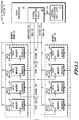
- FIG. 1 illustrates a data processing system 11 having a data processor 10, a memory bank 50, and a memory bank 55.
- Data processor 10 is coupled to memory bank 50 by way of busses 60 and 62 and by way of chip select conductor 64.
- Data processor 10 is coupled to memory bank 55 by way of busses 60 and 62 and by way of chip select conductor 65.
- bus 60 and bus 62 as being 32-bit busses, alternate embodiments of the present invention may use any number of conductors in each bus.
- Data processor 10 includes central processing unit (CPU) circuitry 12 and system integration circuitry 22 which are bi-directionally coupled by way of bus 24.
- Memory bank 50 includes memories 51-54
- memory bank 55 includes memories 56-59.
- data processor 10 and each one of memories 51-54 and 56-59 is implemented by way of a separate integrated circuit.
- all of data processing system 11 may be implemented on one integrated circuit.
- the present invention may be used to more equally distribute bus loading within a single integrated circuit, between integrated circuit on a board, or between more remotely distributed systems.
- memory 51 has a data port which is coupled to conductors [0-7] of bus 62 for receiving data bits [0-7]. Memory 51 also has an address port which is coupled to conductors [0-31] of bus 60. In addition, memory 51 has a chip select input which is coupled to conductor 64 for receiving a chip select signal. Memory 52 has a data port which is coupled to conductors [8-15] of bus 62 for receiving data bits [8-15]. Memory 52 also has an address port which is coupled to conductors [0-31] of bus 60. In addition, memory 52 has a chip select input which is coupled to conductor 64 for receiving a chip select signal.
- Memory 53 has a data port which is coupled to conductors [16-23] of bus 62 for receiving data bits [16-23]. Memory 53 also has an address port which is coupled to conductors [0-31] of bus 60. In addition, memory 53 has a chip select input which is coupled to conductor 64 for receiving a chip select signal. And, memory 54 has a data port which is coupled to conductors [24-31] of bus 62 for receiving data bits [24-31]. Memory 54 also has an address port which is coupled to conductors [0-31] of bus 60. In addition, memory 54 has a chip select input which is coupled to conductor 64 for receiving a chip select signal.
- memory 56 has a data port which is coupled to conductors [0-7] of bus 62 for receiving data bits [0-7].
- Memory 56 also has an address port which is coupled to conductors [0-31] of bus 60.
- memory 56 has a chip select input which is coupled to conductor 65 for receiving a chip select signal.
- Memory 57 has a data port which is coupled to conductors [8-15] of bus 62 for receiving data bits [8-15].
- Memory 57 also has an address port which is coupled to conductors [0-31] of bus 60.
- memory 57 has a chip select input which is coupled to conductor 65 for receiving a chip select signal.
- Memory 58 has a data port which is coupled to conductors [16-23] of bus 62 for receiving data bits [16-23]. Memory 58 also has an address port which is coupled to conductors [0-31] of bus 60. In addition, memory 58 has a chip select input which is coupled to conductor 65 for receiving a chip select signal. And, memory 59 has a data port which is coupled to conductors [24-31] of bus 62 for receiving data bits [24-31]. Memory 59 also has an address port which is coupled to conductors [0-31] of bus 60. In addition, memory 59 has a chip select input which is coupled to conductor 65 for receiving a chip select signal.
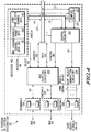
- FIG. 2 illustrates a data processing system 13 having a data processor 10, a memory bank 50, and a memory bank 55.
- Data processor 10 is coupled to memory bank 50 by way of busses 60 and 62 and by way of chip select conductor 64.
- Data processor 10 is coupled to memory bank 55 by way of busses 60 and 62 and by way of chip select conductor 65.
- Data processor 10 includes central processing unit (CPU) circuitry 12 and system integration circuitry 22 which are bi-directionally coupled by way of bus 24.
- Memory bank 50 includes memories 51-54
- memory bank 55 includes memories 56-59.
- data processor 10 and each one of memories 51-54 and 56-59 is implemented by way of a separate integrated circuit.
- all of data processing system 13 may be implemented on one integrated circuit.
- the present invention may be used to more equally distribute bus loading within a single integrated circuit, between integrated circuit on a board, or between more remotely distributed systems.
- Memory bank 50 in FIG. 2 is coupled to busses 60 and 62 in the same manner as memory bank 50 in FIG. 1.
- Memory 51 has a data port which is coupled to conductors [0-7] of bus 62 for receiving data bits [0-7].
- Memory 51 also has an address port which is coupled to conductors [0-31] of bus 60.
- memory 51 has a chip select input which is coupled to conductor 64 for receiving a chip select signal.
- Memory 52 has a data port which is coupled to conductors [8-15] of bus 62 for receiving data bits [8-15].
- Memory 52 also has an address port which is coupled to conductors [0-31] of bus 60.
- memory 52 has a chip select input which is coupled to conductor 64 for receiving a chip select signal.
- Memory 53 has a data port which is coupled to conductors [16-23] of bus 62 for receiving data bits [16-23]. Memory 53 also has an address port which is coupled to conductors [0-31] of bus 60. In addition, memory 53 has a chip select input which is coupled to conductor 64 for receiving a chip select signal. And, memory 54 has a data port which is coupled to conductors [24-31] of bus 62 for receiving data bits [24-31]. Memory 54 also has an address port which is coupled to conductors [0-31] of bus 60. In addition, memory 54 has a chip select input which is coupled to conductor 64 for receiving a chip select signal.
- memory bank 55 in FIG. 2 is coupled to busses 60 and 62 in a different manner than memory bank 55 in FIG. 1.
- the data ports of memories 56-59 are coupled to bus 62, while the address ports of memories 56-59 are coupled to bus 60.
- the role of bus 60 and bus 62 are reversed.
- the data ports of memories 56-59 are coupled to bus 60, while the address ports of memories 56-59 were coupled to bus 62.
- bus 60 transfers both address values and data values, namely address bits [0-31] and data bits (0-31].
- memory 56 has a data port which is coupled to conductors [0-7] of bus 60 for receiving data bits [0-7].
- Memory 56 also has an address port which is coupled to conductors [0-31] of bus 62.
- memory 56 has a chip select input which is coupled to conductor 65 for receiving a chip select signal.
- Memory 57 has a data port which is coupled to conductors [8-15] of bus 60 for receiving data bits [8-15].
- Memory 57 also has an address port which is coupled to conductors [0-31] of bus 62.
- memory 57 has a chip select input which is coupled to conductor 65 for receiving a chip select signal.
- Memory 58 has a data port which is coupled to conductors [16-23] of bus 60 for receiving data bits [16-23]. Memory 58 also has an address port which is coupled to conductors [0-31] of bus 62. In addition, memory 58 has a chip select input which is coupled to conductor 65 for receiving a chip select signal. And, memory 59 has a data port which is coupled to conductors [24-31] of bus 60 for receiving data bits [24-31]. Memory 59 also has an address port which is coupled to conductors [0-31] of bus 62. In addition, memory 59 has a chip select input which is coupled to conductor 65 for receiving a chip select signal.
- FIG. 3 illustrates a data processing system 15 having a data processor 10, a memory bank 50, a memory bank 55, an integrated circuit 70, and an integrated circuit 72.
- Memory banks 50 and 55 in FIG. 3 are coupled to busses 60 and 62 and chip select conductors 64-65 in the exact same manner as illustrated in FIG. 2 and described in the text above.
- Data processor 10 is coupled to memory bank 50 by way of busses 60 and 62 and by way of chip select conductor 64.
- Data processor 10 is coupled to memory bank 55 by way of busses 60 and 62 and by way of chip select conductor 65.
- Data processor 10 is coupled to integrated circuit 70 by way of bus 60 and by way of chip select conductor 66.
- a muxed address/data port of integrated circuit 70 communicates both address and data values by way of bus 60.
- Integrated circuit 70 is not coupled to and does not receive any address or data values by way of bus 62.
- Data processor 10 is coupled to integrated circuit 72 by way of bus 62 and by way of chip select conductor 67.
- a muxed address/data port of integrated circuit 72 communicates both address and data values by way of bus 62.
- Integrated circuit 70 is not coupled to and does not receive any address or data values by way of bus 60.
- Data processor 10 includes central processing unit (CPU) circuitry 12 and system integration circuitry 22 which are bi-directionally coupled by way of bus 24.
- Memory bank 50 includes memories 51-54, and memory bank 55 includes memories 56-59.
- data processor 10 and each one of memories 51-54 and 56-59 is implemented by way of a separate integrated circuit.
- all of data processing system 15 may be implemented on one integrated circuit.
- the present invention may be used to more equally distribute bus loading within a single integrated circuit, between integrated circuit on a board, or between more remotely distributed systems.
- data processor 10 is formed on a single integrated circuit.
- data processor 10 is a single chip microcontroller.
- data processor 10 may be implemented using any type of electrical circuitry.
- Memories 51-54 and 56-59 may be any type of memory.
- Alternate embodiments of data processing systems 11, 13, and 15 may include more, fewer, or different peripheral devices (51-54, 56-59, 70, and 72).
- busses 60 and 62 have been illustrated as 32-bit busses, alternate embodiment of the present invention may use any number of bits in busses 60 and 62.
- FIG. 4 illustrates a portion of system integration circuitry 22 of FIGS. 1-3 in accordance with one embodiment of the present invention.
- System integration circuitry 22 includes registers 80, bus coupling circuit 100, compare circuitry 101, control circuitry 102, chip select generation circuitry 104, terminals 124, terminals 126, and terminals 128.
- Bus 24 bi-directionally transfers address, data, and control information.
- Address bus 110 is the portion of bus 24 which provides address bits [0-31]
- data bus 112 is the portion of bus 24 which provides data bits [0-31]
- the control portion of bus 24 is provided to control circuitry 102.
- control circuitry 102 may provide external bus cycle control signals (e.g.
- Bus 24 is coupled to registers 80 in order for CPU 12 to perform read and write accesses to registers 80.
- Bus 24 is coupled to control circuitry 102 in order to provide and receive control information.
- Bus 24 is coupled to bus coupling circuit 100 by way of address bus 110 and data bus 112 in order to communicate address bits [0-31] and data bits [0-31].
- bus 24 is coupled to compare circuitry 101 to provide at least a portion of address bits [0-31].
- Registers 80 include register 84.
- Register 84 includes bus loading control bits 90, address range bits 150, and other chip select control bits 94. Bus loading control bits 90 are provided to bus coupling circuit 100 by way of conductors 114.
- Compare circuitry 101 is coupled to registers 80 to receive the address range bits 150, and possibly one or more of the other chip select control bits 94. Compare circuitry 101 provides compare results signals to control circuitry 102 by way of conductors 121.
- Control circuitry 102 provides control signals to bus coupling circuit 100 by way of conductors 116, and control circuitry 102 provides control signals to chip select generation circuitry 104 by way of conductors 118. Control circuitry 102 is bi-directionally coupled to registers 80.
- control circuitry 102 receives control bits from other chip select control bits 94 and provides status information back to other chip select control bits 94. Note that in alternate embodiments of the present invention, the functionality of control circuitry 102 and bus coupling circuit 100 may be combined into one circuit.
- Bus coupling circuit 100 is bi-directionally coupled to terminals 124 by way of bus 60.
- Bus coupling circuit 100 is bi-directionally coupled to terminals 126 by way of bus 62.
- Chip select generation circuitry 104 is bi-directionally coupled to terminals 128 by way of chip select conductors 64-67.
- the plurality of terminals 124 are used to provide bus 60 external to data processor 10.
- the plurality of terminals 126 are used to provide bus 62 external to data processor 10.
- the plurality of terminals 128 are used to provide chip select signals 64-67 external to data processor 10.
- Integrated circuit terminals 124, 126, and 128 may be any type of apparatus which allows electrical signals to be transferred to or from data processor 10.
- integrated circuit terminals 124, 126, and 128 may be integrated circuit pins, solder bumps, wire conductors, etc.
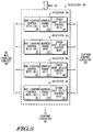
- FIG. 5 illustrates registers 80 of FIG. 4 in accordance with one embodiment of the present invention.
- registers 80 include a register 84, a register 85, a register 86, and a register 87. Each one of the registers 84-87 corresponds to one of the chip select signals 64-67, respectively.
- Register 84 includes bus loading control bits 90, address range bits 150, and other chip select control bits 94.
- Register 85 includes bus loading control bits 91, address range bits 151, and other chip select control bits 95.
- Register 86 includes bus loading control bits 92, address range bits 152, and other chip select control bits 96.
- register 87 includes bus loading control bits 93, address range bits 153, and other chip select control bits 97.
- Bus loading control bits 90-93 are provided to bus coupling circuit 100 by way of conductors 114.
- Compare circuitry 101 is coupled to registers 80 to receive the address range bits 150, and possibly one or more of the other chip select control bits 94.
- Control circuitry 102 is bi-directionally coupled to registers 84-87. In one embodiment of the present invention, control circuitry 102 receives control bits from other chip select control bits 94-97 and provides status information back to other chip select control bits 94-97.
- registers 80 include several register bit fields 90-93, 150-153, and 94-97, each of which includes a storage circuit for storing a control or status value.
- the register 84 illustrated in FIG. 4 includes at least three register fields (90, 150, and 94), alternate embodiments of the present invention may use more, fewer, or different register bit fields, and each register bit field may be used for control, status, or both control and status.
- alternate embodiment of the present invention may locate the bit fields 90-93, 150-153, and 94-97 in one or more separate registers.
- different embodiments of the present invention may include any numbers of bits for each of the register bits fields 90-93, 150-153, and 94-97 illustrated in FIG. 5.
- the control functionality of one or more of the register bit fields may be combined and encoded into fewer register bit fields.
- FIGS. 1-3 illustrate three different data processing systems 11, 13, and 15, respectively.
- Data processing systems 11, 13, and 15 all include the same data processor 10 and the same memory banks 50 and 55.
- Data processing system 15 (see FIG. 3) also includes integrated circuits 70 and 72, each of which requires a single multiplexed address/data bus.
- the primary difference between FIGS. 1, 2, and 3 is the manner in which the peripherals (e.g. memories 51-54 and 56-59) are coupled to data processor 10, and the bus loading mode which is selected by the bus loading control bits (e.g. see 90 in FIG. 4).
- the bits in registers 80 may be programmed by a write access from CPU 12. In alternate embodiments of the present invention, the bits in registers 80 may also be programmed by another bus master (e.g. integrated circuit 70 in FIG. 5).
- the bus loading control bits 90-93 select the bus loading mode in the following manner.
- each individual peripheral integrated circuit 51, 52, 53, 54, 56, 57, 58, 59, 70, and 72 illustrated in FIGS. 1-3 will represent an approximately equal bus load.
- memory 54 and integrated circuit 70 are each coupled to bus 60 [0:31], and therefore represent two loads on bus 60 [0:31].
- each data port of memories 51-54 and 56-59 is coupled to only 8-bits of a 32-bit bus; therefore as an example, in FIG. 1 memories 51-54 represent only one load on bus 62 [0:31].
- bus loading of busses 60 and 62 is as follows for FIGS. 1-3.
- Bus 60 [0:31] has eight loads, while bus 62 [0:31] has only two loads.
- bus 60 each 32-bit address port of memories 51-54 and 56-59 is coupled to all 32-bits of bus 60.
- bus 62 bus 62 [0:31] has only two loads because the 8-bit data ports of only two of memories 51-54 and 56-59 are coupled to each 8-bits of bus 60.
- memory bank 50 is selected by chip select signal 64.
- Register 84 which corresponds to chip select signal 64, is used to determine the bus loading mode (bits 90), the address range (bits 150) and the other characteristics (bits 94) of chip select signal 64 and accesses to memory bank 50.
- Memory bank 55 is selected by chip select signal 65.
- Register 85 which corresponds to chip select signal 65, is used to determine the bus loading mode (bits 91), the address range (bits 151) and the other characteristics (bits 95) of chip select signal 65 and accesses to memory bank 55.
- bus loading mode bits 90 are programmed to %00 so that accesses to memory bank 50 use bus 60 [0:31] as the address bus to transfer the address value [0:31] and use bus 62 [0:31] as the data bus to transfer the data value [0:31].
- Bus loading mode bits 91 are programmed to %00 so that accesses to memory bank 55 use bus 60 [0:31] as the address bus to transfer the address value [0:31] and use bus 62 [0:31] as the data bus to transfer the data value [0:31].
- bus 60 is only used to transfer 32-bit address values
- bus 62 is only used to transfer 32-bit data values.
- Data processing system 11 therefore functions in a similar manner to a prior art data processing system which uses dedicated address and data busses.
- bus 60 as a dedicated address bus and bus 62 as a dedicated data bus
- the bus loading on bus 60 i.e. eight loads
- bus 62 i.e. two loads
- Data processing system 13 illustrates how the present invention may be used to balance the bus loading on busses 60 and 62.
- Data processing system 13 in FIG. 2 may use the same memory banks 50 and 55 and the same data processor 10 as in FIG. 1.
- the present invention allows the functionality of busses 60 and 62 to be changed for different bus cycles.
- bus loading mode bits 90 are programmed to %00 so that accesses to memory bank 50 use bus 60 [0:31] as the address bus to transfer the address value [0:31] and use bus 62 [0:31] as the data bus to transfer the data value [0:31].
- Bus loading mode bits 91 are programmed to %11 so that accesses to memory bank 55 use bus 62 [0:31] as the address bus to transfer the address value [0:31] and use bus 60 [0:31] as the data bus to transfer the data value [0:31].
- bus 60 may be used to transfer 32-bit address values or 32-bit data values
- bus 62 may be used to transfer 32-bit address values or 32-bit data values.
- Data processing system 13 thus does not use dedicated address and data busses.
- the bus loading on bus 60 i.e. five loads
- the bus loading on bus 62 may be equalized to the bus loading on bus 62 (i.e. five loads).
- bus 60 [0:31] has five loads
- bus 62 [0:31] also has five loads.
- each 32-bit address port of memories 51-54 is coupled to all 32-bits of bus 60
- the data port of only one of memories 56-59 is coupled to each 8-bits of bus 60.
- bus 62 [0:31] has five loads because each 32-bit address port of memories 56-59 is coupled to all 32-bits of bus 62, and the data port of only one of memories 51-54 is coupled to each 8-bits of bus 62).
- memory bank 50 is selected by chip select signal 64.
- Register 84 which corresponds to chip select signal 64, is used to determine the bus loading mode (bits 90), the address range (bits 150) and the other characteristics (bits 94) of chip select signal 64 and accesses to memory bank 50.
- Memory bank 55 is selected by chip select signal 65.
- Register 85 which corresponds to chip select signal 65, is used to determine the bus loading mode (bits 91), the address range (bits 151) and the other characteristics (bits 95) of chip select signal 65 and accesses to memory bank 55.
- Data processing system 15 illustrates how the present invention may be used to balance the bus loading on busses 60 and 62 if both non-multiplexed peripherals (e.g. memories 51-54 and 56-59) are used along with multiplexed peripherals (e.g. integrated circuits 70 and 72).
- Data processing system 15 in FIG. 3 may use the same memory banks 50 and 55 and the same data processor 10 as in FIG. 1.
- the present invention allows the functionality of busses 60 and 62 to be changed for different bus cycles.
- bus loading mode bits 90 are programmed to %00 so that accesses to memory bank 50 use bus 60 [0:31] as the address bus to transfer the address value [0:31] and use bus 62 [0:31] as the data bus to transfer the data value [0:31].
- Bus loading mode bits 91 are programmed to %11 so that accesses to memory bank 55 use bus 62 [0:31] as the address bus to transfer the address value [0:31] and use bus 60 [0:31] as the data bus to transfer the data value [0:31].
- Bus loading mode bits 92 are programmed to %01 so that accesses to integrated circuit 70 use bus 60 [0:31] in a multiplexed fashion as both the address and data bus to transfer both the address value [0:31] and the data value [0:31].
- Bus 62 [0:31] is not used at all for accesses to integrated circuit 70.
- Bus loading mode bits 93 are programmed to %10 so that accesses to integrated circuit 72 use bus 62 [0:31] in a multiplexed fashion as both the address and data bus to transfer both the address value [0:31] and the data value [0:31].
- Bus 60 [0:31] is not used at all for accesses to integrated circuit 72.
- bus 60 may be used to transfer non-multiplexed address values, non-multiplexed data values, multiplexed address and data values, or no values at all
- bus 62 may be used to transfer non-multiplexed address values, non-multiplexed data values, multiplexed address and data values, or no values at all.
- Data processing system 15 thus does not use dedicated address and data busses, and does not use dedicated non-multiplexed or multiplexed busses. And as a result, the bus loading on bus 60 (i.e. six loads) may be equalized to the bus loading on bus 62 (i.e. six loads).
- data processing system 15 also has much more equal bus loading than data processing system 11 of FIG. 1.
- Bus 60 [0:31] has six loads
- bus 62 [0:31] also has six loads.
- the memories 51-54 and 56-59 are coupled to busses 60 and 62 in the same manner as for data processing system 13 in FIG. 2.
- data processing system 15 in FIG. 3 illustrates how two multiplexed peripheral devices 70 and 72 may be added to a data processing system 15 without interfering with the balanced bus loading achieved in FIG. 2.
- bus 60 in addition to the same five loads from FIG. 2, bus 60 in FIG. 3 also has a sixth load because the muxed address/data port of integrated circuit 70 is coupled to all 32-bits of bus 60.
- bus 62 in FIG. 3 also has a sixth load because the muxed address/data port of integrated circuit 72 is coupled to all 32-bits of bus 62.
- memory bank 50 is selected by chip select signal 64.
- Register 84 which corresponds to chip select signal 64, is used to determine the bus loading mode (bits 90), the address range (bits 150) and the other characteristics (bits 94) of chip select signal 64 and accesses to memory bank 50.
- Memory bank 55 is selected by chip select signal 65.
- Register 85 which corresponds to chip select signal 65, is used to determine the bus loading mode (bits 91), the address range (bits 151) and the other characteristics (bits 95) of chip select signal 65 and accesses to memory bank 50.
- Register 86 which corresponds to chip select signal 66, is used to determine the bus loading mode (bits 92), the address range (bits 152) and the other characteristics (bits 96) of chip select signal 66 and accesses to integrated circuit 70.
- Register 87 which corresponds to chip select signal 67, is used to determine the bus loading mode (bits 93), the address range (bits 153) and the other characteristics (bits 97) of chip select signal 67 and accesses to integrated circuit 72.
- CPU 12 (see FIGS. 1-3) is capable of initiating an external bus cycle.
- An external bus cycle is a bus cycle that is driven external to data processor 10 by way of busses 60 and 62.
- CPU 12 initiates an external bus cycle by driving an address value, a corresponding data value, and appropriate control signals on bus 24.
- Compare circuitry 101 receives the address value from bus 24 and the address range bits 150-153 from registers 80. Compare circuitry 101 then determines which address range the received address value is associated with. In one embodiment of the present invention, compare circuitry 101 compares at least a portion of the address value from bus 24 to each set of address range bits 150-153 from registers 80. Address range bits 150 may use any method and any number of bit fields to specify an address range.
- Compare circuitry 101 then transfers control signals 121 to control circuitry 102.
- Control signals 121 indicate to control circuitry 102 which address range, and thus which chip select and which one of registers 80, will be used.
- Control circuitry 102 then sends control signals 118 to chip select generation circuitry 104 to select which chip select signal is to be asserted.
- Control circuitry 102 also sends control signals to register 80 by way of conductors 122 to select which one of registers 80 will be used. For example, if the received address value was in the address range specified by address range bits 150, control circuitry 102 will select register 84 and will receive the other chip select control bits 94 by way of conductors 122.
- the bus loading control bits 90 will be provided to bus coupling circuitry 100 by way of select conductors 114.
- Control circuitry 102 may provided timing or other control information to bus coupling circuit 100 by way of conductors 116.
- bus coupling circuitry 100 determines whether to couple the address conductors 110 of bus 24 to bus 60 or to bus 62. Likewise, based on the bus loading control bits 90, bus coupling circuitry determines whether to couple the data conductors 112 of bus 24 to bus 60 or to bus 62. In addition, bus loading control bits 90 determine whether bus coupling circuitry 100 provides the address and data values on the same bus (i.e. multiplexed on one of busses 60 or 62) or on different busses (i.e. non-multiplexed on both busses 60 and 62).
- the plurality of terminals 124 are used to provide bus 60 external to data processor 10.
- the plurality of terminals 126 are used to provide bus 62 external to data processor 10.
- the plurality of terminals 128 are used to provide chip select signals 64-67 external to data processor 10.
Abstract
Method and apparatus for distributing bus loading in a data processing system (11, 13, 15). In one embodiment, the present invention uses a bus loading control register bit field (90) to determine how address and data will be transferred over busses (60, 62) in order to allow more equal distribution of loads on the busses (60, 62). There is no fixed address bus or data bus. Instead, on a per cycle basis, each generic bus (60, 62) can be individually programmed to transfer address only, data only, both address and data, or neither address nor data. In one embodiment, there is a programmable address range (150-153) which corresponds to each bus loading bit field (90-93). For a bus access to a particular address range, the corresponding bus loading bit field (e.g. 90) is used to determine how address and data are transferred across the busses (60, 62).
Description
- The present application is related to the following U.S. patent applications:
- "Method And Apparatus To Perform Bus Reflection Operation Using A Data Processor", invented by William C. Moyer, having attorney docket number SC-02712A, filed March 1995, and assigned to the assignee hereof;
- "Method And Apparatus For Performing Multiplexed and Non-multiplexed Bus Cycles In A Data Processing System", invented by Oded Yishay et al., having serial number 08/158,584, filed November 29, 1993, and assigned to the assignee hereof;
- "Method And Apparatus In A Data Processing System For Selectively Inserting Bus Cycle Idle Time", invented by Oded Yishay et al., having serial number 08/158,575, filed November 29, 1993, and assigned to the assignee hereof;
- "Integrated Circuit Microprocessor With Chip Select Logic", invented by James B. Eifert et al., having serial number 07/432,423, filed November 6, 1989, and assigned to the assignee hereof;
- "Data Processor With Controlled Burst Memory Accesses And Method Thereof", invented by Le et al., having serial number 08/363,423, and filed December 21, 1994;
- "Modular Chip Select Control Circuit And Method For Performing Pipelined Memory Accesses", invented by Le et al., having serial number 08/298,868, and filed August 31, 1994;
- "Integrated Circuit Microprocessor With Programmable Memory Access Interface Types", invented by Le et al., having serial number 08/298,892, and filed August 31, 1994;
- "Method for Synchronously Accessing Memory", invented by Le et al., having serial number 08/353,764, and filed December 12, 1994;
- "Programmable Pin Configuration Logic Circuit For Providing A Chip Select Signal And Related Method", invented by Le et al., having serial number 08/298,638, and filed August 31, 1994; and
- "Method for Synchronously Accessing Memory", invented by Le et al., having serial number 08/298,885, and filed August 31, 1994.
- The present invention relates in general to a data processing system, and more particularly to a method and apparatus for distributing bus loading in a data processing system.
- The amount of loading on a bus in a data processing system is important to the performance of the data processing system. Most data processing systems have a maximum bus loading (i.e. a maximum resistive and capacitive loading) which each bus can drive and still meet the required voltage and timing specifications for that bus. In addition, even if the loading on a bus is below the maximum specified value, the more loading on a bus, the slower the bus will operate. If multiple busses are used in a data processing system (e.g. a separate address bus and a separate data bus), it is desirable to not have a much greater load on one bus than on the other busses.
- A data processor, such as a microcomputer integrated circuit, is used with a wide range of peripheral devices, for example memory integrated circuits and application specific integrated circuits (ASICs) in a data processing system. Some peripheral devices use multiplexed address and data busses, and some peripheral devices use non-multiplexed address and data busses. In addition, some peripherals may act only as bus slaves, while other peripherals may act as either bus slaves or bus masters.
- It is not uncommon for a data processing system to have unequally loaded busses (e.g. address and data busses) because of the particular configuration of peripheral devices which are coupled to the data processor. A solution was needed which would more evenly distribute bus loading between various busses in a data processing system, without adding significant cost to the system.
-
- FIG. 1 illustrates, in block diagram form, a
data processing system 11 in accordance with one embodiment of the present invention; - FIG. 2 illustrates, in block diagram form, a
data processing system 13 in accordance with an alternate embodiment of the present invention; - FIG. 3 illustrates, in block diagram form, a
data processing system 15 in accordance with an alternate embodiment of the present invention; - FIG. 4 illustrates, in block diagram form, a portion of
system integration circuitry 22 of FIGS. 1-3 in accordance with one embodiment of the present invention; and - FIG. 5 illustrates, in block diagram form,
registers 80 of FIG. 4 in accordance with one embodiment of the present invention. - The present invention allows more even distribution of bus loading between various busses in a data processing system, without adding significant cost to the system.
- Referring to FIG. 4, in one embodiment, the present invention uses a bus loading control
register bit field 90 to determine how address and data will be transferred overbusses busses generic bus control registers 80 only need to be programmed once out of reset, back to back bus cycles can usebusses - Referring to FIG. 5, in one embodiment of the present invention, there is a programmable address range 150-153 which corresponds to each bus loading control register bit field 90-93. For a bus access to a particular address range, the corresponding bus loading control register bit field (e.g. 90) is used to determine how address and data are transferred across the
busses - In addition, the present invention may be used to minimize the interconnect required between a data processor and its associated peripherals without requiring the addition of any "glue logic" between the data processor and the peripherals.
- The term "bus" will be used to refer to a plurality of signals or conductors which may be used to transfer one or more various types of information, such as data, addresses, control, or status. The terms "assert" and "negate" will be used when referring to the rendering of a signal, status bit, or similar apparatus into its logically true or logically false state, respectively. If the logically true state is a logic level one, the logically false state will be a logic level zero. And if the logically true state is a logic level zero, the logically false state will be a logic level one.
- Brackets will be used to indicate the conductors of a bus or the bit locations of a value. For example, "bus 60 [0-7]" or "conductors [0-7] of
bus 60" indicates the eight lower order conductors ofbus 60, and "address bits [0-7]" or "ADDRESS [0-7]" indicates the eight lower order bits of an address value. The symbol "$" preceding a number indicates that the number is represented in its hexadecimal or base sixteen form. The symbol "%" preceding a number indicates that the number is represented in its binary or base two form. - FIG. 1 illustrates a
data processing system 11 having adata processor 10, amemory bank 50, and amemory bank 55.Data processor 10 is coupled tomemory bank 50 by way ofbusses select conductor 64.Data processor 10 is coupled tomemory bank 55 by way ofbusses select conductor 65. Although the embodiments of the present invention illustrated in FIGS. 1-4 illustratebus 60 andbus 62 as being 32-bit busses, alternate embodiments of the present invention may use any number of conductors in each bus. -
Data processor 10 includes central processing unit (CPU)circuitry 12 andsystem integration circuitry 22 which are bi-directionally coupled by way ofbus 24.Memory bank 50 includes memories 51-54, andmemory bank 55 includes memories 56-59. In one embodiment of the present invention,data processor 10 and each one of memories 51-54 and 56-59 is implemented by way of a separate integrated circuit. In alternate embodiments of the present invention, all ofdata processing system 11 may be implemented on one integrated circuit. The present invention may be used to more equally distribute bus loading within a single integrated circuit, between integrated circuit on a board, or between more remotely distributed systems. - Still referring to FIG. 1,
memory 51 has a data port which is coupled to conductors [0-7] ofbus 62 for receiving data bits [0-7].Memory 51 also has an address port which is coupled to conductors [0-31] ofbus 60. In addition,memory 51 has a chip select input which is coupled toconductor 64 for receiving a chip select signal.Memory 52 has a data port which is coupled to conductors [8-15] ofbus 62 for receiving data bits [8-15].Memory 52 also has an address port which is coupled to conductors [0-31] ofbus 60. In addition,memory 52 has a chip select input which is coupled toconductor 64 for receiving a chip select signal.Memory 53 has a data port which is coupled to conductors [16-23] ofbus 62 for receiving data bits [16-23].Memory 53 also has an address port which is coupled to conductors [0-31] ofbus 60. In addition,memory 53 has a chip select input which is coupled toconductor 64 for receiving a chip select signal. And,memory 54 has a data port which is coupled to conductors [24-31] ofbus 62 for receiving data bits [24-31].Memory 54 also has an address port which is coupled to conductors [0-31] ofbus 60. In addition,memory 54 has a chip select input which is coupled toconductor 64 for receiving a chip select signal. - Similarly,
memory 56 has a data port which is coupled to conductors [0-7] ofbus 62 for receiving data bits [0-7].Memory 56 also has an address port which is coupled to conductors [0-31] ofbus 60. In addition,memory 56 has a chip select input which is coupled toconductor 65 for receiving a chip select signal.Memory 57 has a data port which is coupled to conductors [8-15] ofbus 62 for receiving data bits [8-15].Memory 57 also has an address port which is coupled to conductors [0-31] ofbus 60. In addition,memory 57 has a chip select input which is coupled toconductor 65 for receiving a chip select signal.Memory 58 has a data port which is coupled to conductors [16-23] ofbus 62 for receiving data bits [16-23].Memory 58 also has an address port which is coupled to conductors [0-31] ofbus 60. In addition,memory 58 has a chip select input which is coupled toconductor 65 for receiving a chip select signal. And,memory 59 has a data port which is coupled to conductors [24-31] ofbus 62 for receiving data bits [24-31].Memory 59 also has an address port which is coupled to conductors [0-31] ofbus 60. In addition,memory 59 has a chip select input which is coupled toconductor 65 for receiving a chip select signal. - Referring now to FIG. 2, FIG. 2 illustrates a
data processing system 13 having adata processor 10, amemory bank 50, and amemory bank 55.Data processor 10 is coupled tomemory bank 50 by way ofbusses select conductor 64.Data processor 10 is coupled tomemory bank 55 by way ofbusses select conductor 65. -
Data processor 10 includes central processing unit (CPU)circuitry 12 andsystem integration circuitry 22 which are bi-directionally coupled by way ofbus 24.Memory bank 50 includes memories 51-54, andmemory bank 55 includes memories 56-59. In one embodiment of the present invention,data processor 10 and each one of memories 51-54 and 56-59 is implemented by way of a separate integrated circuit. In alternate embodiments of the present invention, all ofdata processing system 13 may be implemented on one integrated circuit. The present invention may be used to more equally distribute bus loading within a single integrated circuit, between integrated circuit on a board, or between more remotely distributed systems. -
Memory bank 50 in FIG. 2 is coupled tobusses memory bank 50 in FIG. 1.Memory 51 has a data port which is coupled to conductors [0-7] ofbus 62 for receiving data bits [0-7].Memory 51 also has an address port which is coupled to conductors [0-31] ofbus 60. In addition,memory 51 has a chip select input which is coupled toconductor 64 for receiving a chip select signal.Memory 52 has a data port which is coupled to conductors [8-15] ofbus 62 for receiving data bits [8-15].Memory 52 also has an address port which is coupled to conductors [0-31] ofbus 60. In addition,memory 52 has a chip select input which is coupled toconductor 64 for receiving a chip select signal.Memory 53 has a data port which is coupled to conductors [16-23] ofbus 62 for receiving data bits [16-23].Memory 53 also has an address port which is coupled to conductors [0-31] ofbus 60. In addition,memory 53 has a chip select input which is coupled toconductor 64 for receiving a chip select signal. And,memory 54 has a data port which is coupled to conductors [24-31] ofbus 62 for receiving data bits [24-31].Memory 54 also has an address port which is coupled to conductors [0-31] ofbus 60. In addition,memory 54 has a chip select input which is coupled toconductor 64 for receiving a chip select signal. - Note that
memory bank 55 in FIG. 2 is coupled tobusses memory bank 55 in FIG. 1. In FIG. 1, the data ports of memories 56-59 are coupled tobus 62, while the address ports of memories 56-59 are coupled tobus 60. However, in FIG. 2, the role ofbus 60 andbus 62 are reversed. In FIG. 2, the data ports of memories 56-59 are coupled tobus 60, while the address ports of memories 56-59 were coupled tobus 62. Thus indata processing system 13,bus 60 transfers both address values and data values, namely address bits [0-31] and data bits (0-31]. - Still referring to FIG. 2,
memory 56 has a data port which is coupled to conductors [0-7] ofbus 60 for receiving data bits [0-7].Memory 56 also has an address port which is coupled to conductors [0-31] ofbus 62. In addition,memory 56 has a chip select input which is coupled toconductor 65 for receiving a chip select signal.Memory 57 has a data port which is coupled to conductors [8-15] ofbus 60 for receiving data bits [8-15].Memory 57 also has an address port which is coupled to conductors [0-31] ofbus 62. In addition,memory 57 has a chip select input which is coupled toconductor 65 for receiving a chip select signal.Memory 58 has a data port which is coupled to conductors [16-23] ofbus 60 for receiving data bits [16-23].Memory 58 also has an address port which is coupled to conductors [0-31] ofbus 62. In addition,memory 58 has a chip select input which is coupled toconductor 65 for receiving a chip select signal. And,memory 59 has a data port which is coupled to conductors [24-31] ofbus 60 for receiving data bits [24-31].Memory 59 also has an address port which is coupled to conductors [0-31] ofbus 62. In addition,memory 59 has a chip select input which is coupled toconductor 65 for receiving a chip select signal. - Referring now to FIG. 3, FIG. 3 illustrates a
data processing system 15 having adata processor 10, amemory bank 50, amemory bank 55, an integrated circuit 70, and anintegrated circuit 72.Memory banks busses -
Data processor 10 is coupled tomemory bank 50 by way ofbusses select conductor 64.Data processor 10 is coupled tomemory bank 55 by way ofbusses select conductor 65.Data processor 10 is coupled to integrated circuit 70 by way ofbus 60 and by way of chipselect conductor 66. A muxed address/data port of integrated circuit 70 communicates both address and data values by way ofbus 60. Integrated circuit 70 is not coupled to and does not receive any address or data values by way ofbus 62.Data processor 10 is coupled to integratedcircuit 72 by way ofbus 62 and by way of chipselect conductor 67. A muxed address/data port ofintegrated circuit 72 communicates both address and data values by way ofbus 62. Integrated circuit 70 is not coupled to and does not receive any address or data values by way ofbus 60. -
Data processor 10 includes central processing unit (CPU)circuitry 12 andsystem integration circuitry 22 which are bi-directionally coupled by way ofbus 24.Memory bank 50 includes memories 51-54, andmemory bank 55 includes memories 56-59. In one embodiment of the present invention,data processor 10 and each one of memories 51-54 and 56-59 is implemented by way of a separate integrated circuit. In alternate embodiments of the present invention, all ofdata processing system 15 may be implemented on one integrated circuit. The present invention may be used to more equally distribute bus loading within a single integrated circuit, between integrated circuit on a board, or between more remotely distributed systems. - Referring to FIGS. 1-3, in some embodiments of the present invention,
data processor 10 is formed on a single integrated circuit. In some embodiment,data processor 10 is a single chip microcontroller. In alternate embodiments,data processor 10 may be implemented using any type of electrical circuitry. Memories 51-54 and 56-59 may be any type of memory. Alternate embodiments ofdata processing systems busses busses - Referring now to FIG. 4, FIG. 4 illustrates a portion of
system integration circuitry 22 of FIGS. 1-3 in accordance with one embodiment of the present invention.System integration circuitry 22 includesregisters 80,bus coupling circuit 100, comparecircuitry 101,control circuitry 102, chipselect generation circuitry 104,terminals 124,terminals 126, andterminals 128.Bus 24 bi-directionally transfers address, data, and control information.Address bus 110 is the portion ofbus 24 which provides address bits [0-31],data bus 112 is the portion ofbus 24 which provides data bits [0-31], and the control portion ofbus 24 is provided to controlcircuitry 102. Note that in some embodiments of the present invention,control circuitry 102 may provide external bus cycle control signals (e.g. address strobe, data strobe, write enable, column address strobe, row address strobe, read/write, etc.) external todata processor 10 by way of one or more terminals (not shown).Bus 24 is coupled toregisters 80 in order forCPU 12 to perform read and write accesses to registers 80.Bus 24 is coupled to controlcircuitry 102 in order to provide and receive control information.Bus 24 is coupled tobus coupling circuit 100 by way ofaddress bus 110 anddata bus 112 in order to communicate address bits [0-31] and data bits [0-31]. And,bus 24 is coupled to comparecircuitry 101 to provide at least a portion of address bits [0-31]. -
Registers 80 includeregister 84.Register 84 includes busloading control bits 90, address rangebits 150, and other chipselect control bits 94. Busloading control bits 90 are provided tobus coupling circuit 100 by way ofconductors 114. Comparecircuitry 101 is coupled toregisters 80 to receive theaddress range bits 150, and possibly one or more of the other chipselect control bits 94. Comparecircuitry 101 provides compare results signals to controlcircuitry 102 by way ofconductors 121.Control circuitry 102 provides control signals tobus coupling circuit 100 by way ofconductors 116, andcontrol circuitry 102 provides control signals to chipselect generation circuitry 104 by way ofconductors 118.Control circuitry 102 is bi-directionally coupled to registers 80. In one embodiment of the present invention,control circuitry 102 receives control bits from other chipselect control bits 94 and provides status information back to other chipselect control bits 94. Note that in alternate embodiments of the present invention, the functionality ofcontrol circuitry 102 andbus coupling circuit 100 may be combined into one circuit. -
Bus coupling circuit 100 is bi-directionally coupled toterminals 124 by way ofbus 60.Bus coupling circuit 100 is bi-directionally coupled toterminals 126 by way ofbus 62. Chipselect generation circuitry 104 is bi-directionally coupled toterminals 128 by way of chip select conductors 64-67. The plurality ofterminals 124 are used to providebus 60 external todata processor 10. The plurality ofterminals 126 are used to providebus 62 external todata processor 10. And, the plurality ofterminals 128 are used to provide chip select signals 64-67 external todata processor 10. -
Integrated circuit terminals data processor 10. For example, integratedcircuit terminals - Referring now to FIG. 5, FIG. 5 illustrates
registers 80 of FIG. 4 in accordance with one embodiment of the present invention. In one embodiment of the present invention, registers 80 include aregister 84, aregister 85, aregister 86, and aregister 87. Each one of the registers 84-87 corresponds to one of the chip select signals 64-67, respectively.Register 84 includes busloading control bits 90, address rangebits 150, and other chipselect control bits 94.Register 85 includes busloading control bits 91, address rangebits 151, and other chipselect control bits 95.Register 86 includes busloading control bits 92, address rangebits 152, and other chipselect control bits 96. And, register 87 includes busloading control bits 93, address rangebits 153, and other chipselect control bits 97. Bus loading control bits 90-93 are provided tobus coupling circuit 100 by way ofconductors 114. Comparecircuitry 101 is coupled toregisters 80 to receive theaddress range bits 150, and possibly one or more of the other chipselect control bits 94.Control circuitry 102 is bi-directionally coupled to registers 84-87. In one embodiment of the present invention,control circuitry 102 receives control bits from other chip select control bits 94-97 and provides status information back to other chip select control bits 94-97. - In one embodiment of the present invention, registers 80 include several register bit fields 90-93, 150-153, and 94-97, each of which includes a storage circuit for storing a control or status value. Although the
register 84 illustrated in FIG. 4 includes at least three register fields (90, 150, and 94), alternate embodiments of the present invention may use more, fewer, or different register bit fields, and each register bit field may be used for control, status, or both control and status. In addition, alternate embodiment of the present invention may locate the bit fields 90-93, 150-153, and 94-97 in one or more separate registers. Also, different embodiments of the present invention may include any numbers of bits for each of the register bits fields 90-93, 150-153, and 94-97 illustrated in FIG. 5. In some embodiments of the present invention, the control functionality of one or more of the register bit fields may be combined and encoded into fewer register bit fields. - The operation of the present invention will now be discussed. FIGS. 1-3 illustrate three different
data processing systems Data processing systems same data processor 10 and thesame memory banks integrated circuits 70 and 72, each of which requires a single multiplexed address/data bus. The primary difference between FIGS. 1, 2, and 3 is the manner in which the peripherals (e.g. memories 51-54 and 56-59) are coupled todata processor 10, and the bus loading mode which is selected by the bus loading control bits (e.g. see 90 in FIG. 4). The bits inregisters 80 may be programmed by a write access fromCPU 12. In alternate embodiments of the present invention, the bits inregisters 80 may also be programmed by another bus master (e.g. integrated circuit 70 in FIG. 5). - The bus loading control bits 90-93 (see FIG. 5) select the bus loading mode in the following manner.
- (used if the address for a bus cycle is within the address range defined by the address range bits 150)
- %00 -
- bus 60 [0:31] serves as the address bus; and bus 62 [0:31] serves as the data bus.
- %01 -
- bus 60 [0:31] serves as both the address and data bus.
- %10 -
- bus 62 [0:31] serves as both the address and data bus.
- %11 -
- bus 62 [0:31] serves as the address bus; and bus 60 [0:31] serves as the data bus.
- (used if the address for a bus cycle is within the address range defined by the address range bits 151)
- %00 -
- bus 60 [0:31] serves as the address bus; and bus 62 [0:31] serves as the data bus.
- %01 -
- bus 60 [0:31] serves as both the address and data bus.
- %10 -
- bus 62 [0:31] serves as both the address and data bus.
- %11 -
- bus 62 [0:31] serves as the address bus; and bus 60 [0:31] serves as the data bus.
- (used if the address for a bus cycle is within the address range defined by the address range bits 152)
- %00 -
- bus 60 [0:31] serves as the address bus; and bus 62 [0:31] serves as the data bus.
- %01 -
- bus 60 [0:31] serves as both the address and data bus.
- %10 -
- bus 62 [0:31] serves as both the address and data bus.
- %11 -
- bus 62 [0:31] serves as the address bus; and bus 60 [0:31] serves as the data bus.
- (used if the address for a bus cycle is within the address range defined by the address range bits 153)
- %00 -
- bus 60 [0:31] serves as the address bus; and bus 62 [0:31] serves as the data bus.
- %01 -
- bus 60 [0:31] serves as both the address and data bus.
- %10 -
- bus 62 [0:31] serves as both the address and data bus.
- %11 -
- bus 62 [0:31] serves as the address bus; and bus 60 [0:31] serves as the data bus.
- For the purpose of discussion, each individual peripheral
integrated circuit memory 54 and integrated circuit 70 are each coupled to bus 60 [0:31], and therefore represent two loads on bus 60 [0:31]. In determining bus loading, it is important to note that each data port of memories 51-54 and 56-59 is coupled to only 8-bits of a 32-bit bus; therefore as an example, in FIG. 1 memories 51-54 represent only one load on bus 62 [0:31]. - The bus loading of
busses - FIG. 1:
-
data processing system 11
bus 60 [0:31] has eight loads
bus 62 [0:31] has two loads - FIG. 2:
-
data processing system 13
bus 60 [0:31] has five loads
bus 62 [0:31] has five loads - FIG. 3:
-
data processing system 15
bus 60 [0:31] has six loads
bus 62 [0:31] has six loads - Referring to FIG. 1,
data processing system 11 has very unbalanced bus loading. Bus 60 [0:31] has eight loads, while bus 62 [0:31] has only two loads. Referring tobus 60, each 32-bit address port of memories 51-54 and 56-59 is coupled to all 32-bits ofbus 60. And referring tobus 62, bus 62 [0:31] has only two loads because the 8-bit data ports of only two of memories 51-54 and 56-59 are coupled to each 8-bits ofbus 60. - Referring to FIG. 1 and FIG. 5,
memory bank 50 is selected by chipselect signal 64.Register 84, which corresponds to chipselect signal 64, is used to determine the bus loading mode (bits 90), the address range (bits 150) and the other characteristics (bits 94) of chipselect signal 64 and accesses tomemory bank 50.Memory bank 55 is selected by chipselect signal 65.Register 85, which corresponds to chipselect signal 65, is used to determine the bus loading mode (bits 91), the address range (bits 151) and the other characteristics (bits 95) of chipselect signal 65 and accesses tomemory bank 55. - Referring to FIG. 1, bus
loading mode bits 90 are programmed to %00 so that accesses tomemory bank 50 use bus 60 [0:31] as the address bus to transfer the address value [0:31] and use bus 62 [0:31] as the data bus to transfer the data value [0:31]. Busloading mode bits 91 are programmed to %00 so that accesses tomemory bank 55 use bus 60 [0:31] as the address bus to transfer the address value [0:31] and use bus 62 [0:31] as the data bus to transfer the data value [0:31]. Thus, for thedata processing system 11 illustrated in FIG. 1,bus 60 is only used to transfer 32-bit address values, andbus 62 is only used to transfer 32-bit data values.Data processing system 11 therefore functions in a similar manner to a prior art data processing system which uses dedicated address and data busses. Unfortunately, however, by usingbus 60 as a dedicated address bus andbus 62 as a dedicated data bus, the bus loading on bus 60 (i.e. eight loads) is much greater than the bus loading on bus 62 (i.e. two loads). - Data processing system 13 (see FIG. 2) illustrates how the present invention may be used to balance the bus loading on
busses Data processing system 13 in FIG. 2 may use thesame memory banks same data processor 10 as in FIG. 1. However, in FIG. 2, the present invention allows the functionality ofbusses - Referring to FIG. 2, bus
loading mode bits 90 are programmed to %00 so that accesses tomemory bank 50 use bus 60 [0:31] as the address bus to transfer the address value [0:31] and use bus 62 [0:31] as the data bus to transfer the data value [0:31]. Busloading mode bits 91 are programmed to %11 so that accesses tomemory bank 55 use bus 62 [0:31] as the address bus to transfer the address value [0:31] and use bus 60 [0:31] as the data bus to transfer the data value [0:31]. Thus, for thedata processing system 13 illustrated in FIG. 2,bus 60 may be used to transfer 32-bit address values or 32-bit data values, andbus 62 may be used to transfer 32-bit address values or 32-bit data values.Data processing system 13 thus does not use dedicated address and data busses. And as a result, the bus loading on bus 60 (i.e. five loads) may be equalized to the bus loading on bus 62 (i.e. five loads). - Referring to FIG. 2,
data processing system 13 has much more equal bus loading thandata processing system 11 of FIG. 1. Bus 60 [0:31] has five loads, and bus 62 [0:31] also has five loads. Referring tobus 60, each 32-bit address port of memories 51-54 is coupled to all 32-bits ofbus 60, and the data port of only one of memories 56-59 is coupled to each 8-bits ofbus 60. And similarly, referring tobus 62, bus 62 [0:31] has five loads because each 32-bit address port of memories 56-59 is coupled to all 32-bits ofbus 62, and the data port of only one of memories 51-54 is coupled to each 8-bits of bus 62). - Referring to FIG. 2 and FIG. 5,
memory bank 50 is selected by chipselect signal 64.Register 84, which corresponds to chipselect signal 64, is used to determine the bus loading mode (bits 90), the address range (bits 150) and the other characteristics (bits 94) of chipselect signal 64 and accesses tomemory bank 50.Memory bank 55 is selected by chipselect signal 65.Register 85, which corresponds to chipselect signal 65, is used to determine the bus loading mode (bits 91), the address range (bits 151) and the other characteristics (bits 95) of chipselect signal 65 and accesses tomemory bank 55. - Data processing system 15 (see FIG. 3) illustrates how the present invention may be used to balance the bus loading on
busses Data processing system 15 in FIG. 3 may use thesame memory banks same data processor 10 as in FIG. 1. However, in FIG. 3, the present invention allows the functionality ofbusses - Referring to FIG. 3, bus
loading mode bits 90 are programmed to %00 so that accesses tomemory bank 50 use bus 60 [0:31] as the address bus to transfer the address value [0:31] and use bus 62 [0:31] as the data bus to transfer the data value [0:31]. Busloading mode bits 91 are programmed to %11 so that accesses tomemory bank 55 use bus 62 [0:31] as the address bus to transfer the address value [0:31] and use bus 60 [0:31] as the data bus to transfer the data value [0:31]. Busloading mode bits 92 are programmed to %01 so that accesses to integrated circuit 70 use bus 60 [0:31] in a multiplexed fashion as both the address and data bus to transfer both the address value [0:31] and the data value [0:31]. Bus 62 [0:31] is not used at all for accesses to integrated circuit 70. Busloading mode bits 93 are programmed to %10 so that accesses to integratedcircuit 72 use bus 62 [0:31] in a multiplexed fashion as both the address and data bus to transfer both the address value [0:31] and the data value [0:31]. Bus 60 [0:31] is not used at all for accesses to integratedcircuit 72. - Thus, for the
data processing system 15 illustrated in FIG. 3,bus 60 may be used to transfer non-multiplexed address values, non-multiplexed data values, multiplexed address and data values, or no values at all, Likewise,bus 62 may be used to transfer non-multiplexed address values, non-multiplexed data values, multiplexed address and data values, or no values at all.Data processing system 15 thus does not use dedicated address and data busses, and does not use dedicated non-multiplexed or multiplexed busses. And as a result, the bus loading on bus 60 (i.e. six loads) may be equalized to the bus loading on bus 62 (i.e. six loads). - Referring to FIG. 3,
data processing system 15 also has much more equal bus loading thandata processing system 11 of FIG. 1. Bus 60 [0:31] has six loads, and bus 62 [0:31] also has six loads. The memories 51-54 and 56-59 are coupled tobusses data processing system 13 in FIG. 2. However,data processing system 15 in FIG. 3 illustrates how two multiplexedperipheral devices 70 and 72 may be added to adata processing system 15 without interfering with the balanced bus loading achieved in FIG. 2. Referring tobus 60, in addition to the same five loads from FIG. 2,bus 60 in FIG. 3 also has a sixth load because the muxed address/data port of integrated circuit 70 is coupled to all 32-bits ofbus 60. And similarly, referring tobus 62, in addition to the same five loads from FIG. 2,bus 62 in FIG. 3 also has a sixth load because the muxed address/data port ofintegrated circuit 72 is coupled to all 32-bits ofbus 62. - Referring to FIG. 3 and FIG. 5,
memory bank 50 is selected by chipselect signal 64.Register 84, which corresponds to chipselect signal 64, is used to determine the bus loading mode (bits 90), the address range (bits 150) and the other characteristics (bits 94) of chipselect signal 64 and accesses tomemory bank 50.Memory bank 55 is selected by chipselect signal 65.Register 85, which corresponds to chipselect signal 65, is used to determine the bus loading mode (bits 91), the address range (bits 151) and the other characteristics (bits 95) of chipselect signal 65 and accesses tomemory bank 50.Register 86, which corresponds to chipselect signal 66, is used to determine the bus loading mode (bits 92), the address range (bits 152) and the other characteristics (bits 96) of chipselect signal 66 and accesses to integrated circuit 70.Register 87, which corresponds to chipselect signal 67, is used to determine the bus loading mode (bits 93), the address range (bits 153) and the other characteristics (bits 97) of chipselect signal 67 and accesses to integratedcircuit 72. - The operation of the circuitry illustrated in FIG. 4 will now be discussed. CPU 12 (see FIGS. 1-3) is capable of initiating an external bus cycle. An external bus cycle is a bus cycle that is driven external to
data processor 10 by way ofbusses CPU 12 initiates an external bus cycle by driving an address value, a corresponding data value, and appropriate control signals onbus 24. Comparecircuitry 101 receives the address value frombus 24 and the address range bits 150-153 from registers 80. Comparecircuitry 101 then determines which address range the received address value is associated with. In one embodiment of the present invention, comparecircuitry 101 compares at least a portion of the address value frombus 24 to each set of address range bits 150-153 from registers 80.Address range bits 150 may use any method and any number of bit fields to specify an address range. - Compare
circuitry 101 then transferscontrol signals 121 to controlcircuitry 102. Control signals 121 indicate to controlcircuitry 102 which address range, and thus which chip select and which one ofregisters 80, will be used.Control circuitry 102 then sends control signals 118 to chipselect generation circuitry 104 to select which chip select signal is to be asserted.Control circuitry 102 also sends control signals to register 80 by way ofconductors 122 to select which one ofregisters 80 will be used. For example, if the received address value was in the address range specified byaddress range bits 150,control circuitry 102 will selectregister 84 and will receive the other chipselect control bits 94 by way ofconductors 122. In addition, the busloading control bits 90 will be provided tobus coupling circuitry 100 by way ofselect conductors 114.Control circuitry 102 may provided timing or other control information tobus coupling circuit 100 by way ofconductors 116. - Based on the bus
loading control bits 90,bus coupling circuitry 100 determines whether to couple theaddress conductors 110 ofbus 24 tobus 60 or tobus 62. Likewise, based on the busloading control bits 90, bus coupling circuitry determines whether to couple thedata conductors 112 ofbus 24 tobus 60 or tobus 62. In addition, busloading control bits 90 determine whetherbus coupling circuitry 100 provides the address and data values on the same bus (i.e. multiplexed on one ofbusses 60 or 62) or on different busses (i.e. non-multiplexed on bothbusses 60 and 62). - The plurality of
terminals 124 are used to providebus 60 external todata processor 10. The plurality ofterminals 126 are used to providebus 62 external todata processor 10. And, the plurality ofterminals 128 are used to provide chip select signals 64-67 external todata processor 10. - While the present invention has been illustrated and described with reference to specific embodiments, further modifications and improvements will occur to those skilled in the art. It is to be understood, therefore, that this invention is not limited to the particular forms illustrated and that the appended claims cover all modifications that do not depart from the scope of this invention.
Claims (7)
- A method for providing address signals and data signals from a data processor (10), the data processor (10) having a first bus (60) and a second bus (62), the method comprising the steps of:
if the data processor (10) is in a first mode, providing the address signals by way of the first bus (60) and providing the data signals by way of the second bus (62); and
if the data processor (10) is in a second mode, providing the data signals by way of the first bus (60) and providing the address signals by way of the second bus (62). - A data processor (10), comprising:an address bus (110) for providing an address value;a data bus (112) for providing a data value;a first plurality of bus terminals (124);a second plurality of bus terminals (126);a first control register portion (90) for storing a first mode control value; andbus coupling circuitry (100), coupled to said address bus (110), to said data bus (112), to said first plurality of bus terminals, to said second plurality of bus terminals, (126) and to said first control register portion (90), if the first mode control value is a first value said bus coupling circuitry (100) couples said address bus (110) to said first plurality of bus terminals (124) and provides the address value to said first plurality of bus terminals (124) and couples said data bus (112) to said second plurality of bus terminals (126) and provides the data value to said second plurality of bus terminals (126), and if the first mode control value is a second value said bus coupling circuitry (100) couples said data bus (112) to said first plurality of bus terminals (124) and provides the data value to said first plurality of bus terminals (124) and couples said address bus (110) to said second plurality of bus (126) terminals and provides the address value to said second plurality of bus terminals (126).
- A data processor (10) as in claim 2, further comprising:compare circuitry (101), coupled to said address bus (110) for receiving at least a portion of the address value.
- A data processor (10) as in claim 3, further comprising:chip select generation circuitry (104), coupled to said compare circuitry (101); anda plurality of chip select terminals (128) for providing a plurality of chip select signals, said plurality of chip select terminals (128) being coupled to said chip select generation circuitry (104).
- A method for providing address values and data values in a data processing system (10, 11) having a first bus (60) and a second bus (62), the method comprising the steps of:
providing a first register control field (90) corresponding to a first address range (150);
providing a second register control field (91) corresponding to a second address range (151);
if a first one of the address values is in the first address range (150), selecting a bus mode of the data processing system (10, 11) by way of the first register control field (90);
if the first one of the address values is in the second address range (151), selecting the bus mode of the data processing system (10, 11) by way of the second register control field (91);
if the bus mode is selected to be a first mode, providing the first one of the address values by way of the first bus (60) and providing a first one of the data values by way of the second bus (62);
if the bus mode is selected to be a second mode, providing the first one of the data values by way of the first bus (60) and providing the first one of the address values by way of the second bus (62);
if the bus mode is selected to be a third mode, providing both the first one of the address values and the first one of the data values by way of the first bus (60); and
if the bus mode is selected to be a fourth mode, providing both the first one of the address values and the first one of the data values by way of the second bus (62). - A method as in claim 5 further comprising the steps of:
if the first one of the address values belongs to the first address range (150), providing a first chip select signal (64); and
if the first one of the address values belongs to the second address range (151), providing a second chip select signal (65). - A method as in claim 5, further comprising the steps of:
selecting the bus mode to be the first mode for the first address range (150) by storing binary 00 in the first register control field (90);
selecting the bus mode to be the second mode for the first address range (150) by storing binary 11 in the first register control field (90);
selecting the bus mode to be the third mode for the first address range (150) by storing binary 01 in the first register control field (90); and
selecting the bus mode to be the fourth mode for the first address range (150) by storing binary 10 in the first register control field (90).
Applications Claiming Priority (2)
| Application Number | Priority Date | Filing Date | Title |
|---|---|---|---|
| US414473 | 1995-03-31 | ||
| US08/414,473 US5638520A (en) | 1995-03-31 | 1995-03-31 | Method and apparatus for distributing bus loading in a data processing system |
Publications (1)
| Publication Number | Publication Date |
|---|---|
| EP0735492A1 true EP0735492A1 (en) | 1996-10-02 |
Family
ID=23641605
Family Applications (1)
| Application Number | Title | Priority Date | Filing Date |
|---|---|---|---|
| EP96103288A Withdrawn EP0735492A1 (en) | 1995-03-31 | 1996-03-04 | Method and apparatus for distributing bus loading in a data processing system |
Country Status (5)
| Country | Link |
|---|---|
| US (1) | US5638520A (en) |
| EP (1) | EP0735492A1 (en) |
| JP (1) | JP3616453B2 (en) |
| KR (1) | KR100369092B1 (en) |
| TW (1) | TW594479B (en) |
Cited By (3)
| Publication number | Priority date | Publication date | Assignee | Title |
|---|---|---|---|---|
| EP1653374A3 (en) * | 2001-04-24 | 2006-07-26 | Rambus, Inc. | Method and apparatus for coordinating memory operations among diversely-located memory components |
| US7724590B2 (en) | 2004-09-15 | 2010-05-25 | Rambus Inc. | Memory controller with multiple delayed timing signals |
| US8320202B2 (en) | 2001-04-24 | 2012-11-27 | Rambus Inc. | Clocked memory system with termination component |
Families Citing this family (9)
| Publication number | Priority date | Publication date | Assignee | Title |
|---|---|---|---|---|
| US5802541A (en) * | 1996-02-28 | 1998-09-01 | Motorola, Inc. | Method and apparatus in a data processing system for using chip selects to perform a memory management function |
| US5845098A (en) * | 1996-06-24 | 1998-12-01 | Motorola Inc. | Address lines load reduction |
| US6085272A (en) * | 1998-03-14 | 2000-07-04 | Cardio Logic, Inc. | Transmitting command block data using the lower address part of the address phase |
| US6038630A (en) * | 1998-03-24 | 2000-03-14 | International Business Machines Corporation | Shared access control device for integrated system with multiple functional units accessing external structures over multiple data buses |
| US6240492B1 (en) | 1998-05-22 | 2001-05-29 | International Business Machines Corporation | Memory interface for functional unit of integrated system allowing access to dedicated memory and shared memory, and speculative generation of lookahead fetch requests |
| US6665749B1 (en) * | 1999-08-17 | 2003-12-16 | Nec Electronics, Inc. | Bus protocol for efficiently transferring vector data |
| US20050147414A1 (en) * | 2003-12-30 | 2005-07-07 | Morrow Warren R. | Low latency optical memory bus |
| US20100325333A1 (en) * | 2008-10-14 | 2010-12-23 | Texas Instruments Incorporated | Method Allowing Processor with Fewer Pins to Use SDRAM |
| US7969179B2 (en) | 2009-03-31 | 2011-06-28 | Freescale Semiconductor, Inc. | Method and apparatus for increasing security in a system using an integrated circuit |
Citations (2)
| Publication number | Priority date | Publication date | Assignee | Title |
|---|---|---|---|---|
| WO1990000282A1 (en) * | 1988-06-30 | 1990-01-11 | Wang Laboratories, Inc. | System bus having multiplexed command/id and data |
| US4974143A (en) * | 1987-06-26 | 1990-11-27 | Kabushiki Kaisha Toshiba | Information processing apparatus wherein address path is used for continuous data transfer |
Family Cites Families (24)
| Publication number | Priority date | Publication date | Assignee | Title |
|---|---|---|---|---|
| US4144562A (en) * | 1977-06-23 | 1979-03-13 | Ncr Corporation | System and method for increasing microprocessor output data rate |
| US4300195A (en) * | 1979-08-09 | 1981-11-10 | Motorola, Inc. | CMOS Microprocessor architecture |
| US4349870A (en) * | 1979-09-05 | 1982-09-14 | Motorola, Inc. | Microcomputer with programmable multi-function port |
| US4443864A (en) * | 1979-10-09 | 1984-04-17 | Texas Instruments Incorporated | Memory system for microprocessor with multiplexed address/data bus |
| FR2539887B1 (en) * | 1983-01-20 | 1985-07-26 | Tech Europ Commutation | PROCESS FOR ENSURING THE SECURITY OF THE OPERATION OF A PROGRAMMABLE AUTOMATON AND AUTOMATON FOR THE IMPLEMENTATION OF THE PROCESS |
| JPS61223785A (en) * | 1985-03-28 | 1986-10-04 | 株式会社東芝 | Image memory controller |
| CA1286788C (en) * | 1986-07-24 | 1991-07-23 | Robert Hubert Delaney | Data flow control arrangement for local area network |
| US5048012A (en) * | 1987-04-03 | 1991-09-10 | Advanced Micro Devices, Inc. | Data link controller with flexible multiplexer |
| JPS63282870A (en) * | 1987-05-14 | 1988-11-18 | Minolta Camera Co Ltd | Address specification system for memory unit |
| US5146605A (en) * | 1987-11-12 | 1992-09-08 | International Business Machines Corporation | Direct control facility for multiprocessor network |
| US5165037A (en) * | 1988-09-09 | 1992-11-17 | Compaq Computer Corporation | System for controlling the transferring of different widths of data using two different sets of address control signals |
| US5274784A (en) * | 1989-01-13 | 1993-12-28 | International Business Machines Corporation | Data transfer using bus address lines |
| US5109490A (en) * | 1989-01-13 | 1992-04-28 | International Business Machines Corporation | Data transfer using bus address lines |
| US5237566A (en) * | 1989-03-30 | 1993-08-17 | Ungermann-Bass, Inc. | Network hub for maintaining node bandwidth in a single-node network |
| US5086407A (en) * | 1989-06-05 | 1992-02-04 | Mcgarity Ralph C | Data processor integrated circuit with selectable multiplexed/non-multiplexed address and data modes of operation |
| FR2663137B1 (en) * | 1990-06-12 | 1994-07-29 | Sgs Thomson Microelectronics | ELECTRONIC CONNECTION DEVICE. |
| EP0518488A1 (en) * | 1991-06-12 | 1992-12-16 | Advanced Micro Devices, Inc. | Bus interface and processing system |
| US5262991A (en) * | 1991-11-22 | 1993-11-16 | Zilog, Inc. | Device with multiplexed and non-multiplexed address and data I/O capability |
| KR940010136B1 (en) * | 1992-01-07 | 1994-10-22 | 삼성전자 주식회사 | Circuit for generating signals that inform taking the bus |
| US5255376A (en) * | 1992-01-14 | 1993-10-19 | Sun Microsystems, Inc. | Method and apparatus for supporting a dual bit length protocol for data transfers |
| CA2092631C (en) * | 1992-06-19 | 1997-04-08 | Don Steven Keener | Physical partitioning of logically continuous bus |
| KR0139967B1 (en) * | 1992-11-30 | 1998-07-01 | 정장호 | Multi-frame transmission control circuit of global bus |
| US5448521A (en) * | 1993-11-12 | 1995-09-05 | International Business Machines Corporation | Connecting a short word length non-volatile memory to a long word length address/data multiplexed bus |
| US5483660A (en) * | 1993-11-29 | 1996-01-09 | Motorola Inc. | Method and apparatus for performing multiplexed and non-multiplexed bus cycles in a data processing system |
-
1995
- 1995-03-31 US US08/414,473 patent/US5638520A/en not_active Expired - Lifetime
-
1996
- 1996-02-02 TW TW085101322A patent/TW594479B/en not_active IP Right Cessation
- 1996-03-04 EP EP96103288A patent/EP0735492A1/en not_active Withdrawn
- 1996-03-29 KR KR1019960008998A patent/KR100369092B1/en active IP Right Grant
- 1996-03-29 JP JP10443396A patent/JP3616453B2/en not_active Expired - Lifetime
Patent Citations (2)
| Publication number | Priority date | Publication date | Assignee | Title |
|---|---|---|---|---|
| US4974143A (en) * | 1987-06-26 | 1990-11-27 | Kabushiki Kaisha Toshiba | Information processing apparatus wherein address path is used for continuous data transfer |
| WO1990000282A1 (en) * | 1988-06-30 | 1990-01-11 | Wang Laboratories, Inc. | System bus having multiplexed command/id and data |
Cited By (30)
| Publication number | Priority date | Publication date | Assignee | Title |
|---|---|---|---|---|
| US9472262B2 (en) | 2001-04-24 | 2016-10-18 | Rambus Inc. | Memory controller |
| US9741424B2 (en) | 2001-04-24 | 2017-08-22 | Rambus Inc. | Memory controller |
| US8717837B2 (en) | 2001-04-24 | 2014-05-06 | Rambus Inc. | Memory module |
| US8214616B2 (en) | 2001-04-24 | 2012-07-03 | Rambus Inc. | Memory controller device having timing offset capability |
| US10706910B2 (en) | 2001-04-24 | 2020-07-07 | Rambus Inc. | Memory controller |
| US8320202B2 (en) | 2001-04-24 | 2012-11-27 | Rambus Inc. | Clocked memory system with termination component |
| US8359445B2 (en) | 2001-04-24 | 2013-01-22 | Rambus Inc. | Method and apparatus for signaling between devices of a memory system |
| US10236051B2 (en) | 2001-04-24 | 2019-03-19 | Rambus Inc. | Memory controller |
| US8391039B2 (en) | 2001-04-24 | 2013-03-05 | Rambus Inc. | Memory module with termination component |
| US8395951B2 (en) | 2001-04-24 | 2013-03-12 | Rambus Inc. | Memory controller |
| US8462566B2 (en) | 2001-04-24 | 2013-06-11 | Rambus Inc. | Memory module with termination component |
| EP1653374A3 (en) * | 2001-04-24 | 2006-07-26 | Rambus, Inc. | Method and apparatus for coordinating memory operations among diversely-located memory components |
| US8537601B2 (en) | 2001-04-24 | 2013-09-17 | Rambus Inc. | Memory controller with selective data transmission delay |
| US8625371B2 (en) | 2001-04-24 | 2014-01-07 | Rambus Inc. | Memory component with terminated and unterminated signaling inputs |
| US9311976B2 (en) | 2001-04-24 | 2016-04-12 | Rambus Inc. | Memory module |
| US9053778B2 (en) | 2001-04-24 | 2015-06-09 | Rambus Inc. | Memory controller that enforces strobe-to-strobe timing offset |
| US8760944B2 (en) | 2001-04-24 | 2014-06-24 | Rambus Inc. | Memory component that samples command/address signals in response to both edges of a clock signal |
| US7724590B2 (en) | 2004-09-15 | 2010-05-25 | Rambus Inc. | Memory controller with multiple delayed timing signals |
| US9229470B2 (en) | 2004-09-15 | 2016-01-05 | Rambus Inc. | Memory controller with clock-to-strobe skew compensation |
| US11664067B2 (en) | 2004-09-15 | 2023-05-30 | Rambus Inc. | Memory system component that enables clock-to-strobe skew compensation |
| US9437279B2 (en) | 2004-09-15 | 2016-09-06 | Rambus Inc. | Memory controller with clock-to-strobe skew compensation |
| US8493802B1 (en) | 2004-09-15 | 2013-07-23 | Rambus Inc. | Memory controller having a write-timing calibration mode |
| US8045407B2 (en) | 2004-09-15 | 2011-10-25 | Rambus Inc. | Memory-write timing calibration including generation of multiple delayed timing signals |
| US9830971B2 (en) | 2004-09-15 | 2017-11-28 | Rambus Inc. | Memory controller with clock-to-strobe skew compensation |
| US8218382B2 (en) | 2004-09-15 | 2012-07-10 | Rambus Inc. | Memory component having a write-timing calibration mode |
| US10325645B2 (en) | 2004-09-15 | 2019-06-18 | Rambus Inc. | Memory controller with clock-to-strobe skew compensation |
| US8363493B2 (en) | 2004-09-15 | 2013-01-29 | Rambus Inc. | Memory controller having a write-timing calibration mode |
| US10755764B2 (en) | 2004-09-15 | 2020-08-25 | Rambus Inc. | Memory component that enables calibrated command- and data-timing signal arrival |
| US11100976B2 (en) | 2004-09-15 | 2021-08-24 | Rambus Inc. | Memory controller with clock-to-strobe skew compensation |
| US8743636B2 (en) | 2004-09-15 | 2014-06-03 | Rambus Inc. | Memory module having a write-timing calibration mode |
Also Published As
| Publication number | Publication date |
|---|---|
| JP3616453B2 (en) | 2005-02-02 |
| KR960035290A (en) | 1996-10-24 |
| US5638520A (en) | 1997-06-10 |
| TW594479B (en) | 2004-06-21 |
| KR100369092B1 (en) | 2003-06-19 |
| JPH08287008A (en) | 1996-11-01 |
Similar Documents
| Publication | Publication Date | Title |
|---|---|---|
| US5375084A (en) | Selectable interface between memory controller and memory simms | |
| US5129069A (en) | Method and apparatus for automatic memory configuration by a computer | |
| US5483660A (en) | Method and apparatus for performing multiplexed and non-multiplexed bus cycles in a data processing system | |
| US6408367B2 (en) | Data path architecture and arbitration scheme for providing access to a shared system resource | |
| JP3030342B2 (en) | card | |
| US6347367B1 (en) | Data bus structure for use with multiple memory storage and driver receiver technologies and a method of operating such structures | |
| US20040098549A1 (en) | Apparatus and methods for programmable interfaces in memory controllers | |
| JP3310006B2 (en) | Computer system | |
| US5812798A (en) | Data processing system for accessing an external device and method therefore | |
| EP0518488A1 (en) | Bus interface and processing system | |
| US5638520A (en) | Method and apparatus for distributing bus loading in a data processing system | |
| EP0944959A2 (en) | Method and apparatus for n choose m device selection | |
| EP1055178B1 (en) | Data processor integrated circuit with a memory interface unit with programmable strobes to select different memory devices | |
| US5847450A (en) | Microcontroller having an n-bit data bus width with less than n I/O pins | |
| US5329634A (en) | Computer system with automatic adapter card setup | |
| JP3576325B2 (en) | Data processor | |
| US5999991A (en) | Programmably selectable addresses for expansion cards for a motherboard | |
| US4831513A (en) | Memory initialization system | |
| US6754760B1 (en) | Programmable interface for a configurable system bus | |
| US5414866A (en) | One-chip microcomputer with parallel operating load and unload data buses | |
| US6240496B1 (en) | Architecture and configuring method for a computer expansion board | |
| KR20060033786A (en) | Device identification | |
| US5765217A (en) | Method and apparatus to perform bus reflection operation using a data processor | |
| JPH05324539A (en) | Semiconductor device | |
| EP0766181A2 (en) | Bust mode data transfer in a data processing system |
Legal Events
| Date | Code | Title | Description |
|---|---|---|---|
| PUAI | Public reference made under article 153(3) epc to a published international application that has entered the european phase |
Free format text: ORIGINAL CODE: 0009012 |
|
| AK | Designated contracting states |
Kind code of ref document: A1 Designated state(s): DE GB NL |
|
| 17P | Request for examination filed |
Effective date: 19970402 |
|
| 17Q | First examination report despatched |
Effective date: 19980604 |
|
| STAA | Information on the status of an ep patent application or granted ep patent |
Free format text: STATUS: THE APPLICATION HAS BEEN WITHDRAWN |
|
| 18W | Application withdrawn |
Withdrawal date: 19981130 |