EP0736142B1 - Non-recoverable surge and blowout detection in gas turbine engines - Google Patents
Non-recoverable surge and blowout detection in gas turbine engines Download PDFInfo
- Publication number
- EP0736142B1 EP0736142B1 EP95904847A EP95904847A EP0736142B1 EP 0736142 B1 EP0736142 B1 EP 0736142B1 EP 95904847 A EP95904847 A EP 95904847A EP 95904847 A EP95904847 A EP 95904847A EP 0736142 B1 EP0736142 B1 EP 0736142B1
- Authority
- EP
- European Patent Office
- Prior art keywords
- signal
- surge
- providing
- gas turbine
- response
- Prior art date
- Legal status (The legal status is an assumption and is not a legal conclusion. Google has not performed a legal analysis and makes no representation as to the accuracy of the status listed.)
- Expired - Lifetime
Links
Images


Classifications
-
- F—MECHANICAL ENGINEERING; LIGHTING; HEATING; WEAPONS; BLASTING
- F04—POSITIVE - DISPLACEMENT MACHINES FOR LIQUIDS; PUMPS FOR LIQUIDS OR ELASTIC FLUIDS
- F04D—NON-POSITIVE-DISPLACEMENT PUMPS
- F04D27/00—Control, e.g. regulation, of pumps, pumping installations or pumping systems specially adapted for elastic fluids
- F04D27/02—Surge control
-
- F—MECHANICAL ENGINEERING; LIGHTING; HEATING; WEAPONS; BLASTING
- F04—POSITIVE - DISPLACEMENT MACHINES FOR LIQUIDS; PUMPS FOR LIQUIDS OR ELASTIC FLUIDS
- F04D—NON-POSITIVE-DISPLACEMENT PUMPS
- F04D27/00—Control, e.g. regulation, of pumps, pumping installations or pumping systems specially adapted for elastic fluids
- F04D27/001—Testing thereof; Determination or simulation of flow characteristics; Stall or surge detection, e.g. condition monitoring
-
- F—MECHANICAL ENGINEERING; LIGHTING; HEATING; WEAPONS; BLASTING
- F05—INDEXING SCHEMES RELATING TO ENGINES OR PUMPS IN VARIOUS SUBCLASSES OF CLASSES F01-F04
- F05D—INDEXING SCHEME FOR ASPECTS RELATING TO NON-POSITIVE-DISPLACEMENT MACHINES OR ENGINES, GAS-TURBINES OR JET-PROPULSION PLANTS
- F05D2270/00—Control
- F05D2270/01—Purpose of the control system
- F05D2270/10—Purpose of the control system to cope with, or avoid, compressor flow instabilities
- F05D2270/101—Compressor surge or stall
-
- F—MECHANICAL ENGINEERING; LIGHTING; HEATING; WEAPONS; BLASTING
- F05—INDEXING SCHEMES RELATING TO ENGINES OR PUMPS IN VARIOUS SUBCLASSES OF CLASSES F01-F04
- F05D—INDEXING SCHEME FOR ASPECTS RELATING TO NON-POSITIVE-DISPLACEMENT MACHINES OR ENGINES, GAS-TURBINES OR JET-PROPULSION PLANTS
- F05D2270/00—Control
- F05D2270/30—Control parameters, e.g. input parameters
- F05D2270/303—Temperature
Definitions
- This invention relates to gas turbine engines, in particular, techniques to detect and differentiate between non-recoverable surge and burner blowout.
- Compressor non-recoverable surge is a condition in which compressor flow capacity and efficiency have significantly degraded, causing a significant loss in thrust and elevated turbine temperatures, which, if left unchecked, will cause extensive damage. Burner blowout also causes significant loss in thrust, but can be corrected automatically by an electronic engine control system. When a pilot confronts compressor surge at engine idle speeds, the engine must be shut down to avoid damage, but the pilot may not know if the loss of speed is due to surge or other compressor aerodynamic losses. In many respects, a surge condition may be confused with a burner blowout, which also produces a significant reduction in thrust and compressor speed, but is far less serious because core flow does not reverse. Confronted with a blowout, the pilot can initiate a burner re-light sequence.
- An object of the present invention is to provide a system that can be incorporated into a full authority digital electronic engine control (FADEC) that alerts the pilot to non-recoverable surge conditions and blowout conditions.
- FADEC full authority digital electronic engine control
- US-E-Re 34388 discloses a gas turbine engine comprising a fuel control having signal processing means responsive to signals indicating engine operating conditions including engine exhaust temperature and engine compressor speed, the signal processing means comprising:
- the present invention is characterised over the disclosure of US-E-Re 34388 in that the third signal is provided in response to both the second signal and a fourth signal indicating compressor speed (N2) less than idle.
- a surge condition is sensed and prompts a test for changes in exhaust temperature elevation and a test to determine if N2 (compressor speed) is less than idle, producing a non-recoverable surge indication, if both tests are affirmative.
- tests are performed on N2 to determine if the engine speed is below idle (if N2 is less than a reference value), and, if it continues to decelerate (if the first derivative of N2 (or N2DOT) is less than a reference value). If both tests are satisfied or a surge is detected, exhaust gas temperature (T49) is sensed and compared to subsequent values of exhaust temperature, producing an error. If this error shows that the exhaust gas temperature increase is greater than a reference value or if exhaust gas temperature exceeds its redline value, a signal indicating non-recoverable surge will be produced, if N2 is less than idle at the same time.
- the signal indicating a non-recoverable surge is cleared if N2 reaches idle.
- a signal indicating a blowout is produced if the engine is below idle (if N2 is less than a reference value), if it continues to decelerate (if N2DOT is less than a reference value), and if neither the exhaust temperature increase nor exhaust gas temperature exceeds their respective reference values, and if all these conditions remain present for a period of time set by a timer.
- the signal indicating burner blowout is cleared when N2 reaches idle or if a non-recoverable surge is subsequently detected.
- An advantage of the present invention is that the use of a time delay for burner blowout indication prevents a surge that occurs at or just above idle and becomes non-recoverable from being initially declared a burner blowout.
- Another advantage of the present invention is that the use of N2DOT as a condition for checking for an increase in exhaust gas temperature prevents a re-light following a burner blowout from being declared a non-recoverable surge.
- the invention provides a reliable technique that is easily incorporated in existing digital engine controls receiving, as most do, information on N2, PB (compressor pressure) and exhaust temperature.
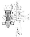
- a high bypass aircraft gas turbine engine 10 is connected to a fuel control 12 that includes a FADEC (full authority digital engine control) employing a microprocessor ( ⁇ ) 14 or signal processor. All the components of the signal processor, such as clocks, registers and input/output ports, have not been shown. Those components and their use with a signal processor are well known.
- a memory unit MEM 14.1 is shown, as the location for the program sequences employed by the fuel control 12 to regulate fuel to the engine.
- the fuel control primarily responds to power requests manifested by the position PLA produced from a power lever control 16 that contains a power lever 16.1.
- the fuel control 12 receives engine operating information over data lines 20, such as engine speed N2, temperature TEMP, compressor pressure PB and exhaust gas temperature EGT.
- the control 12 also controls displays 22, which indicate a non-recoverable surge and compressor blowout using the signal processing sequences described in this application, in particular concerning the flow chart shown in Fig. 2A-2B.
- the signal processor 14 operates at a very high computation rate, typically many millions of cycles per second, in the process executing many routines to control fuel flow and even other engine function. With the sequences show in Fig. 2A-2B, the routine is executed/run during these cycles following conventional programming. It will be obvious to a programmer, of course, that there may be ways to collect and process data following the sequences in Fig. 2A-2B other than the precise arrangement of the sequences shown.
- Step S3 involves computing a surge limit for PBDOT for N2C2, and the actual value for PB as read from the engine at step S4.
- a test is carried out at step S5 that determines if PB decreases at a rate exceeding the surge limit (computed in step S3).
- Step S6 sets a surge flag in memory if the test in step S5 produces an affirmative answer.
- step S7 the value of N2C2 is again read, a step also reached by a negative answer to the test made at step S6, but without setting the surge flag.
- step S8 a test is made of whether N2 is less than idle speed and N2DOT is less than a value, e.g., -25 RPM, meaning that N2 is decreasing faster than that rate. If the result at step S8, is positive, another flag, the N2 flag, is set in step S9. A negative answer at step S8, moves the process directly to step S10.
- step S10 another engine parameter or operating characteristic is read: either the temperature at location 49 (using conventional gas turbine location reference numbers) or the EGT, exhaust gas temperature, a signal on the line 20.1 in Fig. 1. This value is stored as T1, as it may be used in a subsequent test of EGT at a second interval.
- Step S9 moves to step S11, where a determination is made if the surge flag or the N2 flag has been set.
- a positive answer sets flag1 in step S12, from which the sequence goes to step S10.
- Step S13 produces a positive answer if flag 1 has been set, causing step S14 to hold the value of T1.
- an error value is produced manifesting the difference between T1 and latest value of T49, obtained during the next run through the routine, e.g., a few microseconds later. A longer delay may be incorporated.
- the purpose is to compare T49 twice if flag 1 has been set. If flagl has not been set, step S14 is bypassed, effectively meaning that the error will be zero.
- a positive answer means that T49 is greater than the redline temperature for the engine or the error is greater than some value, e.g., 50° C. If flag 1 has not been set, only the first part of the test will apply.
- Step S17 sets another flag, flag 2, if step S16 produces a positive answer.
- Step S18 is reached from step S17 and by a negative answer at step S16, and determines if N2 is below idle speed. If N2 is below idle, producing an affirmative answer in step 18, another flag, flag3, is set in step S19, from which the sequence moves to step S20, also reached by a negative answer at step S18.
- the value 1 means that flag 2 and flag 3 are set.
- Step S21 This causes an NRS (non-recoverable surge) signal to be produced over line 22.1 in step S21, activating the surge indicator in display 22.
- Step S22 removes the NRS signal when flag 3 is not set (value equals zero).
- Step S23 tests for a zero value for flag 2 (FLAG "not"), that is, the flag 2 is not present, N2DOT is less than -25 and flag 3 is set. The positive answer at step S23 causes a blowout signal to be sent to the display 22 for a preset time, e.g., 2 seconds. From step S24, the process moves to step S25, where a test is made for the absence or zero value of flag 3 (FLAG 3 "not") or the presence of the NRS signal.
- a positive answer to the test at step S25 resets the blowout timer used in step S24. Then the process ends, a terminus also reached by negative answers at steps S23 and step S25. This prevents a surge that takes place at just above idle speed from being declared a blowout initially and then a non-recoverable surge. Similarly, the blow out indication on display 22 is cleared when N2 is above idle or the surge flag is set.
Description
Claims (5)
- A gas turbine engine (10) comprising a fuel control (12) having signal processing means (14) responsive to signals indicating engine operating conditions including engine exhaust temperature (EGT) and engine compressor speed (N2), the signal processing means (14) comprising:means for providing a first signal indicating a surge condition;means for providing, in response to the first signal, a second signal indicating an exhaust temperature (EGT) elevated above an acceptable temperature;means for providing a third signal; andmeans for providing an indication of non-recoverable surge (SURGE) in response to the third signal, characterised in that the third signal is provided in response to both the second signal and a fourth signal indicating compressor speed (N2) less than idle.
- A gas turbine engine (10) as claimed in claim 1, further characterised in that the signal processing means (14) comprises:means for providing the first signal in response to a fifth signal indicating that compressor speed (N2) is less than idle and a sixth signal indicating that the derivative of compressor speed (N2) is less than a negative value;means for providing a seventh signal indicating the absence of the second signal;means for providing an eighth signal in response to the sixth signal and the seventh signal; andmeans for providing an indication of a blowout (BO) in response to the eighth signal.
- A gas turbine engine (10) as claimed in claim 2, further characterised in that the signal processing means (14) comprises means for providing the eighth signal only for a time interval that is reset when the first signal is provided and compressor speed (N2) is above idle.
- A gas turbine engine (10) as claimed in any preceding claim, further characterised in that the signal processing means (14) comprises means for providing the second signal in response to an exhaust temperature (EGT) higher than redline or a difference in exhaust temperature, at two successive times, that is greater than a stored value.
- A gas turbine (10) as claimed in any preceding claim, further characterised in that the signal processing means (14) comprises means for holding the third signal until compressor speed (N2) is above idle.
Applications Claiming Priority (3)
| Application Number | Priority Date | Filing Date | Title |
|---|---|---|---|
| US17234493A | 1993-12-23 | 1993-12-23 | |
| US172344 | 1993-12-23 | ||
| PCT/US1994/014104 WO1995017607A1 (en) | 1993-12-23 | 1994-12-08 | Non-recoverable surge and blowout detection in gas turbine engines |
Publications (2)
| Publication Number | Publication Date |
|---|---|
| EP0736142A1 EP0736142A1 (en) | 1996-10-09 |
| EP0736142B1 true EP0736142B1 (en) | 1998-07-22 |
Family
ID=22627317
Family Applications (1)
| Application Number | Title | Priority Date | Filing Date |
|---|---|---|---|
| EP95904847A Expired - Lifetime EP0736142B1 (en) | 1993-12-23 | 1994-12-08 | Non-recoverable surge and blowout detection in gas turbine engines |
Country Status (5)
| Country | Link |
|---|---|
| US (1) | US5752379A (en) |
| EP (1) | EP0736142B1 (en) |
| JP (1) | JP3299280B2 (en) |
| DE (1) | DE69411950T2 (en) |
| WO (1) | WO1995017607A1 (en) |
Families Citing this family (26)
| Publication number | Priority date | Publication date | Assignee | Title |
|---|---|---|---|---|
| US6164902A (en) * | 1998-12-11 | 2000-12-26 | United Technologies Corporation | Controlling stall margin in a gas turbine engine during acceleration |
| US6269627B1 (en) * | 1998-12-16 | 2001-08-07 | United Technologies Corporation | Rapid thrust response control logic for shaft-driven lift fan STOVL engine |
| US6270037B1 (en) * | 1998-12-16 | 2001-08-07 | United Technologies Corporation | Rapid response attitude control logic for shaft-driven lift fan STOVL engine |
| US6289274B1 (en) | 1999-08-13 | 2001-09-11 | United Technologies Corporation | Fuzzy logic based fuel flow selection system |
| US6513333B2 (en) * | 2000-05-25 | 2003-02-04 | Honda Giken Kogyo Kabushiki Kaisha | Surge detection system of gas turbine aeroengine |
| JP4705732B2 (en) * | 2000-05-25 | 2011-06-22 | 本田技研工業株式会社 | Surge detector for aircraft gas turbine engine |
| US6557400B2 (en) | 2001-03-30 | 2003-05-06 | Honeywell International Inc. | Surge bleed valve fault detection |
| EP1296045A3 (en) * | 2001-09-24 | 2004-07-14 | Goodrich Control Systems Limited | Electronic engine controller |
| EP1296046A3 (en) * | 2001-09-24 | 2004-07-14 | Goodrich Control Systems Limited | Electronic engine controller |
| GB0122956D0 (en) * | 2001-09-24 | 2001-11-14 | Lucas Industries Ltd | Fire resistant electronic engine controller |
| US7089746B2 (en) | 2002-06-26 | 2006-08-15 | Georgia Tech Reasearch Corporation | Systems and methods for detection of blowout precursors in combustors |
| US7454892B2 (en) * | 2002-10-30 | 2008-11-25 | Georgia Tech Research Corporation | Systems and methods for detection and control of blowout precursors in combustors using acoustical and optical sensing |
| US6871487B2 (en) * | 2003-02-14 | 2005-03-29 | Kulite Semiconductor Products, Inc. | System for detecting and compensating for aerodynamic instabilities in turbo-jet engines |
| US7975465B2 (en) * | 2003-10-27 | 2011-07-12 | United Technologies Corporation | Hybrid engine accessory power system |
| US7194382B2 (en) * | 2004-02-06 | 2007-03-20 | Georgia Tech Research Corporation | Systems and methods for detection of combustor stability margin |
| US7159401B1 (en) * | 2004-12-23 | 2007-01-09 | Kulite Semiconductor Products, Inc. | System for detecting and compensating for aerodynamic instabilities in turbo-jet engines |
| US8321119B2 (en) * | 2008-07-10 | 2012-11-27 | General Electric Company | Methods and systems to facilitate over-speed protection |
| US20100005657A1 (en) * | 2008-07-10 | 2010-01-14 | Van Vactor David R | Methods and systems to facilitate over-speed protection |
| US8224552B2 (en) * | 2008-07-10 | 2012-07-17 | General Electric Company | Methods and systems to facilitate over-speed protection |
| US10018122B2 (en) * | 2013-03-14 | 2018-07-10 | United Technologies Corporation | Pressure sensor noise filter prior to surge detection for a gas turbine engine |
| US20160195025A1 (en) * | 2013-08-27 | 2016-07-07 | United Technologies Corporation | Gas turbine flameout detection |
| FR3023323B1 (en) * | 2014-07-02 | 2016-07-01 | Snecma | METHOD FOR DETECTING FAILURE OF A VALVE IN A TURBOMOTEUR |
| CN104389804A (en) * | 2014-11-20 | 2015-03-04 | 哈尔滨广瀚燃气轮机有限公司 | Surge protection device |
| CN105673208B (en) * | 2016-01-11 | 2017-10-20 | 西北工业大学 | A kind of digital implementation of airspace engine fuel service system control sequential |
| US10371002B2 (en) * | 2016-06-14 | 2019-08-06 | General Electric Company | Control system for a gas turbine engine |
| US11629646B2 (en) | 2018-09-28 | 2023-04-18 | Raytheon Technologies Corporation | Differential geared amplification of auxiliary power unit |
Family Cites Families (15)
| Publication number | Priority date | Publication date | Assignee | Title |
|---|---|---|---|---|
| US3867717A (en) * | 1973-04-25 | 1975-02-18 | Gen Electric | Stall warning system for a gas turbine engine |
| US3852958A (en) * | 1973-09-28 | 1974-12-10 | Gen Electric | Stall protector system for a gas turbine engine |
| US4117668A (en) * | 1975-11-19 | 1978-10-03 | United Technologies Corporation | Stall detector for gas turbine engine |
| US4060980A (en) * | 1975-11-19 | 1977-12-06 | United Technologies Corporation | Stall detector for a gas turbine engine |
| US4137710A (en) * | 1977-01-26 | 1979-02-06 | United Technologies Corporation | Surge detector for gas turbine engines |
| US4118926A (en) * | 1977-02-28 | 1978-10-10 | United Technologies Corporation | Automatic stall recovery system |
| US4083235A (en) * | 1977-05-25 | 1978-04-11 | The United States Of America As Represented By The Secretary Of The Navy | Compressor stall warning system |
| US4581888A (en) * | 1983-12-27 | 1986-04-15 | United Technologies Corporation | Compressor rotating stall detection and warning system |
| US4594051A (en) * | 1984-05-14 | 1986-06-10 | Dresser Industries, Inc. | System, apparatus, and method for detecting and controlling surge in a turbo compressor |
| US4603546A (en) * | 1985-07-16 | 1986-08-05 | Rolls-Royce Limited | Control systems for gas turbine aeroengines |
| USRE34388E (en) * | 1989-04-13 | 1993-09-28 | General Electric Company | Method and apparatus for detecting stalls |
| US5012637A (en) * | 1989-04-13 | 1991-05-07 | General Electric Company | Method and apparatus for detecting stalls |
| US5051918A (en) * | 1989-09-15 | 1991-09-24 | United Technologies Corporation | Gas turbine stall/surge identification and recovery |
| US5269136A (en) * | 1992-03-30 | 1993-12-14 | United Technologies Corporation | Sub-idle stability enhancement and rotating stall recovery |
| US5375412A (en) * | 1993-04-26 | 1994-12-27 | United Technologies Corporation | Rotating stall recovery |
-
1994
- 1994-12-08 DE DE69411950T patent/DE69411950T2/en not_active Expired - Lifetime
- 1994-12-08 JP JP51745595A patent/JP3299280B2/en not_active Expired - Fee Related
- 1994-12-08 WO PCT/US1994/014104 patent/WO1995017607A1/en active IP Right Grant
- 1994-12-08 EP EP95904847A patent/EP0736142B1/en not_active Expired - Lifetime
-
1995
- 1995-07-26 US US08/506,758 patent/US5752379A/en not_active Expired - Lifetime
Also Published As
| Publication number | Publication date |
|---|---|
| DE69411950T2 (en) | 1999-03-25 |
| DE69411950D1 (en) | 1998-08-27 |
| WO1995017607A1 (en) | 1995-06-29 |
| JP3299280B2 (en) | 2002-07-08 |
| JPH09509713A (en) | 1997-09-30 |
| US5752379A (en) | 1998-05-19 |
| EP0736142A1 (en) | 1996-10-09 |
Similar Documents
| Publication | Publication Date | Title |
|---|---|---|
| EP0736142B1 (en) | Non-recoverable surge and blowout detection in gas turbine engines | |
| EP0418189B1 (en) | Gas turbine stall/surge identification and recovery | |
| JP3652729B2 (en) | Surge detector using engine signature | |
| EP0185601B1 (en) | Surge/stall cessation detection system | |
| US6059522A (en) | Compressor stall diagnostics and avoidance | |
| EP3287609B1 (en) | Turbofan shaft break detection system and method | |
| US5375412A (en) | Rotating stall recovery | |
| JPS6314167B2 (en) | ||
| EP0160078A1 (en) | Fault tolerant controller | |
| EP1069296B1 (en) | A method of obtaining an indication of the power output of a turbine | |
| US3677000A (en) | System for the detection and control of compressor stall | |
| US5012637A (en) | Method and apparatus for detecting stalls | |
| US4768338A (en) | Means for enhancing recovery of a surge condition in a gas turbine engine | |
| EP0268545B1 (en) | Method and means for enhancing recovery of a surge condition in a gas turbine engine | |
| USRE34388E (en) | Method and apparatus for detecting stalls | |
| EP0777828B1 (en) | Compressor stall avoidance | |
| EP0670425B1 (en) | Method of surge detection | |
| GB2122398A (en) | Engine stall early warning system | |
| EP1666732A2 (en) | Method of engine surge discrimination | |
| JPS6254138A (en) | Misfire discriminating device for engine | |
| EP3904659A1 (en) | Detecting condition of a shaft of a gas turbofan aircraft engine | |
| RU2054132C1 (en) | Method and device for protecting turbo-compressor against surging | |
| GB2128771A (en) | Fuel control system for a gas turbine engine | |
| EP0368793A2 (en) | Overspeed detection with hysteresis | |
| JPH0510175A (en) | Automatic storage method of engine critical output state |
Legal Events
| Date | Code | Title | Description |
|---|---|---|---|
| PUAI | Public reference made under article 153(3) epc to a published international application that has entered the european phase |
Free format text: ORIGINAL CODE: 0009012 |
|
| 17P | Request for examination filed |
Effective date: 19960723 |
|
| AK | Designated contracting states |
Kind code of ref document: A1 Designated state(s): DE FR GB |
|
| GRAG | Despatch of communication of intention to grant |
Free format text: ORIGINAL CODE: EPIDOS AGRA |
|
| 17Q | First examination report despatched |
Effective date: 19970915 |
|
| GRAG | Despatch of communication of intention to grant |
Free format text: ORIGINAL CODE: EPIDOS AGRA |
|
| GRAH | Despatch of communication of intention to grant a patent |
Free format text: ORIGINAL CODE: EPIDOS IGRA |
|
| GRAH | Despatch of communication of intention to grant a patent |
Free format text: ORIGINAL CODE: EPIDOS IGRA |
|
| GRAA | (expected) grant |
Free format text: ORIGINAL CODE: 0009210 |
|
| AK | Designated contracting states |
Kind code of ref document: B1 Designated state(s): DE FR GB |
|
| REF | Corresponds to: |
Ref document number: 69411950 Country of ref document: DE Date of ref document: 19980827 |
|
| ET | Fr: translation filed | ||
| PLBE | No opposition filed within time limit |
Free format text: ORIGINAL CODE: 0009261 |
|
| STAA | Information on the status of an ep patent application or granted ep patent |
Free format text: STATUS: NO OPPOSITION FILED WITHIN TIME LIMIT |
|
| 26N | No opposition filed | ||
| REG | Reference to a national code |
Ref country code: GB Ref legal event code: IF02 |
|
| PGFP | Annual fee paid to national office [announced via postgrant information from national office to epo] |
Ref country code: FR Payment date: 20081205 Year of fee payment: 15 |
|
| REG | Reference to a national code |
Ref country code: FR Ref legal event code: ST Effective date: 20100831 |
|
| PG25 | Lapsed in a contracting state [announced via postgrant information from national office to epo] |
Ref country code: FR Free format text: LAPSE BECAUSE OF NON-PAYMENT OF DUE FEES Effective date: 20091231 |
|
| PGFP | Annual fee paid to national office [announced via postgrant information from national office to epo] |
Ref country code: GB Payment date: 20131204 Year of fee payment: 20 Ref country code: DE Payment date: 20131204 Year of fee payment: 20 |
|
| REG | Reference to a national code |
Ref country code: DE Ref legal event code: R071 Ref document number: 69411950 Country of ref document: DE |
|
| REG | Reference to a national code |
Ref country code: DE Ref legal event code: R071 Ref document number: 69411950 Country of ref document: DE |
|
| REG | Reference to a national code |
Ref country code: GB Ref legal event code: PE20 Expiry date: 20141207 |
|
| PG25 | Lapsed in a contracting state [announced via postgrant information from national office to epo] |
Ref country code: GB Free format text: LAPSE BECAUSE OF EXPIRATION OF PROTECTION Effective date: 20141207 |