EP0736846A2 - Microprocessor systems for electronic postage arrangements - Google Patents
Microprocessor systems for electronic postage arrangements Download PDFInfo
- Publication number
- EP0736846A2 EP0736846A2 EP96110413A EP96110413A EP0736846A2 EP 0736846 A2 EP0736846 A2 EP 0736846A2 EP 96110413 A EP96110413 A EP 96110413A EP 96110413 A EP96110413 A EP 96110413A EP 0736846 A2 EP0736846 A2 EP 0736846A2
- Authority
- EP
- European Patent Office
- Prior art keywords
- microprocessor
- data
- memories
- accounting
- random access
- Prior art date
- Legal status (The legal status is an assumption and is not a legal conclusion. Google has not performed a legal analysis and makes no representation as to the accuracy of the status listed.)
- Granted
Links
Images


Classifications
-
- G—PHYSICS
- G07—CHECKING-DEVICES
- G07B—TICKET-ISSUING APPARATUS; FARE-REGISTERING APPARATUS; FRANKING APPARATUS
- G07B17/00—Franking apparatus
- G07B17/00185—Details internally of apparatus in a franking system, e.g. franking machine at customer or apparatus at post office
- G07B17/00362—Calculation or computing within apparatus, e.g. calculation of postage value
- G07B2017/00395—Memory organization
- G07B2017/00411—Redundant storage, e.g. back-up of registers
Definitions
- This invention relates to microprocessor systems and is applicable to electronic postage arrangements having electronic accounting units.
- An electronic postage meter having an acounting unit with a microprocessor, and nonvolatile memory for storing accounting data is disclosed, for example, in US Patent Application Serial No.089,413 (US Patent No. 4,301,507).
- the accounting data is stored in the random access memory and retrieved from the random access memory by way of common address and data lines of the microcomputer system. While in most instances it can be ensured that the accounting data stored in the memory will be correct, there are certain conditions that can occur that can result in non-detectable errors in the data.
- the microprocessor program for the postal meter thus includes a subroutine for comparing the data stored in the redundant memories, to provide an error indication if the stored data in the two memories is different. While this technique increases the reliability of the stored data, there are certain conditions in which even this type of a redundant system will not enable the determination of an error. Furthermore, the known system tests during printing for various indications of malfunction of the print value setting and printing mechanisms. Other types of malfunction are also detected. Upon detection of a malfunction, an appropriate failure code is written into memory and the meter is disabled. It must, of course, be emphasized that, in a postage meter, it is essential that the highest degree of reliability of the accounting data be obtained.
- An object of the present invention is to provide a microprocessor system for an electronic postage meter wherein the possibility of error conditions that are not detectable is reduced.
- a microprocessor system for an electronic postage arrangement comprising: a microprocessor; register means coupled to said microprocessor for storing postage accounting data; a plurality of sensors for detecting operation conditions in said postage meter; and said microprocessor having a software routine stored in a permanent memory to check said sensors periodically during operation; characterised by means responsive to the noncorrespondence of the outputs of said sensors and a unique code stored in said microprocessor permanent memory, upon a comparison performed in accordance with said software routine, for indicating an error condition.
- a microprocessor system for an electronic postage meter and characterised by: a microprocessor with a plurality of address lines and a plurality of data lines, and control line means, and random access memory means connected to said address and data lines and control line means to enable transfer of data between said random access memory means and microprocessor; a printer connected to be controlled by said microprocessor; and feedback means for signalling the setting of the printer means to the microprocessor, wherein said random access memory comprises first and second random access memories; and means independently responsive to feedback from said feedback means to update the accounting data in each of said first and second random access memories.
- a microprocessor system for an electronic postage meter characterised by: a printing means; first and second microprocessors; first and second accounting memories connected to be separately controlled by said first and second microprocessors, said first and second microprocessors having program routines for separately updating their respective accounting memories to account for the printing of postage by said printing means; and means for comparing the accounting results in said first and second accounting memories for disabling said postage meter in the absence of a coincidence of data in said first and second accounting memories.
- a microprocessor system characterised by an address bus having a plurality of address lines; a data bus having a plurality of data lines; a control bus having a plurality of control lines; a micorprocessor connected to each of the address lines of data lines of said address and data bus, and coupled to said control bus; and first and second random access memories each connected to different lines of said address bus and different lines of said data bus, whereby said random access memories may be separately addressed.
- a microprocessor system forming an electronic accounting system, such as may be employed in an electronic postage meter.
- the system incorporates a central processing unit 10, such as a microprocessor, and a read only memory 11 storing programs for operation of the system.
- the central processing unit 10 is coupled to one or more peripherals, such as, for example, the printing unit 12 and control unit 13 of an electronic postage meter such as disclosed in copending U.S. Patent Application Serial No. 089,413 (Patent No. 4,301,507).
- a secure housing 14 surrounds various components of the system, such as the central processing unit 10 and printing unit 12.
- the ports are in the form of a pair of one-way transmission paths with opto couplers 15 and 16 at the secure housing, in order to inhibit the application of any electric potentials to the accounting unit without showing evidence of attempts to damage the unit.
- the opto couplers preferably provide for two-way serial intercommunication between the units on a bit-by-bit basis, in order to minimize the number of ports necessary in the housing.
- the printing unit, as well as the control unit may, if desired, have separate microprocessors incorporated therein, enabling the use of a plurality of dedicated microprocessor systems. This not only enhances the security of the system, but also increases its reliability by restricting the required tasks of each microprocessor to a specific portion of the overall operation of the system. For example, the possibility of conflicting program requirement is thereby greatly reduced.
- a pair of random access memories 20, 21 is also provided within the secure housing.
- the random access memories 20 and 21 are preferably non-volatile memories of conventional nature, so that accounting data may be stored therein without loss even though external power to the system may be lost.
- the random access memories may be of the type employing battery back-up, Earom or EEPROM.
- the random access memory 20 is connected to the central processing unit 10 by way of a plurality of address lines 22 and a plurality of data lines 23.
- the random access memory is coupled to the central processing unit 10 by way of another plurality of address lines 24, and another plurality of data lines 25. It is necessary that both the address lines and the data lines coupled to the random access memories be different.
- address lines A0 - A7 are of a conventional microprocessor system and may be coupled to the random access memory 20, while address lines C0 - C7 are coupled to the random access memory 21.
- conventional data lines B0 - B3 may be coupled to the random access memory 20, with data lines D4 - D7 being coupled to the random access memory 21.
- redundancy In an accounting system that requires both security and reliability, it is desirable to provide redundancy. A certain degree of redundancy may be obtained if the random access memories are connected to the central processing unit by separate data lines, although employing the same address lines. In such a system, the same data may be stored or retrieved from the two random access memories by way of their respective separate data lines, either simultaneously or at different times under control of the respective chip enable signals. While in many instances such an arrangement will enable the detection of errors, upon comparison of data in the two memories, there are in fact possibilities of error that cannot be detected.
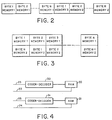
- the two random access memories may be simultaneously addressed, employing their separate address lines, for the storage or recovery of the same information, this may also result in errors that could not be detectable or correctable. For example, it is possible that a transient on the bus lines could interfere, in the same manner, with the simultaneously transmitted data. Accordingly, as illustrated in Figure 2, the two memories are addressed, with respect to the same data, in a sequential manner. For example, all of the sequential bytes of a message may be first applied to, or received from, the first memory, i.e. memory 1. Following the transfer of this message, with respect to the first memory, the same message is then transmitted with respect to the second memory. It will, of course, be apparent that the term "byte" herein refers to data of a length equal to the number of data lines connected to each memory.
- each memory may be updated or read simultaneously but with different data being transmitted to or from each memory at any instant, as illustrated in Figure 3.
- Figures 2 and 3 hence illustrate two techniques for minimizing the occurrence of undetectable errors resulting from the occurrence, for example, of transient pulses. It is apparent that it would be unlikely for the same interference to occur with sequentially transmitted data.
- the data may be stored in the two memories in a different form.
- the data stored in one or both of the memories may be coded, in order further to minimize the occurrence of errors undetectable by comparison of the data stored in the two memories.
- a coder/decoder 30 may be employed to code and decode the data stored in the random access memory 20, applied to and received from the data bus 23.
- a coder/decoder 31 may optionally be provided for coding and decoding data in the random access memory 21. If such an additional coder/decoder is employed, it is preferable that it have a different coding than that of the coder/decoder 30.
- the programs of the microprocessor have appropriate subroutines to determine, if a comparison between the data shows an inconsistency, which memory bears the greater likelihood of correctness.
- further routines may he provided in the event of an inability of the system to determine which of the data entries are error free, to provide an error indication that inhibits further operation of the system.
- each memory unit may be made independently responsive to determined conditions.
- the two memories may be independently responsive to each feedback of a printer setting, in order to update the separate memories, with an overriding subroutine being provided for cross-checking, i.e., comparing the data stored in the two memories.
- the independent control may be, for example, in the form of a memory controller.
- electronic postage meters are provided with a plurality of sensors, such as the sensors 50, 51 and 52 illustrated coupled to the central processing unit 10 in Figure 1. These sensors may be employed for checking a number of conditions within the meter, such as the position of a shutter bar blocking operation of the meter, the positions of various interposers controlling operation of the postage meter, and various other condition sensors such as temperature and humidity.
- sensors such as the sensors 50, 51 and 52 illustrated coupled to the central processing unit 10 in Figure 1.
- These sensors may be employed for checking a number of conditions within the meter, such as the position of a shutter bar blocking operation of the meter, the positions of various interposers controlling operation of the postage meter, and various other condition sensors such as temperature and humidity.
- non-electronic postage meters of the type employing microprocessors for control such as disclosed in U.S. Patent 3,978,457, certain of these sensors are interrogated by a software routine upon the initial application of power to the meter.
- the positions of the various shutter bars and interposers are also determined by software routines initiated by various externally originating conditions, such as, for example, manually controlled operations for initiating the printing of postage.
- the error checking routines for checking such sensors, as well as for checking additional conditions such as the correctness of data stored in the memories are hence invoked only when specifically requested in response to external stimuli. Thus, even though a condition may have occurred, between operations of the postage meter, that would eventually cause it to cease operation (i.e. upon the next call for printing of postage), the meter may still deceptively appear externally to be operable.
- a program for the microprocessor effects the checking of the registers of the random access memory, as well as the various sensors, which may be optical switches, and all other critical data indicators at regular times during the course of operation of the postage meter, rather than simply checking these parameters at startup of the meter and uncalled for by external stimuli.
- the main routine of the postage meter to which it always returns following the completion of, for example, a postage printing operation, includes software subroutines that periodically check critical parameters, such as the proper positioning of mechanical elements in the meter and the correct comparison of data in memories, as well as the correctness of the data in accordance with control sum data. This technique enables the additional advantageous periodic checking of further sensors mounted, for example, to detect mechanical violation of the security of the housing.
- the sensors 50, 51 and 52 may be connected to set a plurality of stages of a shift register 55. It will, of course, be understood that the number of such sensors may be greater than the three illustrated.
- the shift register 55 is coupled to the address and read out by the central processing unit 10 at determined times in the main program. A coded bit pattern is provided in the read only memory 11, corresponding to the correct error-free conditions of the sensors. At the times during the program when the sensors are to be tested, the shift register, under control of the central processing unit, shifts out the existing bit pattern for comparison with the stored bit pattern in the read only memory 11.
- the status of the various sensors in the meter may be continually determined, so that the meter may be disabled as soon as a condition exists that threatens the integrity of the meter.
- the shift register may be, of course, shifted under the control of the microprocessor, by the conventional clock source of the system.
- the shift register may be preprogrammed, in accordance with a determined unique pattern, so that the output of the shift register may be compared with a predetermined "good" condition.
- the information available from an eight or sixteen bit pattern code, in accordance with this embodiment of the invention, may thus provide a very large degree of sophistication for the determination of any appropriate error checking for diagnostic purposes, using signature analysis techniques. This form of error checking may be imposed upon various system constraints for both diagnostic and possible error correction on an automatic basis.
- the printing unit 12 and control unit 13 may include dedicated microprocessors for controlling the specific functions of these units, thereby enabling the use of a dedicated system for the accounting unit including the central processing unit 10, read only memory 11 and random access memories 20 and 21.
- the printing unit 12 may further incorporate a random access memory 60, and/or the control unit 13 may include a nonvolatile random access memory 61.
- the nonvolatile random access memories 20, 21 of the accounting system are intercoupled with separate microprocessors 60 and 61, each of the microprocessors having a separate read only memory 62, 63 respectively, for storing the operating programs for the respective microprocessor.
- the read only memory as well as other components of the system, may be incorporated in the same integrated circuit as the microprocessor. Since the two microprocessors are separately controlled, and have separate address and data lines 64, 65 respectively, the two random access memories are thereby entirely independently controlled.
- the two microprocessors separately communicate with the control unit 13 and printer 82 by way of separate selector switches 70 and 71 addressed by the respective microprocessors 60 and 61.
- each of the microprocessors may receive signals from the printer and control unit, and each of them may also transmit messages.
- data processed in the two microprocessors may be compared by means of a data latch 72 controllable by either of the microprocessors.
- input data received for example, from the keyboard 73 or other peripheral device coupled to the control unit 13, is applied by way of the opto couplers 15 and 16 and the selecting switches 70 and 71 to the two microprocessor systems.
- the data may be input to the two microprocessors in response to an interrupt signal.
- the two microprocessors in response to the input information, perform the necessary accounting procedures independently of one another, with respect to the data stored in the respective random access memories.
- the programs of the two microprocessors enable interchange of accounting data for comparison, for example, on a contention basis, by way of the data latch 72.
- the programs of the two microprocessors may enable, for example, only one of the microprocessors to control the display 75 coupled to the control unit 13, and/or to control the printer 82.
- redundant control may be employed, whereby the control of a printer function, or the control of a display, may require the common occurrence of the output function from the two microprocessors.
- This may be effected, for example, in the manner disclosed in U.S. Patent Application Serial No. 089,413 filed October 30, 1979, and assigned to the assignee of the present application, by controlling a pair of series transistors separately by the two microprocessors, whereby the common output of the series transistors effects the desired control. It is, of course, apparent that other techniques may be employed for this purpose.
- the printer unit is more completely shown as comprised of a microprocessor 80 coupled to the opto couplers 17 and 18, and controlling a print setter 81.
- the print setter 81 sets the printwheels in a printer 82, the setting of the printwheels being fed back to the microprocessor 80 by way of a feedback path 83.
- This feedback enables the printer unit to determine if an error has occurred in the setting of the printwheels, and thereby to disable the meter in the event of an erroneous setting.
- the feedback setting may be applied from the microprocessor 80 to the opto couplers 17 and 18, thereby enabling the two microprocessors in the accounting system to be separately responsive to the feedback signals, for accounting for postage to be printed.
- the function of disabling the meter in the illustrated embodiments, may be effected by inhibiting, under program control, operation of the mechanical elements of the meter.
- the existence of an error requiring disabling of the meter may direct the routines of the microprocessor to perform an endless loop. Errors that do not require disabling of the meter may be displayed, under control of the microprocessor, by means of the display 73 coupled to the external control unit.
- redundant nonvolatile memories are provided in the accounting unit of an electronic postage meter, the accounting unit having a microprocessor controlled to store accounting data redundantly in the two memories.
- the two redundant memories are interconnected with the microprocessor, i.e. the microcomputer bus, by way of entirely separate groups of data and address lines.
- various error conditions such as the shorting of a pair of address lines, will not result in the erroneous addressing of both of the memories. Accordingly, under such conditions, the shorting of a pair of address lines will not result in the storage of the same data in both of the memories, so that a comparison of stored data will result in the detection of the error condition.
- corresponding data is applied redundantly to the redundant memories at different times. This may be effected by separately applying the data sequentially to the two memories. Alternatively, data may be simultaneously applied to or retrieved from the two memories, with the data transferred at any instant with respect to the two memories corresponding to different information. As a result, instantaneously occurring transients on the transmission lines will not be likely to affect the corresponding data stored in the two memories in the same fashion. This system thereby minimizes the possibility of nondetectable and/or noncorrectable errors resulting from transients.
- the redundancy of the accounting system may be increased by also employing redundant microprocessors for controlling the two memories.
- the program of the microprocessor may be directed to the periodic testing of various critical parameters within the microprocessor, as part of a main routine, the testing routine only being interrupted, if necessary, during a conventional postage printing operation such as the printing of postage and accounting therefor.
- the routine of the postage meter enables the continuous testing of such parameters, so that the postage meter may be disabled as soon as a condition exists that threatens the integrity of the accounting data.
- the error checking on a periodic basis may test not only the physical parameters, such as positions of various mechanical elements, but also may effect the comparison of the data stored in the two memories, as well as performing control sum checks to determine if the data stored in each memory is in accordance with determined relationships.
- Other types of memory can, of course, be employed instead of RAM such as serial memory.
Abstract
Description
- This invention relates to microprocessor systems and is applicable to electronic postage arrangements having electronic accounting units.
- An electronic postage meter having an acounting unit with a microprocessor, and nonvolatile memory for storing accounting data, is disclosed, for example, in US Patent Application Serial No.089,413 (US Patent No. 4,301,507). In this system the accounting data is stored in the random access memory and retrieved from the random access memory by way of common address and data lines of the microcomputer system. While in most instances it can be ensured that the accounting data stored in the memory will be correct, there are certain conditions that can occur that can result in non-detectable errors in the data.
- In order to overcome such problems, it has been proposed to employ redundant memories (EP-A-19515). The microprocessor program for the postal meter thus includes a subroutine for comparing the data stored in the redundant memories, to provide an error indication if the stored data in the two memories is different. While this technique increases the reliability of the stored data, there are certain conditions in which even this type of a redundant system will not enable the determination of an error. Furthermore, the known system tests during printing for various indications of malfunction of the print value setting and printing mechanisms. Other types of malfunction are also detected. Upon detection of a malfunction, an appropriate failure code is written into memory and the meter is disabled. It must, of course, be emphasized that, in a postage meter, it is essential that the highest degree of reliability of the accounting data be obtained.
- An object of the present invention is to provide a microprocessor system for an electronic postage meter wherein the possibility of error conditions that are not detectable is reduced.
- According to one aspect of the invention, there is provided a microprocessor system for an electronic postage arrangement comprising: a microprocessor; register means coupled to said microprocessor for storing postage accounting data; a plurality of sensors for detecting operation conditions in said postage meter; and said microprocessor having a software routine stored in a permanent memory to check said sensors periodically during operation; characterised by means responsive to the noncorrespondence of the outputs of said sensors and a unique code stored in said microprocessor permanent memory, upon a comparison performed in accordance with said software routine, for indicating an error condition.
- According to another aspect of the invention, there is provided a microprocessor system for an electronic postage meter and characterised by: a microprocessor with a plurality of address lines and a plurality of data lines, and control line means, and random access memory means connected to said address and data lines and control line means to enable transfer of data between said random access memory means and microprocessor; a printer connected to be controlled by said microprocessor; and feedback means for signalling the setting of the printer means to the microprocessor, wherein said random access memory comprises first and second random access memories; and means independently responsive to feedback from said feedback means to update the accounting data in each of said first and second random access memories.
- According to a further aspect of the invention, there is provided a microprocessor system for an electronic postage meter characterised by: a printing means; first and second microprocessors; first and second accounting memories connected to be separately controlled by said first and second microprocessors, said first and second microprocessors having program routines for separately updating their respective accounting memories to account for the printing of postage by said printing means; and means for comparing the accounting results in said first and second accounting memories for disabling said postage meter in the absence of a coincidence of data in said first and second accounting memories.
- According to yet another aspect of the invention, there is provided a microprocessor system characterised by an address bus having a plurality of address lines; a data bus having a plurality of data lines; a control bus having a plurality of control lines; a micorprocessor connected to each of the address lines of data lines of said address and data bus, and coupled to said control bus; and first and second random access memories each connected to different lines of said address bus and different lines of said data bus, whereby said random access memories may be separately addressed.
- In order that the invention will be more clearly understood, it will now be disclosed in greater detail by way of example with reference to the accompanying drawings, in which:
- Figure 1
- is a block diagram of one embodiment of a microprocessor system for an electronic postage meter in accordance with the invention;
- Figure 2
- is a time diagram illustrating the sequence of addressing the redundant memories in accordance with another embodiment of the invention;
- Figure 3
- is a time diagram illustrating another sequence for addressing the redundant memories in accordance with an embodiment of the invention;
- Figure 4
- is a block diagram of a portion of a modification of the system of Figure 1;
- Figure 5
- is a block diagram of a further modification of a portion of the system of Figure 1; and
- Figure 6
- is a block diagram of a further embodiment of the invention.
- Referring now to the drawings, and more in particular to Figure 1, therein is illustrated a microprocessor system forming an electronic accounting system, such as may be employed in an electronic postage meter. The system incorporates a
central processing unit 10, such as a microprocessor, and a read onlymemory 11 storing programs for operation of the system. Thecentral processing unit 10 is coupled to one or more peripherals, such as, for example, theprinting unit 12 andcontrol unit 13 of an electronic postage meter such as disclosed in copending U.S. Patent Application Serial No. 089,413 (Patent No. 4,301,507). In the system of figure 1 asecure housing 14 surrounds various components of the system, such as thecentral processing unit 10 andprinting unit 12. As a consequence, it is necessary to provide ports between the central processing unit andexternal control unit 13, in order to enable two-way communication between these units. Preferably, the ports are in the form of a pair of one-way transmission paths withopto couplers - In addition, it is desirable, as discussed in U.S. Application Serial No. 089,413 (Patent No. 4,301,507) to enable intercommunication between the printing unit and
central processing unit 10 by way of a similar pair ofopto coupling devices - The printing unit, as well as the control unit may, if desired, have separate microprocessors incorporated therein, enabling the use of a plurality of dedicated microprocessor systems. This not only enhances the security of the system, but also increases its reliability by restricting the required tasks of each microprocessor to a specific portion of the overall operation of the system. For example, the possibility of conflicting program requirement is thereby greatly reduced.
- As illustrated in Figure 1, a pair of
random access memories random access memories - The
random access memory 20 is connected to thecentral processing unit 10 by way of a plurality ofaddress lines 22 and a plurality ofdata lines 23. The random access memory is coupled to thecentral processing unit 10 by way of another plurality ofaddress lines 24, and another plurality ofdata lines 25. It is necessary that both the address lines and the data lines coupled to the random access memories be different. For example, address lines A0 - A7 are of a conventional microprocessor system and may be coupled to therandom access memory 20, while address lines C0 - C7 are coupled to therandom access memory 21. Similarly, conventional data lines B0 - B3 may be coupled to therandom access memory 20, with data lines D4 - D7 being coupled to therandom access memory 21. - In an accounting system that requires both security and reliability, it is desirable to provide redundancy. A certain degree of redundancy may be obtained if the random access memories are connected to the central processing unit by separate data lines, although employing the same address lines. In such a system, the same data may be stored or retrieved from the two random access memories by way of their respective separate data lines, either simultaneously or at different times under control of the respective chip enable signals. While in many instances such an arrangement will enable the detection of errors, upon comparison of data in the two memories, there are in fact possibilities of error that cannot be detected. For example, if two of the address lines are inadvertently shorted together, either in the microprocessor itself or externally thereof, the same erroneous data will be stored in the two random access memories, so that comparison of the data stored in the two memories will not reveal an error condition.
- This problem is overcome by employing an entirely different set of address lines of the address bus for addressing the two random access memories. Preferably, of course, the number of address lines, and the number of data lines, connected to each of the random access memories is the same. If, now, two address lines of the system are shorted together, for example, there is little likelihood that tile resultant data stored in the two memories will be the same, so that the reliability of the system, in detection of errors, is greatly increased.
- While the two random access memories may be simultaneously addressed, employing their separate address lines, for the storage or recovery of the same information, this may also result in errors that could not be detectable or correctable. For example, it is possible that a transient on the bus lines could interfere, in the same manner, with the simultaneously transmitted data. Accordingly, as illustrated in Figure 2, the two memories are addressed, with respect to the same data, in a sequential manner. For example, all of the sequential bytes of a message may be first applied to, or received from, the first memory, i.e.
memory 1. Following the transfer of this message, with respect to the first memory, the same message is then transmitted with respect to the second memory. It will, of course, be apparent that the term "byte" herein refers to data of a length equal to the number of data lines connected to each memory. - In order to reduce the time necessary for updating or reading the memory, each memory may be updated or read simultaneously but with different data being transmitted to or from each memory at any instant, as illustrated in Figure 3.
- Figures 2 and 3 hence illustrate two techniques for minimizing the occurrence of undetectable errors resulting from the occurrence, for example, of transient pulses. It is apparent that it would be unlikely for the same interference to occur with sequentially transmitted data.
- In a still further embodiment of the invention, the data may be stored in the two memories in a different form. For example, the data stored in one or both of the memories may be coded, in order further to minimize the occurrence of errors undetectable by comparison of the data stored in the two memories. For example, as illustrated in Figure 4, a coder/
decoder 30 may be employed to code and decode the data stored in therandom access memory 20, applied to and received from thedata bus 23. A coder/decoder 31 may optionally be provided for coding and decoding data in therandom access memory 21. If such an additional coder/decoder is employed, it is preferable that it have a different coding than that of the coder/decoder 30. - It will, of course, be understood that the programs of the microprocessor have appropriate subroutines to determine, if a comparison between the data shows an inconsistency, which memory bears the greater likelihood of correctness. In addition, further routines may he provided in the event of an inability of the system to determine which of the data entries are error free, to provide an error indication that inhibits further operation of the system.
- In the embodiment of the invention illustrated in Figures 2 and 3, the two memories are addressed under the control of a fixed program responsive, for example, to a determined condition in the system. As a consequence, a determined relationship necessarily exists between the addressing times for the two memories. As a further modification, when separate memory units are provided, each memory unit may be made independently responsive to determined conditions. For example, when the accounting system is interconnected as illustrated in Figure 1 to form a postage meter, the two memories may be independently responsive to each feedback of a printer setting, in order to update the separate memories, with an overriding subroutine being provided for cross-checking, i.e., comparing the data stored in the two memories. The independent control may be, for example, in the form of a memory controller. By thus making the two memory units operable more independently from one another, the chances of a greater error-free operation are substantially enhanced.
- In order to ensure proper operation, and thereby to maintain the integrity of the accounting information stored therein, electronic postage meters are provided with a plurality of sensors, such as the
sensors central processing unit 10 in Figure 1. These sensors may be employed for checking a number of conditions within the meter, such as the position of a shutter bar blocking operation of the meter, the positions of various interposers controlling operation of the postage meter, and various other condition sensors such as temperature and humidity. In non-electronic postage meters of the type employing microprocessors for control, such as disclosed in U.S. Patent 3,978,457, certain of these sensors are interrogated by a software routine upon the initial application of power to the meter. The positions of the various shutter bars and interposers, for example, are also determined by software routines initiated by various externally originating conditions, such as, for example, manually controlled operations for initiating the printing of postage. The error checking routines for checking such sensors, as well as for checking additional conditions such as the correctness of data stored in the memories, are hence invoked only when specifically requested in response to external stimuli. Thus, even though a condition may have occurred, between operations of the postage meter, that would eventually cause it to cease operation (i.e. upon the next call for printing of postage), the meter may still deceptively appear externally to be operable. - In accordance with a further feature of the invention, a program for the microprocessor effects the checking of the registers of the random access memory, as well as the various sensors, which may be optical switches, and all other critical data indicators at regular times during the course of operation of the postage meter, rather than simply checking these parameters at startup of the meter and uncalled for by external stimuli. By thus providing periodic checks, the possibility of error-free operation is even more greatly enhanced. In other words, the main routine of the postage meter, to which it always returns following the completion of, for example, a postage printing operation, includes software subroutines that periodically check critical parameters, such as the proper positioning of mechanical elements in the meter and the correct comparison of data in memories, as well as the correctness of the data in accordance with control sum data. This technique enables the additional advantageous periodic checking of further sensors mounted, for example, to detect mechanical violation of the security of the housing.
- For this purpose, as illustrated in Figure 5, the
sensors shift register 55. It will, of course, be understood that the number of such sensors may be greater than the three illustrated. Theshift register 55 is coupled to the address and read out by thecentral processing unit 10 at determined times in the main program. A coded bit pattern is provided in the read onlymemory 11, corresponding to the correct error-free conditions of the sensors. At the times during the program when the sensors are to be tested, the shift register, under control of the central processing unit, shifts out the existing bit pattern for comparison with the stored bit pattern in the read onlymemory 11. Thus, the status of the various sensors in the meter may be continually determined, so that the meter may be disabled as soon as a condition exists that threatens the integrity of the meter. - The shift register may be, of course, shifted under the control of the microprocessor, by the conventional clock source of the system. Alternatively, the shift register may be preprogrammed, in accordance with a determined unique pattern, so that the output of the shift register may be compared with a predetermined "good" condition. The information available from an eight or sixteen bit pattern code, in accordance with this embodiment of the invention, may thus provide a very large degree of sophistication for the determination of any appropriate error checking for diagnostic purposes, using signature analysis techniques. This form of error checking may be imposed upon various system constraints for both diagnostic and possible error correction on an automatic basis.
- In the system illustrated in Figure 1, as discussed above, the
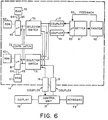
printing unit 12 andcontrol unit 13 may include dedicated microprocessors for controlling the specific functions of these units, thereby enabling the use of a dedicated system for the accounting unit including thecentral processing unit 10, read onlymemory 11 andrandom access memories printing unit 12 may further incorporate arandom access memory 60, and/or thecontrol unit 13 may include a nonvolatilerandom access memory 61. - In a further embodiment of the invention, as illustrated in Figure 6, the nonvolatile
random access memories separate microprocessors memory data lines control unit 13 andprinter 82 by way of separate selector switches 70 and 71 addressed by therespective microprocessors data latch 72 controllable by either of the microprocessors. - In the arrangement of Figure 6, input data received, for example, from the
keyboard 73 or other peripheral device coupled to thecontrol unit 13, is applied by way of theopto couplers switches display 75 coupled to thecontrol unit 13, and/or to control theprinter 82. Alternatively, of course, redundant control may be employed, whereby the control of a printer function, or the control of a display, may require the common occurrence of the output function from the two microprocessors. This may be effected, for example, in the manner disclosed in U.S. Patent Application Serial No. 089,413 filed October 30, 1979, and assigned to the assignee of the present application, by controlling a pair of series transistors separately by the two microprocessors, whereby the common output of the series transistors effects the desired control. It is, of course, apparent that other techniques may be employed for this purpose. - The arrangement of Figure 6 thereby increases the redundancy of the system, so that even a failure in a microprocessor will enable the determination, with great reliability, the occurrence of an error condition that may require the disabling of the meter.
- In the system of Figure 6, the printer unit is more completely shown as comprised of a
microprocessor 80 coupled to theopto couplers print setter 81. Theprint setter 81 sets the printwheels in aprinter 82, the setting of the printwheels being fed back to themicroprocessor 80 by way of afeedback path 83. This feedback enables the printer unit to determine if an error has occurred in the setting of the printwheels, and thereby to disable the meter in the event of an erroneous setting. The feedback setting may be applied from themicroprocessor 80 to theopto couplers - It is, of course, apparent that suitable control lines are provided connected to the microprocessor and random access memories in the conventional manner, for controlling the systems.
- The function of disabling the meter, in the illustrated embodiments, may be effected by inhibiting, under program control, operation of the mechanical elements of the meter. Alternatively, the existence of an error requiring disabling of the meter may direct the routines of the microprocessor to perform an endless loop. Errors that do not require disabling of the meter may be displayed, under control of the microprocessor, by means of the
display 73 coupled to the external control unit. - Thus, in accordance with one aspect of the invention, redundant nonvolatile memories are provided in the accounting unit of an electronic postage meter, the accounting unit having a microprocessor controlled to store accounting data redundantly in the two memories. In order to minimize the possibility of nondetectable errors, the two redundant memories are interconnected with the microprocessor, i.e. the microcomputer bus, by way of entirely separate groups of data and address lines. As a result of the complete separation of the addressing and data, various error conditions, such as the shorting of a pair of address lines, will not result in the erroneous addressing of both of the memories. Accordingly, under such conditions, the shorting of a pair of address lines will not result in the storage of the same data in both of the memories, so that a comparison of stored data will result in the detection of the error condition.
- In accordance with a further embodiment of the invention, corresponding data is applied redundantly to the redundant memories at different times. This may be effected by separately applying the data sequentially to the two memories. Alternatively, data may be simultaneously applied to or retrieved from the two memories, with the data transferred at any instant with respect to the two memories corresponding to different information. As a result, instantaneously occurring transients on the transmission lines will not be likely to affect the corresponding data stored in the two memories in the same fashion. This system thereby minimizes the possibility of nondetectable and/or noncorrectable errors resulting from transients.
- In accordance with a still further embodiment of the invention, the redundancy of the accounting system may be increased by also employing redundant microprocessors for controlling the two memories.
- In order to still further minimize the possibility of printing postage without accounting, the program of the microprocessor may be directed to the periodic testing of various critical parameters within the microprocessor, as part of a main routine, the testing routine only being interrupted, if necessary, during a conventional postage printing operation such as the printing of postage and accounting therefor. As a consequence, the routine of the postage meter enables the continuous testing of such parameters, so that the postage meter may be disabled as soon as a condition exists that threatens the integrity of the accounting data. The error checking on a periodic basis may test not only the physical parameters, such as positions of various mechanical elements, but also may effect the comparison of the data stored in the two memories, as well as performing control sum checks to determine if the data stored in each memory is in accordance with determined relationships. Other types of memory can, of course, be employed instead of RAM such as serial memory.
- While the invention has been disclosed and described with reference to a limited number of embodiments, it will be apparent that variations and modifications may be made therein, and it is intended in the following claims to cover each such variation and modification as falls within the true scope of the invention.
Claims (12)
- A microprocessor system for an electronic postage arrangement comprising: a microprocessor (10); register means (20, 21) coupled to said microprocessor for storing postage accounting data; a plurality of sensors (50, 51, 52) for detecting operation conditions in said postage meter; and said microprocessor having a software routine stored in a permanent memory (11) to check said sensors periodically during operation; characterised by means responsive to the noncorrespondence of the outputs of said sensors and a unique code stored in said microprocessor permanent memory, upon a comparison performed in accordance with said software routine, for indicating an error condition.
- A system according to claim 1 characterised in that said sensors are arranged to sense physical conditions of said meter.
- A system according to claim 1 characterised in that one of said sensors is arranged to sense the position of a shutter bar which blocks the operation of said meter.
- A system according to claim 1 characterised in that one of said sensors is connected to sense temperature.
- A system according to claim 1 characterised in that one of said sensors is connected to sense humidity.
- A system according to claim 1 characterised in that said postage meter has a memory, and said software routine periodically checks the correctness of data stored in said memory.
- A system according to claim 1 characterised by a pair of memories wherein said software routine also periodically compares information stored in said memories.
- A microprocessor system for an electronic postage arrangement and comprising: a microprocessor (10, 80) with a plurality of address lines, a plurality of data lines, and control line means, the microprocessor being arranged to selectively control said address and data lines; random access memory means (20, 21) connected to said address and data lines and control line means to enable transfer of data between said random access memory means and said microprocessor; a printer means (12; 82) connected to be controlled by said microprocessor; and feedback means (18; 83) for signalling the setting of the printer means to the microprocessor, wherein said random access memory comprises first (20) and second (21) random access memories; and means independently responsive to feedback from said feedback means to update the accounting data in each of said first and second random access memories.
- A microprocessor system for an electronic postage arrangement comprising: a printing means (80, 81, 82); first and second microprocessors (60, 61); first and second accounting memories (20,21) connected to be separately controlled by said first and second microprocessors, said first and second microprocessors having program routines for separately updating their respective accounting memories to account for the printing of postage by said printing means; and means for comparing the accounting results in said first and second accounting memories for disabling said postage meter in the absence of a concidence of data in said first and second accounting memories.
- A microprocessor system characterised by an address bus (22, 24) having a plurality of address lines; a data bus (23, 25) having a plurality of data lines; a control bus having a plurality of control lines; a microprocessor (10) connected to each of the address lines of data lines of said address and data bus, and coupled to said control bus; and first and second random access memories (20, 21) each connected to different lines of said address bus and different lines of said data bus, whereby said random access memories may be separately addressed.
- An accounting system characterised by a microprocessor system according to any one of the preceding claims.
- A postage meter characterised by an accounting system according to claim 11.
Applications Claiming Priority (4)
| Application Number | Priority Date | Filing Date | Title |
|---|---|---|---|
| US34387782A | 1982-01-29 | 1982-01-29 | |
| US343877 | 1982-01-29 | ||
| EP92114140A EP0513880B1 (en) | 1982-01-29 | 1983-01-25 | Microprocessor systems for electronic postage arrangements |
| EP86116058A EP0231452B2 (en) | 1982-01-29 | 1983-01-25 | Microprocessor systems for electronic postage arrangements |
Related Parent Applications (2)
| Application Number | Title | Priority Date | Filing Date |
|---|---|---|---|
| EP92114140A Division EP0513880B1 (en) | 1982-01-29 | 1983-01-25 | Microprocessor systems for electronic postage arrangements |
| EP92114140.4 Division | 1983-01-25 |
Publications (3)
| Publication Number | Publication Date |
|---|---|
| EP0736846A2 true EP0736846A2 (en) | 1996-10-09 |
| EP0736846A3 EP0736846A3 (en) | 1996-10-16 |
| EP0736846B1 EP0736846B1 (en) | 2000-10-25 |
Family
ID=23348071
Family Applications (3)
| Application Number | Title | Priority Date | Filing Date |
|---|---|---|---|
| EP83100639A Withdrawn EP0085385A3 (en) | 1982-01-29 | 1983-01-25 | Electronic postage meter arrangement controlled by a microprocessor system |
| EP96110413A Revoked EP0736846B1 (en) | 1982-01-29 | 1983-01-25 | Microprocessor system for an electronic postage arrangement |
| EP92114140A Expired - Lifetime EP0513880B1 (en) | 1982-01-29 | 1983-01-25 | Microprocessor systems for electronic postage arrangements |
Family Applications Before (1)
| Application Number | Title | Priority Date | Filing Date |
|---|---|---|---|
| EP83100639A Withdrawn EP0085385A3 (en) | 1982-01-29 | 1983-01-25 | Electronic postage meter arrangement controlled by a microprocessor system |
Family Applications After (1)
| Application Number | Title | Priority Date | Filing Date |
|---|---|---|---|
| EP92114140A Expired - Lifetime EP0513880B1 (en) | 1982-01-29 | 1983-01-25 | Microprocessor systems for electronic postage arrangements |
Country Status (4)
| Country | Link |
|---|---|
| EP (3) | EP0085385A3 (en) |
| JP (1) | JPH0797417B2 (en) |
| CA (1) | CA1206619A (en) |
| DE (4) | DE3382744T3 (en) |
Families Citing this family (21)
| Publication number | Priority date | Publication date | Assignee | Title |
|---|---|---|---|---|
| EP0173249B2 (en) * | 1984-08-22 | 1998-07-08 | Pitney Bowes Inc. | Non-volatile memory system with real time and power down data storage capability for an electronic postage meter |
| CA1247254A (en) * | 1985-03-12 | 1988-12-20 | Peter C. Digiulio | Postage meter with a non-volatile memory security circuit |
| EP0219118B1 (en) * | 1985-10-15 | 1991-09-25 | Pitney Bowes Inc. | Dual redundant electronic postage meter |
| US4845632A (en) * | 1985-10-16 | 1989-07-04 | Pitney Bowes Inc. | Electonic postage meter system having arrangement for rapid storage of critical postage accounting data in plural nonvolatile memories |
| US4805109A (en) * | 1985-10-16 | 1989-02-14 | Pitney Bowes Inc. | Nonvolatile memory protection arrangement for electronic postage meter system having plural nonvolatile memories |
| US4817004A (en) * | 1985-10-16 | 1989-03-28 | Pitney Bowes Inc. | Electronic postage meter operating system |
| DE3685191D1 (en) * | 1985-10-16 | 1992-06-11 | Pitney Bowes Inc | SYSTEMS FOR THE NON-VOLATILE STORAGE OF DATA AND MACHINE SYSTEMS. |
| WO1988001818A1 (en) * | 1986-09-02 | 1988-03-10 | Wright Christopher B | Automated transaction system using microprocessor cards |
| FR2620259B1 (en) * | 1987-03-31 | 1989-11-24 | Smh Alcatel | DEVICE FOR COUPLING NON-VOLATILE MEMORIES IN AN ELECTRONIC MACHINE AND POSTAGE MACHINE USING THE SAME |
| WO1989011134A1 (en) * | 1988-05-09 | 1989-11-16 | Ascom Hasler Ag | Electronic computing and storage system for franking machines |
| GB8819647D0 (en) * | 1988-08-18 | 1988-09-21 | Alcatel Business Systems | Franking machine |
| US5661808A (en) | 1995-04-27 | 1997-08-26 | Srs Labs, Inc. | Stereo enhancement system |
| GB9601588D0 (en) * | 1996-01-26 | 1996-03-27 | Neopost Ltd | Postage meter |
| DE59710554D1 (en) | 1996-01-31 | 2003-09-18 | Francotyp Postalia Ag | franking machine |
| US5970152A (en) * | 1996-04-30 | 1999-10-19 | Srs Labs, Inc. | Audio enhancement system for use in a surround sound environment |
| US5912976A (en) * | 1996-11-07 | 1999-06-15 | Srs Labs, Inc. | Multi-channel audio enhancement system for use in recording and playback and methods for providing same |
| GB2319217B (en) * | 1996-11-18 | 2001-07-25 | Neopost Ltd | Postage meter and postage indicia printed thereby |
| DE29913639U1 (en) * | 1999-07-30 | 2000-01-13 | Francotyp Postalia Gmbh | Franking and franking machine |
| US7277767B2 (en) | 1999-12-10 | 2007-10-02 | Srs Labs, Inc. | System and method for enhanced streaming audio |
| US9154897B2 (en) | 2011-01-04 | 2015-10-06 | Dts Llc | Immersive audio rendering system |
| US9164724B2 (en) | 2011-08-26 | 2015-10-20 | Dts Llc | Audio adjustment system |
Citations (3)
| Publication number | Priority date | Publication date | Assignee | Title |
|---|---|---|---|---|
| US3978457A (en) | 1974-12-23 | 1976-08-31 | Pitney-Bowes, Inc. | Microcomputerized electronic postage meter system |
| EP0019515A2 (en) | 1979-05-09 | 1980-11-26 | Friden Mailing Equipment Corporation | Electronic postage meter having improved security and fault tolerance features |
| US4301507A (en) | 1979-10-30 | 1981-11-17 | Pitney Bowes Inc. | Electronic postage meter having plural computing systems |
Family Cites Families (9)
| Publication number | Priority date | Publication date | Assignee | Title |
|---|---|---|---|---|
| US3544777A (en) * | 1967-11-06 | 1970-12-01 | Trw Inc | Two memory self-correcting system |
| JPS5227979A (en) * | 1975-07-18 | 1977-03-02 | Mitsubishi Electric Corp | Signal transmitter device |
| US4404647A (en) * | 1978-03-16 | 1983-09-13 | International Business Machines Corp. | Dynamic array error recovery |
| US4253015A (en) * | 1979-03-28 | 1981-02-24 | Pitney Bowes Inc. | Electronic postage meter having an accounting system independent of power failure |
| DE2916840A1 (en) * | 1979-04-26 | 1980-11-06 | Postalia Gmbh | ELECTRONICALLY CONTROLLED FRANKING MACHINE |
| DE2939935A1 (en) * | 1979-09-28 | 1981-04-09 | Licentia Patent-Verwaltungs-Gmbh, 6000 Frankfurt | SECURE DATA PROCESSING DEVICE |
| JPS56130613A (en) * | 1980-03-19 | 1981-10-13 | Hitachi Ltd | Automated device for periodic inspection |
| DE3024370C2 (en) * | 1980-06-27 | 1987-01-02 | Siemens AG, 1000 Berlin und 8000 München | Redundant tax system |
| GB2079223B (en) * | 1980-07-09 | 1984-03-14 | Roneo Alcatel Ltd | Postal franking meter |
-
1983
- 1983-01-20 CA CA000419915A patent/CA1206619A/en not_active Expired
- 1983-01-25 EP EP83100639A patent/EP0085385A3/en not_active Withdrawn
- 1983-01-25 DE DE19833382744 patent/DE3382744T3/en not_active Expired - Lifetime
- 1983-01-25 DE DE19833382810 patent/DE3382810T2/en not_active Expired - Lifetime
- 1983-01-25 DE DE3382835T patent/DE3382835D1/en not_active Expired - Lifetime
- 1983-01-25 DE DE1983100639 patent/DE85385T1/en active Pending
- 1983-01-25 EP EP96110413A patent/EP0736846B1/en not_active Revoked
- 1983-01-25 EP EP92114140A patent/EP0513880B1/en not_active Expired - Lifetime
- 1983-01-28 JP JP58012585A patent/JPH0797417B2/en not_active Expired - Lifetime
Patent Citations (3)
| Publication number | Priority date | Publication date | Assignee | Title |
|---|---|---|---|---|
| US3978457A (en) | 1974-12-23 | 1976-08-31 | Pitney-Bowes, Inc. | Microcomputerized electronic postage meter system |
| EP0019515A2 (en) | 1979-05-09 | 1980-11-26 | Friden Mailing Equipment Corporation | Electronic postage meter having improved security and fault tolerance features |
| US4301507A (en) | 1979-10-30 | 1981-11-17 | Pitney Bowes Inc. | Electronic postage meter having plural computing systems |
Also Published As
| Publication number | Publication date |
|---|---|
| EP0736846B1 (en) | 2000-10-25 |
| DE3382810D1 (en) | 1997-02-13 |
| DE85385T1 (en) | 1985-12-05 |
| EP0736846A3 (en) | 1996-10-16 |
| EP0085385A3 (en) | 1984-11-14 |
| EP0513880B1 (en) | 1997-01-02 |
| JPH0797417B2 (en) | 1995-10-18 |
| JPS58144989A (en) | 1983-08-29 |
| DE3382810T2 (en) | 1997-05-22 |
| EP0085385A2 (en) | 1983-08-10 |
| CA1206619A (en) | 1986-06-24 |
| EP0513880A3 (en) | 1993-01-13 |
| DE3382744T3 (en) | 2002-09-05 |
| DE3382835D1 (en) | 2000-11-30 |
| DE3382744D1 (en) | 1994-05-19 |
| EP0513880A2 (en) | 1992-11-19 |
| DE3382744T2 (en) | 1994-09-01 |
Similar Documents
| Publication | Publication Date | Title |
|---|---|---|
| US4566106A (en) | Electronic postage meter having redundant memory | |
| EP0736846B1 (en) | Microprocessor system for an electronic postage arrangement | |
| US4301507A (en) | Electronic postage meter having plural computing systems | |
| US4916623A (en) | Electronic postage meter having redundant memory | |
| US4541066A (en) | Method and apparatus for checking the functions of a display system | |
| JP2988901B2 (en) | Error detection device and error detection method on IC having parallel serial port | |
| CA1257004A (en) | Parity integrity check logic | |
| US4422148A (en) | Electronic postage meter having plural computing systems | |
| GB2184874A (en) | Diagnostic system | |
| GB2072903A (en) | Memory write error detction circuit | |
| JPH0764817A (en) | Fault detection system | |
| US4596014A (en) | I/O rack addressing error detection for process control | |
| US4525785A (en) | Electronic postage meter having plural computing system | |
| US5109507A (en) | Electronic postage meter having redundant memory | |
| EP0516403B1 (en) | Method of remote diagnostics for franking machines | |
| EP0231452B2 (en) | Microprocessor systems for electronic postage arrangements | |
| US4498187A (en) | Electronic postage meter having plural computing systems | |
| GB2100554A (en) | Digital communications system | |
| US4165533A (en) | Identification of a faulty address decoder in a function unit of a computer having a plurality of function units with redundant address decoders | |
| US4785417A (en) | Electronic postage meter having an out of sequence checking arrangement | |
| JPS6324440A (en) | System managing apparatus for multiplex processor system | |
| EP0356052B1 (en) | Franking machine | |
| EP0393173B1 (en) | Data bus enable verification logic | |
| US3612844A (en) | Data transmission system | |
| CS245872B1 (en) | Connection for detection,locating and automatic correction of a single error and also for detection of all double errors in a word |
Legal Events
| Date | Code | Title | Description |
|---|---|---|---|
| PUAI | Public reference made under article 153(3) epc to a published international application that has entered the european phase |
Free format text: ORIGINAL CODE: 0009012 |
|
| PUAL | Search report despatched |
Free format text: ORIGINAL CODE: 0009013 |
|
| 17P | Request for examination filed |
Effective date: 19960627 |
|
| AC | Divisional application: reference to earlier application |
Ref document number: 513880 Country of ref document: EP |
|
| AK | Designated contracting states |
Kind code of ref document: A2 Designated state(s): BE CH DE FR GB LI NL |
|
| AK | Designated contracting states |
Kind code of ref document: A3 Designated state(s): BE CH DE FR GB LI NL |
|
| 17Q | First examination report despatched |
Effective date: 19980702 |
|
| GRAG | Despatch of communication of intention to grant |
Free format text: ORIGINAL CODE: EPIDOS AGRA |
|
| RTI1 | Title (correction) |
Free format text: MICROPROCESSOR SYSTEM FOR AN ELECTRONIC POSTAGE ARRANGEMENT |
|
| GRAG | Despatch of communication of intention to grant |
Free format text: ORIGINAL CODE: EPIDOS AGRA |
|
| GRAH | Despatch of communication of intention to grant a patent |
Free format text: ORIGINAL CODE: EPIDOS IGRA |
|
| GRAH | Despatch of communication of intention to grant a patent |
Free format text: ORIGINAL CODE: EPIDOS IGRA |
|
| GRAA | (expected) grant |
Free format text: ORIGINAL CODE: 0009210 |
|
| AC | Divisional application: reference to earlier application |
Ref document number: 513880 Country of ref document: EP Ref document number: 231452 Country of ref document: EP |
|
| AK | Designated contracting states |
Kind code of ref document: B1 Designated state(s): BE CH DE FR GB LI NL |
|
| REG | Reference to a national code |
Ref country code: CH Ref legal event code: NV Representative=s name: E. BLUM & CO. PATENTANWAELTE Ref country code: CH Ref legal event code: EP |
|
| REF | Corresponds to: |
Ref document number: 3382835 Country of ref document: DE Date of ref document: 20001130 |
|
| ET | Fr: translation filed | ||
| PLBE | No opposition filed within time limit |
Free format text: ORIGINAL CODE: 0009261 |
|
| PLBQ | Unpublished change to opponent data |
Free format text: ORIGINAL CODE: EPIDOS OPPO |
|
| PLAA | Information modified related to event that no opposition was filed |
Free format text: ORIGINAL CODE: 0009299DELT |
|
| PLBI | Opposition filed |
Free format text: ORIGINAL CODE: 0009260 |
|
| 26N | No opposition filed | ||
| 26 | Opposition filed |
Opponent name: FRANCOTYP-POSTALIA GMBH Effective date: 20010725 |
|
| D26N | No opposition filed (deleted) | ||
| REG | Reference to a national code |
Ref country code: GB Ref legal event code: IF02 |
|
| NLR1 | Nl: opposition has been filed with the epo |
Opponent name: FRANCOTYP-POSTALIA GMBH |
|
| PGFP | Annual fee paid to national office [announced via postgrant information from national office to epo] |
Ref country code: FR Payment date: 20020103 Year of fee payment: 20 Ref country code: DE Payment date: 20020103 Year of fee payment: 20 |
|
| PGFP | Annual fee paid to national office [announced via postgrant information from national office to epo] |
Ref country code: GB Payment date: 20020104 Year of fee payment: 20 |
|
| PGFP | Annual fee paid to national office [announced via postgrant information from national office to epo] |
Ref country code: NL Payment date: 20020107 Year of fee payment: 20 Ref country code: CH Payment date: 20020107 Year of fee payment: 20 |
|
| PGFP | Annual fee paid to national office [announced via postgrant information from national office to epo] |
Ref country code: BE Payment date: 20020124 Year of fee payment: 20 |
|
| PLBF | Reply of patent proprietor to notice(s) of opposition |
Free format text: ORIGINAL CODE: EPIDOS OBSO |
|
| PLAB | Opposition data, opponent's data or that of the opponent's representative modified |
Free format text: ORIGINAL CODE: 0009299OPPO |
|
| R26 | Opposition filed (corrected) |
Opponent name: FRANCOTYP POSTALIA AKTIENGESELLSCHAFT & CO. KG Effective date: 20010725 |
|
| NLR1 | Nl: opposition has been filed with the epo |
Opponent name: FRANCOTYP POSTALIA AKTIENGESELLSCHAFT & CO. KG |
|
| PLBF | Reply of patent proprietor to notice(s) of opposition |
Free format text: ORIGINAL CODE: EPIDOS OBSO |
|
| PG25 | Lapsed in a contracting state [announced via postgrant information from national office to epo] |
Ref country code: LI Free format text: LAPSE BECAUSE OF EXPIRATION OF PROTECTION Effective date: 20030124 Ref country code: GB Free format text: LAPSE BECAUSE OF EXPIRATION OF PROTECTION Effective date: 20030124 Ref country code: CH Free format text: LAPSE BECAUSE OF EXPIRATION OF PROTECTION Effective date: 20030124 |
|
| PG25 | Lapsed in a contracting state [announced via postgrant information from national office to epo] |
Ref country code: NL Free format text: LAPSE BECAUSE OF EXPIRATION OF PROTECTION Effective date: 20030125 |
|
| PLBF | Reply of patent proprietor to notice(s) of opposition |
Free format text: ORIGINAL CODE: EPIDOS OBSO |
|
| BE20 | Be: patent expired |
Owner name: *PITNEY BOWES INC. Effective date: 20030125 |
|
| REG | Reference to a national code |
Ref country code: CH Ref legal event code: PL |
|
| REG | Reference to a national code |
Ref country code: GB Ref legal event code: PE20 Effective date: 20030124 |
|
| NLV7 | Nl: ceased due to reaching the maximum lifetime of a patent |
Effective date: 20030125 |
|
| RDAF | Communication despatched that patent is revoked |
Free format text: ORIGINAL CODE: EPIDOSNREV1 |
|
| RDAG | Patent revoked |
Free format text: ORIGINAL CODE: 0009271 |
|
| STAA | Information on the status of an ep patent application or granted ep patent |
Free format text: STATUS: PATENT REVOKED |
|
| 27W | Patent revoked |
Effective date: 20060404 |