EP0739129A2 - A system and method for creating high-quality stills from interlaced video images - Google Patents
A system and method for creating high-quality stills from interlaced video images Download PDFInfo
- Publication number
- EP0739129A2 EP0739129A2 EP96420116A EP96420116A EP0739129A2 EP 0739129 A2 EP0739129 A2 EP 0739129A2 EP 96420116 A EP96420116 A EP 96420116A EP 96420116 A EP96420116 A EP 96420116A EP 0739129 A2 EP0739129 A2 EP 0739129A2
- Authority
- EP
- European Patent Office
- Prior art keywords
- motion
- field
- fields
- interpolated
- dominant
- Prior art date
- Legal status (The legal status is an assumption and is not a legal conclusion. Google has not performed a legal analysis and makes no representation as to the accuracy of the status listed.)
- Withdrawn
Links
Images

Classifications
-
- H—ELECTRICITY
- H04—ELECTRIC COMMUNICATION TECHNIQUE
- H04N—PICTORIAL COMMUNICATION, e.g. TELEVISION
- H04N5/00—Details of television systems
- H04N5/44—Receiver circuitry for the reception of television signals according to analogue transmission standards
- H04N5/4448—Receiver circuitry for the reception of television signals according to analogue transmission standards for frame-grabbing
Definitions
- This invention relates to a method and system for obtaining a high quality still image from multiple fields of an interlaced video signal, i.e., deinterlacing, in the presence of both dominant motion, such as camera zoom, rotation, pan, or jitter, and local motion of independently moving objects.
- the prior art addresses the problem of deinterlacing an even (or an odd) field by estimating the missing odd (or even) lines.
- a well-known method is to merge the even and odd fields, i.e., to fill in the missing lines of the odd (even) field by the lines of the neighboring even (odd) field.
- This simple mechanism causes spatial "judder" artifacts at those image regions that contain moving objects (objects that move within the time interval of two successive fields). Merging, however, provides the best spatial resolution at steady image regions.
- Another approach to deinterlacing is to concentrate on a single field only (e.g., the odd field) and interpolate the missing lines using spatial interpolation.
- a simple interpolation technique is vertical linear interpolation where an average of the available pixel values above and below the missing pixel is assigned to the missing pixel. This method may cause artifacts if the missing pixel is over an edge whose orientation is not vertical.
- an contour-sensitive spatial interpolation method is proposed in M. Isnardi, "Modeling the Television Process," Technical Report No. 515, Massachusetts Institute of Technology, 1986, pages 161 to 163. This method attempts to find the orientation of the image gradient at the missing pixel. Interpolation is then performed using image values that are along this orientation in order not to "cross an edge" and cause artifacts.
- a method that is potentially more effective is a hybrid method where the deinterlacing process switches, on a pixel-by-pixel basis, between merging and spatial interpolation depending on the dynamics of the missing pixel, so that the advantages of merging in steady regions are fully maintained.
- a motion detection scheme should be used to classify the missing pixel as a "moving pixel" or "steady pixel".
- Bennett et al. disclose such a method that uses the pixel-by-pixel difference of neighboring fields with the same polarity (e.g., even fields) that follow and precede the field that will be deinterlaced (e.g., an odd field) to perform motion detection, and then switch between merging and vertical interpolation depending on the presence and absence of motion that is determined by thresholding the difference values.
- This particular approach may falsely detect "no motion” if the scene is such that the gray levels of the pixels being compared in the two neighboring fields are similar although there is motion in the scene.
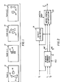
- Such a situation may happen, for instance, in case of scenes that contain a small object 10 moving against a uniform background 12 in the direction of arrow A as shown in Fig. 1., where fields (k), (k+1), and (k+2) represent successive interlaced video fields.
- merging of the fields (k) and (k+1) at a region of interest denoted as the box 14, will result in artifacts due to a false classification of no motion between field (k) and (k+2).
- a consecutive fourth field , field (k+3) in Fig. 1 is used in motion detection, a comparison of fields (k+1) and (k+3), in addition to the comparison of fields at times (k) and (k+2), may increase the reliability of motion detection.
- Video images with dominant motion result, for example, from the motion of hand-held cameras and/or cameras that are panned and zoomed. Since hand-held video cameras are becoming increasingly common in consumer applications, there is a growing interest in a deinterlacing method (e.g., to be used in generating good-quality prints from video) that improves the resolution via motion compensated temporal interpolation, using information contained in neighboring fields.
- a deinterlacing method e.g., to be used in generating good-quality prints from video
- a motion-compensated deinterlacing technique that accounts for dominant motion between fields is discussed by Wang et al. in US 5,134,480, issued July 28, 1992.
- the technique proposed by Wang et al is a time-recursive method that performs motion estimation and compensation on a local basis (for each pixel) via block matching. Due to the time-recursive nature of the method, a history of the deinterlaced versions of the fields that precede the field of interest is utilized.
- a quad-tree hierarchy is used in adjusting the block size in order to increase the accuracy of local motion estimation.
- Deinterlacing is implemented by linearly blending the results of spatial vertical interpolation and motion compensated interpolation, where motion compensation is performed using either the future field following the field of interest or the recursively deinterlaced version of the previous field.
- the object of this invention is to provide a robust method that combines global motion compensation and motion adaptation for deinterlacing in the presence of both dominant motion, such as camera zoom, pan, or jitter, as well as independent local object motion, in order to create a high-quality still image from interlaced video.
- the object is achieved according to one aspect of the present invention, by providing a system and a method for creating a high quality still image from a series of interlaced video fields of the type employing local motion detection between first and third fields of the series, merging the first and second fields in areas of no motion and performing spatial interpolation on the first field in areas containing local motion, wherein the system and method are improved by removing dominant motion from the second and third fields prior to local motion detection.
- the system and method of this invention utilizes motion compensation, and special attention is directed towards producing a robust method in the sense that artifacts generated by motion estimation/compensation failures are minimized.
- the method and system of the present invention is advantageous over the prior art in that it is capable of handling combinations of dominant and local image motion while avoiding complex computation.
- the method of the present invention takes three successive interlaced video fields as inputs, denoted by f 0 ,f 1 ,f 3 respectively, and includes three stages: (i) removing dominant motion from the video fields f 1 , and f 2 , to produce motion compensated second and third fields (16); (ii) detecting local motion in the fields using the first field and the third motion compensated field, and (18); and (iii) merging the first field and the second motion compensated field in regions free of motion and performing spatial interpolation on regions of the first field where motion is detected (20).
- dominant motion is estimated over a user specified region of interest (ROI), to produce the fields f 1 MC and f 2 MC .
- ROI region of interest
- the ROI may be chosen to represent a region in f 0 where there is global motion. Note that it is possible to choose the ROI as the entire field, at the cost of increased computation.
- the local motion detection stage 18 follows, where motion detection is performed to detect regions of video moving with motions that are different from the dominant motion removed in the previous stage 16.
- the local motion detector uses thresholding and is adaptive in the sense that the thresholding operation adapts to the scene contents as described in detail below.
- the output of the motion detection stage 18 is a binary motion/no motion decision map, which is used in the last processing stage 20.
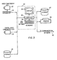
- Input devices such as a video camcorder/VCR 22 connected to a digitizer 24, a digital video camcorder 26, or a disk storage 28 provide a source of a video sequence of digital fields.
- the video sequence of digital fields is then supplied to an image processing computer system 30 that contains a computer 32 such as a Power PC, a CRT display 34 having typically SVGA or better resolution, and an operator input device 36 such as a keyboard or a mouse.
- the computer is connected to an output device such as: a printer 38 for creating a hard copy display of the high-quality still image; a storage medium 40, such as an optical disk, for storage pending eventual display of the image; or link 42 to a communication network for distributing the high-quality still image.
- an output device such as: a printer 38 for creating a hard copy display of the high-quality still image; a storage medium 40, such as an optical disk, for storage pending eventual display of the image; or link 42 to a communication network for distributing the high-quality still image.
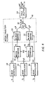
- This stage begins by taking the input fields f 0 , f 1 , and f 2 , and computing the corresponding frames F 0 L , F 1 L , and F 2 L , using spatial vertical linear interpolation. This is depicted as linear interpolators 44 in the block diagram of Fig. 4. Motion is then estimated by motion estimators 46 between the frame pairs F 0 L , F 1 L , and F 0 L , F 2 L . Note that we do not assume constant-velocity, linear-trajectory motion. This is because when the dominant motion is caused by camera jitter the linear motion assumption would be violated.
- F 1 L ( x,y ) F 0 L ( x + c 1+ c 2 x + c 3 y,y + c 4+ c 5 x + c 6 y )
- motion trajectory filtering 48 is used to compute the motion compensated fields f 1 MC and f 2 MC .
- Frames, F 1 L and F 2 L are warped 50 using bilinear spatial interpolation to form frames F 1 W and F 2 W , both of which are estimates of the frame F 0 .
- Frames F 1 W and F 2 W are then temporally averaged 52 to produce the frame F ⁇ 0 MC , which is the motion compensated estimate of F 0 .
- the frame F ⁇ 0 MC is split 54 into an odd and even fields f 1 MC and f 2 MC .
- the motion detection strategy we employ is to compute the summed absolute difference (SAD) over appropriate regions in these two fields, and then apply a thresholding scheme. For example, if we denote the SAD value for the missing pixel location at ( n 1 ,n 2-1) at time index k as S k ( n 1 ,n 2-1) , then the SAD computed over a 3x3 window is given by where represent the corresponding continuous fields sampled over a progressive lattice. If S k ( n 1 ,n 2-1) is larger than a threshold, then motion is detected and a "1" is entered to the corresponding location of the motion detection map array. Otherwise, motion is decided to be not present and a "0" is entered at the corresponding location in the motion detection map. In the following, we describe the method for selecting a dynamic threshold that is spatially adaptive.
- the dominant motion has already been removed, and motion detection applied between the fields f 0 and f 2 MC will be detecting the motion in objects moving independently from the dominant motion.
- motion detection applied between the fields f 0 and f 2 MC will be detecting the motion in objects moving independently from the dominant motion.
- the motion ghost 56 of the small object 10 appears in fields f 1 MC and f 2 MC .
- the ghosting has the positive effect of allowing a 3-field method to detect the motion of fine-detailed objects independently moving against a uniform background, while only comparing a single pair of fields, since the ghost will be present for motion detection.
- the motion detection errors will give rise to artifacts, and these will be most noticeable in image regions of low local variance, especially when no motion is detected. Therefore, in regions of low variance, the comparison threshold used in motion detection should be low, especially for accurate detection of ghosts. Second, in regions of high variance, artifacts due to motion detection will be less noticeable. Additionally, when compared to deinterlacing via an intrafield technique, it is in the regions of higher variance that motion compensated filtering will produce the greatest increase in resolution, and the greatest reduction in aliasing. Therefore, in regions of higher variance the motion detection threshold should be high. This will also provide an implicit tolerance to errors in dominant-motion estimation at such regions, the benefits of such tolerance have been discussed above. The proposed motion detection scheme depicted in Fig. 6 has these properties.
- the first step in the motion detection is to locally estimate 58 a sample standard deviation of field f 0 at every pixel over a 3x3 region, where the pixels lie at the centers of the 3x3 windows.
- the result is a 2-D array, i.e., an image of standard deviation values (S.D. image).
- S.D. image an image of standard deviation values
- the four-level standard deviation image output from the dynamic quantization process is then normalized to the interval [0,1], and used to scale a user specified maximum threshold 62. This results in four thresholds that adapt to regions of lower and higher variance. Each pixel location is assigned to one of these four thresholds. The regions of the largest quantized standard deviation use the specified maximum threshold, and as the standard deviation decreases in the remaining three quantization levels so does the threshold. These thresholds are then applied 64 to the image of SAD values computed 66 between f 0 and f 2 MC , to produce the output motion detection map. We have obtained very good performance when we set the maximum threshold to 20, in case of numerous test images.
- This stage of the present invention creates the final deinterlaced image F ⁇ 0 , on the basis of the motion detection map.
- the lines of f 0 are copied to form the even lines of F ⁇ 0 .
- the motion map from the motion detection stage is used to decide whether to replace the missing pixels in f 0 by merging pixels from f 1 MC (compensated pixels), or by using intrafield interpolation (non-compensated pixels).
- the intrafield interpolation algorithm we propose is an extension of Isnardi's directional interpolation method, where we have incorporated a mechanism for reducing artifacts at areas where contours are not correctly identified.
- the present invention can be applied to multispectral (i.e., color) video as follows. Given the three-channel color video, represented by red, green and blue (R,G,B) channels, a transformation is applied to transform it to a luminance-chrominance space, such as (Y,U,V), where Y denotes the luminance and U and V denote the associated chroma channels. Dominant motion estimation is performed on the luminance channel. The estimated motion is then used in processing red, green and blue channels, separately, according to the invention, to generate the resulting high-quality, color still image.
- a transformation is applied to transform it to a luminance-chrominance space, such as (Y,U,V), where Y denotes the luminance and U and V denote the associated chroma channels.
- Dominant motion estimation is performed on the luminance channel.
- the estimated motion is then used in processing red, green and blue channels, separately, according to the invention, to generate the resulting high-quality, color still image.
Abstract
Description
- This invention relates to a method and system for obtaining a high quality still image from multiple fields of an interlaced video signal, i.e., deinterlacing, in the presence of both dominant motion, such as camera zoom, rotation, pan, or jitter, and local motion of independently moving objects.
- The recent availability of video frame grabbing hardware has allowed video signals to appear on a variety of new platforms, such as multi-media computers and video printing systems. These new platforms have generated a desire in the user to view and print video signals in a different mode than was originally intended, namely as still images. The interlaced video standard, while being sufficient for displaying moving pictures at satisfactory quality, is ineffective for displaying stills since only one half the information needed to display an image is acquired at a single time. As a result, video must be deinterlaced, i.e., converted to progressive video, before it can be viewed as a sequence of stills. The deinterlacing process, which refers to forming frames from fields, is complicated by the possibility that motion can change the scene contents from field to field. Relative motion between fields can be caused by movement of objects in the scene relative to the camera, or by camera changes such as pan, zoom and jitter, where the latter is rather common in hand-held consumer camcorders.
- The prior art addresses the problem of deinterlacing an even (or an odd) field by estimating the missing odd (or even) lines. A well-known method is to merge the even and odd fields, i.e., to fill in the missing lines of the odd (even) field by the lines of the neighboring even (odd) field. This simple mechanism, causes spatial "judder" artifacts at those image regions that contain moving objects (objects that move within the time interval of two successive fields). Merging, however, provides the best spatial resolution at steady image regions. Another approach to deinterlacing is to concentrate on a single field only (e.g., the odd field) and interpolate the missing lines using spatial interpolation. A simple interpolation technique is vertical linear interpolation where an average of the available pixel values above and below the missing pixel is assigned to the missing pixel. This method may cause artifacts if the missing pixel is over an edge whose orientation is not vertical. To overcome these artifacts, an contour-sensitive spatial interpolation method is proposed in M. Isnardi, "Modeling the Television Process," Technical Report No. 515, Massachusetts Institute of Technology, 1986, pages 161 to 163. This method attempts to find the orientation of the image gradient at the missing pixel. Interpolation is then performed using image values that are along this orientation in order not to "cross an edge" and cause artifacts.
- A method that is potentially more effective is a hybrid method where the deinterlacing process switches, on a pixel-by-pixel basis, between merging and spatial interpolation depending on the dynamics of the missing pixel, so that the advantages of merging in steady regions are fully maintained. A motion detection scheme should be used to classify the missing pixel as a "moving pixel" or "steady pixel".
- In US 4,472,732, issued Sept. 18, 1984, Bennett et al. disclose such a method that uses the pixel-by-pixel difference of neighboring fields with the same polarity (e.g., even fields) that follow and precede the field that will be deinterlaced (e.g., an odd field) to perform motion detection, and then switch between merging and vertical interpolation depending on the presence and absence of motion that is determined by thresholding the difference values. This particular approach may falsely detect "no motion" if the scene is such that the gray levels of the pixels being compared in the two neighboring fields are similar although there is motion in the scene. Such a situation may happen, for instance, in case of scenes that contain a
small object 10 moving against auniform background 12 in the direction of arrow A as shown in Fig. 1., where fields (k), (k+1), and (k+2) represent successive interlaced video fields. In this case, merging of the fields (k) and (k+1) at a region of interest denoted as thebox 14, will result in artifacts due to a false classification of no motion between field (k) and (k+2). If a consecutive fourth field , field (k+3) in Fig. 1, is used in motion detection, a comparison of fields (k+1) and (k+3), in addition to the comparison of fields at times (k) and (k+2), may increase the reliability of motion detection. This is evident in the example shown in Fig. 1, where a "moving" decision can be rendered for the region of interest in the frame at time (k+1) as a result of comparing the corresponding image values at fields at times (k+1) and (k+3). Motion-detection based deinterlacing techniques that utilize four consecutive fields, and switch between spatial interpolation and merging, have been discussed in US 4,785,351, issued to Ishikawa, Nov. 15, 1988, and in US 5,021,870 issued to Motoe et al, June 4, 1991.. - These techniques that adapt themselves to the presence of motion are not effective in producing a high quality still image in case of video images that contain dominant motion between fields. In such cases, the above techniques will default to spatial interpolation only, and thus no additional improvement in resolution will be obtained. Video images with dominant motion result, for example, from the motion of hand-held cameras and/or cameras that are panned and zoomed. Since hand-held video cameras are becoming increasingly common in consumer applications, there is a growing interest in a deinterlacing method (e.g., to be used in generating good-quality prints from video) that improves the resolution via motion compensated temporal interpolation, using information contained in neighboring fields.
- A motion-compensated deinterlacing technique that accounts for dominant motion between fields is discussed by Wang et al. in US 5,134,480, issued July 28, 1992. The technique proposed by Wang et al is a time-recursive method that performs motion estimation and compensation on a local basis (for each pixel) via block matching. Due to the time-recursive nature of the method, a history of the deinterlaced versions of the fields that precede the field of interest is utilized. A quad-tree hierarchy is used in adjusting the block size in order to increase the accuracy of local motion estimation. Deinterlacing is implemented by linearly blending the results of spatial vertical interpolation and motion compensated interpolation, where motion compensation is performed using either the future field following the field of interest or the recursively deinterlaced version of the previous field.
- Local motion estimation for every pixel location is in general computationally expensive. Further, it is complicated by the existence of covered/uncovered regions (i.e., occlusions), and sharply varying motion vectors at boundaries of objects that move independent of each other. The challenge for robustness in the case of methods that estimate local motion, thus allowing for independent object motions, is not to create artifacts at motion boundaries. This problem is very difficult to solve in a robust manner without an excessive amount of processing, and is especially difficult in creating high-quality stills from video, since small artifacts can be extremely objectionable. When the motion is modeled globally, using models such as affine or perspective, the challenge is not to produce artifacts when the actual motion deviates from the model.
- The object of this invention is to provide a robust method that combines global motion compensation and motion adaptation for deinterlacing in the presence of both dominant motion, such as camera zoom, pan, or jitter, as well as independent local object motion, in order to create a high-quality still image from interlaced video.
- Briefly summarized, the object is achieved according to one aspect of the present invention, by providing a system and a method for creating a high quality still image from a series of interlaced video fields of the type employing local motion detection between first and third fields of the series, merging the first and second fields in areas of no motion and performing spatial interpolation on the first field in areas containing local motion, wherein the system and method are improved by removing dominant motion from the second and third fields prior to local motion detection.
- The system and method of this invention utilizes motion compensation, and special attention is directed towards producing a robust method in the sense that artifacts generated by motion estimation/compensation failures are minimized. We refer to the motion field estimate obtained on the basis of a global model as the dominant motion. The method and system of the present invention is advantageous over the prior art in that it is capable of handling combinations of dominant and local image motion while avoiding complex computation.
- These and other aspects, objects, features and advantages of the present invention will be more clearly understood and appreciated from a review of the following detailed description of the preferred embodiments and appended claims, and by reference to the accompanying drawings.
-
- Figure 1 shows the prior art methods of detecting motion between successive fields in a video image signal;
- Figure 2 is a block diagram illustrating the major steps of the invention;
- Figure 3 is a schematic diagram depicting a system suitable for implementing the present invention;
- Figure 4 is a detailed block diagram showing the dominant-motion compensated filtering employed in the present invention;
- Figure 5 shows a series of fields demonstrating ghosting when detecting motion in dominant-motion compensated fields; and
- Figure 6 shows a detailed block diagram of adaptive motion detection as employed in the present invention.
- To facilitate understanding, identical reference numerals have been used, where possible, to designate identical elements that are common to the figures.
- Referring to Fig. 2, the method of the present invention takes three successive interlaced video fields as inputs, denoted by f 0 ,f 1 ,f 3 respectively, and includes three stages: (i) removing dominant motion from the video fields f 1 , and f 2 , to produce motion compensated second and third fields (16); (ii) detecting local motion in the fields using the first field and the third motion compensated field, and (18); and (iii) merging the first field and the second motion compensated field in regions free of motion and performing spatial interpolation on regions of the first field where motion is detected (20).
- In the dominant
motion removal stage 16, dominant motion is estimated over a user specified region of interest (ROI), to produce the fields f 1 MC and f 2 MC . Although the described method allows a user to choose a field of interest from video, user selection of a ROI Is not a requirement that limits the usefulness of the method of the present invention. The ROI may be chosen to represent a region in f 0 where there is global motion. Note that it is possible to choose the ROI as the entire field, at the cost of increased computation. The localmotion detection stage 18 follows, where motion detection is performed to detect regions of video moving with motions that are different from the dominant motion removed in theprevious stage 16. The local motion detector uses thresholding and is adaptive in the sense that the thresholding operation adapts to the scene contents as described in detail below. The output of themotion detection stage 18 is a binary motion/no motion decision map, which is used in thelast processing stage 20. - Referring to Fig. 3, a system useful in practicing the present invention is shown. Input devices such as a video camcorder/
VCR 22 connected to adigitizer 24, adigital video camcorder 26, or adisk storage 28 provide a source of a video sequence of digital fields. The video sequence of digital fields is then supplied to an imageprocessing computer system 30 that contains acomputer 32 such as a Power PC, aCRT display 34 having typically SVGA or better resolution, and anoperator input device 36 such as a keyboard or a mouse. The computer is connected to an output device such as: aprinter 38 for creating a hard copy display of the high-quality still image; astorage medium 40, such as an optical disk, for storage pending eventual display of the image; or link 42 to a communication network for distributing the high-quality still image. - The three major stages of the present invention are explained in detail in the following.
- This stage begins by taking the input fields f 0,f 1, and f 2, and computing the corresponding frames F 0 L , F 1 L , and F 2 L , using spatial vertical linear interpolation. This is depicted as
linear interpolators 44 in the block diagram of Fig. 4. Motion is then estimated bymotion estimators 46 between the frame pairs F 0 L , F 1 L , and F 0 L , F 2 L . Note that we do not assume constant-velocity, linear-trajectory motion. This is because when the dominant motion is caused by camera jitter the linear motion assumption would be violated. The global motion is modeled using an affine transformation relating the frames as
- Given the motion parameter sets denoted by P1 and P2 in Fig. 4, corresponding to motion between F 0 L and F 1 L , and F 0 L and F 2 L , respectively,
motion trajectory filtering 48 is used to compute the motion compensated fields f 1 MC and f 2 MC . Frames, F 1 L and F 2 L are warped 50 using bilinear spatial interpolation to form frames F 1 W and F 2 W , both of which are estimates of the frame F 0. Frames F 1 W and F 2 W are then temporally averaged 52 to produce the frame F̂ 0 MC , which is the motion compensated estimate of F 0. Finally the frame F̂ 0 MC is split 54 into an odd and even fields f 1 MC and f 2 MC . - We use the fields f 0 and f 2 MC to perform motion detection. The motion detection strategy we employ is to compute the summed absolute difference (SAD) over appropriate regions in these two fields, and then apply a thresholding scheme. For example, if we denote the SAD value for the missing pixel location at (n1,n2-1) at time index k as S k (n1,n2-1), then the SAD computed over a 3x3 window is given by


- To begin, we note that as a result of the motion compensation step, the dominant motion has already been removed, and motion detection applied between the fields f 0 and f 2 MC will be detecting the motion in objects moving independently from the dominant motion. Because of the global motion assumption made during filtering along the motion trajectory in the motion compensation stage, there will actually be a motion "ghost" present in the field f 2 MC . As shown in Fig. 5, the
motion ghost 56 of thesmall object 10 appears in fields f 1 MC and f 2 MC . The ghosting has the positive effect of allowing a 3-field method to detect the motion of fine-detailed objects independently moving against a uniform background, while only comparing a single pair of fields, since the ghost will be present for motion detection. However, the intensity difference between the background and the ghost is now reduced by a factor of two, due to averaging, compared to the intensity difference between the object itself and the background. Thus, a small threshold is required for detection of motion. The problem now is that if the comparison threshold is set too low, motion will be falsely detected around sharp edges that have undergone global motion but not perfectly compensated for due to inaccuracies in the dominant-motion estimation. To address this problem, we use adaptive thresholding, as explained below. - The following two observations constrain the design of an adaptive thresholding scheme. First, the motion detection errors will give rise to artifacts, and these will be most noticeable in image regions of low local variance, especially when no motion is detected. Therefore, in regions of low variance, the comparison threshold used in motion detection should be low, especially for accurate detection of ghosts. Second, in regions of high variance, artifacts due to motion detection will be less noticeable. Additionally, when compared to deinterlacing via an intrafield technique, it is in the regions of higher variance that motion compensated filtering will produce the greatest increase in resolution, and the greatest reduction in aliasing. Therefore, in regions of higher variance the motion detection threshold should be high. This will also provide an implicit tolerance to errors in dominant-motion estimation at such regions, the benefits of such tolerance have been discussed above. The proposed motion detection scheme depicted in Fig. 6 has these properties.
- In reference to Fig. 6, the first step in the motion detection is to locally estimate 58 a sample standard deviation of field f 0 at every pixel over a 3x3 region, where the pixels lie at the centers of the 3x3 windows. The result is a 2-D array, i.e., an image of standard deviation values (S.D. image). To spatially adapt the threshold to the S.D. image, but remove dependency on abnormally high values for standard deviation, the S.D. image is dynamically quantized 60 into four levels using for example the well known k-means clustering algorithm with k=4 (see J.S. Lim, Two-Dimensional Signal and Image Processing, Prentice Hall, 1990, page 607). The four-level standard deviation image output from the dynamic quantization process is then normalized to the interval [0,1], and used to scale a user specified
maximum threshold 62. This results in four thresholds that adapt to regions of lower and higher variance. Each pixel location is assigned to one of these four thresholds. The regions of the largest quantized standard deviation use the specified maximum threshold, and as the standard deviation decreases in the remaining three quantization levels so does the threshold. These thresholds are then applied 64 to the image of SAD values computed 66 between f 0 and f 2 MC , to produce the output motion detection map. We have obtained very good performance when we set the maximum threshold to 20, in case of numerous test images. - This stage of the present invention creates the final deinterlaced image F̂ 0 , on the basis of the motion detection map. For the even lines, the lines of f 0 are copied to form the even lines of F̂ 0. For the odd lines of F̂ 0, the motion map from the motion detection stage is used to decide whether to replace the missing pixels in f 0 by merging pixels from f 1 MC (compensated pixels), or by using intrafield interpolation (non-compensated pixels). The intrafield interpolation algorithm we propose is an extension of Isnardi's directional interpolation method, where we have incorporated a mechanism for reducing artifacts at areas where contours are not correctly identified.
- A straightforward method of detecting the direction of a contour is to compare the SAD over windows which pivot about the pixel to be interpolated. For example, a 3 pixels by one (3x1) line window would produce a SAD for the direction m denoted by S m , as

- When the slope m is not correctly estimated, artifacts will result. These artifacts occur in regions of fine detail where a well defined contour does not exist. This occurs because the SAD values for each test window pair are resulting in values that are random. As such, the directional choice becomes random. A remedy for this problem is to detect the presence of a well-defined contour, and only use directional interpolation when such a contour is found. A simple but effective means of performing this task is to scale the SAD value for the vertical direction, S 0, by a factor between 0 and 1, so that the decision is biased towards using vertical interpolation. Then, if there is well-defined contour, vertical interpolation is used, but if there is a contour, directional interpolation is used. It has been experimentally determined that the multiplying factor of 0.6 yields a good compromise between detecting the presence of a well defined contour, and providing a satisfactory estimate of the contour direction. We have obtained excellent results with numerous images when SAD is computed over 7x3 windows, and m=2 with slopes computed at 0.5 pixel intervals.
- The present invention can be applied to multispectral (i.e., color) video as follows. Given the three-channel color video, represented by red, green and blue (R,G,B) channels, a transformation is applied to transform it to a luminance-chrominance space, such as (Y,U,V), where Y denotes the luminance and U and V denote the associated chroma channels. Dominant motion estimation is performed on the luminance channel. The estimated motion is then used in processing red, green and blue channels, separately, according to the invention, to generate the resulting high-quality, color still image.
- The invention has been described with reference to a preferred embodiment. However, it will be appreciated that variations and modifications can be effected by a person of ordinary skill in the art without departing from the scope of the invention.
Claims (10)
- In a method for creating a high quality still image from a series of interlaced video fields of the type employing local motion detection between first and third fields of the series, merging the first and second fields in areas of no motion and performing spatial interpolation on the first field in areas containing local motion, the improvement comprising: removing dominant motion from the second and third fields prior to local motion detection.
- The improved method claimed in claim 1, wherein the spatial interpolation is contour sensitive spatial interpolation.
- The improved method claimed in claim 1, wherein the local motion detection employs an adaptive dynamic threshold.
- The improved method claimed in claim 1, wherein the method is applied to a designated region of interest in an image.
- A method for creating a high quality still image from a series of three successive interlaced video fields, comprising the steps of:a. interpolating each field in the series to a full frame to produce a series of interpolated fields;b. estimating the dominant motion of the scene between the first interpolated field and the second and third interpolated fields using a global motion model;c. compensating for the estimated dominant motion in the second and third interpolated fields by warping the second and third interpolated fields to align them with the first interpolated field;d. averaging the second and third warped interpolated fields to provide an averaged dominant motion compensated interpolated field;e. splitting the averaged motion compensated interpolated field to form second and third averaged dominant motion compensated fields;f. detecting local motion between objects in the first field and the third averaged dominant motion compensated field; andg. merging the first field and the second averaged dominant motion compensated field in regions of the image that are free of local motion, and performing contour sensitive spatial interpolation on the first field in areas containing local motion.
- The method for creating a high quality still image claimed in claim 5, further comprising the steps of:a. designating a region of interest in the image for performing the method; andb. performing the method steps on the designated region of interest.
- A system for creating a high quality still image from a series of three interlaced video fields, comprising:a. means for removing dominant motion from the second and third fields to produce dominant motion compensated second and third fields;b. means for detecting local motion between the first field and the third dominant motion compensated field; andc. means for merging the first field and the second dominant motion compensated field in areas of no motion and performing spatial interpolation on the first field in areas containing local motion.
- The system claimed in claim 7, wherein the means for performing spatial interpolation employs contour sensitive spatial interpolation.
- The system claimed in claim 7, wherein the means for local motion detection employs an adaptive dynamic threshold.
- A system for creating a high quality still image from a series of three successive interlaced video fields, comprising:a. means for interpolating each field in the series to a full frame to produced a series of interpolated fields;b. means for estimating the dominant motion of the scene between the first interpolated field and the second and third interpolated fields using a global motion model;c. means for compensating for the estimated dominant motion in the second and third interpolated fields by warping the second and third interpolated fields to align them with the first interpolated field;d. means for averaging the second and third warped interpolated fields to provide an averaged dominant motion compensated interpolated field;e. means for splitting the averaged motion compensated interpolated field to form second and third averaged dominant motion compensated fields;f. detecting local motion between objects in the first field and the third averaged dominant motion compensated field; andg. means for merging the first field and the second averaged dominant motion compensated field in regions of the image that are free of local motion, and performing contour sensitive spatial interpolation on the first field in areas containing local motion to produce the high quality still image.
Applications Claiming Priority (2)
| Application Number | Priority Date | Filing Date | Title |
|---|---|---|---|
| US08/426,309 US5579054A (en) | 1995-04-21 | 1995-04-21 | System and method for creating high-quality stills from interlaced video |
| US426309 | 1995-04-21 |
Publications (2)
| Publication Number | Publication Date |
|---|---|
| EP0739129A2 true EP0739129A2 (en) | 1996-10-23 |
| EP0739129A3 EP0739129A3 (en) | 1998-05-13 |
Family
ID=23690264
Family Applications (1)
| Application Number | Title | Priority Date | Filing Date |
|---|---|---|---|
| EP96420116A Withdrawn EP0739129A3 (en) | 1995-04-21 | 1996-04-09 | A system and method for creating high-quality stills from interlaced video images |
Country Status (3)
| Country | Link |
|---|---|
| US (1) | US5579054A (en) |
| EP (1) | EP0739129A3 (en) |
| JP (1) | JPH08307820A (en) |
Cited By (11)
| Publication number | Priority date | Publication date | Assignee | Title |
|---|---|---|---|---|
| EP0796017A2 (en) * | 1996-03-14 | 1997-09-17 | Matsushita Electric Industrial Co., Ltd | Image data processing apparatus and method |
| WO1998034182A2 (en) * | 1997-02-03 | 1998-08-06 | Koninklijke Philips Electronics N.V. | A method and device for navigating through video matter by means of displaying a plurality of key-frames in parallel |
| WO2000031978A1 (en) * | 1998-11-20 | 2000-06-02 | Koninklijke Philips Electronics N.V. | Performing resolution upscaling on frames of digital video |
| EP1596595A1 (en) * | 2004-05-03 | 2005-11-16 | ATI Technologies Inc. | Apparatus and method for image rendering |
| EP1694066A1 (en) * | 2005-02-18 | 2006-08-23 | Genesis Microchip, Inc. | Global motion adaptive deinterlacing system with motion values correction with respect to luminance level |
| US7471336B2 (en) | 2005-02-18 | 2008-12-30 | Genesis Microchip Inc. | Global motion adaptive system with motion values correction with respect to luminance level |
| US8259228B2 (en) | 2007-12-10 | 2012-09-04 | Ati Technologies Ulc | Method and apparatus for high quality video motion adaptive edge-directional deinterlacing |
| US8300987B2 (en) | 2007-09-28 | 2012-10-30 | Ati Technologies Ulc | Apparatus and method for generating a detail-enhanced upscaled image |
| US8396129B2 (en) | 2007-12-28 | 2013-03-12 | Ati Technologies Ulc | Apparatus and method for single-pass, gradient-based motion compensated image rate conversion |
| US8964117B2 (en) | 2007-09-28 | 2015-02-24 | Ati Technologies Ulc | Single-pass motion adaptive deinterlacer and method therefore |
| CN108141529A (en) * | 2015-09-28 | 2018-06-08 | 高通股份有限公司 | For performing the system and method for autozoom |
Families Citing this family (41)
| Publication number | Priority date | Publication date | Assignee | Title |
|---|---|---|---|---|
| US6052414A (en) * | 1994-03-30 | 2000-04-18 | Samsung Electronics, Co. Ltd. | Moving picture coding method and apparatus for low bit rate systems using dynamic motion estimation |
| DE69602852T2 (en) * | 1995-11-08 | 2000-04-20 | Genesis Microchip Inc | METHOD AND DEVICE FOR SUPPRESSING THE CELL ROPE FROM VIDEO HALF-IMAGES TO VIDEO IMAGES WITH PROGRESSIVE SCANING |
| KR100202565B1 (en) * | 1996-03-23 | 1999-06-15 | 구자홍 | The stereoscopic brightness/chrominance separating apparatus of composite image signal |
| JPH09307857A (en) * | 1996-05-17 | 1997-11-28 | Sony Corp | Image signal processing unit and image signal processing method |
| WO1998009436A1 (en) * | 1996-08-30 | 1998-03-05 | Sony Corporation | Device, method, and medium for recording still picture and animation |
| US6205178B1 (en) * | 1996-09-20 | 2001-03-20 | Hitachi, Ltd. | Method and synthesizing a predicted image, video coding device and video coding method |
| US5784115A (en) * | 1996-12-31 | 1998-07-21 | Xerox Corporation | System and method for motion compensated de-interlacing of video frames |
| US6122017A (en) * | 1998-01-22 | 2000-09-19 | Hewlett-Packard Company | Method for providing motion-compensated multi-field enhancement of still images from video |
| AU733040B2 (en) * | 1998-06-19 | 2001-05-03 | Canon Kabushiki Kaisha | A method of identifying image frames suitable for printing |
| US6304682B1 (en) * | 1998-10-02 | 2001-10-16 | Hewlett-Packard Company | Method for generated resolution enhanced still images from compressed video data |
| US6414760B1 (en) | 1998-10-29 | 2002-07-02 | Hewlett-Packard Company | Image scanner with optical waveguide and enhanced optical sampling rate |
| US6285804B1 (en) | 1998-12-21 | 2001-09-04 | Sharp Laboratories Of America, Inc. | Resolution improvement from multiple images of a scene containing motion at fractional pixel values |
| US6348949B1 (en) * | 1998-12-22 | 2002-02-19 | Intel Corporation | Deinterlacing a video signal using a motion detector |
| US7068329B1 (en) * | 1999-08-31 | 2006-06-27 | Ati International Srl | Method and system for providing a video signal |
| US6459455B1 (en) * | 1999-08-31 | 2002-10-01 | Intel Corporation | Motion adaptive deinterlacing |
| US6466618B1 (en) | 1999-11-19 | 2002-10-15 | Sharp Laboratories Of America, Inc. | Resolution improvement for multiple images |
| US6842196B1 (en) * | 2000-04-04 | 2005-01-11 | Smith & Nephew, Inc. | Method and system for automatic correction of motion artifacts |
| US6665450B1 (en) * | 2000-09-08 | 2003-12-16 | Avid Technology, Inc. | Interpolation of a sequence of images using motion analysis |
| US6734916B1 (en) * | 2000-10-04 | 2004-05-11 | Karl Sims | Video field artifact removal |
| US7043058B2 (en) * | 2001-04-20 | 2006-05-09 | Avid Technology, Inc. | Correcting motion vector maps for image processing |
| US7545957B2 (en) * | 2001-04-20 | 2009-06-09 | Avid Technology, Inc. | Analyzing motion of characteristics in images |
| US6847405B2 (en) * | 2001-09-14 | 2005-01-25 | Sony Corporation | Motion-adaptive de-interlacing method and system for digital televisions |
| US6647152B2 (en) * | 2002-01-25 | 2003-11-11 | Thomson Licensing S.A. | Method and system for contouring reduction |
| US7194676B2 (en) | 2002-03-01 | 2007-03-20 | Avid Technology, Inc. | Performance retiming effects on synchronized data in an editing system |
| US7085323B2 (en) * | 2002-04-03 | 2006-08-01 | Stmicroelectronics, Inc. | Enhanced resolution video construction method and apparatus |
| KR20040061244A (en) * | 2002-12-30 | 2004-07-07 | 삼성전자주식회사 | Method and apparatus for de-interlacing viedo signal |
| US7242435B2 (en) * | 2003-04-18 | 2007-07-10 | Silicon Integrated Systems Corp. | Method for motion pixel detection with adaptive thresholds |
| TWI220366B (en) * | 2003-08-11 | 2004-08-11 | Mediatek Inc | Scalable video format conversion system |
| US7199838B2 (en) * | 2004-06-17 | 2007-04-03 | Samsung Electronics Co., Ltd. | Motion adaptive noise reduction apparatus and method for video signals |
| US8624980B2 (en) * | 2004-08-10 | 2014-01-07 | Thomson Licensing | Apparatus and method for indicating the detected degree of motion in video |
| US7522214B1 (en) * | 2005-06-27 | 2009-04-21 | Magnum Semiconductor, Inc. | Circuits and methods for deinterlacing video display data and systems using the same |
| TWI297994B (en) * | 2005-12-08 | 2008-06-11 | Inst Information Industry | Encoder, method for adjusting decoding calculation, and computer readable record medium therefor |
| JP4303745B2 (en) * | 2006-11-07 | 2009-07-29 | シャープ株式会社 | Image display apparatus and method, image processing apparatus and method |
| US8279341B1 (en) * | 2007-02-26 | 2012-10-02 | MotionDSP, Inc. | Enhancing the resolution and quality of sequential digital images |
| US8494234B1 (en) | 2007-03-07 | 2013-07-23 | MotionDSP, Inc. | Video hashing system and method |
| US20090002556A1 (en) * | 2007-06-11 | 2009-01-01 | Picongen Wireless Inc. | Method and Apparatus for Packet Insertion by Estimation |
| US8345157B2 (en) * | 2007-09-28 | 2013-01-01 | Canon Kabushiki Kaisha | Image processing apparatus and image processing method thereof |
| US8001473B1 (en) * | 2008-01-18 | 2011-08-16 | Adobe Systems Incorporated | Methods and systems for generating a composition |
| US8750645B2 (en) * | 2009-12-10 | 2014-06-10 | Microsoft Corporation | Generating a composite image from video frames |
| US10110805B2 (en) | 2012-12-06 | 2018-10-23 | Sandisk Technologies Llc | Head mountable camera system |
| US10061349B2 (en) | 2012-12-06 | 2018-08-28 | Sandisk Technologies Llc | Head mountable camera system |
Citations (7)
| Publication number | Priority date | Publication date | Assignee | Title |
|---|---|---|---|---|
| US4472732A (en) * | 1981-04-10 | 1984-09-18 | Ampex Corporation | System for spatially transforming images |
| DE3444836A1 (en) * | 1984-12-08 | 1986-06-12 | Robert Bosch Gmbh, 7000 Stuttgart | Method for converting a video signal |
| US4785351A (en) * | 1985-11-29 | 1988-11-15 | Canon Kabushiki Kaisha | Picture signal converting device |
| US4868655A (en) * | 1987-11-09 | 1989-09-19 | Etat Francais Represente Par Le Ministre Delegue Des Postes Et Telecommunications (Centre National D'etudes Des Telecommunications) | Method and apparatus for processing picture signals having interlaced field scanning |
| US4985764A (en) * | 1988-09-29 | 1991-01-15 | Kabushiki Kaisha Toshiba | Apparatus for detecting a pixel correlation and generating an interpolation signal for a digital television signal |
| US5021870A (en) * | 1988-07-19 | 1991-06-04 | Sony Corporation | Interpolation of scan lines from video signals having interlaced scan lines |
| US5134480A (en) * | 1990-08-31 | 1992-07-28 | The Trustees Of Columbia University In The City Of New York | Time-recursive deinterlace processing for television-type signals |
Family Cites Families (2)
| Publication number | Priority date | Publication date | Assignee | Title |
|---|---|---|---|---|
| JP2762794B2 (en) * | 1991-10-15 | 1998-06-04 | 松下電器産業株式会社 | Scan line interpolator |
| US5410356A (en) * | 1991-04-19 | 1995-04-25 | Matsushita Electric Industrial Co., Ltd. | Scanning-line interpolation apparatus |
-
1995
- 1995-04-21 US US08/426,309 patent/US5579054A/en not_active Expired - Lifetime
-
1996
- 1996-04-09 EP EP96420116A patent/EP0739129A3/en not_active Withdrawn
- 1996-04-18 JP JP8096384A patent/JPH08307820A/en active Pending
Patent Citations (7)
| Publication number | Priority date | Publication date | Assignee | Title |
|---|---|---|---|---|
| US4472732A (en) * | 1981-04-10 | 1984-09-18 | Ampex Corporation | System for spatially transforming images |
| DE3444836A1 (en) * | 1984-12-08 | 1986-06-12 | Robert Bosch Gmbh, 7000 Stuttgart | Method for converting a video signal |
| US4785351A (en) * | 1985-11-29 | 1988-11-15 | Canon Kabushiki Kaisha | Picture signal converting device |
| US4868655A (en) * | 1987-11-09 | 1989-09-19 | Etat Francais Represente Par Le Ministre Delegue Des Postes Et Telecommunications (Centre National D'etudes Des Telecommunications) | Method and apparatus for processing picture signals having interlaced field scanning |
| US5021870A (en) * | 1988-07-19 | 1991-06-04 | Sony Corporation | Interpolation of scan lines from video signals having interlaced scan lines |
| US4985764A (en) * | 1988-09-29 | 1991-01-15 | Kabushiki Kaisha Toshiba | Apparatus for detecting a pixel correlation and generating an interpolation signal for a digital television signal |
| US5134480A (en) * | 1990-08-31 | 1992-07-28 | The Trustees Of Columbia University In The City Of New York | Time-recursive deinterlace processing for television-type signals |
Cited By (17)
| Publication number | Priority date | Publication date | Assignee | Title |
|---|---|---|---|---|
| EP0796017A2 (en) * | 1996-03-14 | 1997-09-17 | Matsushita Electric Industrial Co., Ltd | Image data processing apparatus and method |
| EP0796017A3 (en) * | 1996-03-14 | 2000-12-13 | Matsushita Electric Industrial Co., Ltd | Image data processing apparatus and method |
| US6266081B1 (en) | 1996-03-14 | 2001-07-24 | Matsushita Electric Industrial Co., Ltd. | Digital image data storage, data transfer and data broadcast apparatus and method |
| WO1998034182A2 (en) * | 1997-02-03 | 1998-08-06 | Koninklijke Philips Electronics N.V. | A method and device for navigating through video matter by means of displaying a plurality of key-frames in parallel |
| WO1998034182A3 (en) * | 1998-01-22 | 1998-10-08 | Koninkl Philips Electronics Nv | A method and device for navigating through video matter by means of displaying a plurality of key-frames in parallel |
| WO2000031978A1 (en) * | 1998-11-20 | 2000-06-02 | Koninklijke Philips Electronics N.V. | Performing resolution upscaling on frames of digital video |
| EP1596595A1 (en) * | 2004-05-03 | 2005-11-16 | ATI Technologies Inc. | Apparatus and method for image rendering |
| US7633549B2 (en) | 2004-05-03 | 2009-12-15 | Ati Technologies, Inc. | Apparatus and method for image rendering |
| US7471336B2 (en) | 2005-02-18 | 2008-12-30 | Genesis Microchip Inc. | Global motion adaptive system with motion values correction with respect to luminance level |
| EP1694066A1 (en) * | 2005-02-18 | 2006-08-23 | Genesis Microchip, Inc. | Global motion adaptive deinterlacing system with motion values correction with respect to luminance level |
| US7675573B2 (en) | 2005-02-18 | 2010-03-09 | Genesis Microchip Inc. | Global motion adaptive system with motion values correction with respect to luminance level |
| US8300987B2 (en) | 2007-09-28 | 2012-10-30 | Ati Technologies Ulc | Apparatus and method for generating a detail-enhanced upscaled image |
| US8964117B2 (en) | 2007-09-28 | 2015-02-24 | Ati Technologies Ulc | Single-pass motion adaptive deinterlacer and method therefore |
| US8259228B2 (en) | 2007-12-10 | 2012-09-04 | Ati Technologies Ulc | Method and apparatus for high quality video motion adaptive edge-directional deinterlacing |
| US8396129B2 (en) | 2007-12-28 | 2013-03-12 | Ati Technologies Ulc | Apparatus and method for single-pass, gradient-based motion compensated image rate conversion |
| CN108141529A (en) * | 2015-09-28 | 2018-06-08 | 高通股份有限公司 | For performing the system and method for autozoom |
| CN108141529B (en) * | 2015-09-28 | 2019-03-01 | 高通股份有限公司 | System and method for executing autozoom |
Also Published As
| Publication number | Publication date |
|---|---|
| EP0739129A3 (en) | 1998-05-13 |
| US5579054A (en) | 1996-11-26 |
| JPH08307820A (en) | 1996-11-22 |
Similar Documents
| Publication | Publication Date | Title |
|---|---|---|
| US5579054A (en) | System and method for creating high-quality stills from interlaced video | |
| US5661525A (en) | Method and apparatus for converting an interlaced video frame sequence into a progressively-scanned sequence | |
| US5602654A (en) | Contour-sensitive, single-field deinterlacing method | |
| EP0395274B1 (en) | Motion dependent video signal processing | |
| EP0395275B1 (en) | Motion dependent video signal processing | |
| EP0395271B1 (en) | Motion dependent video signal processing | |
| US5784115A (en) | System and method for motion compensated de-interlacing of video frames | |
| Patti et al. | Robust methods for high-quality stills from interlaced video in the presence of dominant motion | |
| US8054380B2 (en) | Method and apparatus for robust super-resolution video scaling | |
| US7075988B2 (en) | Apparatus and method of converting frame and/or field rate using adaptive motion compensation | |
| US5682205A (en) | Adaptive, global-motion compensated deinterlacing of sequential video fields with post processing | |
| US20050201626A1 (en) | Global motion-compensated sequential-scanning method considering horizontal and vertical patterns | |
| US5012337A (en) | Motion dependent video signal processing | |
| EP0395265A2 (en) | Motion dependent video signal processing | |
| EP0395276B1 (en) | Video signal to photographic film conversion | |
| US20060045365A1 (en) | Image processing unit with fall-back | |
| US20050129124A1 (en) | Adaptive motion compensated interpolating method and apparatus | |
| EP0395268B1 (en) | Motion dependent video signal processing | |
| EP0395266B1 (en) | Motion dependent video signal processing | |
| EP0395272B1 (en) | Motion dependent video signal processing | |
| EP0395270B1 (en) | Motion dependent video signal processing | |
| US20020001347A1 (en) | Apparatus and method for converting to progressive scanning format | |
| US7679676B2 (en) | Spatial signal conversion | |
| EP0395269B1 (en) | Motion dependent video signal processing | |
| US6307560B1 (en) | Classified adaptive spatio-temporal format conversion method and apparatus |
Legal Events
| Date | Code | Title | Description |
|---|---|---|---|
| PUAI | Public reference made under article 153(3) epc to a published international application that has entered the european phase |
Free format text: ORIGINAL CODE: 0009012 |
|
| AK | Designated contracting states |
Kind code of ref document: A2 Designated state(s): DE FR GB |
|
| PUAL | Search report despatched |
Free format text: ORIGINAL CODE: 0009013 |
|
| AK | Designated contracting states |
Kind code of ref document: A3 Designated state(s): DE FR GB |
|
| 17P | Request for examination filed |
Effective date: 19981109 |
|
| 17Q | First examination report despatched |
Effective date: 20020704 |
|
| STAA | Information on the status of an ep patent application or granted ep patent |
Free format text: STATUS: THE APPLICATION IS DEEMED TO BE WITHDRAWN |
|
| 18D | Application deemed to be withdrawn |
Effective date: 20021115 |