EP0740109A2 - Fluidized-bed combuster - Google Patents
Fluidized-bed combuster Download PDFInfo
- Publication number
- EP0740109A2 EP0740109A2 EP95114336A EP95114336A EP0740109A2 EP 0740109 A2 EP0740109 A2 EP 0740109A2 EP 95114336 A EP95114336 A EP 95114336A EP 95114336 A EP95114336 A EP 95114336A EP 0740109 A2 EP0740109 A2 EP 0740109A2
- Authority
- EP
- European Patent Office
- Prior art keywords
- fluidized
- diffuser plate
- bed
- incombustible material
- fluidizing gas
- Prior art date
- Legal status (The legal status is an assumption and is not a legal conclusion. Google has not performed a legal analysis and makes no representation as to the accuracy of the status listed.)
- Granted
Links
Images


Classifications
-
- F—MECHANICAL ENGINEERING; LIGHTING; HEATING; WEAPONS; BLASTING
- F23—COMBUSTION APPARATUS; COMBUSTION PROCESSES
- F23G—CREMATION FURNACES; CONSUMING WASTE PRODUCTS BY COMBUSTION
- F23G5/00—Incineration of waste; Incinerator constructions; Details, accessories or control therefor
- F23G5/30—Incineration of waste; Incinerator constructions; Details, accessories or control therefor having a fluidised bed
-
- F—MECHANICAL ENGINEERING; LIGHTING; HEATING; WEAPONS; BLASTING
- F23—COMBUSTION APPARATUS; COMBUSTION PROCESSES
- F23C—METHODS OR APPARATUS FOR COMBUSTION USING FLUID FUEL OR SOLID FUEL SUSPENDED IN A CARRIER GAS OR AIR
- F23C10/00—Fluidised bed combustion apparatus
- F23C10/02—Fluidised bed combustion apparatus with means specially adapted for achieving or promoting a circulating movement of particles within the bed or for a recirculation of particles entrained from the bed
- F23C10/12—Fluidised bed combustion apparatus with means specially adapted for achieving or promoting a circulating movement of particles within the bed or for a recirculation of particles entrained from the bed the particles being circulated exclusively within the combustion zone
- F23C10/14—Fluidised bed combustion apparatus with means specially adapted for achieving or promoting a circulating movement of particles within the bed or for a recirculation of particles entrained from the bed the particles being circulated exclusively within the combustion zone the circulating movement being promoted by inducing differing degrees of fluidisation in different parts of the bed
-
- F—MECHANICAL ENGINEERING; LIGHTING; HEATING; WEAPONS; BLASTING
- F23—COMBUSTION APPARATUS; COMBUSTION PROCESSES
- F23C—METHODS OR APPARATUS FOR COMBUSTION USING FLUID FUEL OR SOLID FUEL SUSPENDED IN A CARRIER GAS OR AIR
- F23C10/00—Fluidised bed combustion apparatus
- F23C10/18—Details; Accessories
- F23C10/20—Inlets for fluidisation air, e.g. grids; Bottoms
-
- F—MECHANICAL ENGINEERING; LIGHTING; HEATING; WEAPONS; BLASTING
- F23—COMBUSTION APPARATUS; COMBUSTION PROCESSES
- F23G—CREMATION FURNACES; CONSUMING WASTE PRODUCTS BY COMBUSTION
- F23G2203/00—Furnace arrangements
- F23G2203/50—Fluidised bed furnace
-
- F—MECHANICAL ENGINEERING; LIGHTING; HEATING; WEAPONS; BLASTING
- F23—COMBUSTION APPARATUS; COMBUSTION PROCESSES
- F23G—CREMATION FURNACES; CONSUMING WASTE PRODUCTS BY COMBUSTION
- F23G2203/00—Furnace arrangements
- F23G2203/50—Fluidised bed furnace
- F23G2203/502—Fluidised bed furnace with recirculation of bed material inside combustion chamber
Definitions
- the present invention relates to a fluidized-bed combustor for combusting solid combustible material containing incombustible material, e.g., industrial waste, municipal garbage, coal, etc. in a fluidized-bed furnace, and more particularly to a fluidized-bed combustor for discharging incombustible material smoothly from a fluidized-bed furnace to avoid a deposit of incombustible material in a certain location in the fluidized-bed furnace and uniformly combusting solid combustible material to recover thermal energy stably therefrom.
- incombustible material e.g., industrial waste, municipal garbage, coal, etc.
- JP-A No. 4-214110 discloses a fluidized-bed combustor which combusts waste material containing incombustible material in a fluidized-bed furnace, and discharges the incombustible material smoothly from the fluidized-bed furnace to allow the waste material to be combusted stably in the fluidized-bed furnace.
- an incombustible material discharge port 50 is defined between an air diffuser plate 40 and a furnace wall, and the air diffuser plate 40 has an inclined upper surface 44 inclined such that the incombustible material discharge port 50 is located in a lower position.
- the air diffuser plate 40 supplies more air to a lower region of the air diffuser plate 40 than to a higher region of the air diffuser plate 40.
- a fluidized bed has a characteristic similar to liquid. Therefore, material of larger specific gravity than the fluidized medium descends in the fluidized bed, and material of smaller specific gravity than the fluidized medium floats in the fluidized bed, thus creating so-called specific gravity separation.
- incombustible material of a large specific gravity descends in the fluidized bed, and deposited on the bottom of the furnace before reaching the incombustible material discharge port 50.
- the incombustible material discharge port 50 to which a fluidizing gas is not supplied is open in the bottom of the furnace, the fluidized bed above the incombustible material discharge port 50 is not stabilized.
- a fluidized-bed combustor shown in FIG. 11 of the above publication (No. 4-214110) has air diffuser plates 90a, 90b having respective downwardly inclined surfaces which extend from the center of a fluidized-bed furnace toward two incombustible material discharge ports 95a, 95b, and air diffuser plates 90c, 90d having respective downwardly inclined surfaces which extend from a furnace side wall toward the incombustible material discharge ports 95a, 95b. While more air is supplied from the regions of the air diffuser plate next to those incombustible material discharge ports through air chambers 93c, 93e than from other regions, a fluidized bed in which a fluidized medium is intensely fluidized by a large amount of air supplied thereto has a characteristic similar to liquid.
- the incombustible material discharge ports in which a fluidizing gas is not introduced are open in the bottom of the furnace as viewed in plan, a fixed bed in which the fluidized medium is not fluidized is formed at the region near or above the incombustible material discharge ports. Therefore, the fixed bed prevents a circulating flow in the fluidized bed from being formed, dispersion and mixture of combustible material in the fluidized bed are not effectively carried out, and incombustible material cannot be smoothly discharged out of the furnace.
- JP-B2 Japanese patent publication (JP-B2) No. 5-19044 discloses a fluidized-bed furnace for incinerating waste material containing incombustible material such as metal pieces, soil, and rocks.
- the disclosed fluidized-bed furnace has a furnace bed including downwardly inclined surfaces extending toward an incombustible material discharge port 5 disposed centrally in the furnace bed. Fluidizing air is supplied such that the amount of fluidizing air per unit area of the furnace bed is larger in the vicinity of the incombustible material discharge port and decreases stepwise toward a furnace side wall.
- incombustible material e.g., industrial waste, municipal garbage, coal, etc.
- Incombustible material of a large specific gravity such as iron or the like, is less susceptible to descending and capable of moving horizontally when supported by a moving bed (the transient state of a fluidized medium between a fixed bed and a fluidized bed), but is quickly settled down and deposited and cannot easily be moved in a fluidized bed in which the fluidized medium is violently fluidized. Thus, it is difficult to discharge the incombustible material out of the furnace.
- a specific object of the present invention to provide a fluidized-bed combustor which is capable of moving combustible material containing incombustible material supplied into a fluidized-bed furnace to a position in the vicinity of an incombustible material discharge port with a fluidized medium, violently fluidizing the fluidized medium and rapidly combusting the combustible material in the vicinity of the incombustible material discharge port, and settling and separating incombustible material of a large specific gravity to discharge it from the incombustible material discharge port.
- Another object of the present invention is to provide a fluidized-bed combustor in which the flow of a fluidizing gas is not interrupted by an incombustible material discharge port to thereby stabilize a main fluidized bed and a main circulating flow of a fluidized medium which are produced in a fluidized-bed furnace for combusting combustible material effectively.
- Still another object of the present invention is to provide a fluidized-bed combustor in which while combustible material containing incombustible material supplied into a fluidized-bed furnace is moving in descending and horizontal flows of a fluidized medium, the combustible material is separated by a selective action of a fluidizing gas into an upper fluidized bed having a high combustible material concentration with a small specific gravity and a lower fluidized bed having a high incombustible material concentration with a large specific gravity, the upper fluidized bed flows beyond an incombustible material discharge port and is mixed with an upward flow for further circulation, and the incombustible material and fluidized medium in the lower fluidized bed are extracted with priority out of the fluidized-bed furnace through the incombustible material discharge port.
- Yet still another object of the present invention is to provide a fluidized-bed combustor which is capable of effectively discharging incombustible material out of a fluidized-bed furnace, and has a heat collector disposed in an auxiliary fluidized bed that is produced separately from a main fluidized bed, for stably recovering thermal energy.
- a fluidized-bed combustor for combusting combustible material containing incombustible material in a fluidized-bed furnace, comprising: a first diffuser plate disposed at a bottom of the fluidized-bed furnace and having a plurality of holes for supplying a fluidizing gas with a relatively low fluidizing gas velocity; a second diffuser plate disposed at a bottom of the fluidized-bed furnace and having a plurality of holes for supplying a fluidizing gas with a relatively high fluidizing gas velocity; an incombustible material discharge port for discharging the incombustible material out of the fluidized-bed furnace, the incombustible material discharge port being defined between the first diffuser plate and the second diffuser plate; a combustible material supply port disposed above the first diffuser plate for supplying the combustible material into the fluidized-bed furnace; and a diffuser device for supplying a fluidizing gas through the incombustible material discharge port into the
- the fluidized medium forms a main circulating flow which includes descending and upward flows.
- a fluidizing gas is supplied from the incombustible material discharge port to continue a main fluidized bed in the vicinity of the incombustible material discharge port for thereby stabilizing the main circulating flow.
- the upper fluidized bed flows beyond the incombustible material discharge port and is mixed with the upward flow of the moving fluidized medium for further circulation and combustion.
- the incombustible material and the fluidized medium in the lower fluidized bed are extracted with priority out of the fluidized-bed furnace through the incombustible material discharge port.
- the fluidized-bed combustor further comprises an auxiliary diffuser plate disposed between the first diffuser plate and the incombustible material discharge port, the auxiliary diffuser plate having a plurality of fluidizing gas supply holes defined therein for supplying a fluidizing gas so as to fluidize the fluidized medium at a relatively high fluidizing speed, the auxiliary diffuser plate having a downwardly inclined surface extending between a lower edge of the first diffuser plate and the incombustible material discharge port and being steeper than the first diffuser plate.
- the fluidized-bed furnace has an inclined wall disposed above the second diffuser plate for directing the fluidizing gas and the fluidized medium flowing upwardly of the second diffuser plate toward a region above the first diffuser plate, i.e., a central region of the fluidized-bed furnace.
- a free board is disposed above the inclined wall.
- the second diffuser plate has an upwardly inclined surface which is progressively higher away from the incombustible material discharge port and supplies the fluidizing gas having a progressively increasing fluidizing gas velocity away from the incombustible material discharge port.
- the fluidized-bed combustor also comprises a thermal energy recovery chamber defined between the inclined wall and a side wall of the fluidized-bed furnace and being in communication with the central region of the fluidized-bed furnace above and below the inclined wall; a heat collector disposed in the thermal energy recovery chamber for recovering thermal energy from the fluidized medium in the thermal energy recovery chamber; and a third diffuser plate disposed between the second diffuser plate and the side wall of the fluidized-bed furnace and extending contiguously to an outer edge of the second diffuser plate, the third diffuser plate having a plurality of holes for supplying a fluidizing gas with a relatively low fluidizing gas velocity; wherein the third diffuser plate has an upwardly inclined surface which has the same gradient as the second diffuser plate and supplies the fluidizing gas to fluidize the fluidized medium at a relatively low fluidizing speed in the thermal energy recovery chamber.
- the bottom of the fluidized-bed furnace may be of a rectangular or circular shape. If the bottom of the fluidized-bed furnace is of a rectangular shape, then the first diffuser plate, the incombustible discharge port, and the second diffuser plate, which are of a rectangular shape, may be disposed parallel to each other, or alternatively, the incombustible material discharge port and the second diffuser plate, which are of a rectangular shape, may be disposed symmetrically with respect to a ridge of the first diffuser plate which is of a rectangular, roof-shaped structure.
- the circular bottom of the fluidized-bed furnace is composed of the first diffuser plate which is of a conical shape having a central region higher than a circumferential edge thereof, the incombustible material discharge port comprising a plurality of arcuate sections disposed concentrically with the first diffuser plate, and the second diffuser plate which is of an annular shape disposed concentrically with the first diffuser plate.
- a fluidized-bed combustor for combusting combustible material containing incombustible material in a fluidized-bed furnace, comprising: a first diffuser plate disposed at a bottom of the fluidized-bed furnace and having a plurality of holes for supplying a fluidizing gas with a relatively low fluidizing gas velocity; an auxiliary diffuser plate disposed at a bottom of the fluidized-bed furnace and having a plurality of holes for supplying a fluidizing gas with a relatively high fluidizing gas velocity; a second diffuser plate disposed at a bottom of the fluidized-bed furnace and having a plurality of holes for supplying a fluidizing gas with a relatively high fluidizing gas velocity; an incombustible material discharge port for discharging the incombustible material out of the fluidized-bed furnace, the incombustible material discharge port being defined between the auxiliary diffuser plate and the second diffuser plate; and a combustible material supply port disposed above the
- the fluidized-bed furnace has an inclined wall disposed above the second diffuser plate for directing the fluidizing gas and the fluidized medium flowing upwardly of the second diffuser plate toward a region above the first diffuser plate, i.e., a central region of the fluidized-bed furnace.
- a free board is disposed above the inclined wall.
- the second diffuser plate has an upwardly inclined surface which is progressively higher away from the incombustible material discharge port and supplies the fluidizing gas having a progressively increasing fluidizing gas velocity away from the incombustible material discharge port.
- the fluidized-bed combustor also has a thermal energy recovery chamber defined between the inclined wall and a side wall of the fluidized-bed furnace and being in communication with the central region of the fluidized-bed furnace above and below the inclined wall; a heat collector disposed in the thermal energy recovery chamber for recovering thermal energy from the fluidized medium in the thermal energy recovery chamber; and a third diffuser plate disposed between the second diffuser plate and the side wall of the fluidized-bed furnace and extending contiguously to an outer edge of the second diffuser plate, the third diffuser plate having a plurality of holes for supplying a fluidizing gas with a relatively low fluidizing gas velocity; wherein the third diffuser plate has an upwardly inclined surface which has the same gradient as the second diffuser plate and supplies the fluidizing gas to fluidize the fluidized medium at a relatively low fluidizing speed in the thermal energy recovery chamber.
- the bottom of the fluidized-bed furnace may be of a rectangular or circular shape. If the bottom of the fluidized-bed furnace is of a rectangular shape, then the first diffuser plate, and the second diffuser plate, which are of a rectangular shape, may be disposed parallel to each other, or alternatively, the first diffuser plate and the second diffuser plate, which are of a rectangular shape, may be disposed symmetrically with respect to a ridge of the first diffuser plate which is of a rectangular, roof-shaped structure.
- the circular bottom of the fluidized-bed furnace is composed of the first diffuser plate which is of a conical shape, the second diffuser plate which is of an inverted conical shape disposed concentrically with the first diffuser plate, and the incombustible material discharge port which is open in the vertical gap between the outer circumferential edge of the first diffuser plate and the inner circumferential edge of the second diffuser plate.
- a fluidizing gas such as air supplied from the first diffuser plate fluidizes a fluidized medium at a relatively low fluidizing speed to create a descending flow of the fluidized medium
- a fluidizing gas such as air supplied from the second diffuser plate fluidizes the fluidized medium at a relatively high fluidizing speed to create an upward flow of the fluidized medium, thus producing a main circulating fluidized bed including the descending and upward flows.
- the fluidized medium descends with the descending flow, it is guided by the downwardly inclined surface of the first diffuser plate, and ascends with the upward flow in the vicinity of the second diffuser plate. Having reached an upper region of the fluidized bed, the fluidized medium is directed to the central region of the fluidized-bed furnace, and then descends with the descending flow again, with the result that a main circulating flow is generated which circulates in the main fluidized bed.
- the fluidized medium in the region near or above the incombustible material discharge port is fluidized intensely.
- a fluidized region of the fluidized medium continues from the first diffuser plate to the second diffuser plate, and a circulating flow including a descending flow in the weak fluidized region and an upward flow in the intense fluidized region is stably formed without interrupted.
- the inclined wall above the second diffuser plate directs the fluidizing gas and the fluidized medium ascending upwardly of the second diffuser plate toward the central region of the fluidized-bed furnace, thereby promoting the formation of the main circulating flow.
- Combustible material containing incombustible material is supplied to a location above the first diffuser plate from the combustible material supply port.
- the fluidized medium above the first diffuser plate is slowly fluidized, and a moving bed of an intermediate state between a fixed bed and a fluidized bed is formed. Since the combustible material and the incombustible material is suspended in the fluidized medium of the moving bed, they descend together with the circulating flow in the fluidized bed, and then move horizontally toward a fluidized region above the second diffuser plate which supplies a fluidizing gas with a relatively large fluidizing gas velocity.
- the fluidized medium is slowly fluidized, and material of larger specific gravity than the bulk density of the moving bed descends gradually and material of smaller specific gravity than the bulk density of the moving bed floats during the horizontal flow of the fluidized medium, thus creating specific gravity separation.
- the combustible material of a small specific gravity moves toward an upper region of the horizontal flow and the incombustible material of a large specific gravity moves toward a lower region of the horizontal flow.
- an upper fluidized bed having a high combustible material concentration with a small specific gravity and a lower fluidized bed having a high incombustible material concentration with a large specific gravity are produced from the combustible material in the horizontal flow in the vicinity of the incombustible material discharge port.
- the upper fluidized bed flows beyond the incombustible material discharge port and is mixed with the upward flow of the fluidized medium, and the combustible material in the fluidized bed is combusted in an oxidizing atmosphere and intensive fluidization. Since the upper fluidized bed has a relatively low incombustible material concentration, the combustible material in the fluidized bed is effectively combusted in the upward flow of the fluidized medium.
- the lower fluidised bed having a large incombustible material concentration with a large specific gravity is guided by the downwardly inclined upper surface of the first diffuser plate toward the incombustible material discharge port, and a part of the fluidized medium and the incombustible material in the lower fluidized bed are extracted from the incombustible material discharge port. Since the fluidized medium above the first diffuser plate is in the state of a moving bed, the incombustible material of a large specific gravity, such as iron or the like is supported by the moving bed, moved toward the incombustible material discharge port, and is not deposited on the bottom of the fluidized-bed furnace.
- the fluidized medium is fluidized intensely at the region near or above the incombustible material discharge port.
- the fluidized bed has a characteristic similar to liquid. Therefore, material of larger specific gravity than the bulk density of the fluidized bed descends and material of smaller specific gravity floats in the fluidized bed, thus creating specific gravity separation easily.
- the incombustible material of a large specific gravity descends rapidly toward the inside of the incombustible material discharge port, can be easily and smoothly discharged out of the furnace. Since the incombustible material in the fluidized-bed furnace is taken out smoothly and effectively, combustion of the combustible material and formation of the fluidized bed are not prevented. The combustible material and the incombustible material are separated by the selective action of the fluidizing gas, almost all of the incombustible material is effectively taken out, and only a little amount of the fluidized medium is taken out. Therefore, loss of heat is small and the removed incombustible material can easily be processed as any combustible material contained therein is small.
- the auxiliary diffuser plate has a downwardly inclined surface steeper than the downwardly inclined surface of the first diffuser plate and supplies a fluidizing gas so as to fluidize the fluidized medium at a relatively high fluidizing speed. Therefore, since the moving bed above the first diffuser plate is converted into the fluidized bed above the auxiliary diffuser plate, the selective action for the incombustible material is rapidly performed, and the incombustible material of a large specific gravity such as iron descends rapidly onto the auxiliary diffuser plate. However, since the auxiliary diffuser plate has the steeply downwardly inclined surface, the incombustible material of a large specific gravity is smoothly guided toward the incombustible material discharge port.
- the second diffuser plate has an upwardly inclined surface which is higher away from the incombustible material discharge port and supplies the fluidized gas having a progressively increasing fluidizing gas velocity away from the incombustible material discharge port, thereby promoting the formation of the main circulating flow.
- the third diffuser plate supplies a fluidizing gas so as to fluidize the fluidized medium in the thermal energy recovery chamber at a relatively low fluidizing speed and create a moving bed which moves downwardly in the thermal energy recovery chamber.
- a part of the fluidized medium from the upper region of the upward flow is introduced into the thermal energy recovery chamber beyond an upper end of the inclined wall.
- the fluidized medium descends as a moving bed and is cooled by a heat exchange carried out by the heat collector in the thermal energy recovery chamber.
- the fluidized medium is guided along the third diffuser plate toward the second diffuser plate, where it is mixed with the upward flow and heated by the heat of combustion in the upward flow.
- an auxiliary circulating flow of the fluidized medium is formed by the descending flow in the thermal energy recovery chamber and the upward flow in the main combustion chamber, and the heat of combustion in the fluidized-bed furnace is collected by the heat collector in the thermal energy recovery chamber. Since the overall heat-transfer coefficient of the heat collector varies greatly depending on the fluidizing gas velocity as shown in FIG. 10 of the accompanying drawings, the amount of collected thermal energy can easily be controlled by varying the amount of the fluidizing gas which passes through the third diffuser plate.
- the fluidized-bed furnace In the case where the fluidized-bed furnace is of a rectangular shape as viewed in plan, it can be designed and manufactured relatively easily. However, in the case where the fluidized-bed furnace is of a circular shape as viewed in plan, the pressure resistance of the side wall of the fluidized-bed furnace can be increased. Therefore, it is possible to keep a low pressure lower than the atmospheric pressure in the fluidized-bed furnace for preventing odors and harmful gases produced upon combustion of waste material from leaking out of the fluidized-bed furnace, or alternatively to keep a high pressure in the fluidized-bed furnace for producing a high-pressure combustion gas capable of operating a gas turbine.
- one of the diffuser plates adjacent to the incombustible material discharge port has a lower edge substantially vertically aligned with and vertically spaced from an adjacent edge of the other of the diffuser plates as viewed in plan, and the incombustible material discharge port is open in a vertical gap between the edges of the diffuser plates. Therefore, the fluidized medium can be fluidized at the region above the incombustible material discharge port without the diffuser device provided on the inner surface of the incombustible material discharge port.
- a fluidized region of the fluidized medium continues from the first diffuser plate to the second diffuser plate, and a circulating flow including a descending flow in the weak fluidized region and an upward flow in the intense fluidized region is stably formed without interrupted.
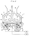
- FIG. 1 shows in schematic vertical cross section a fluidized-bed combustor according to a first embodiment of the present invention.
- the fluidized-bed combustor comprises an incombustible material discharge port 8 disposed centrally in the bottom of a fluidized-bed furnace 1, and a first diffuser plate 2 and a second diffuser plate 3 which are disposed in the fluidized-bed furnace 1 between the incombustible material discharge port 8 and a side wall 42 of the fluidized-bed furnace 1.
- the fluidized-bed combustor further comprises a combustible material supply port 10 disposed above the first diffuser plate 2, an inclined wall 9 disposed above the second diffuser plate 3, and a free board 44 disposed above the inclined wall 9.
- the fluidized-bed furnace 1 may be of a rectangular or circular shape when viewed in plan.
- a main fluidized bed is formed in the fluidized-bed furnace 1 when a fluidized medium composed of incombustible particles such as sand is blown upwardly into a fluidized state by a fluidizing gas such as air that is introduced upwardly into the fluidized-bed furnace 1 from the first diffuser plate 2 and the second diffuser plate 3.
- the main fluidized bed has a varying upper surface 43 positioned somewhere in the height of the inclined wall 9.
- a first diffuser chamber 4 defined below the first diffuser plate 2 is supplied with a fluidizing gas such as air from a gas supply 14 through a pipe 62 and a connector 6.
- the fluidizing gas in the first diffuser chamber 4 is supplied through a number of fluidizing gas supply holes 72 defined in the first diffuser plate 2 into the fluidized-bed furnace 1 at a relatively low fluidizing gas velocity, thus forming a weak fluidized-bed region 17 of the fluidized medium above the first diffuser plate 2.
- the fluidized medium produces a descending flow 18.
- the first diffuser plate 2 has a downwardly inclined upper surface which, in vertical cross section, is progressively lower toward the incombustible material discharge port 8. In FIG. 1, the descending flow 18 is converted into a substantially horizontal flow 19 along the downwardly inclined upper surface of the first diffuser plate 2 in the vicinity of the upper surface of the first diffuser plate 2.
- the second diffuser plate 3 has a number of fluidizing gas supply holes 74 defined therein, and defines a second diffuser chamber 5 therebelow.
- the second diffuser chamber 5 is supplied with a fluidizing gas such as air from a gas supply 15 through a pipe 64 and a connector 7.
- the fluidizing gas in the second diffuser chamber 5 is supplied through the fluidizing gas supply holes 74 into the fluidized-bed furnace 1 at a relatively high fluidizing gas velocity, thus forming an intense fluidized-bed region 16 of the fluidized medium above the second diffuser plate 3.
- the fluidized medium produces an upward flow 20.
- the second diffuser plate 3 has an upwardly inclined upper surface which, in vertical cross section, is lowest near the incombustible material discharge port 8 and progressively higher toward the side wall 42.
- the fluidized medium in the fluidized-bed furnace 1 moves from an upper region of the upward flow 20 into an upper region of the weak fluidized-bed region 17, i.e., an upper region of the descending flow 18, descends with the descending flow 18, and moves from the horizontal flow 19 into a lower region of the upward flow 20, thereby creating a main circulating flow.
- the inclined wall 9 is progressively higher from the side wall 42 toward the center of the fluidized-bed furnace 1 for forcibly directing the upward flow 20 toward a region above the first diffuser plate 2.
- the combustible material supply port 10 which is positioned above the first diffuser plate 2, charges combustible material 38 into a region above the first diffuser plate 2 in the fluidized-bed furnace 1.
- the combustible material 38 supplied from the combustible material supply port 10 is mixed with the descending flow 18 of the fluidized medium, and descends with the descending flow 18 toward the bottom of the fluidized-bed furnace 1 while being thermally decomposed or partially combusted. Then, the combustible material 38 is mixed with the horizontal flow 19 of the fluidized medium along the downwardly inclined upper surface of the first diffuser plate 2, and move horizontally toward the incombustible material discharge port 8.
- the combustible material in the horizontal flow 19 is subjected to a selective action of the upwardly supplied fluidizing gas, and separated into incombustible material 11 of a greater specific gravity in a lower region of the horizontal flow 19 and combustible material of a smaller specific gravity in an upper region of the horizontal flow 19. Therefore, an upper fluidized bed 12 having a high combustible material concentration with a small specific gravity and a lower fluidized bed 13 having a high incombustible material concentration with a large specific gravity are produced in the horizontal flow 19 in the vicinity of the incombustible material discharge port 8.
- the upper fluidized bed 12 flows beyond the incombustible material discharge port 8 and is mixed with the upward flow 20 of the fluidised medium, and the combustible material in the fluidized bed is combusted in an oxidizing atmosphere and intensive fluidization.
- Combustion gases produced in the fluidized bed flow beyond the upper surface 43 of the fluidized bed upwardly into the free board 44 wherein they are subjected to secondary combustion, dust removal, and thermal energy recovery. Thereafter the combustion gases are discharged into the atmosphere.
- the fluidized medium and the incombustible material in the lower fluidized bed 13 are extracted from the incombustible material discharge port 8.
- the fluidized medium and the incombustible material in the lower fluidized bed 13 are discharged out of the fluidized-bed furnace 1 from the incombustible material discharge port 8 through a passage 40, and a hopper, a discharge damper, or the like (not shown) which is connected to the passage 40.
- the fluidized medium that is taken together with the incombustible material out of the fluidized-bed furnace 1 is retrieved by a suitable means (not shown), and returned to the fluidized-bed furnace 1.
- the volume of air to be blown out from the first diffuser plate 2 is controlled in such a manner that the fluidizing gas velocity slows to a velocity of approximately 1 to 2.5 times the minimum fluidizing gas velocity (Umf).
- the volume of air to be blown out from the second diffuser plate 3 is controlled in such a manner that the fluidizing gas velocity achieves a high velocity of approximately 4 to 12 times the minimum fluidizing gas velocity (Umf).
- the fluidizing gas is supplied from the gas supply 15 through the pipe 64, branch pipes 66, and nozzles 21 into the passage 40. From the passage 40, the fluidizing gas is introduced through the incombustible material discharge port 8 upwardly into the fluidized-bed furnace 1, and fluidizes the fluidized medium above the incombustible material discharge port 8 to form a main fluidized bed that is continuous from the region above the first diffuser plate 2 to the region above the second diffuser plate 3 for thereby stabilizing the main circulating flow of the fluidized medium.
- the second diffuser plate 3 which has the upwardly inclined upper surface that is progressively higher away from the incombustible material discharge port 8, gradually converts the upper fluidized bed 12 separated from the horizontal flow which moves substantially horizontally along the downwardly inclined upper surface of the first diffuser plate 2 toward the region above the incombustible material discharge port 8, into the upward flow 20.
- the fluidizing gas velocity of the fluidizing gas supplied from the second diffuser plate 3 may be progressively greater away from the incombustible material discharge port 8 so that the main circulating flow is effectively formed.
- FIG. 2 shows in schematic vertical cross section a fluidized-bed combustor according to a second embodiment of the present invention.
- the fluidized-bed combustor comprises a first diffuser plate 2 disposed centrally on the bottom of a fluidized-bed furnace 1, auxiliary diffuser plates 3' disposed on opposite sides of the first diffuser plate 2 and each having a number of fluidizing gas supply holes 76 defined therein, and incombustible material discharge ports 8 and a second diffuser plate 3 which are disposed between the auxiliary diffuser plates 3' and a side wall 42 of the fluidized-bed furnace 1.
- the fluidized-bed combustor further comprises a combustible material supply port 10 disposed above the first diffuser plate 2, an inclined wall 9 disposed above the second diffuser plate 3, and a free board 44 disposed above the inclined wall 9.
- the first diffuser plate 2 has a downwardly inclined upper surface which, in vertical cross section, is highest at its center and progressively lower toward the incombustible material discharge ports 8. If the fluidized-bed furnace 1 has a circular horizontal cross-sectional shape, then the upper surface of the first diffuser plate 2 is of a conical shape. In FIG. 2, a descending flow 18 of a fluidized medium in the fluidized-bed furnace 1 is divided, in a region near a central crest 73 of the first diffuser plate 2, into two substantially horizontal flows 19 flowing in opposite directions along the downwardly inclined upper surface of the first diffuser plate 2. If the fluidized-bed furnace 1 has a circular horizontal cross-sectional shape, then the second diffuser plate 3 has an inverted conical upper surface which has an outer circumferential edge higher than its inner circumferential edge.
- the first diffuser plate 2 has outer edges joined to the auxiliary diffuser plates 3' having a number of fluidizing gas supply holes 76, below which auxiliary diffuser chambers 5' are defined.
- the auxiliary diffuser chambers 5' are supplied with a fluidizing gas from a gas supply 15 through a pipe 64, branch pipes 68, valves 68', and connectors 7'.
- the fluidizing gas in the auxiliary diffuser chambers 5' is introduced through the fluidizing gas supply holes 76 into the fluidized-bed furnace 1 at a relatively high fluidizing gas velocity, thereby fluidizing a fluidized medium above the auxiliary diffuser plates 3'.
- the volume of air to be blown out from the auxiliary diffuser plate 3' is controlled in such a manner that the fluidizing gas velocity achieves a high velocity of approximately 4 to 12 times the minimum fluidising gas velocity (Umf).
- the fluidized medium in the fluidized-bed furnace 1 moves from upper regions of upward flows 20 into an upper region of a weak fluidized-bed region 17, i.e., an upper region of the descending flow 18, descends with the descending flow 18, and moves from horizontal flows 19 into lower regions of the upward flows 20, thereby creating a main circulating flow.
- the descending flow 18, which is composed of a moving bed, is divided, near the central crest 73 of the first diffuser plate 2, into two substantially horizontal flows 19 flowing in opposite directions along the downwardly inclined upper surface of the first diffuser plate 2. If the fluidized-bed furnace 1 has a rectangular horizontal cross-sectional shape, then two left and right main circulating flows are generated in the fluidized-bed furnace 1.
- the incombustible material such as iron which has a large specific gravity in the horizontal flows 19 is not deposited on the bottom of the fluidized-bed furnace 1, but is moved.
- the moving bed is turned into a moving bed having a large fluidizing speed by the fluidizing gas supplied from the auxiliary diffuser plates 3'. Therefore, the incombustible material of a large specific gravity is rapidly settled down due to the selective action of the fluidizing gas.
- the auxiliary diffuser plate 3' is steeper than the first diffuser plate 2, so that the settled incombustible material of a large specific gravity is moved by gravity along the downwardly inclined surfaces of the auxiliary diffuser plate 3' toward the incombustible material discharge ports 8.
- FIG. 2 The other details of the fluidized-bed combustor shown in FIG. 2 will not be described in detail below because it is substantially the same as the fluidized-bed combustor shown in FIG. 1 except that it has the auxiliary diffuser plates 3' and the auxiliary diffuser chamber 5', and the first diffuser plate 2, the incombustible material discharge ports 8 and the second diffuser plate 3 are symmetrical with respect to the center of the fluidized-bed furnace 1.
- FIG. 3 shows in schematic vertical cross section a fluidized-bed combustor according to a third embodiment of the present invention.
- a fluidized-bed furnace 1 has auxiliary diffuser plates 3' which are steeper than the auxiliary diffuser plates 3' shown in FIG. 2, and have a lower edge 77 lying in vertical alignment with, but vertically spaced from, a lower edge 75 of a second diffuser plate 3 adjacent thereto.
- Each of the incombustible material discharge ports 8 is open laterally through a vertical gap between the lower edge 77 and the lower edge 75.
- a fluidizing gas is not supplied from the incombustible material discharge ports 8, and the incombustible material discharge ports 8 are not open in a horizontal plan and hence do not interrupt upward flows of the fluidizing gas. Therefore, the incombustible material discharge ports 8 do not disturb a main circulating flow of the fluidized medium.
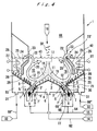
- FIG. 4 shows in schematic vertical cross section a fluidized-bed combustor according to a fourth embodiment of the present invention.
- a fluidized-bed furnace 1 has incombustible material discharge ports 8 which are open laterally through vertical gaps between lower edges 75, 77. A fluidizing gas is not supplied from the incombustible material discharge ports 8.
- the fluidized-bed furnace 1 has a main combustion chamber at the central part thereof and a thermal energy recovery chamber 25 adjacent to the main combustion chamber.
- the thermal energy recovery chamber 25 is defined between an inclined wall 24 above a second diffuser plate 3 and a side wall 42 of the fluidized-bed furnace 1, and houses heat collectors 27.
- the inclined wall 24 has a vertical downward extension.
- the lower edge of the vertical downward extension of the inclined wall 24 is spaced from the third diffuser plate 28 by a vertical gap which serves as a lower communication passage 29 between the main combustion chamber and a lower region of the thermal energy recovery chamber 25.
- a plurality of vertical screen pipes 23 are disposed between an upper edge of the inclined wall 24 and the side wall 42, and define therebetween upper communication passages 23' between the main combustion chamber and an upper region of the thermal energy recovery chamber 25.
- a gas supply 32 is connected to a third diffusion chamber 30 defined below the third diffuser plate 28 through pipes 68'' and connectors 31.
- a fluidizing gas is supplied from the third diffusion chamber 30 through a number of fluidizing gas supply holes 78 defined in the third diffuser plate 28 into the thermal energy recovery chamber 25 at a relatively low fluidizing gas velocity, thereby producing auxiliary circulating flows 26 in which a fluidized medium descends.
- the volume of air to be blown out from the third diffuser plate 28 is controlled in such a manner that the fluidizing gas velocity slows to a velocity of approximately 1 to 2.5 times the minimum fluidizing gas velocity (Umf).
- the reversed flows 22 enter an upper region of the thermal energy recovery chamber 25, in which they descend as descending flows.
- the descending flows pass through the lower communication passage 29, are mixed with the upward flows 20 of main circulating flows, and ascend and reach upper regions of the upward flows 20, thus creating the auxiliary circulating flows 26 of the fluidized medium which pass through the thermal energy recovery chamber 25.
- the fluidized medium in the auxiliary circulating flows 26 is cooled by a heat exchange carried out by the heat collectors 27 in the thermal energy recovery chamber 25, and then heated by the heat of combustion in the upward flows 20. Since the overall heat-transfer coefficient of the heat collectors 27 varies greatly depending on the fluidizing gas velocity as shown in FIG. 10, the amount of collected thermal energy can effectively be controlled by varying the amount of the fluidizing gas which passes through the third diffuser plate 28.
- the fluidizing gas is supplied from the incombustible material discharge port 8, and the main fluidized bed is free of interrupted regions, so that a stable main circulating flow is generated.
- the lower edges of the auxiliary diffuser plates 3' are vertically spaced from the lower edge of the adjacent second diffuser plate 3 so as to define the incombustible material discharge port 8 in the vertical gap between the spaced lower edges.
- the flow of the fluidizing gas supplied upwardly from the bottom of the fluidized-bed furnace is free of interrupted regions, and hence a stable fluidized bed is created in the same manner as the fluidized-bed combustor shown in FIGS. 1 and 2.
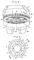
- FIGS. 5, 6, and 7 are perspective, plan, and cross-sectional views, respectively, of the circular bottom of a fluidized-bed combustor according to a fifth embodiment of the present invention.
- the fluidized-bed combustor according to the fifth embodiment corresponds to the fluidized-bed combustor shown in FIG. 2 where the fluidized-bed furnace is of a circular shape as viewed in plan.
- the cross-sectional view shown in FIG. 7 is taken along line VII - VII of FIG. 6.
- a first diffuser plate 2 has a conical surface with its center being higher than its circumferential edge.
- annular auxiliary air diffusion plate 3' An annular auxiliary air diffusion plate 3', four arcuate incombustible material discharge ports 8, and a second diffuser plate 3 are disposed concentrically around the first diffuser plate 2.
- the annular auxiliary air diffusion plate 3' has an inclined surface steeper than the inclined surface of the central first diffuser plate 2.
- the second diffuser plate 3 has an annular inverted conical surface with its inner circumferential edge being lower than its outer circumferential edge.
- a second diffuser chamber 5 defined below the second diffuser plate 3 is of an annular shape.
- each of the fourth diffuser plates 3'' has two downwardly inclined surfaces directed toward the two incombustible material discharge ports 8 that are positioned one on each side thereof.
- the volume of air to be blown out from the fourth diffuser plate 3'' is controlled in such a manner that the fluidizing gas velocity achieves a high velocity of approximately 4 to 12 times the minimum fluidizing gas velocity (Umf).
- each of the fourth diffuser plates 3'' serve to guide incombustible material having a large specific gravity toward the incombustible material discharge ports 8, thereby preventing those incombustible material from being deposited on the fourth diffuser plates 3''.
- the other structural details and functions of the fluidized-bed combustor according to the fifth embodiment are substantially the same as those of the fluidized-bed combustor according to the second embodiment shown in FIG. 2, and will not be described in detail.
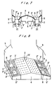
- FIG. 8 shows in perspective view the bottom of a fluidized-bed furnace of a fluidized-bed combustor according to a sixth embodiment of the present invention.
- the fluidized-bed combustor according to the sixth embodiment corresponds to the fluidized-bed combustor shown in FIG. 2 where the fluidized-bed furnace is of a rectangular shape as viewed in plan.
- a first diffuser plate 2 is of a rectangular shape as viewed in plan, and has a roof-shaped structure with a central ridge 73'.
- the first diffuser plate 2, auxiliary air diffusion plates 3', incombustible material discharge ports 8, and second diffuser plates 3 are disposed symmetrically with respect to the central ridge 73', and are rectangular in shape.
- the fluidized-bed combustor shown in FIG. 8 includes fourth diffuser plates 3'' extending perpendicularly to the ridge 73' and along edges of the incombustible material discharge ports 8, and having downwardly inclined surfaces directed toward the incombustible material discharge ports 8.
- the downwardly inclined surfaces of the fourth diffuser plates 3'' serve to guide incombustible material having a large specific gravity toward the incombustible material discharge ports 8, thereby preventing the incombustible material from being deposited on the fourth diffuser plates 3''.
- the other structural details and functions of the fluidized-bed combustor according to the sixth embodiment are substantially the same as those of the fluidized-bed combustor according to the second embodiment shown in FIG. 2, and will not be described in detail.
- FIG. 9 shows in perspective view the bottom of a fluidized-bed furnace of a fluidized-bed combustor according to a seventh embodiment of the present invention.
- the fluidized-bed combustor according to the seventh embodiment corresponds to the fluidized-bed combustor shown in FIG. 2 where the fluidized-bed furnace is of a rectangular shape as viewed in plan, and is essentially similar to the fluidized-bed combustor according to the sixth embodiment shown in FIG. 8.
- second diffuser plates 3 have edges located adjacent to incombustible material discharge ports 8 and lying in the planes of extensions of inclined surfaces of a first diffuser plate 2, and also have edges located adjacent to a side wall of the fluidized-bed furnace and lying above the planes of the extensions of the inclined surfaces of the first diffuser plate 2.
- the other structural details and functions of the fluidized-bed combustor according to the seventh embodiment are substantially the same as those of the fluidized-bed combustor according to the second and sixth embodiments shown in FIGS. 2 and 8, and will not be described in detail.
- fluidized-bed combustor according to the sixth and seventh embodiments shown in FIGS. 8 and 9 have fewer curved surfaces than the fluidized-bed combustor according to the other embodiments, they can be designed and machined relatively easily, and can be manufactured relatively inexpensively.
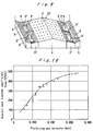
- FIG. 10 is a graph showing the relationship between the overall heat-transfer coefficient of the heat collector and the fluidizing gas velocity of a fluidizing gas supplied from the third diffuser plate 28 in the fluidized-bed combustor according to the present invention.
- the overall heat-transfer coefficient of the heat collector varies greatly depending on the fluidizing gas velocity in a fluidizing gas velocity range from 0 to 0.3 m/s, particularly from 0.05 to 0.25 m/s. Therefore, when the fluidizing gas velocity in the thermal energy recovery chamber is adjusted in the above range, the overall heat-transfer coefficient of the heat collector can be varied to control the amount of collected thermal energy in a wide range.
Abstract
Description
- The present invention relates to a fluidized-bed combustor for combusting solid combustible material containing incombustible material, e.g., industrial waste, municipal garbage, coal, etc. in a fluidized-bed furnace, and more particularly to a fluidized-bed combustor for discharging incombustible material smoothly from a fluidized-bed furnace to avoid a deposit of incombustible material in a certain location in the fluidized-bed furnace and uniformly combusting solid combustible material to recover thermal energy stably therefrom.
- As economy develops, more and more solid combustible material containing incombustible material, e.g., industrial waste, municipal garbage, etc. is produced as a result of various human activities. This solid combustible material contains a large amount of energy that can be used. However, it is difficult to combust the solid combustible material stably to utilize its energy because the solid combustible material is available in a wide variety of natures and configurations and contains a large quantity of incombustible material of indeterminate shape mixed therewith.
- Japanese laid-open patent publication (JP-A) No. 4-214110 discloses a fluidized-bed combustor which combusts waste material containing incombustible material in a fluidized-bed furnace, and discharges the incombustible material smoothly from the fluidized-bed furnace to allow the waste material to be combusted stably in the fluidized-bed furnace. In the disclosed fluidized-bed combustor shown in FIG. 1 of this publication, an incombustible material discharge port 50 is defined between an
air diffuser plate 40 and a furnace wall, and theair diffuser plate 40 has an inclinedupper surface 44 inclined such that the incombustible material discharge port 50 is located in a lower position. Theair diffuser plate 40 supplies more air to a lower region of theair diffuser plate 40 than to a higher region of theair diffuser plate 40. However, since a fluidized medium is intensely fluidized in the lower region of theair diffuser plate 40 by a large amount of air supplied thereto, a fluidized bed has a characteristic similar to liquid. Therefore, material of larger specific gravity than the fluidized medium descends in the fluidized bed, and material of smaller specific gravity than the fluidized medium floats in the fluidized bed, thus creating so-called specific gravity separation. As a result, incombustible material of a large specific gravity descends in the fluidized bed, and deposited on the bottom of the furnace before reaching the incombustible material discharge port 50. Further, since the incombustible material discharge port 50 to which a fluidizing gas is not supplied is open in the bottom of the furnace, the fluidized bed above the incombustible material discharge port 50 is not stabilized. - A fluidized-bed combustor shown in FIG. 11 of the above publication (No. 4-214110) has air diffuser plates 90a, 90b having respective downwardly inclined surfaces which extend from the center of a fluidized-bed furnace toward two incombustible material discharge ports 95a, 95b, and air diffuser plates 90c, 90d having respective downwardly inclined surfaces which extend from a furnace side wall toward the incombustible material discharge ports 95a, 95b. While more air is supplied from the regions of the air diffuser plate next to those incombustible material discharge ports through air chambers 93c, 93e than from other regions, a fluidized bed in which a fluidized medium is intensely fluidized by a large amount of air supplied thereto has a characteristic similar to liquid. Therefore, material of larger specific gravity than the fluidized medium descends in the fluidized bed, and material of smaller specific gravity than the fluidized medium floats in the fluidized bed, thus creating so-called specific gravity separation. As a result, incombustible material of a large specific gravity descends in the fluidized bed, and deposited on the bottom of the furnace before reaching the incombustible material discharge ports 95a, 95b. Thus, the incombustible material cannot be discharged smoothly, and fluidization of the fluidized medium is not carried out smoothly, resulting in malfunction of the furnace. Further, since the incombustible material discharge ports in which a fluidizing gas is not introduced are open in the bottom of the furnace as viewed in plan, a fixed bed in which the fluidized medium is not fluidized is formed at the region near or above the incombustible material discharge ports. Therefore, the fixed bed prevents a circulating flow in the fluidized bed from being formed, dispersion and mixture of combustible material in the fluidized bed are not effectively carried out, and incombustible material cannot be smoothly discharged out of the furnace.
- Japanese patent publication (JP-B2) No. 5-19044 discloses a fluidized-bed furnace for incinerating waste material containing incombustible material such as metal pieces, soil, and rocks. The disclosed fluidized-bed furnace has a furnace bed including downwardly inclined surfaces extending toward an incombustible
material discharge port 5 disposed centrally in the furnace bed. Fluidizing air is supplied such that the amount of fluidizing air per unit area of the furnace bed is larger in the vicinity of the incombustible material discharge port and decreases stepwise toward a furnace side wall. Therefore, a circulating flow of the fluidized medium which ascends at the region near the incombustiblematerial discharge port 5 located at the central part of the furnace and descends in the vicinity of the side wall of the furnace is formed, but combustible waste is supplied from a supply port located above the incombustiblematerial discharge port 5, thus the combustible waste is blown up by an upward flow and combusted on the fluidized bed or in the free board, resulting in lowering combustion efficiency in the fluidized bed. - In order to prevent the above disadvantages, in case of supplying the combustible waste from the side wall of the furnace, dispersion and mixture of the combustible waste in the fluidized bed are improved because the combustible waste is entrained by the descending flow. However, since a large amount of air is supplied to the region near the incombustible
material discharge port 5, the fluidized bed in which the fluidized medium is intensely fluidized in such region has a characteristic similar to liquid as in the fluidized-bed furnace of JP-A-4-214110. Therefore, material of larger specific gravity than the fluidized medium descends in the fluidized bed, and material of smaller specific gravity than the fluidized medium floats in the fluidized bed, thus creating specific gravity separation. As a result, incombustible material of a large specific gravity descends in the fluidized bed, deposited on the bottom of the furnace before reaching the incombustible material discharge port, and cannot be smoothly discharged out of the furnace. - It is therefore a general object of the present invention to provide a fluidized-bed combustor for combusting solid combustible material containing incombustible material, e.g., industrial waste, municipal garbage, coal, etc. in a fluidized-bed furnace, the fluidized-bed combustor being capable of removing incombustible material of a large specific gravity smoothly from the fluidized-bed furnace to prevent those incombustible material from being deposited in a certain location in the fluidized-bed furnace for thereby stabilizing fluidization in the fluidized-bed furnace and uniformly combusting the combustible material.
- Incombustible material of a large specific gravity, such as iron or the like, is less susceptible to descending and capable of moving horizontally when supported by a moving bed (the transient state of a fluidized medium between a fixed bed and a fluidized bed), but is quickly settled down and deposited and cannot easily be moved in a fluidized bed in which the fluidized medium is violently fluidized. Thus, it is difficult to discharge the incombustible material out of the furnace.
- In view of the above fact, it is a specific object of the present invention to provide a fluidized-bed combustor which is capable of moving combustible material containing incombustible material supplied into a fluidized-bed furnace to a position in the vicinity of an incombustible material discharge port with a fluidized medium, violently fluidizing the fluidized medium and rapidly combusting the combustible material in the vicinity of the incombustible material discharge port, and settling and separating incombustible material of a large specific gravity to discharge it from the incombustible material discharge port.
- Another object of the present invention is to provide a fluidized-bed combustor in which the flow of a fluidizing gas is not interrupted by an incombustible material discharge port to thereby stabilize a main fluidized bed and a main circulating flow of a fluidized medium which are produced in a fluidized-bed furnace for combusting combustible material effectively.
- Still another object of the present invention is to provide a fluidized-bed combustor in which while combustible material containing incombustible material supplied into a fluidized-bed furnace is moving in descending and horizontal flows of a fluidized medium, the combustible material is separated by a selective action of a fluidizing gas into an upper fluidized bed having a high combustible material concentration with a small specific gravity and a lower fluidized bed having a high incombustible material concentration with a large specific gravity, the upper fluidized bed flows beyond an incombustible material discharge port and is mixed with an upward flow for further circulation, and the incombustible material and fluidized medium in the lower fluidized bed are extracted with priority out of the fluidized-bed furnace through the incombustible material discharge port.
- Yet still another object of the present invention is to provide a fluidized-bed combustor which is capable of effectively discharging incombustible material out of a fluidized-bed furnace, and has a heat collector disposed in an auxiliary fluidized bed that is produced separately from a main fluidized bed, for stably recovering thermal energy.
- According to the present invention, there is provided a fluidized-bed combustor for combusting combustible material containing incombustible material in a fluidized-bed furnace, comprising: a first diffuser plate disposed at a bottom of the fluidized-bed furnace and having a plurality of holes for supplying a fluidizing gas with a relatively low fluidizing gas velocity; a second diffuser plate disposed at a bottom of the fluidized-bed furnace and having a plurality of holes for supplying a fluidizing gas with a relatively high fluidizing gas velocity; an incombustible material discharge port for discharging the incombustible material out of the fluidized-bed furnace, the incombustible material discharge port being defined between the first diffuser plate and the second diffuser plate; a combustible material supply port disposed above the first diffuser plate for supplying the combustible material into the fluidized-bed furnace; and a diffuser device for supplying a fluidizing gas through the incombustible material discharge port into the fluidized-bed furnace; wherein the first diffuser plate has a downwardly inclined surface directed to the incombustible material discharge port and supplies the fluidizing gas so as to fluidize a fluidized medium at a relatively low fluidizing speed and create a descending flow of the fluidized medium; and the second diffuser plate supplies the fluidizing gas so as to fluidize the fluidized medium at a relatively high fluidizing speed and create an upward flow of the fluidized medium.
- The fluidized medium forms a main circulating flow which includes descending and upward flows. A fluidizing gas is supplied from the incombustible material discharge port to continue a main fluidized bed in the vicinity of the incombustible material discharge port for thereby stabilizing the main circulating flow.
- While combustible material containing incombustible material supplied from the combustible material supply port into the fluidized-bed furnace is descending with the descending flow of the fluidized medium toward the bottom of the fluidized-bed furnace and horizontally moving along the downwardly inclined surface of the first diffuser plate, the combustible material is separated by a selective action of an upwardly supplied fluidizing gas into an upper fluidized bed having a high combustible material concentration with a small specific gravity and a lower fluidized bed having a high incombustible material concentration with a large specific gravity. The upper fluidized bed flows beyond the incombustible material discharge port and is mixed with the upward flow of the moving fluidized medium for further circulation and combustion. The incombustible material and the fluidized medium in the lower fluidized bed are extracted with priority out of the fluidized-bed furnace through the incombustible material discharge port.
- Preferably, the fluidized-bed combustor further comprises an auxiliary diffuser plate disposed between the first diffuser plate and the incombustible material discharge port, the auxiliary diffuser plate having a plurality of fluidizing gas supply holes defined therein for supplying a fluidizing gas so as to fluidize the fluidized medium at a relatively high fluidizing speed, the auxiliary diffuser plate having a downwardly inclined surface extending between a lower edge of the first diffuser plate and the incombustible material discharge port and being steeper than the first diffuser plate. The fluidized-bed furnace has an inclined wall disposed above the second diffuser plate for directing the fluidizing gas and the fluidized medium flowing upwardly of the second diffuser plate toward a region above the first diffuser plate, i.e., a central region of the fluidized-bed furnace. A free board is disposed above the inclined wall. The second diffuser plate has an upwardly inclined surface which is progressively higher away from the incombustible material discharge port and supplies the fluidizing gas having a progressively increasing fluidizing gas velocity away from the incombustible material discharge port.
- The fluidized-bed combustor also comprises a thermal energy recovery chamber defined between the inclined wall and a side wall of the fluidized-bed furnace and being in communication with the central region of the fluidized-bed furnace above and below the inclined wall; a heat collector disposed in the thermal energy recovery chamber for recovering thermal energy from the fluidized medium in the thermal energy recovery chamber; and a third diffuser plate disposed between the second diffuser plate and the side wall of the fluidized-bed furnace and extending contiguously to an outer edge of the second diffuser plate, the third diffuser plate having a plurality of holes for supplying a fluidizing gas with a relatively low fluidizing gas velocity; wherein the third diffuser plate has an upwardly inclined surface which has the same gradient as the second diffuser plate and supplies the fluidizing gas to fluidize the fluidized medium at a relatively low fluidizing speed in the thermal energy recovery chamber.
- The bottom of the fluidized-bed furnace may be of a rectangular or circular shape. If the bottom of the fluidized-bed furnace is of a rectangular shape, then the first diffuser plate, the incombustible discharge port, and the second diffuser plate, which are of a rectangular shape, may be disposed parallel to each other, or alternatively, the incombustible material discharge port and the second diffuser plate, which are of a rectangular shape, may be disposed symmetrically with respect to a ridge of the first diffuser plate which is of a rectangular, roof-shaped structure. If the bottom of the fluidized-bed furnace is of a circular shape, then the circular bottom of the fluidized-bed furnace is composed of the first diffuser plate which is of a conical shape having a central region higher than a circumferential edge thereof, the incombustible material discharge port comprising a plurality of arcuate sections disposed concentrically with the first diffuser plate, and the second diffuser plate which is of an annular shape disposed concentrically with the first diffuser plate.
- According to the present invention, there is also provided a fluidized-bed combustor for combusting combustible material containing incombustible material in a fluidized-bed furnace, comprising: a first diffuser plate disposed at a bottom of the fluidized-bed furnace and having a plurality of holes for supplying a fluidizing gas with a relatively low fluidizing gas velocity; an auxiliary diffuser plate disposed at a bottom of the fluidized-bed furnace and having a plurality of holes for supplying a fluidizing gas with a relatively high fluidizing gas velocity; a second diffuser plate disposed at a bottom of the fluidized-bed furnace and having a plurality of holes for supplying a fluidizing gas with a relatively high fluidizing gas velocity; an incombustible material discharge port for discharging the incombustible material out of the fluidized-bed furnace, the incombustible material discharge port being defined between the auxiliary diffuser plate and the second diffuser plate; and a combustible material supply port disposed above the first diffuser plate for supplying the combustible material into the fluidized-bed furnace; wherein the first diffuser plate has a downwardly inclined surface directed to the incombustible material discharge port and supplies the fluidizing gas so as to fluidize a fluidized medium at a relatively low fluidizing speed and create a descending flow of the fluidized medium; the auxiliary diffuser plate has a downwardly inclined surface extending between a lower edge of the first diffuser plate and the incombustible material discharge port and directed to the incombustible material discharge port and supplies the fluidizing gas so as to fluidize the fluidized medium at a relatively high fluidizing speed, and the downwardly inclined surface of the auxiliary diffuser plate being steeper than the downwardly inclined surface of the first diffuser plate and having a lower edge substantially vertically aligned with and vertically spaced from an adjacent edge of the second diffuser plate, the incombustible material discharge port being open in a vertical gap between the lower edge of the downwardly inclined surface of the auxiliary diffuser plate and the adjacent edge of the second diffuser plate; and the second diffuser plate supplies the fluidizing gas so as to fluidize the fluidized medium at a relatively high fluidizing speed and create an upward flow of the fluidized medium.
- Preferably, the fluidized-bed furnace has an inclined wall disposed above the second diffuser plate for directing the fluidizing gas and the fluidized medium flowing upwardly of the second diffuser plate toward a region above the first diffuser plate, i.e., a central region of the fluidized-bed furnace. A free board is disposed above the inclined wall. The second diffuser plate has an upwardly inclined surface which is progressively higher away from the incombustible material discharge port and supplies the fluidizing gas having a progressively increasing fluidizing gas velocity away from the incombustible material discharge port. The fluidized-bed combustor also has a thermal energy recovery chamber defined between the inclined wall and a side wall of the fluidized-bed furnace and being in communication with the central region of the fluidized-bed furnace above and below the inclined wall; a heat collector disposed in the thermal energy recovery chamber for recovering thermal energy from the fluidized medium in the thermal energy recovery chamber; and a third diffuser plate disposed between the second diffuser plate and the side wall of the fluidized-bed furnace and extending contiguously to an outer edge of the second diffuser plate, the third diffuser plate having a plurality of holes for supplying a fluidizing gas with a relatively low fluidizing gas velocity; wherein the third diffuser plate has an upwardly inclined surface which has the same gradient as the second diffuser plate and supplies the fluidizing gas to fluidize the fluidized medium at a relatively low fluidizing speed in the thermal energy recovery chamber. The bottom of the fluidized-bed furnace may be of a rectangular or circular shape. If the bottom of the fluidized-bed furnace is of a rectangular shape, then the first diffuser plate, and the second diffuser plate, which are of a rectangular shape, may be disposed parallel to each other, or alternatively, the first diffuser plate and the second diffuser plate, which are of a rectangular shape, may be disposed symmetrically with respect to a ridge of the first diffuser plate which is of a rectangular, roof-shaped structure. If the bottom of the fluidized-bed furnace is of a circular shape, then the circular bottom of the fluidized-bed furnace is composed of the first diffuser plate which is of a conical shape, the second diffuser plate which is of an inverted conical shape disposed concentrically with the first diffuser plate, and the incombustible material discharge port which is open in the vertical gap between the outer circumferential edge of the first diffuser plate and the inner circumferential edge of the second diffuser plate.
- In the fluidized-bed combustor, a fluidizing gas such as air supplied from the first diffuser plate fluidizes a fluidized medium at a relatively low fluidizing speed to create a descending flow of the fluidized medium, and a fluidizing gas such as air supplied from the second diffuser plate fluidizes the fluidized medium at a relatively high fluidizing speed to create an upward flow of the fluidized medium, thus producing a main circulating fluidized bed including the descending and upward flows. After the fluidized medium descends with the descending flow, it is guided by the downwardly inclined surface of the first diffuser plate, and ascends with the upward flow in the vicinity of the second diffuser plate. Having reached an upper region of the fluidized bed, the fluidized medium is directed to the central region of the fluidized-bed furnace, and then descends with the descending flow again, with the result that a main circulating flow is generated which circulates in the main fluidized bed.
- By supplying the fluidizing gas so as to fluidize the fluidized medium at a relatively large fluidizing speed from the diffuser device provided on the inner surface of the incombustible material discharge port, the fluidized medium in the region near or above the incombustible material discharge port is fluidized intensely. As a result, not a fixed bed but a fluidized bed is formed above the incombustible material discharge port, a fluidized region of the fluidized medium continues from the first diffuser plate to the second diffuser plate, and a circulating flow including a descending flow in the weak fluidized region and an upward flow in the intense fluidized region is stably formed without interrupted. The inclined wall above the second diffuser plate directs the fluidizing gas and the fluidized medium ascending upwardly of the second diffuser plate toward the central region of the fluidized-bed furnace, thereby promoting the formation of the main circulating flow.
- Next, separation of incombustible material from combustible material will be described in detail. Combustible material containing incombustible material is supplied to a location above the first diffuser plate from the combustible material supply port. The fluidized medium above the first diffuser plate is slowly fluidized, and a moving bed of an intermediate state between a fixed bed and a fluidized bed is formed. Since the combustible material and the incombustible material is suspended in the fluidized medium of the moving bed, they descend together with the circulating flow in the fluidized bed, and then move horizontally toward a fluidized region above the second diffuser plate which supplies a fluidizing gas with a relatively large fluidizing gas velocity. Even though the combustible material and the incombustible material are suspended in the fluidized medium above the first diffuser plate, the fluidized medium is slowly fluidized, and material of larger specific gravity than the bulk density of the moving bed descends gradually and material of smaller specific gravity than the bulk density of the moving bed floats during the horizontal flow of the fluidized medium, thus creating specific gravity separation. As a result, the combustible material of a small specific gravity moves toward an upper region of the horizontal flow and the incombustible material of a large specific gravity moves toward a lower region of the horizontal flow. Therefore, an upper fluidized bed having a high combustible material concentration with a small specific gravity and a lower fluidized bed having a high incombustible material concentration with a large specific gravity are produced from the combustible material in the horizontal flow in the vicinity of the incombustible material discharge port.
- The upper fluidized bed flows beyond the incombustible material discharge port and is mixed with the upward flow of the fluidized medium, and the combustible material in the fluidized bed is combusted in an oxidizing atmosphere and intensive fluidization. Since the upper fluidized bed has a relatively low incombustible material concentration, the combustible material in the fluidized bed is effectively combusted in the upward flow of the fluidized medium.
- The lower fluidised bed having a large incombustible material concentration with a large specific gravity is guided by the downwardly inclined upper surface of the first diffuser plate toward the incombustible material discharge port, and a part of the fluidized medium and the incombustible material in the lower fluidized bed are extracted from the incombustible material discharge port. Since the fluidized medium above the first diffuser plate is in the state of a moving bed, the incombustible material of a large specific gravity, such as iron or the like is supported by the moving bed, moved toward the incombustible material discharge port, and is not deposited on the bottom of the fluidized-bed furnace.
- On the other hand, by supplying the fluidizing gas so as to fluidize the fluidized medium at a relatively large fluidizing speed from the diffuser device provided on the inner surface of the incombustible material discharge port, the fluidized medium is fluidized intensely at the region near or above the incombustible material discharge port. As a result, not a fixed bed or a moving bed but an intense fluidized bed is formed at the region near or above the incombustible material discharge port, and the fluidized bed has a characteristic similar to liquid. Therefore, material of larger specific gravity than the bulk density of the fluidized bed descends and material of smaller specific gravity floats in the fluidized bed, thus creating specific gravity separation easily. Therefore, the incombustible material of a large specific gravity descends rapidly toward the inside of the incombustible material discharge port, can be easily and smoothly discharged out of the furnace. Since the incombustible material in the fluidized-bed furnace is taken out smoothly and effectively, combustion of the combustible material and formation of the fluidized bed are not prevented. The combustible material and the incombustible material are separated by the selective action of the fluidizing gas, almost all of the incombustible material is effectively taken out, and only a little amount of the fluidized medium is taken out. Therefore, loss of heat is small and the removed incombustible material can easily be processed as any combustible material contained therein is small.
- The auxiliary diffuser plate has a downwardly inclined surface steeper than the downwardly inclined surface of the first diffuser plate and supplies a fluidizing gas so as to fluidize the fluidized medium at a relatively high fluidizing speed. Therefore, since the moving bed above the first diffuser plate is converted into the fluidized bed above the auxiliary diffuser plate, the selective action for the incombustible material is rapidly performed, and the incombustible material of a large specific gravity such as iron descends rapidly onto the auxiliary diffuser plate. However, since the auxiliary diffuser plate has the steeply downwardly inclined surface, the incombustible material of a large specific gravity is smoothly guided toward the incombustible material discharge port. The second diffuser plate has an upwardly inclined surface which is higher away from the incombustible material discharge port and supplies the fluidized gas having a progressively increasing fluidizing gas velocity away from the incombustible material discharge port, thereby promoting the formation of the main circulating flow.
- The third diffuser plate supplies a fluidizing gas so as to fluidize the fluidized medium in the thermal energy recovery chamber at a relatively low fluidizing speed and create a moving bed which moves downwardly in the thermal energy recovery chamber.
- A part of the fluidized medium from the upper region of the upward flow is introduced into the thermal energy recovery chamber beyond an upper end of the inclined wall. In the thermal energy recovery chamber the fluidized medium descends as a moving bed and is cooled by a heat exchange carried out by the heat collector in the thermal energy recovery chamber. Thereafter, the fluidized medium is guided along the third diffuser plate toward the second diffuser plate, where it is mixed with the upward flow and heated by the heat of combustion in the upward flow. In this manner, an auxiliary circulating flow of the fluidized medium is formed by the descending flow in the thermal energy recovery chamber and the upward flow in the main combustion chamber, and the heat of combustion in the fluidized-bed furnace is collected by the heat collector in the thermal energy recovery chamber. Since the overall heat-transfer coefficient of the heat collector varies greatly depending on the fluidizing gas velocity as shown in FIG. 10 of the accompanying drawings, the amount of collected thermal energy can easily be controlled by varying the amount of the fluidizing gas which passes through the third diffuser plate.
- In the case where the fluidized-bed furnace is of a rectangular shape as viewed in plan, it can be designed and manufactured relatively easily. However, in the case where the fluidized-bed furnace is of a circular shape as viewed in plan, the pressure resistance of the side wall of the fluidized-bed furnace can be increased. Therefore, it is possible to keep a low pressure lower than the atmospheric pressure in the fluidized-bed furnace for preventing odors and harmful gases produced upon combustion of waste material from leaking out of the fluidized-bed furnace, or alternatively to keep a high pressure in the fluidized-bed furnace for producing a high-pressure combustion gas capable of operating a gas turbine.
- According to another aspect of the present invention, one of the diffuser plates adjacent to the incombustible material discharge port has a lower edge substantially vertically aligned with and vertically spaced from an adjacent edge of the other of the diffuser plates as viewed in plan, and the incombustible material discharge port is open in a vertical gap between the edges of the diffuser plates. Therefore, the fluidized medium can be fluidized at the region above the incombustible material discharge port without the diffuser device provided on the inner surface of the incombustible material discharge port. As a result, a fluidized region of the fluidized medium continues from the first diffuser plate to the second diffuser plate, and a circulating flow including a descending flow in the weak fluidized region and an upward flow in the intense fluidized region is stably formed without interrupted.
- The above and other objects, features, and advantages of the present invention will become apparent from the following description when taken in conjunction with the accompanying drawings which illustrate preferred embodiments of the present invention by way of example.
-
- FIG. 1 is a schematic vertical cross-sectional view of a fluidized-bed combustor according to a first embodiment of the present invention;
- FIG. 2 is a schematic vertical cross-sectional view of a fluidized-bed combustor according to a second embodiment of the present invention;
- FIG. 3 is a schematic vertical cross-sectional view of a fluidized-bed combustor according to a third embodiment of the present invention;
- FIG. 4 is a schematic vertical cross-sectional view of a fluidized-bed combustor according to a fourth embodiment of the present invention;
- FIG. 5 is a perspective view of the bottom of a fluidized-bed combustor according to a fifth embodiment of the present invention;
- FIG. 6 is a plan view of the bottom of the fluidized-bed combustor shown in FIG. 5;
- FIG. 7 is a cross-sectional view taken along line VII - VII of FIG. 6;
- FIG. 8 is a perspective view of the bottom of a fluidized-bed combustor according to a sixth embodiment of the present invention;
- FIG. 9 is a perspective view of the bottom of a fluidized-bed combustor according to a seventh embodiment of the present invention; and
- FIG. 10 is a graph showing the relationship between the overall heat-transfer coefficient of a heat collector and the fluidizing gas velocity supplied from a third diffuser plate in the fluidized-bed combustor according to the present invention.
- Like or corresponding parts are denoted by like or corresponding reference numerals throughout views.
- FIG. 1 shows in schematic vertical cross section a fluidized-bed combustor according to a first embodiment of the present invention.
- As shown in FIG. 1, the fluidized-bed combustor according to the first embodiment comprises an incombustible
material discharge port 8 disposed centrally in the bottom of a fluidized-bed furnace 1, and afirst diffuser plate 2 and asecond diffuser plate 3 which are disposed in the fluidized-bed furnace 1 between the incombustiblematerial discharge port 8 and aside wall 42 of the fluidized-bed furnace 1. The fluidized-bed combustor further comprises a combustiblematerial supply port 10 disposed above thefirst diffuser plate 2, aninclined wall 9 disposed above thesecond diffuser plate 3, and afree board 44 disposed above theinclined wall 9. The fluidized-bed furnace 1 may be of a rectangular or circular shape when viewed in plan. A main fluidized bed is formed in the fluidized-bed furnace 1 when a fluidized medium composed of incombustible particles such as sand is blown upwardly into a fluidized state by a fluidizing gas such as air that is introduced upwardly into the fluidized-bed furnace 1 from thefirst diffuser plate 2 and thesecond diffuser plate 3. The main fluidized bed has a varyingupper surface 43 positioned somewhere in the height of theinclined wall 9. - A
first diffuser chamber 4 defined below thefirst diffuser plate 2 is supplied with a fluidizing gas such as air from agas supply 14 through apipe 62 and aconnector 6. The fluidizing gas in thefirst diffuser chamber 4 is supplied through a number of fluidizing gas supply holes 72 defined in thefirst diffuser plate 2 into the fluidized-bed furnace 1 at a relatively low fluidizing gas velocity, thus forming a weak fluidized-bed region 17 of the fluidized medium above thefirst diffuser plate 2. In the weak fluidized-bed region 17, the fluidized medium produces a descendingflow 18. Thefirst diffuser plate 2 has a downwardly inclined upper surface which, in vertical cross section, is progressively lower toward the incombustiblematerial discharge port 8. In FIG. 1, the descendingflow 18 is converted into a substantiallyhorizontal flow 19 along the downwardly inclined upper surface of thefirst diffuser plate 2 in the vicinity of the upper surface of thefirst diffuser plate 2. - The
second diffuser plate 3 has a number of fluidizing gas supply holes 74 defined therein, and defines asecond diffuser chamber 5 therebelow. Thesecond diffuser chamber 5 is supplied with a fluidizing gas such as air from agas supply 15 through apipe 64 and aconnector 7. The fluidizing gas in thesecond diffuser chamber 5 is supplied through the fluidizing gas supply holes 74 into the fluidized-bed furnace 1 at a relatively high fluidizing gas velocity, thus forming an intense fluidized-bed region 16 of the fluidized medium above thesecond diffuser plate 3. In the intense fluidized-bed region 16, the fluidized medium produces anupward flow 20. Thesecond diffuser plate 3 has an upwardly inclined upper surface which, in vertical cross section, is lowest near the incombustiblematerial discharge port 8 and progressively higher toward theside wall 42. - The fluidized medium in the fluidized-
bed furnace 1 moves from an upper region of theupward flow 20 into an upper region of the weak fluidized-bed region 17, i.e., an upper region of the descendingflow 18, descends with the descendingflow 18, and moves from thehorizontal flow 19 into a lower region of theupward flow 20, thereby creating a main circulating flow. Theinclined wall 9 is progressively higher from theside wall 42 toward the center of the fluidized-bed furnace 1 for forcibly directing theupward flow 20 toward a region above thefirst diffuser plate 2. - The combustible
material supply port 10, which is positioned above thefirst diffuser plate 2, chargescombustible material 38 into a region above thefirst diffuser plate 2 in the fluidized-bed furnace 1. Thecombustible material 38 supplied from the combustiblematerial supply port 10 is mixed with the descendingflow 18 of the fluidized medium, and descends with the descendingflow 18 toward the bottom of the fluidized-bed furnace 1 while being thermally decomposed or partially combusted. Then, thecombustible material 38 is mixed with thehorizontal flow 19 of the fluidized medium along the downwardly inclined upper surface of thefirst diffuser plate 2, and move horizontally toward the incombustiblematerial discharge port 8. The combustible material in thehorizontal flow 19 is subjected to a selective action of the upwardly supplied fluidizing gas, and separated intoincombustible material 11 of a greater specific gravity in a lower region of thehorizontal flow 19 and combustible material of a smaller specific gravity in an upper region of thehorizontal flow 19. Therefore, an upperfluidized bed 12 having a high combustible material concentration with a small specific gravity and a lowerfluidized bed 13 having a high incombustible material concentration with a large specific gravity are produced in thehorizontal flow 19 in the vicinity of the incombustiblematerial discharge port 8. - The upper
fluidized bed 12 flows beyond the incombustiblematerial discharge port 8 and is mixed with theupward flow 20 of the fluidised medium, and the combustible material in the fluidized bed is combusted in an oxidizing atmosphere and intensive fluidization. Combustion gases produced in the fluidized bed flow beyond theupper surface 43 of the fluidized bed upwardly into thefree board 44 wherein they are subjected to secondary combustion, dust removal, and thermal energy recovery. Thereafter the combustion gases are discharged into the atmosphere. The fluidized medium and the incombustible material in the lowerfluidized bed 13 are extracted from the incombustiblematerial discharge port 8. Specifically, the fluidized medium and the incombustible material in the lowerfluidized bed 13 are discharged out of the fluidized-bed furnace 1 from the incombustiblematerial discharge port 8 through apassage 40, and a hopper, a discharge damper, or the like (not shown) which is connected to thepassage 40. The fluidized medium that is taken together with the incombustible material out of the fluidized-bed furnace 1 is retrieved by a suitable means (not shown), and returned to the fluidized-bed furnace 1. - The volume of air to be blown out from the
first diffuser plate 2 is controlled in such a manner that the fluidizing gas velocity slows to a velocity of approximately 1 to 2.5 times the minimum fluidizing gas velocity (Umf). The volume of air to be blown out from thesecond diffuser plate 3 is controlled in such a manner that the fluidizing gas velocity achieves a high velocity of approximately 4 to 12 times the minimum fluidizing gas velocity (Umf). - In the fluidized-bed combustor shown in FIG. 1, the fluidizing gas is supplied from the
gas supply 15 through thepipe 64,branch pipes 66, andnozzles 21 into thepassage 40. From thepassage 40, the fluidizing gas is introduced through the incombustiblematerial discharge port 8 upwardly into the fluidized-bed furnace 1, and fluidizes the fluidized medium above the incombustiblematerial discharge port 8 to form a main fluidized bed that is continuous from the region above thefirst diffuser plate 2 to the region above thesecond diffuser plate 3 for thereby stabilizing the main circulating flow of the fluidized medium. - The
second diffuser plate 3, which has the upwardly inclined upper surface that is progressively higher away from the incombustiblematerial discharge port 8, gradually converts the upperfluidized bed 12 separated from the horizontal flow which moves substantially horizontally along the downwardly inclined upper surface of thefirst diffuser plate 2 toward the region above the incombustiblematerial discharge port 8, into theupward flow 20. Thus the main circulating flow of the fluidized medium is stabilized and incombustible material is prevented from being deposited on thesecond diffuser plate 3. The fluidizing gas velocity of the fluidizing gas supplied from thesecond diffuser plate 3 may be progressively greater away from the incombustiblematerial discharge port 8 so that the main circulating flow is effectively formed. - FIG. 2 shows in schematic vertical cross section a fluidized-bed combustor according to a second embodiment of the present invention.
- As shown in FIG. 2, the fluidized-bed combustor according to the second embodiment comprises a
first diffuser plate 2 disposed centrally on the bottom of a fluidized-bed furnace 1, auxiliary diffuser plates 3' disposed on opposite sides of thefirst diffuser plate 2 and each having a number of fluidizing gas supply holes 76 defined therein, and incombustiblematerial discharge ports 8 and asecond diffuser plate 3 which are disposed between the auxiliary diffuser plates 3' and aside wall 42 of the fluidized-bed furnace 1. The fluidized-bed combustor further comprises a combustiblematerial supply port 10 disposed above thefirst diffuser plate 2, aninclined wall 9 disposed above thesecond diffuser plate 3, and afree board 44 disposed above theinclined wall 9. - The
first diffuser plate 2 has a downwardly inclined upper surface which, in vertical cross section, is highest at its center and progressively lower toward the incombustiblematerial discharge ports 8. If the fluidized-bed furnace 1 has a circular horizontal cross-sectional shape, then the upper surface of thefirst diffuser plate 2 is of a conical shape. In FIG. 2, a descendingflow 18 of a fluidized medium in the fluidized-bed furnace 1 is divided, in a region near acentral crest 73 of thefirst diffuser plate 2, into two substantiallyhorizontal flows 19 flowing in opposite directions along the downwardly inclined upper surface of thefirst diffuser plate 2. If the fluidized-bed furnace 1 has a circular horizontal cross-sectional shape, then thesecond diffuser plate 3 has an inverted conical upper surface which has an outer circumferential edge higher than its inner circumferential edge. - The
first diffuser plate 2 has outer edges joined to the auxiliary diffuser plates 3' having a number of fluidizing gas supply holes 76, below which auxiliary diffuser chambers 5' are defined. The auxiliary diffuser chambers 5' are supplied with a fluidizing gas from agas supply 15 through apipe 64,branch pipes 68, valves 68', and connectors 7'. The fluidizing gas in the auxiliary diffuser chambers 5' is introduced through the fluidizing gas supply holes 76 into the fluidized-bed furnace 1 at a relatively high fluidizing gas velocity, thereby fluidizing a fluidized medium above the auxiliary diffuser plates 3'. The volume of air to be blown out from the auxiliary diffuser plate 3' is controlled in such a manner that the fluidizing gas velocity achieves a high velocity of approximately 4 to 12 times the minimum fluidising gas velocity (Umf). - The fluidized medium in the fluidized-
bed furnace 1 moves from upper regions ofupward flows 20 into an upper region of a weak fluidized-bed region 17, i.e., an upper region of the descendingflow 18, descends with the descendingflow 18, and moves fromhorizontal flows 19 into lower regions of the upward flows 20, thereby creating a main circulating flow. The descendingflow 18, which is composed of a moving bed, is divided, near thecentral crest 73 of thefirst diffuser plate 2, into two substantiallyhorizontal flows 19 flowing in opposite directions along the downwardly inclined upper surface of thefirst diffuser plate 2. If the fluidized-bed furnace 1 has a rectangular horizontal cross-sectional shape, then two left and right main circulating flows are generated in the fluidized-bed furnace 1. - Since the horizontal flows 19 over the
first diffuser plate 2 are a moving bed in which the fluidized medium is fluidized to a relatively small degree, the incombustible material such as iron which has a large specific gravity in the horizontal flows 19 is not deposited on the bottom of the fluidized-bed furnace 1, but is moved. When the horizontal flows 19 reach regions above the auxiliary diffuser plates 3', the moving bed is turned into a moving bed having a large fluidizing speed by the fluidizing gas supplied from the auxiliary diffuser plates 3'. Therefore, the incombustible material of a large specific gravity is rapidly settled down due to the selective action of the fluidizing gas. The auxiliary diffuser plate 3' is steeper than thefirst diffuser plate 2, so that the settled incombustible material of a large specific gravity is moved by gravity along the downwardly inclined surfaces of the auxiliary diffuser plate 3' toward the incombustiblematerial discharge ports 8. - The other details of the fluidized-bed combustor shown in FIG. 2 will not be described in detail below because it is substantially the same as the fluidized-bed combustor shown in FIG. 1 except that it has the auxiliary diffuser plates 3' and the auxiliary diffuser chamber 5', and the
first diffuser plate 2, the incombustiblematerial discharge ports 8 and thesecond diffuser plate 3 are symmetrical with respect to the center of the fluidized-bed furnace 1. - FIG. 3 shows in schematic vertical cross section a fluidized-bed combustor according to a third embodiment of the present invention.
- As shown in FIG. 3, a fluidized-
bed furnace 1 has auxiliary diffuser plates 3' which are steeper than the auxiliary diffuser plates 3' shown in FIG. 2, and have alower edge 77 lying in vertical alignment with, but vertically spaced from, alower edge 75 of asecond diffuser plate 3 adjacent thereto. Each of the incombustiblematerial discharge ports 8 is open laterally through a vertical gap between thelower edge 77 and thelower edge 75. A fluidizing gas is not supplied from the incombustiblematerial discharge ports 8, and the incombustiblematerial discharge ports 8 are not open in a horizontal plan and hence do not interrupt upward flows of the fluidizing gas. Therefore, the incombustiblematerial discharge ports 8 do not disturb a main circulating flow of the fluidized medium. - The other details of the fluidized-bed combustor shown in FIG. 3 will not be described in detail below because they are substantially the same as those of the fluidized-bed combustor shown in FIGS. 1 and 2.
- FIG. 4 shows in schematic vertical cross section a fluidized-bed combustor according to a fourth embodiment of the present invention.
- As shown in FIG. 4, a fluidized-
bed furnace 1 has incombustiblematerial discharge ports 8 which are open laterally through vertical gaps betweenlower edges material discharge ports 8. The fluidized-bed furnace 1 has a main combustion chamber at the central part thereof and a thermalenergy recovery chamber 25 adjacent to the main combustion chamber. The thermalenergy recovery chamber 25 is defined between aninclined wall 24 above asecond diffuser plate 3 and aside wall 42 of the fluidized-bed furnace 1, and houses heatcollectors 27. Theinclined wall 24 has a vertical downward extension. Athird diffuser plate 28, which has substantially the same gradient as thesecond diffuser plate 3, extends radially outwardly from an outer edge of thesecond diffuser plate 3 toward theside wall 42 beyond a region onto which theinclined wall 24 is vertically projected. - The lower edge of the vertical downward extension of the
inclined wall 24 is spaced from thethird diffuser plate 28 by a vertical gap which serves as alower communication passage 29 between the main combustion chamber and a lower region of the thermalenergy recovery chamber 25. A plurality ofvertical screen pipes 23 are disposed between an upper edge of theinclined wall 24 and theside wall 42, and define therebetween upper communication passages 23' between the main combustion chamber and an upper region of the thermalenergy recovery chamber 25. Agas supply 32 is connected to athird diffusion chamber 30 defined below thethird diffuser plate 28 through pipes 68'' andconnectors 31. A fluidizing gas is supplied from thethird diffusion chamber 30 through a number of fluidizing gas supply holes 78 defined in thethird diffuser plate 28 into the thermalenergy recovery chamber 25 at a relatively low fluidizing gas velocity, thereby producingauxiliary circulating flows 26 in which a fluidized medium descends. The volume of air to be blown out from thethird diffuser plate 28 is controlled in such a manner that the fluidizing gas velocity slows to a velocity of approximately 1 to 2.5 times the minimum fluidizing gas velocity (Umf). - A portion of a fluidized medium in
upward flows 20 directed toward the central region of the fluidized-bed furnace 1 by theinclined wall 24 becomes reversed flows 22 passing through the upper communication passages 23' above theinclined wall 24. The reversed flows 22 enter an upper region of the thermalenergy recovery chamber 25, in which they descend as descending flows. The descending flows pass through thelower communication passage 29, are mixed with the upward flows 20 of main circulating flows, and ascend and reach upper regions of the upward flows 20, thus creating theauxiliary circulating flows 26 of the fluidized medium which pass through the thermalenergy recovery chamber 25. The fluidized medium in the auxiliary circulating flows 26 is cooled by a heat exchange carried out by theheat collectors 27 in the thermalenergy recovery chamber 25, and then heated by the heat of combustion in the upward flows 20. Since the overall heat-transfer coefficient of theheat collectors 27 varies greatly depending on the fluidizing gas velocity as shown in FIG. 10, the amount of collected thermal energy can effectively be controlled by varying the amount of the fluidizing gas which passes through thethird diffuser plate 28. - In the fluidized-bed combustor shown in FIGS. 1 and 2, the fluidizing gas is supplied from the incombustible
material discharge port 8, and the main fluidized bed is free of interrupted regions, so that a stable main circulating flow is generated. In the fluidized-bed combustor shown in FIGS. 3 and 4, the lower edges of the auxiliary diffuser plates 3' are vertically spaced from the lower edge of the adjacentsecond diffuser plate 3 so as to define the incombustiblematerial discharge port 8 in the vertical gap between the spaced lower edges. The flow of the fluidizing gas supplied upwardly from the bottom of the fluidized-bed furnace is free of interrupted regions, and hence a stable fluidized bed is created in the same manner as the fluidized-bed combustor shown in FIGS. 1 and 2. - FIGS. 5, 6, and 7 are perspective, plan, and cross-sectional views, respectively, of the circular bottom of a fluidized-bed combustor according to a fifth embodiment of the present invention. The fluidized-bed combustor according to the fifth embodiment corresponds to the fluidized-bed combustor shown in FIG. 2 where the fluidized-bed furnace is of a circular shape as viewed in plan. The cross-sectional view shown in FIG. 7 is taken along line VII - VII of FIG. 6. As shown in FIGS. 5, 6, and 7, a
first diffuser plate 2 has a conical surface with its center being higher than its circumferential edge. An annular auxiliary air diffusion plate 3', four arcuate incombustiblematerial discharge ports 8, and asecond diffuser plate 3 are disposed concentrically around thefirst diffuser plate 2. The annular auxiliary air diffusion plate 3' has an inclined surface steeper than the inclined surface of the centralfirst diffuser plate 2. Thesecond diffuser plate 3 has an annular inverted conical surface with its inner circumferential edge being lower than its outer circumferential edge. Asecond diffuser chamber 5 defined below thesecond diffuser plate 3 is of an annular shape. - In FIGS. 5, 6, and 7, four fourth diffuser plates 3'' are disposed radially between the four arcuate incombustible
material discharge ports 8. Each of the fourth diffuser plates 3'' has two downwardly inclined surfaces directed toward the two incombustiblematerial discharge ports 8 that are positioned one on each side thereof. The volume of air to be blown out from the fourth diffuser plate 3'' is controlled in such a manner that the fluidizing gas velocity achieves a high velocity of approximately 4 to 12 times the minimum fluidizing gas velocity (Umf). The downwardly inclined surfaces of each of the fourth diffuser plates 3'' serve to guide incombustible material having a large specific gravity toward the incombustiblematerial discharge ports 8, thereby preventing those incombustible material from being deposited on the fourth diffuser plates 3''. The other structural details and functions of the fluidized-bed combustor according to the fifth embodiment are substantially the same as those of the fluidized-bed combustor according to the second embodiment shown in FIG. 2, and will not be described in detail. - FIG. 8 shows in perspective view the bottom of a fluidized-bed furnace of a fluidized-bed combustor according to a sixth embodiment of the present invention. The fluidized-bed combustor according to the sixth embodiment corresponds to the fluidized-bed combustor shown in FIG. 2 where the fluidized-bed furnace is of a rectangular shape as viewed in plan. In FIG. 8, a
first diffuser plate 2 is of a rectangular shape as viewed in plan, and has a roof-shaped structure with a central ridge 73'. Thefirst diffuser plate 2, auxiliary air diffusion plates 3', incombustiblematerial discharge ports 8, andsecond diffuser plates 3 are disposed symmetrically with respect to the central ridge 73', and are rectangular in shape. The fluidized-bed combustor shown in FIG. 8 includes fourth diffuser plates 3'' extending perpendicularly to the ridge 73' and along edges of the incombustiblematerial discharge ports 8, and having downwardly inclined surfaces directed toward the incombustiblematerial discharge ports 8. The downwardly inclined surfaces of the fourth diffuser plates 3'' serve to guide incombustible material having a large specific gravity toward the incombustiblematerial discharge ports 8, thereby preventing the incombustible material from being deposited on the fourth diffuser plates 3''. The other structural details and functions of the fluidized-bed combustor according to the sixth embodiment are substantially the same as those of the fluidized-bed combustor according to the second embodiment shown in FIG. 2, and will not be described in detail. - FIG. 9 shows in perspective view the bottom of a fluidized-bed furnace of a fluidized-bed combustor according to a seventh embodiment of the present invention. The fluidized-bed combustor according to the seventh embodiment corresponds to the fluidized-bed combustor shown in FIG. 2 where the fluidized-bed furnace is of a rectangular shape as viewed in plan, and is essentially similar to the fluidized-bed combustor according to the sixth embodiment shown in FIG. 8. In the fluidized-bed combustor according to the seventh embodiment,
second diffuser plates 3 have edges located adjacent to incombustiblematerial discharge ports 8 and lying in the planes of extensions of inclined surfaces of afirst diffuser plate 2, and also have edges located adjacent to a side wall of the fluidized-bed furnace and lying above the planes of the extensions of the inclined surfaces of thefirst diffuser plate 2. The other structural details and functions of the fluidized-bed combustor according to the seventh embodiment are substantially the same as those of the fluidized-bed combustor according to the second and sixth embodiments shown in FIGS. 2 and 8, and will not be described in detail. - Since the fluidized-bed combustor according to the sixth and seventh embodiments shown in FIGS. 8 and 9 have fewer curved surfaces than the fluidized-bed combustor according to the other embodiments, they can be designed and machined relatively easily, and can be manufactured relatively inexpensively.
- FIG. 10 is a graph showing the relationship between the overall heat-transfer coefficient of the heat collector and the fluidizing gas velocity of a fluidizing gas supplied from the
third diffuser plate 28 in the fluidized-bed combustor according to the present invention. As shown in FIG. 10, the overall heat-transfer coefficient of the heat collector varies greatly depending on the fluidizing gas velocity in a fluidizing gas velocity range from 0 to 0.3 m/s, particularly from 0.05 to 0.25 m/s. Therefore, when the fluidizing gas velocity in the thermal energy recovery chamber is adjusted in the above range, the overall heat-transfer coefficient of the heat collector can be varied to control the amount of collected thermal energy in a wide range. - The present invention offers the following advantages:
- (1) In the fluidized-bed combustor, a main circulating flow including descending and upward flows of a fluidized medium is created, and combustible material is charged into an upper region of the descending flow, is mixed with the main circulating flow, and combusted. The fluidized-bed combustor can uniformly combust combustible material such as waste even if sizes, incombustible contents and specific gravity thereof vary.
- (2) Combustible material moves in descending and upward flows while being combusted and decomposed, and incombustible material of a large specific gravity, while gradually separated from combustible material of a small specific gravity by the selective action of a fluidizing gas, is guided along a downwardly inclined surface of a first diffuser plate toward an incombustible material discharge port. In the incombustible discharge port the incombustible material is rapidly settled and separated by the intensive selective action of the fluidizing gas, and then smoothly removed from the fluidized-bed furnace. Therefore, no incombustible material is deposited in the fluidized-bed furnace, and any fault caused by incombustible material is minimized in the supply of the fluidizing gas, the combustion of the combustible material, and the recovery of thermal energy. The removed incombustible material can easily be processed as any combustible material contained therein is small.
- (3) Inasmuch as a part of a fluidizing gas is supplied from an incombustible material discharge port or an incombustible material discharge port is open laterally, but not upwardly, so that the fluidizing gas is supplied from the entire bottom surface of the fluidized-bed furnace for thereby creating a stable main circulating flow of fluidized medium, it is possible to combust combustible material uniformly and operate the fluidized-bed combustor smoothly, and also possible to combust combustible material completely or gasify combustible material highly efficiently by adjusting the amount of air for combustion.
- (4) Inasmuch as a thermal energy recovery chamber is defined between an inclined wall and a furnace side wall, and a third diffuser plate having substantially the same gradient as that of a second diffuser plate and also having a downwardly inclined surface directed toward an incombustible material discharge port is disposed below the thermal energy recovery chamber, incombustible material in the heat thermal energy recovery chamber is smoothly guided to the incombustible material discharge port, and the recovery of thermal energy is not disturbed. Because the heat transfer coefficient of a heat collector can be varied greatly by adjusting a fluidizing gas from the third diffuser plate, it is easy to adjust the amount of recovery of thermal energy.
- Although certain preferred embodiments of the present invention have been shown and described in detail, it should be understood that various changes and modifications may be made therein without departing from the scope of the appended claims.
Claims (11)
- A fluidized-bed combustor for combusting combustible material containing incombustible material in a fluidized-bed furnace, comprising:a first diffuser plate disposed at a bottom of said fluidized-bed furnace and having a plurality of holes for supplying a fluidising gas with a relatively low fluidizing gas velocity;a second diffuser plate disposed at a bottom of said fluidized-bed furnace and having a plurality of holes for supplying a fluidizing gas with a relatively high fluidizing gas velocity;an incombustible material discharge port for discharging the incombustible material out of said fluidized-bed furnace, said incombustible material discharge port being defined between said first diffuser plate and said second diffuser plate;a combustible material supply port disposed above said first diffuser plate for supplying the combustible material into said fluidized-bed furnace; anda diffuser device for supplying a fluidizing gas through said incombustible material discharge port into said fluidized-bed furnace;wherein said first diffuser plate has a downwardly inclined surface directed to said incombustible material discharge port and supplies the fluidizing gas so as to fluidize a fluidized medium at a relatively low fluidizing speed and create a descending flow of the fluidized medium; andsaid second diffuser plate supplies the fluidizing gas so as to fluidize the fluidized medium at a relatively high fluidizing speed and create an upward flow of the fluidized medium.
- A fluidized-bed combustor according to claim 1, further comprising:an auxiliary diffuser plate disposed between said first diffuser plate and said incombustible material discharge port and having a plurality of holes for supplying a fluidizing gas so as to fluidize the fluidized medium at a relatively high fluidizing speed, said auxiliary diffuser plate having a downwardly inclined surface extending between a lower edge of said first diffuser plate and said incombustible material discharge port and being steeper than said first diffuser plate.
- A fluidized-bed combustor according to claim 1 or 2, further comprising:an inclined wall disposed above said second diffuser plate for directing the fluidizing gas and the fluidized medium flowing upwardly of said second diffuser plate toward a central region of said fluidized-bed furnace, and wherein said second diffuser plate has an upwardly inclined surface which is progressively higher away from said incombustible material discharge port and supplies the fluidizing gas having a progressively increasing fluidizing gas velocity away from said incombustible material discharge port.
- A fluidized-bed combustor according to claim 3, further comprising:a thermal energy recovery chamber defined between said inclined wall and a side wall of said fluidized-bed furnace and being in communication with the central region of said fluidized-bed furnace above and below said inclined wall;a heat collector disposed in said thermal energy recovery chamber for recovering thermal energy from the fluidized medium in said thermal energy recovery chamber; anda third diffuser plate disposed between said second diffuser plate and said side wall of the fluidized-bed furnace and extending contiguously to an outer edge of said second diffuser plate, said third diffuser plate having a plurality of holes for supplying a fluidizing gas with a relatively low fluidizing gas velocity;wherein said third diffuser plate has an upwardly inclined surface which has the same gradient as said second diffuser plate and supplies the fluidizing gas to fluidize the fluidized medium at a relatively low fluidizing speed in said thermal energy recovery chamber.
- A fluidized-bed combustor according to claim 1, wherein each of said bottom of the fluidized-bed furnace and said first diffuser plate is of a substantially circular shape as viewed in plan, said first diffuser plate is of a conical shape having a central region higher than a circumferential edge thereof, a plurality of arcuate incombustible material discharge ports are disposed concentrically with said first diffuser plate, and said second diffuser plate is of an annular shape disposed concentrically with said first diffuser plate.
- A fluidized-bed combustor according to claim 5, further comprising:a fourth diffuser plate provided between the adjacent incombustible material discharge ports and having two downwardly inclined surfaces directed toward the adjacent incombustible material discharge ports, respectively.
- A fluidized-bed combustor for combusting combustible material containing incombustible material in a fluidized-bed furnace, comprising:a first diffuser plate disposed at a bottom of said fluidized-bed furnace and having a plurality of holes for supplying a fluidizing gas with a relatively low fluidizing gas velocity;an auxiliary diffuser plate disposed at a bottom of said fluidized-bed furnace and having a plurality of holes for supplying a fluidizing gas with a relatively high fluidizing gas velocity;a second diffuser plate disposed at a bottom of said fluidized-bed furnace and having a plurality of holes for supplying a fluidizing gas with a relatively high fluidizing gas velocity;an incombustible material discharge port for discharging the incombustible material out of said fluidized-bed furnace, said incombustible material discharge port being defined between said auxiliary diffuser plate and said second diffuser plate; anda combustible material supply port disposed above said first diffuser plate for supplying the combustible material into said fluidized-bed furnace;wherein said first diffuser plate has a downwardly inclined surface directed to said incombustible material discharge port and supplies the fluidizing gas so as to fluidize a fluidized medium at a relatively low fluidizing speed and create a descending flow of the fluidized medium;said auxiliary diffuser plate has a downwardly inclined surface extending between a lower edge of said first diffuser plate and said incombustible material discharge port and directed to said incombustible material discharge port and supplies the fluidising gas so as to fluidize the fluidized medium at a relatively high fluidizing speed, and said downwardly inclined surface of said auxiliary diffuser plate being steeper than the downwardly inclined surface of said first diffuser plate and having a lower edge substantially vertically aligned with and vertically spaced from an adjacent edge of said second diffuser plate, said incombustible material discharge port being open in a vertical gap between said lower edge of said downwardly inclined surface of said auxiliary diffuser plate and said adjacent edge of said second diffuser plate; andsaid second diffuser plate supplies the fluidizing gas so as to fluidize the fluidized medium at a relatively high fluidizing speed and create an upward flow of the fluidized medium.
- A fluidized-bed combustor according to claim 7, further comprising:an inclined wall disposed above said second diffuser plate for directing the fluidizing gas and the fluidized medium flowing upwardly of said second diffuser plate toward a central region of said fluidized-bed furnace, and wherein said second diffuser plate has an upwardly inclined wall which is progressively higher away from said incombustible material discharge port and supplies the fluidized gas having a progressively increasing fluidizing gas velocity away from said incombustible material discharge port.
- A fluidized-bed combustor according to claim 7 or 8, further comprising:a thermal energy recovery chamber defined between said inclined wall and a side wall of said fluidized-bed furnace and being in communication with the central region of said fluidized-bed furnace above and below said inclined wall;a heat collector disposed in said thermal energy recovery chamber for recovering thermal energy from the fluidized medium in said thermal energy recovery chamber; anda third diffuser plate disposed between said second diffuser plate and said side wall of the fluidized-bed furnace and extending contiguously to an outer edge of said second diffuser plate, said third diffuser plate having a plurality of holes for supplying a fluidizing gas with a relatively low fluidizing gas velocity;wherein said third diffuser plate has an upwardly inclined surface which has the same gradient as said second diffuser plate and supplies the fluidizing gas to fluidize the fluidized medium at a relatively low fluidizing speed in said thermal energy recovery chamber.
- A fluidized-bed combustor according to claim 7, wherein each of said bottom of the fluidized-bed furnace and said first diffuser plate is of a substantially circular shape as viewed in plan, said first diffuser plate is of a conical shape having a central region higher than a circumferential edge thereof, a plurality of arcuate incombustible material discharge ports are disposed concentrically with said first diffuser plate, and said second diffuser plate is of an annular shape disposed concentrically with said first diffuser plate, and, preferably,a fourth diffuser plate provided between the adjacent incombustible material discharge ports and having two downwardly inclined surfaces directed toward the adjacent incombustible material discharge ports, respectively.
- A fluidized-bed combustor for combusting combustible material containing incombustible material in a fluidized-bed furnace, comprising:diffuser plate disposed at a bottom of said fluidized-bed furnace and having a plurality of holes for supplying a fluidizing gas with a relatively low fluidizing gas velocity.
Applications Claiming Priority (3)
| Application Number | Priority Date | Filing Date | Title |
|---|---|---|---|
| JP10263495 | 1995-04-26 | ||
| JP10263495 | 1995-04-26 | ||
| JP102634/95 | 1995-04-26 |
Publications (3)
| Publication Number | Publication Date |
|---|---|
| EP0740109A2 true EP0740109A2 (en) | 1996-10-30 |
| EP0740109A3 EP0740109A3 (en) | 1998-03-11 |
| EP0740109B1 EP0740109B1 (en) | 2002-01-30 |
Family
ID=14332679
Family Applications (2)
| Application Number | Title | Priority Date | Filing Date |
|---|---|---|---|
| EP95114336A Expired - Lifetime EP0740109B1 (en) | 1995-04-26 | 1995-09-12 | Fluidized-bed combuster |
| EP96912271A Expired - Lifetime EP0766041B1 (en) | 1995-04-26 | 1996-04-26 | Fluidized bed thermal reaction apparatus |
Family Applications After (1)
| Application Number | Title | Priority Date | Filing Date |
|---|---|---|---|
| EP96912271A Expired - Lifetime EP0766041B1 (en) | 1995-04-26 | 1996-04-26 | Fluidized bed thermal reaction apparatus |
Country Status (11)
| Country | Link |
|---|---|
| US (3) | US5682827A (en) |
| EP (2) | EP0740109B1 (en) |
| JP (1) | JP3961022B2 (en) |
| KR (2) | KR960038241A (en) |
| CN (3) | CN1114063C (en) |
| AU (1) | AU690846B2 (en) |
| DE (2) | DE69525237T2 (en) |
| ES (2) | ES2171483T3 (en) |
| RU (2) | RU2138731C1 (en) |
| TW (1) | TW270970B (en) |
| WO (1) | WO1996034232A1 (en) |
Cited By (1)
| Publication number | Priority date | Publication date | Assignee | Title |
|---|---|---|---|---|
| CN102658067A (en) * | 2012-04-28 | 2012-09-12 | 北京林业大学 | Ring-shaped fluidized bed reactor |
Families Citing this family (25)
| Publication number | Priority date | Publication date | Assignee | Title |
|---|---|---|---|---|
| TW270970B (en) * | 1995-04-26 | 1996-02-21 | Ehara Seisakusho Kk | Fluidized bed combustion device |
| JP3037134B2 (en) * | 1996-04-26 | 2000-04-24 | 日立造船株式会社 | Fluid bed incinerator |
| ATE230950T1 (en) * | 1997-10-24 | 2003-02-15 | Hill Rom Services Inc | MATTRESS WITH AIR FLUID CHAMBERS |
| FI105236B (en) * | 1998-06-15 | 2000-06-30 | Outokumpu Oy | Feeding apparatus for preparing a feed mixture to be fed to a melting furnace |
| EP1257241A2 (en) * | 2000-02-25 | 2002-11-20 | Hill-Rom Services, Inc. | Air fluidized bladders for a bed |
| JP3546235B2 (en) * | 2002-04-30 | 2004-07-21 | 岡山大学長 | Dry separation method and separation apparatus |
| JP2004212032A (en) * | 2002-11-15 | 2004-07-29 | Ebara Corp | Fluidized bed gasification furnace |
| KR20070026307A (en) * | 2003-09-26 | 2007-03-08 | 가부시키가이샤 에바라 세이사꾸쇼 | Incombustible withdrawing system from a fluidized-bed furnace |
| EE05298B1 (en) | 2004-04-29 | 2010-04-15 | Foster Wheeler Energia Oy | Method for combustion of a shale or of its properties as a shale oil in a circulating fluidized bed boiler |
| WO2005119126A1 (en) * | 2004-05-28 | 2005-12-15 | Alstom Technology Ltd | Fluid bed device with oxygen-enriched combustion agent |
| DE102005005796A1 (en) * | 2005-02-09 | 2006-08-17 | Applikations- Und Technikzentrum Für Energieverfahrens-, Umwelt- Und Strömungstechnik (Atz-Evus) | Method and device for the thermochemical conversion of a fuel |
| DE102005061298B4 (en) * | 2005-12-21 | 2010-04-22 | Mitsubishi Heavy Industries, Ltd. | Fluidized bed furnace |
| WO2007121268A2 (en) * | 2006-04-11 | 2007-10-25 | Thermo Technologies, Llc | Methods and apparatus for solid carbonaceous materials synthesis gas generation |
| CN101476720B (en) * | 2008-11-11 | 2010-12-15 | 烟台双强燃烧控制工程有限公司 | Ignition device under circulating sulfuration bed of boiler |
| JP5706149B2 (en) * | 2010-02-26 | 2015-04-22 | パナソニックIpマネジメント株式会社 | Electrical equipment |
| RU2488061C2 (en) * | 2010-03-29 | 2013-07-20 | Государственное образовательное учреждение высшего профессионального образования "Воронежский государственный технический университет" | Method of gas media heat exchange |
| JP5898217B2 (en) * | 2011-09-07 | 2016-04-06 | 荏原環境プラント株式会社 | Fluidized bed furnace and waste treatment method using fluidized bed furnace |
| KR101998448B1 (en) * | 2012-02-13 | 2019-07-09 | 에바라 간쿄 플랜트 가부시키가이샤 | Immersed heat transfer tube for fluidized-bed boiler |
| CN104419797A (en) * | 2013-08-30 | 2015-03-18 | 攀钢集团研究院有限公司 | Blowing desulfurization fluidized chamber |
| JP6338430B2 (en) * | 2014-04-16 | 2018-06-06 | 荏原環境プラント株式会社 | Swirling fluidized bed furnace |
| GB2558162A (en) * | 2014-09-19 | 2018-07-11 | Mortimer Tech Holdings Limited | Toroidal bed reactor |
| JP7079627B2 (en) * | 2018-03-13 | 2022-06-02 | 荏原環境プラント株式会社 | Fluidized bed heat recovery device |
| CN109611855A (en) * | 2019-01-21 | 2019-04-12 | 广西南宁绿泽环保科技有限公司 | A kind of cloth wind ash bucket integral type house refuse low temperature pyrogenation incinerator |
| CN114225467B (en) * | 2021-11-24 | 2023-03-24 | 杨凌萃健生物工程技术有限公司 | Extraction and separation device and method for traditional Chinese medicine compound granules |
| CN115818048B (en) * | 2023-02-10 | 2023-06-02 | 山东红疆汽车制造有限公司 | Abnormal shape vertical tank for transporting natural sand or machine-made sand |
Citations (2)
| Publication number | Priority date | Publication date | Assignee | Title |
|---|---|---|---|---|
| JPH04214110A (en) | 1990-12-11 | 1992-08-05 | Ube Ind Ltd | Fluidized bed incinerator for waste |
| JPH0519044B2 (en) | 1987-04-27 | 1993-03-15 | Nippon Kokan Kk |
Family Cites Families (29)
| Publication number | Priority date | Publication date | Assignee | Title |
|---|---|---|---|---|
| JP3153091B2 (en) * | 1994-03-10 | 2001-04-03 | 株式会社荏原製作所 | Waste treatment method and gasification and melting and combustion equipment |
| FR1498034A (en) * | 1966-10-28 | 1967-10-13 | Apparatus for the continuous incineration of waste or slush | |
| GB1577717A (en) * | 1976-03-12 | 1980-10-29 | Mitchell D A | Thermal reactors incorporating fluidised beds |
| JPS53102138A (en) * | 1977-02-15 | 1978-09-06 | Sankyo Giken Kk | Elctric pachinko machine equipped with apparatus for controlling speeds of balls |
| JPS54137735A (en) * | 1978-04-19 | 1979-10-25 | Babcock Hitachi Kk | Porous plate dividing air supply system |
| JPS55165416A (en) * | 1979-06-13 | 1980-12-23 | Ebara Corp | Fluidized bed incinerator |
| US4330502A (en) * | 1980-06-16 | 1982-05-18 | A. Ahlstrom Osakeyhtio | Fluidized bed reactor |
| ES8205995A1 (en) * | 1980-08-29 | 1982-07-01 | Flameless Furnaces Ltd | Fluidised bed. |
| US4419330A (en) * | 1981-01-27 | 1983-12-06 | Ebara Corporation | Thermal reactor of fluidizing bed type |
| JPS57127716A (en) * | 1981-01-29 | 1982-08-09 | Ebara Corp | Fluidized incineration |
| JPS57124608A (en) * | 1981-01-27 | 1982-08-03 | Ebara Corp | Fluidized bed type heat-reactive furnace |
| US5138982A (en) * | 1986-01-21 | 1992-08-18 | Ebara Corporation | Internal circulating fluidized bed type boiler and method of controlling the same |
| CA1285375C (en) * | 1986-01-21 | 1991-07-02 | Takahiro Ohshita | Thermal reactor |
| BR8707989A (en) * | 1987-07-20 | 1990-05-22 | Ebara Corp | INTERNAL CIRCULATING FLUIDIZED BED BOILER AND METHOD FOR ITS CONTROL |
| CA1291322C (en) * | 1987-12-17 | 1991-10-29 | John V. Allen | Fluidized bed reactor with two zone combustion |
| EP0321308A1 (en) * | 1987-12-17 | 1989-06-21 | Cet Energy Systems Inc. | Fluidized bed furnace |
| US5156099A (en) * | 1988-08-31 | 1992-10-20 | Ebara Corporation | Composite recycling type fluidized bed boiler |
| JPH07109282B2 (en) * | 1989-04-28 | 1995-11-22 | 株式会社荏原製作所 | Fluidized bed heat recovery device and diffuser thereof |
| JPH03122411A (en) * | 1989-10-05 | 1991-05-24 | Kobe Steel Ltd | Fluidized bed type dust incinerator |
| JP2709647B2 (en) * | 1990-09-13 | 1998-02-04 | 富士写真フイルム株式会社 | Image forming method |
| JPH04208304A (en) * | 1990-11-30 | 1992-07-30 | Nkk Corp | Fluidized bed type waste material incinerator |
| JP2947946B2 (en) * | 1990-12-14 | 1999-09-13 | 川崎重工業株式会社 | Fluidized bed combustion furnace |
| JPH0519044A (en) * | 1991-07-09 | 1993-01-26 | Kazukiyo Takano | Method and device for measuring distance at golf course |
| JP3176668B2 (en) * | 1991-10-09 | 2001-06-18 | 株式会社荏原製作所 | Fluidized bed incinerator |
| US5313913A (en) * | 1993-05-28 | 1994-05-24 | Ebara Corporation | Pressurized internal circulating fluidized-bed boiler |
| US5401130A (en) * | 1993-12-23 | 1995-03-28 | Combustion Engineering, Inc. | Internal circulation fluidized bed (ICFB) combustion system and method of operation thereof |
| US5422080A (en) * | 1994-03-09 | 1995-06-06 | Tampella Power Corporation | Solids circulation enhancing air distribution grid |
| JPH07269833A (en) * | 1994-03-31 | 1995-10-20 | Hitachi Zosen Corp | Fluidized bed incineration furnace and its combustion control method |
| TW270970B (en) * | 1995-04-26 | 1996-02-21 | Ehara Seisakusho Kk | Fluidized bed combustion device |
-
1995
- 1995-05-03 TW TW084104419A patent/TW270970B/en active
- 1995-06-06 US US08/471,204 patent/US5682827A/en not_active Expired - Fee Related
- 1995-09-12 EP EP95114336A patent/EP0740109B1/en not_active Expired - Lifetime
- 1995-09-12 ES ES95114336T patent/ES2171483T3/en not_active Expired - Lifetime
- 1995-09-12 DE DE69525237T patent/DE69525237T2/en not_active Expired - Fee Related
- 1995-09-15 RU RU95115974/06A patent/RU2138731C1/en not_active IP Right Cessation
- 1995-09-22 KR KR1019950031296A patent/KR960038241A/en not_active Application Discontinuation
- 1995-10-26 CN CN95118246A patent/CN1114063C/en not_active Expired - Fee Related
-
1996
- 1996-04-26 WO PCT/JP1996/001169 patent/WO1996034232A1/en active IP Right Grant
- 1996-04-26 KR KR1019960707357A patent/KR100442742B1/en not_active IP Right Cessation
- 1996-04-26 RU RU97100859/03A patent/RU2159896C2/en not_active IP Right Cessation
- 1996-04-26 DE DE69618516T patent/DE69618516T2/en not_active Expired - Fee Related
- 1996-04-26 AU AU55150/96A patent/AU690846B2/en not_active Ceased
- 1996-04-26 ES ES96912271T patent/ES2171666T3/en not_active Expired - Lifetime
- 1996-04-26 CN CNA031787924A patent/CN1494943A/en active Pending
- 1996-04-26 EP EP96912271A patent/EP0766041B1/en not_active Expired - Lifetime
- 1996-04-26 CN CNB96190383XA patent/CN1138094C/en not_active Expired - Fee Related
- 1996-04-26 US US08/750,793 patent/US5957066A/en not_active Expired - Fee Related
- 1996-04-26 JP JP53237596A patent/JP3961022B2/en not_active Expired - Lifetime
-
1998
- 1998-06-17 US US09/098,474 patent/US5979341A/en not_active Expired - Fee Related
Patent Citations (2)
| Publication number | Priority date | Publication date | Assignee | Title |
|---|---|---|---|---|
| JPH0519044B2 (en) | 1987-04-27 | 1993-03-15 | Nippon Kokan Kk | |
| JPH04214110A (en) | 1990-12-11 | 1992-08-05 | Ube Ind Ltd | Fluidized bed incinerator for waste |
Cited By (2)
| Publication number | Priority date | Publication date | Assignee | Title |
|---|---|---|---|---|
| CN102658067A (en) * | 2012-04-28 | 2012-09-12 | 北京林业大学 | Ring-shaped fluidized bed reactor |
| CN102658067B (en) * | 2012-04-28 | 2014-05-14 | 北京林业大学 | Ring-shaped fluidized bed reactor |
Also Published As
| Publication number | Publication date |
|---|---|
| US5957066A (en) | 1999-09-28 |
| KR960038241A (en) | 1996-11-21 |
| WO1996034232A1 (en) | 1996-10-31 |
| ES2171483T3 (en) | 2002-09-16 |
| AU690846B2 (en) | 1998-04-30 |
| DE69525237T2 (en) | 2002-09-26 |
| CN1152349A (en) | 1997-06-18 |
| ES2171666T3 (en) | 2002-09-16 |
| AU3057195A (en) | 1996-11-07 |
| DE69618516D1 (en) | 2002-02-21 |
| CN1138094C (en) | 2004-02-11 |
| DE69525237D1 (en) | 2002-03-14 |
| EP0766041A1 (en) | 1997-04-02 |
| KR100442742B1 (en) | 2004-11-06 |
| JP3961022B2 (en) | 2007-08-15 |
| AU5515096A (en) | 1996-11-18 |
| AU692286B2 (en) | 1998-06-04 |
| EP0740109B1 (en) | 2002-01-30 |
| CN1494943A (en) | 2004-05-12 |
| TW270970B (en) | 1996-02-21 |
| US5979341A (en) | 1999-11-09 |
| DE69618516T2 (en) | 2002-09-05 |
| EP0766041A4 (en) | 1998-03-18 |
| CN1134531A (en) | 1996-10-30 |
| RU2159896C2 (en) | 2000-11-27 |
| CN1114063C (en) | 2003-07-09 |
| EP0766041B1 (en) | 2002-01-16 |
| RU2138731C1 (en) | 1999-09-27 |
| US5682827A (en) | 1997-11-04 |
| EP0740109A3 (en) | 1998-03-11 |
Similar Documents
| Publication | Publication Date | Title |
|---|---|---|
| US5682827A (en) | Fluidized-bed combustor | |
| CA1332497C (en) | Fast fluidized bed reactor | |
| CA1269900A (en) | Fluidized bed steam generator and method of generating steam with flyash recycle | |
| JPH08503540A (en) | Method and apparatus for operating a circulating fluidized bed system | |
| FI104053B (en) | Apparatus for carrying out reaction between gas and particle-like material in closed space | |
| US4867079A (en) | Combustor with multistage internal vortices | |
| JPH0571708A (en) | Fluidized bed reactor and method of operating fluidized bed reactor utilizing improved particle removing device | |
| EP0431163A1 (en) | Composite circulation fluidized bed boiler | |
| US5242662A (en) | Solids recycle seal system for a fluidized bed reactor | |
| US4419966A (en) | Fluidized bed combustion | |
| CN1012990B (en) | Ash classifier | |
| KR100261720B1 (en) | Fluidized bed reactor including a stripper-cooler and method of operating the same | |
| JPH0791612A (en) | Fluidized-bed combustion equipment with improved pressure seal and combustion method using said equipment | |
| JPH0756361B2 (en) | Fluidized bed heat recovery apparatus and control method thereof | |
| EP0398718B1 (en) | Solids recycle seal system for a fluidized bed reactor | |
| WO1997039282A1 (en) | A fluidized bed combustion plant, equipped with means for distributing recirculated material in the bed | |
| JPH0297814A (en) | Fluidized bed incinerator | |
| JPH06117601A (en) | Circulated fluidized bed boiler | |
| JPH0198812A (en) | Fluidized bed type burner | |
| JPS63306305A (en) | Fluidized bed type combustion device | |
| WO1996034232A9 (en) |
Legal Events
| Date | Code | Title | Description |
|---|---|---|---|
| PUAI | Public reference made under article 153(3) epc to a published international application that has entered the european phase |
Free format text: ORIGINAL CODE: 0009012 |
|
| AK | Designated contracting states |
Kind code of ref document: A2 Designated state(s): DE ES FR GB IT |
|
| PUAL | Search report despatched |
Free format text: ORIGINAL CODE: 0009013 |
|
| AK | Designated contracting states |
Kind code of ref document: A3 Designated state(s): DE ES FR GB IT |
|
| 17P | Request for examination filed |
Effective date: 19980907 |
|
| 17Q | First examination report despatched |
Effective date: 19990923 |
|
| GRAG | Despatch of communication of intention to grant |
Free format text: ORIGINAL CODE: EPIDOS AGRA |
|
| GRAG | Despatch of communication of intention to grant |
Free format text: ORIGINAL CODE: EPIDOS AGRA |
|
| GRAH | Despatch of communication of intention to grant a patent |
Free format text: ORIGINAL CODE: EPIDOS IGRA |
|
| GRAH | Despatch of communication of intention to grant a patent |
Free format text: ORIGINAL CODE: EPIDOS IGRA |
|
| GRAA | (expected) grant |
Free format text: ORIGINAL CODE: 0009210 |
|
| REG | Reference to a national code |
Ref country code: GB Ref legal event code: IF02 |
|
| RIC1 | Information provided on ipc code assigned before grant |
Free format text: 7F 23C 10/00 A |
|
| AK | Designated contracting states |
Kind code of ref document: B1 Designated state(s): DE ES FR GB IT |
|
| REF | Corresponds to: |
Ref document number: 69525237 Country of ref document: DE Date of ref document: 20020314 |
|
| ET | Fr: translation filed | ||
| PGFP | Annual fee paid to national office [announced via postgrant information from national office to epo] |
Ref country code: GB Payment date: 20020828 Year of fee payment: 8 |
|
| PGFP | Annual fee paid to national office [announced via postgrant information from national office to epo] |
Ref country code: ES Payment date: 20020916 Year of fee payment: 8 |
|
| REG | Reference to a national code |
Ref country code: ES Ref legal event code: FG2A Ref document number: 2171483 Country of ref document: ES Kind code of ref document: T3 |
|
| PGFP | Annual fee paid to national office [announced via postgrant information from national office to epo] |
Ref country code: FR Payment date: 20020917 Year of fee payment: 8 |
|
| PGFP | Annual fee paid to national office [announced via postgrant information from national office to epo] |
Ref country code: DE Payment date: 20020927 Year of fee payment: 8 |
|
| PLBE | No opposition filed within time limit |
Free format text: ORIGINAL CODE: 0009261 |
|
| STAA | Information on the status of an ep patent application or granted ep patent |
Free format text: STATUS: NO OPPOSITION FILED WITHIN TIME LIMIT |
|
| 26N | No opposition filed | ||
| PG25 | Lapsed in a contracting state [announced via postgrant information from national office to epo] |
Ref country code: GB Free format text: LAPSE BECAUSE OF NON-PAYMENT OF DUE FEES Effective date: 20030912 |
|
| PG25 | Lapsed in a contracting state [announced via postgrant information from national office to epo] |
Ref country code: ES Free format text: LAPSE BECAUSE OF NON-PAYMENT OF DUE FEES Effective date: 20030913 |
|
| PG25 | Lapsed in a contracting state [announced via postgrant information from national office to epo] |
Ref country code: DE Free format text: LAPSE BECAUSE OF NON-PAYMENT OF DUE FEES Effective date: 20040401 |
|
| GBPC | Gb: european patent ceased through non-payment of renewal fee |
Effective date: 20030912 |
|
| PG25 | Lapsed in a contracting state [announced via postgrant information from national office to epo] |
Ref country code: FR Free format text: LAPSE BECAUSE OF NON-PAYMENT OF DUE FEES Effective date: 20040528 |
|
| REG | Reference to a national code |
Ref country code: FR Ref legal event code: ST |
|
| REG | Reference to a national code |
Ref country code: ES Ref legal event code: FD2A Effective date: 20030913 |
|
| PG25 | Lapsed in a contracting state [announced via postgrant information from national office to epo] |
Ref country code: IT Free format text: LAPSE BECAUSE OF NON-PAYMENT OF DUE FEES Effective date: 20050912 |