EP0740928A2 - Self-expanding stent for introducing a medical device in a body cavity and manufacturing process - Google Patents
Self-expanding stent for introducing a medical device in a body cavity and manufacturing process Download PDFInfo
- Publication number
- EP0740928A2 EP0740928A2 EP96200816A EP96200816A EP0740928A2 EP 0740928 A2 EP0740928 A2 EP 0740928A2 EP 96200816 A EP96200816 A EP 96200816A EP 96200816 A EP96200816 A EP 96200816A EP 0740928 A2 EP0740928 A2 EP 0740928A2
- Authority
- EP
- European Patent Office
- Prior art keywords
- tubular body
- diameter
- wires
- state
- threads
- Prior art date
- Legal status (The legal status is an assumption and is not a legal conclusion. Google has not performed a legal analysis and makes no representation as to the accuracy of the status listed.)
- Granted
Links
Images


Classifications
-
- A—HUMAN NECESSITIES
- A61—MEDICAL OR VETERINARY SCIENCE; HYGIENE
- A61F—FILTERS IMPLANTABLE INTO BLOOD VESSELS; PROSTHESES; DEVICES PROVIDING PATENCY TO, OR PREVENTING COLLAPSING OF, TUBULAR STRUCTURES OF THE BODY, e.g. STENTS; ORTHOPAEDIC, NURSING OR CONTRACEPTIVE DEVICES; FOMENTATION; TREATMENT OR PROTECTION OF EYES OR EARS; BANDAGES, DRESSINGS OR ABSORBENT PADS; FIRST-AID KITS
- A61F2/00—Filters implantable into blood vessels; Prostheses, i.e. artificial substitutes or replacements for parts of the body; Appliances for connecting them with the body; Devices providing patency to, or preventing collapsing of, tubular structures of the body, e.g. stents
- A61F2/82—Devices providing patency to, or preventing collapsing of, tubular structures of the body, e.g. stents
- A61F2/86—Stents in a form characterised by the wire-like elements; Stents in the form characterised by a net-like or mesh-like structure
- A61F2/90—Stents in a form characterised by the wire-like elements; Stents in the form characterised by a net-like or mesh-like structure characterised by a net-like or mesh-like structure
-
- A—HUMAN NECESSITIES
- A61—MEDICAL OR VETERINARY SCIENCE; HYGIENE
- A61F—FILTERS IMPLANTABLE INTO BLOOD VESSELS; PROSTHESES; DEVICES PROVIDING PATENCY TO, OR PREVENTING COLLAPSING OF, TUBULAR STRUCTURES OF THE BODY, e.g. STENTS; ORTHOPAEDIC, NURSING OR CONTRACEPTIVE DEVICES; FOMENTATION; TREATMENT OR PROTECTION OF EYES OR EARS; BANDAGES, DRESSINGS OR ABSORBENT PADS; FIRST-AID KITS
- A61F2230/00—Geometry of prostheses classified in groups A61F2/00 - A61F2/26 or A61F2/82 or A61F9/00 or A61F11/00 or subgroups thereof
- A61F2230/0063—Three-dimensional shapes
- A61F2230/0073—Quadric-shaped
- A61F2230/0078—Quadric-shaped hyperboloidal
Definitions
- the present invention relates to a self-expanding stake for a medical device to be introduced into a cavity of a human or animal body, comprising a radially expandable tubular body which is retractable between a first diameter, corresponding to a work state of the stake, and a second diameter greater than the first, corresponding to a state of rest of the tutor, and axially expandable and retractable between a first length, corresponding to the working state, and a second length less than the first, corresponding to the state of rest , this tubular body comprising first flexible rigid wires wound in a first direction around a longitudinal axis of the tubular body and second flexible rigid wires wound in a second direction opposite to the first around the said longitudinal axis, each fit wound in one of said directions crossing wires wound in the other direction according to a braided arrangement, wires aforementioned can be presented in the form of at least one multiple fit.
- Tutors have long been known to be used as vascular, esophageal or other dilators (GB-1205743). These stakes formed of a tubular braid of individual threads comprise, in the state of rest, threads forming a fairly small angle with respect to a generator of the tube, that is to say at most 30 °. Guardians of this kind do not provide sufficient radial expansion capacity when released after being radially compressed. Their crushing resistance is also insufficient when used in body cavities whose walls exert a strong radial pressure on the introduced support.
- the tubular structure When dropped, the tubular structure retracts two to three times in length. It is therefore very difficult to estimate the length that will deploy in the internal cavity of the body being treated and the precise location where the tutor will anchor, which can cause serious problems.
- a stake length can extend beyond a vascular bifurcation and thus lead to undesirable artery closure, when the stake is covered with a covering, as is the case with luminal stents.
- the treated aneurysm will not be closed.
- tutors with a large braiding angle and individual wires did not exhibit good resistance to blood pressure, inside the treated aneurysms. Inside the aneurysm, that is to say where the guardians do not undergo more radial compression on the part of the vascular wall, the latter tend to balloon, which promotes leaks.
- tubular braids based on threads which are used in devices to be introduced into the human body, are also described in particular in EP-A-0183372, US-A-3509883, US-A-5061275 and US-A- 5171262.
- the braided filaments are in the form of a multiple thread, three filaments being respectively twisted together in a strand to form the multiple thread.
- the braided filaments will be difficult to apply. It will have an unbearable volume size and at the point of crossing between the strands there will be significant friction.
- it will be complicated to reduce the diameter of the stake sufficiently enough to be able to insert it into an introducer. In metal filaments, these will suffer enormously and breakage cannot be excluded.
- each aforesaid multiple threads comprises the above flexible rigid threads, which are arranged side by side at least as many two following a parallel route in the braided layout.
- a tutor has great dimensional and geometric stability, without requiring a large braiding angle and, therefore, the release precision of this tutor is greatly increased.
- the diameter of such a stake can be reduced without problem to that of a common introducer, the multiple wires used according to the invention having no obstacle to this.
- all of the above-mentioned first wires and all of the above-mentioned second wires form multiple wires.
- self-expanding tutor it should be understood according to the invention that, brought into its working position, that is to say a radially compressed and axially extended position, the tutor, once released, tends to spontaneously recover its position of rest, that is to say a radially expanded and axially contracted position.
- a first multiple thread will, when crossing with a second multiple thread, pass over the latter and during the following crossing pass below the second thread then crossed , And so on.
- the first multiple thread passes over a second multiple thread at two or more successive crosses and will then only pass below a second multiple thread after several successive crosses and so on.
- Mixed braided arrangements can also be provided, as well as braids partially formed from double threads and monofilaments.
- the flexible rigid threads which form them, are placed side by side and follow a parallel path in the braided arrangement.
- two neighboring wires no longer follow the same route, that is to say for example that one crosses a wound wire in the opposite direction by passing over it while the other crosses the same wound wire in opposite direction by passing below, it is no longer a question of wires forming a multiple wire within the meaning of the present invention.
- the wires forming the same multiple wire can be joined or arranged at a very short distance from each other.
- medical device to be introduced into a cavity of a human or animal body is intended to mean, for example, luminal stents, catheters, dilators, grafts and the like which can be introduced for example into vascular, esophageal, urinary, ureteral, biliary, and other tubular conduits of the body.
- the tubular body formed of braided multiple threads presents, in the state of rest, a flare where the multiple threads follow a spatial spiral with increasing rays.
- a flare where the multiple threads follow a spatial spiral with increasing rays.
- the tutor according to the invention in particular its flared end, has a resistance to crushing by the arterial wall due to the narrowing of the collar. The radial expansion of the flared part of the support also promotes the absence of migration along the wall of the cavity where it must be applied.
- the tubular body of the stake comprises, in the state of rest, two flared ends of large diameter and, between them, a cross section of tubular body of small diameter and that, from each of the flared ends to the small diameter section, the tubular body in cross section has a continuously decreasing diameter.
- the tutor opposes any bloating inside an aneurysm, while retaining its good attachment properties by its flared ends, when dropping a human body into a tubular cavity. animal. And that, even if the surgeon cut part of the length of the tutor by cutting. The new end formed remains still flared compared to the rest of the tutor.
- the radial relaxation of the flared parts of the tutor remains maintained during the release, and the flared parts, by perfectly matching the shapes of the vascular walls where they are released effectively prevent migration of the tutor along these walls.
- the tubular body comprises a generator in the form of a straight line.
- the tubular body comprises a generator in the form of a half-hyperbola.
- the tutor has a form of hyperboloid.
- the tubular body comprises a generator in the form of a segment of a circle.
- the tubular body advantageously comprises multiple wires oriented at an angle equal to, preferably less than, 45 ° relative to one of its generatrices.
- the braiding angle does not need to be large, to obtain good dimensional stability properties. Consequently, there results a significant improvement in the release of the tutor into the cavity where it is to be applied.
- the tubular body has an external wall surface and an internal wall surface and it comprises on at least one of these two wall surfaces an expandable covering.
- a covering can be applied to the tutor according to any known technique, for example in accordance with the teaching of EP-A-0603959.
- This makes it possible, for example, to form luminal stents 40 mm in diameter at rest, the covering of which is made of polycarbonate-urethane fibers or the like with a fiber diameter of 10-20 ⁇ m.
- the diameter of such stents can then be reduced to a diameter of 4 to 5 mm for insertion into an introducer. It is understood that the recovery can be of a different nature and that it can be carried out according to other well known techniques, without departing from the scope of the invention.
- the invention also relates to a medical device to be introduced into a cavity of a human or animal body, which comprises a self-expanding stakeholder according to the invention.
- a method for preparing a self-expanding tutor for a medical device to be introduced into a body cavity comprising a braiding of threads coming from interposed spindles rotating in opposite directions, so as to form a radially expandable and retractable tubular body between a first diameter, corresponding to a working state of the tutor, and a second diameter greater than the first, corresponding to a state of rest of the tutor, and axially expandable and retractable between a first length, corresponding to the working state, and a second length less than the first, corresponding to the rest state, the braiding comprising a winding of flexible first rigid wires in a first helical direction around a longitudinal axis of the tubular body and a winding second flexible rigid wires in a second helical direction opposite to the first, each wire wound d in one of said helical directions crossing multiple wires wound in the other helical direction, aforementioned threads which may be in the form of at least one multiple thread
- the process described above comprises, before braiding, an emptying of at least one spindle by said threads arranged side by side at least two in number, to form said at least one thread. multiple, and, during winding, the wires forming a multiple wire follow a parallel path.
- Such a method allows the manufacture of a tutor much more efficient than those of the prior art, without having to modify the existing apparatus, and therefore without additional investment. It also does not include a prior step of manufacturing a multi-wire, such as a strand for example.
- the method comprises braiding the tubular body to a diameter greater than the second diameter mentioned above, an axial expansion of the braided tubular body, in particular by its introduction into a tube with a predetermined internal shape, and a heat treatment for hardening the tubular body thus axially expanded to fix it so that, after this treatment, it is in the rest state when it has a shape corresponding to that of the internal cavity of the tube.
- This embodiment makes it possible to obtain angles between the wires and a generator of the stake which are perfectly reproducible after the step of fixing the tubular body in its shape corresponding to the state of rest.
- the tube can have any suitable shape, for example cylindrical or hyperboloid cavity.
- the stake after the introduction of the braided tubular body into said tube, at least one of its ends protrudes from the tube, flaring out.
- the stake after the aforementioned hardening heat treatment, the stake can be fixed, in the rest state, with a flare at at least one of its ends.
- the flare in question can automatically take a form such that it includes a generator in the form of a hyperbola segment.
- the method comprises, after braiding, threading the braided tubular body around a mandrel of suitable shape, a tension at the ends of the tubular body to apply it to the mandrel, a heat treatment for hardening the tubular body thus axially stretched to fix it so that, after this treatment, it has the shape of the mandrel in the state of rest.
- Figure 1 shows a side view of an end portion of an embodiment of a self-expanding stakeholder according to the invention.
- FIG. 1A represents, on an enlarged scale, a detail of the braiding of the multiple threads of the tutor of FIG. 1.
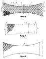
- FIG. 2 represents a side view of an end part of a second embodiment of a tutor according to the invention.
- FIG. 3 represents a side view of an end part of a third embodiment of a tutor according to the invention.
- FIG. 4 represents a side view of a fourth embodiment of a self-expanding tutor according to the invention.
- FIG. 5 represents a side view of a fifth embodiment of a tutor according to the invention.
- Figure 6 shows a side view of a sixth embodiment of a tutor according to the invention.
- Figure 7 shows a general diagram of the braiding apparatus and Figure 8 a more detailed view of the braiding operation.
- FIG. 9 represents a partial view of a tutor according to the invention at the end of manufacture.
- the self-expanding stakeholder is formed of a tubular body 1 having at the illustrated end a cylindrical shape.
- the tubular body 1 is formed of braided wires. It comprises first flexible rigid wires, for example 2 and 3, which are arranged side by side, here two in number, and which thus form first multiple wires wound in a first helical direction around the longitudinal axis 4 of the body tubular.
- second rigid wires 5 and 6 which are arranged side by side, here two in number, and which thus form multiple second wires wound in a second helical direction, opposite to the first. It is obvious that three, four or more wires can be provided arranged side by side to form a multiple wire according to the invention (see for example FIG. 5). It should also be noted that the wires arranged side by side to form a multiple wire are contiguous over almost their entire length. It is only for reasons of clarity and legibility of the figures that the wires forming a multiple wire, such as wires 2 and 3 or respectively 5 and 6, are shown slightly spaced from one another.
- the braiding mode can be variable as already indicated above. It appears in particular from FIG. 1A, that all the flexible wires forming the same multiple wire within the meaning of the invention follow a strictly parallel path in the braid.
- the multiple threads used consist of any material which is suitable for introduction into the human and animal body and which has sufficient rigidity and flexibility for the production of a self-expanding stake.
- Such threads meeting ISO 5832/7 and / or ASTM F1058-91 standards are highly desirable.
- the tubular body is shown in the rest state. In this state it presents, in this exemplary embodiment, a diameter D of approximately 28 mm. Its length is to be chosen according to the use of the tutor.
- the tutor In its working state, that is to say when it must be introduced into a known introducer, not shown, the tutor must have a diameter d which can reach 3 to 4 mm.
- the working state is obtained by radial compression on the tutor and / or by spacing the ends of the tutor in the axial direction. In the working state, the tutor therefore has a length greater than its length in the rest state.
- the arrangement of multiple wires according to the invention does not in any way hinder the obtaining of this working state of the tutor.
- the wires In this state of rest, the wires have, in the illustrated embodiments, with respect to a generator (7 in FIG. 2) of the tutor an angle of maximum 45 °, preferably less than this.
- This offers the great advantage that the tutor, in the working state, inserted in his introducer, does not have an excessive length with all the disadvantages of dropping that this raises, as already indicated previously.
- an angle of 45 ° is not critical for the invention and may, depending on the circumstances, be exceeded.
- the tubular body 1 can be coated on its internal surface with a covering 8 partially shown.
- This covering can be of any suitable biocompatible material, in particular for the manufacture of luminal stents (see EP-A-0603959).
- a covering on the external surface can be provided instead of the internal covering 8 or simultaneously with it.
- the use of multiple threads according to the invention also offers the advantage of a relatively large contact surface to have better adhesion with such a covering.
- FIG. 2 a tutor according to the invention is illustrated, the tubular body 1 of which has a flare at one end 9.
- the multiple wires follow a spatial spiral with increasing rays.
- the generator 7, at the place of the flare 9 forms a straight line which progressively deviates towards the outside of the axis 4.
- the flare 9 is therefore here of frustoconical shape.
- FIG. 3 a stake is illustrated, the tubular body 1 of which has a flare 10 at one end, the generator of which has the shape of a hyperbola segment.
- This flare gives rise to one end 10 of the stake 1, in the form of a truncated hyperboloid.
- the self-expanding stakeholder according to the invention is formed of a tubular body 1 having, in this example, a form of hyperboloid.
- the tubular body 1 is shown in the rest state. In this state it has, in this embodiment, a first flared end 11 of diameter D 1 and a second flared end 12 of diameter D 2 equal to D 1 . Halfway between these two flared ends is located a cross section 13 of the tubular body whose diameter D 3 is less than D 1 and D 2 .
- the diameter D 3 may for example be around 28 mm, and the diameters D 1 and D 2 equal for example 58 mm.
- the tubular body 1 has, in cross section, a diameter which decreases continuously. In the illustrated case, this reduction is such that the tubular body includes a generator 7 in the form of a hyperbola.
- the wires In the rest state, the wires have, in this illustrated embodiment, with respect to a generator 7 of the tutor an angle ⁇ which varies constantly. In its central part, this angle is preferably at most 45 °, advantageously less than this value. At the flared ends it is obviously much larger. This offers the great advantage that the tutor, in the working state, inserted in his introducer, does not have an excessive length with all the disadvantages of dropping that this raises, as already indicated previously. Furthermore, the radial relaxation of the ends is excellent and allows good attachment of the tutor, preventing migration of the latter during or after the release.
- FIG. 5 a tutor according to the invention is illustrated, the tubular body 1 of which has a first flared end 11 of diameter D 1 and a second end 12 of diameter D 2 less than D 1 .
- the cross section 13 of small diameter D 3 is located here at a shorter distance from the end 12 than from the end 11, which gives rise to a tubular body of asymmetrical shape.
- the tubular body comprises a straight-shaped generator, which progressively deviates outwards from the longitudinal axis 4, which gives rise to a form of tapered diabolo.
- the multiple wires braided according to a helix with increasing spokes have been shown in a partially broken manner.
- each multiple thread includes 3 threads arranged side by side.
- FIG. 6 a tutor is illustrated, the tubular body 1 of which has between its flared ends a generator in the form of a segment of a circle.
- the embodiments according to the invention illustrated in Figures 2 to 6 offer the great advantage of allowing good attachment of the guardian during the release, without subsequent migration into the cavity.
- the attachment to the wall thereof is more intense at the end which is the first dropped, thanks to its flared shape, and this retains the dropped device in the position that has been imposed on it.
- Such a tutor according to the invention proves to be very advantageous in particular during the introduction of a stent to treat an abdominal artery aneurysm. Its two ends follow the shape of the necks of the aneurysm, thus perfectly retaining the endoprosthesis, which is subjected at this point to the stresses of blood pressure.
- the central part of the tutor according to Figures 4 to 6, arched inward and recalled in this direction, perfectly withstands this blood pressure in the aneurysm, where no more radial compression is exerted on the tutor by the walls vascular.
- the stakes according to FIGS. 2 to 6 are also quite suitable for the treatment of subclavian artery aneurysms, where the stent can be strongly bent at one end. Instead of being crushed by closing at this end, like the cylindrical stakes of the prior art, the stake remains in a widely open position at its end, thanks to the shape thereof.
- FIGS. 7 and 8 appended The manufacture of a braided tubular body has been known for a long time in the cabling technique and use is made here of this technique which is illustrated in FIGS. 7 and 8 appended.
- a carrying cable 14 is unwound from a reel 15.
- a guide system generally designated by the reference 16 guides and brings under tension this cable 14 which then passes through the braiding machine 17 shown diagrammatically here. It leaves this machine, provided with a braided tubular body and it is thus wound on a coil 18 after having been brought under tension by a new guidance system 19.
- the braiding machine 17 used is shown in a little more detail in FIG. 8.
- a braiding machine of this kind it is possible, for example, to use a machine of the DBH or DB model put on the market by the firm Spiraltex, Meximieux, France.
- the spindles of such a machine (of which only a few have been shown) are divided into two groups, the spindles 20 of one group rotating in the opposite direction to the spindles 21 of the other group, around the axis of the braid.
- the carrying cable 14, not shown here, passes vertically through the middle of the braid.
- multiple threads 22 are unwound from each or part of the spindles.
- several threads were simultaneously wound on at least part of the spindles, preferably on all.
- these multiple threads coming from the spindles are almost contiguous over their entire length and that is why it was impossible to represent them in FIG. 8 other than in the form of a thread.
- the choice of the number of spindles depends on the diameter of the braid 23 desired.
- the braided tubular body has, at the end of the braiding, a diameter slightly greater than the diameter (for example D or D 3 ) of the finished tutor, in the rest state.
- the braided tubular body can then be removed from its carrying cable.
- this mandrel therefore has the shape of a cylinder of diameter, for example D, carrying a truncated cone at one end.
- the braided tubular body is then subjected to axial tension at its ends. It is for example, as in FIG. 9, knotted at 26 at one end, then at the other, which subjects it to a tension.
- the tubular body then follows the external shape of the mandrel 24. It is then subjected to a hardening heat treatment which fixes the tubular body to the dimensions of the mandrel. After this treatment, in the resting state, the tubular body has the shape illustrated in FIG. 2 or respectively in FIG. 4.
- the braided tubular body it is also provided, as a variant, to extend the braided tubular body and to introduce it into a tube 25, shown in lines. mixed in Figure 3 or Figure 6, which has an internal diameter equal to the desired diameter of the finished tutor. It is then subjected to the hardening heat treatment.
- a tubular braid 35 mm in diameter is introduced into a tube 28 mm in internal diameter.
- the wire is cured at 550 ° C for 3 hours, under an inert atmosphere (argon or nitrogen with 5% hydrogen) or under a vacuum of 10-5 torr.
- the finished tutor has a cylindrical shape as in the embodiment according to FIG. 1. If, on the other hand, one or more the two ends of the braid protrude from the tube 25 according to FIG. 3, these will automatically take the form of a truncated hyperboloid, as illustrated in this FIG. 3.
- the measurement method in these examples consists in evaluating the resistance to radial compression of the stakes.
- a loop of 0.12 mm diameter wire, attached at one end to a support, is passed around the stake to be examined, approximately in the middle of the support.
- Different weights are then suspended from the other end of the wire and the diameter is then measured at the constriction obtained for each weight suspended from the measuring wire.
- the tutor according to the prior art has in the state of rest a diameter of 32.77 mm and an angle of 52 °.
- the tutor according to the invention has in the idle state a diameter of 31.4 mm and an angle of 51 °.
- the angle of the wires with respect to a generator is 66 ° for the tutor according to the prior art, it is 49 ° for a tutor X according to the invention and 44 ° for a tutor Y according to the invention.
- the three examined stakes have an identical length, that is to say of approximately 10 cm.
- the tutor according to the prior art and the tutor Y were then introduced into an ID5 type Balt introducer (5 mm internal diameter) with a length of 50 cm.
- the tutor according to the prior art occupies a length of 44 cm, the tutor Y a length of 18 cm.
- the AC stakes have a diameter in the state of rest of 32 mm.
- the wires of the stakes A and B have an angle to a generator of 53.75 ° and 53.25 ° respectively, those of the stake C an angle of 55 °.
- stakes A and B can be manufactured on the same braiding machines as those used up to now (for example with 36 spindles).
Abstract
Description
La présente invention est relative à un tuteur auto-expansible pour dispositif médical à introduire dans inne cavité d'un corps humain ou animal, comprenant un corps tubulaire radialement expansible et rétractable entre un premier diamètre, correspondant à un état de travail du tuteur, et un deuxième diamètre supérieur au premier, correspondant à un état de repos du tuteur, et axialement expansible et rétractable entre inne première longueur, correspondant à l'état de travail, et une deuxième longueur inférieure a la première, correspondant à l'état de repos, ce corps tubulaire comportant des premiers fils rigides flexibles enroulés suivant un premier sens autour d'un axe longitudinal du corps tubulaire et des deuxièmes fils rigides flexibles enroulés suivant un deuxième sens inverse au premier autour de l'axe longitudinal susdit, chaque fit enroulé dans un desdits sens croisant des fils enroulés dans l'autre sens suivant inne disposition tressée, des fils précités pouvant se présenter soins la forme d'au moins un fit multiple.The present invention relates to a self-expanding stake for a medical device to be introduced into a cavity of a human or animal body, comprising a radially expandable tubular body which is retractable between a first diameter, corresponding to a work state of the stake, and a second diameter greater than the first, corresponding to a state of rest of the tutor, and axially expandable and retractable between a first length, corresponding to the working state, and a second length less than the first, corresponding to the state of rest , this tubular body comprising first flexible rigid wires wound in a first direction around a longitudinal axis of the tubular body and second flexible rigid wires wound in a second direction opposite to the first around the said longitudinal axis, each fit wound in one of said directions crossing wires wound in the other direction according to a braided arrangement, wires aforementioned can be presented in the form of at least one multiple fit.
On connaît depuis longtemps des tuteurs qui sont utilisés comme dilatateurs vasculaires, oesophagiens ou autres (GB-1205743). Ces tuteurs formés d'une tresse tubulaire de fils individuels comportent, à l'état de repos, des fils formant un angle assez petit par rapport à inne génératrice du tube, c'est-à-dire d'au maximum 30°. Les tuteurs de ce genre n'offrent pas une capacité d'expansion radiale suffisante lorsqu'ils sont libérés après avoir été radialement comprimés. Leur résistance à l'écrasement est également insuffisante lors de leur utilisation dans des cavités du corps dont les parois exercent une forte pression radiale sur le tuteur introduit.Tutors have long been known to be used as vascular, esophageal or other dilators (GB-1205743). These stakes formed of a tubular braid of individual threads comprise, in the state of rest, threads forming a fairly small angle with respect to a generator of the tube, that is to say at most 30 °. Guardians of this kind do not provide sufficient radial expansion capacity when released after being radially compressed. Their crushing resistance is also insufficient when used in body cavities whose walls exert a strong radial pressure on the introduced support.
On a par conséquent cherché à remédier à ces inconvénients en prévoyant un tressage des fils individuels suivant un angle plus grand, de façon que, à l'état de repos du tuteur, les fils présentent un angle supérieur à 45°, de préférence d'au moins 60° par rapport à une génératrice du tuteur (US-A-4655711 et US-A-4954126). Toutefois, les tuteurs à grand angle de tressage présentent un grand inconvénient. En effet, le tuteur tubulaire doit être allongé de 2 à 3 fois sa longueur initiale pour pouvoir être inséré dans un introducteur vasculaire. Il occupe alors de 40 à 50 % de la longueur de ce dernier, en le rigidifiant et en rendant compliqué son passage à travers la voie fémorale par laquelle l'introduction dans le corps est généralement amorcée. Lors du largage, la structure tubulaire se rétracte de deux à trois fois en longueur. Il est dès lors très difficile d'estimer la longueur qui va se déployer dans la cavité interne du corps traité et l'endroit précis où le tuteur va s'ancrer, ce qui peut entraîner de sérieux problèmes. Par exemple, une longueur de tuteur peut se déployer au-delà d'une bifurcation vasculaire et entraîner ainsi une fermeture d'artère non souhaitable, lorsque le tuteur est recouvert d'un revêtement, comme c'est le cas pour les endoprothèses luminales. Dans un autre cas, si la longueur déployée est trop courte, l'anévrisme traité ne sera pas fermé. Enfin, il est apparu que les tuteurs à grand angle de tressage et à fils individuels ne présentaient pas une bonne résistance à la pression artérielle, à l'intérieur des anévrismes traités. A l'intérieur de l'anévrisme, c'est-à-dire là où les tuteurs ne subissent plus de compression radiale de la part de la paroi vasculaire, ces derniers ont tendance à ballonner, ce qui favorise des pertes d'étanchéité.We have therefore sought to remedy these drawbacks by providing a braiding of the individual wires at a greater angle, so that, in the state of rest of the tutor, the wires have an angle greater than 45 °, preferably of at least 60 ° relative to a generator of the tutor (US-A-4655711 and US-A-4954126). However, stakes with a large braiding angle have a great drawback. Indeed, the tubular stake must be lengthened from 2 to 3 times its initial length to be able to be inserted into a vascular introducer. It then occupies 40 to 50% of the length of the latter, stiffening it and making it complicated to pass through the femoral route by which the introduction into the body is generally initiated. When dropped, the tubular structure retracts two to three times in length. It is therefore very difficult to estimate the length that will deploy in the internal cavity of the body being treated and the precise location where the tutor will anchor, which can cause serious problems. For example, a stake length can extend beyond a vascular bifurcation and thus lead to undesirable artery closure, when the stake is covered with a covering, as is the case with luminal stents. In another case, if the deployed length is too short, the treated aneurysm will not be closed. Finally, it appeared that tutors with a large braiding angle and individual wires did not exhibit good resistance to blood pressure, inside the treated aneurysms. Inside the aneurysm, that is to say where the guardians do not undergo more radial compression on the part of the vascular wall, the latter tend to balloon, which promotes leaks.
D'autres tresses tubulaires à base de fils, qui sont utilisées dans des dispositifs à introduire dans le corps humain, sont aussi décrites notamment dans EP-A-0183372, US-A-3509883, US-A-5061275 et US-A-5171262.Other tubular braids based on threads, which are used in devices to be introduced into the human body, are also described in particular in EP-A-0183372, US-A-3509883, US-A-5061275 and US-A- 5171262.
Dans le brevet US-A-5061275, en particulier, on a prévu la possibilité de façonner des corps tubulaires tressés dont les extrémités s'évasent de manière conique par rapport au reste du corps qui est de forme cylindrique. Sans résoudre le problème du ballonnement précité dans les anévrismes, cette forme de réalisation du tuteur ne permet que peu d'adaptation de la longueur au cas à traiter. Dès que le chirurgien découpe une longueur trop importante d'une extrémité par exemple d'une endoprothèse munie d'un tel tuteur, cette extrémité ne montre plus d'évasement et a perdu l'avantage que lui conférait ce dernier.In US-A-5061275, in particular, provision has been made for the possibility of shaping braided tubular bodies the ends of which widen conically with respect to the rest of the body which is cylindrical in shape. Without solving the aforementioned problem of bloating in aneurysms, this embodiment of the tutor allows little adaptation of the length to the case to be treated. As soon as the surgeon cuts an excessively long length of one end, for example of a stent fitted with such a tutor, this end no longer shows flaring and has lost the advantage which the latter conferred on it.
On connaît enfin des tuteurs en forme de tresses tubulaires expansibles pour des prothèses destinées à fournir des médicaments à l'intérieur du système vasculaire (WO 91/12779). Suivant une forme de réalisation décrite dans ce document, les filaments tressés se présentent sous la forme d'un fil multiple, trois filaments étant respectivement tordus ensemble en un toron pour former le fil multiple. Pour l'homme de métier moyen, il est clair qu'une telle forme de réalisation sera difficilement applicable. Elle va présenter un encombrement volumique insupportable et à l'endroit du croisement entre les torons il va se produire un frottement important. Enfin, à cause de ces torons, il va être compliqué de réduire suffisamment le diamètre du tuteur pour pouvoir l'insérer dans un introducteur. En cas de filaments métalliques, ceux-ci vont souffrir énormément et une casse n'est pas à exclure.Finally, there are known stakes in the form of expandable tubular braids for prostheses intended to supply medicaments inside the vascular system (WO 91/12779). According to an embodiment described in this document, the braided filaments are in the form of a multiple thread, three filaments being respectively twisted together in a strand to form the multiple thread. For the average person skilled in the art, it is clear that such an embodiment will be difficult to apply. It will have an unbearable volume size and at the point of crossing between the strands there will be significant friction. Finally, because of these strands, it will be complicated to reduce the diameter of the stake sufficiently enough to be able to insert it into an introducer. In metal filaments, these will suffer enormously and breakage cannot be excluded.
Lors d'essais de fabrication de tresse en fils toronnés, on a observé que, pendant le traitement thermique la structure torsadée contenait des particules qui restaient emprisonnées à l'intérieur de celle-ci, particules très difficiles à extraire, même par nettoyage aux ultrasons. Or, la propreté de la structure qui va être en contact avec le sang est d'une importance capitale, et ces particules peuvent affecter la biocompatibilité de l'endoprothèse.During tests for making a braid from stranded wires, it was observed that, during the heat treatment, the twisted structure contained particles which remained trapped inside it, particles which are very difficult to extract, even by ultrasonic cleaning. . However, the cleanliness of the structure that will be in contact with the blood is of paramount importance, and these particles can affect the biocompatibility of the stent.
Suivant l'invention on a résolu les problèmes mentionnés ci-dessus par un tuteur auto-expansible tel que décrit au début, dans lequel chaque fil multiple susdit comprend des fils rigides flexibles susdits, qui sont disposés côté à côté au nombre d'au moins deux en suivant un parcours parallèle dans la disposition tressée. Un tel tuteur présente une grande stabilité dimensionnelle et géométrique, sans nécessiter de grand angle de tressage et, de ce fait, la précision au largage de ce tuteur en est fortement augmentée. Par ailleurs, on peut réduire sans problème le diamètre d'un tel tuteur à celui d'un introducteur courant, les fils multiples utilisés suivant l'invention ne présentant aucune entrave à cela.According to the invention, the problems mentioned above have been solved by a self-expanding stakeholder as described at the start, in which each aforesaid multiple threads comprises the above flexible rigid threads, which are arranged side by side at least as many two following a parallel route in the braided layout. Such a tutor has great dimensional and geometric stability, without requiring a large braiding angle and, therefore, the release precision of this tutor is greatly increased. Furthermore, the diameter of such a stake can be reduced without problem to that of a common introducer, the multiple wires used according to the invention having no obstacle to this.
Avantageusement tous les premiers fils susdits et tous les deuxièmes fils susdits forment des fils multiples susdits.Advantageously, all of the above-mentioned first wires and all of the above-mentioned second wires form multiple wires.
Par tuteur auto-expansible, il faut entendre suivant l'invention que, amené dans sa position de travail, c'est-à-dire une position radialement comprimée et axialement étendue, le tuteur, une fois libéré, tend à récupérer spontanément sa position de repos, c'est-à-dire une position radialement expansée et axialement contractée.By self-expanding tutor, it should be understood according to the invention that, brought into its working position, that is to say a radially compressed and axially extended position, the tutor, once released, tends to spontaneously recover its position of rest, that is to say a radially expanded and axially contracted position.
Dans la disposition tressée des fils, dans certaines formes de réalisation, un premier fil multiple va, lors d'un croisement avec un deuxième fil multiple, passer par-dessus celui-ci et lors du croisement suivant passer en dessous du deuxième fil alors croisé, et ainsi de suite. Dans d'autres formes de réalisation, le premier fil multiple passe au-dessus d'un deuxième fil multiple à deux croisements successifs ou davantage et passera alors seulement en dessous d'un deuxième fil multiple après plusieurs croisements successifs et ainsi de suite. Des dispositions tressées mixtes peuvent aussi être prévues, ainsi que des tresses formées partiellement de doubles fils et de monofils.In the braided arrangement of the threads, in certain embodiments, a first multiple thread will, when crossing with a second multiple thread, pass over the latter and during the following crossing pass below the second thread then crossed , And so on. In other embodiments, the first multiple thread passes over a second multiple thread at two or more successive crosses and will then only pass below a second multiple thread after several successive crosses and so on. Mixed braided arrangements can also be provided, as well as braids partially formed from double threads and monofilaments.
De toutes manières, par fils multiples suivant l'invention, il faut entendre que les fils rigides flexibles, qui les forment, sont disposés côte à côte et suivent un parcours parallèle dans la disposition tressée. Dès le moment où deux fils voisins ne suivent plus le même parcours, c'est-à-dire par exemple que l'un croise un fil enroulé en sens inverse en passant par-dessus tandis que l'autre croise ce même fil enroulé en sens inverse en passant en dessous, il ne s'agit plus de fils formant un fil multiple au sens de la présente invention. Les fils formant un même fil multiple peuvent être jointifs ou disposés à très faible distance l'un de l'autre.In any case, by multiple threads according to the invention, it should be understood that the flexible rigid threads, which form them, are placed side by side and follow a parallel path in the braided arrangement. As soon as two neighboring wires no longer follow the same route, that is to say for example that one crosses a wound wire in the opposite direction by passing over it while the other crosses the same wound wire in opposite direction by passing below, it is no longer a question of wires forming a multiple wire within the meaning of the present invention. The wires forming the same multiple wire can be joined or arranged at a very short distance from each other.
Par dispositif médical à introduire dans une cavité d'un corps humain ou animal, il faut entendre par exemple les endoprothèses luminales, les cathéters, les dilatateurs, les greffes et analogues qui peuvent être introduits par exemple dans des cavités vasculaires, oesophagiennes, urinaires, uretérales, biliaires, et autres conduits tubulaires du corps.The term “medical device to be introduced into a cavity of a human or animal body” is intended to mean, for example, luminal stents, catheters, dilators, grafts and the like which can be introduced for example into vascular, esophageal, urinary, ureteral, biliary, and other tubular conduits of the body.
Suivant une forme particulière de l'invention, au moins à une de ses extrémités, le corps tubulaire formé de fils multiples tressés présente, à l'état de repos, un évasement où les fils multiples suivent une spirale spatiale à rayons croissants. Une telle forme de réalisation est particulièrement intéressante pour le traitement par exemple d'anévrismes aortiques, où il se produit un rétrécissement du collet de l'anévrisme proximal ou distal. Le tuteur suivant l'invention, en particulier son extrémité évasée, présente une résistance à l'écrasement par la paroi artérielle du fait du rétrécissement du collet. La détente radiale de la partie évasée du tuteur favorise en outre l'absence de migration le long de la paroi de la cavité où il doit être appliqué.According to a particular form of the invention, at least at one of its ends, the tubular body formed of braided multiple threads presents, in the state of rest, a flare where the multiple threads follow a spatial spiral with increasing rays. Such an embodiment is particularly advantageous for the treatment for example of aortic aneurysms, where there is a narrowing of the neck of the proximal or distal aneurysm. The tutor according to the invention, in particular its flared end, has a resistance to crushing by the arterial wall due to the narrowing of the collar. The radial expansion of the flared part of the support also promotes the absence of migration along the wall of the cavity where it must be applied.
Il est prévu, suivant une forme très avantageuse de l'invention, un évasement à l'extrémité du tuteur dont les génératrices se terminent en hyperbole. Comme on le verra par la suite, cette forme de réalisation présente le grand avantage d'une très grande simplicité de fabrication et d'une reproductibilité parfaite de l'angle de tressage.According to a very advantageous form of the invention, there is a flaring at the end of the tutor whose generatrices end in hyperbola. As will be seen later, this embodiment has the great advantage of a very simple manufacturing and perfect reproducibility of the braiding angle.
Il est aussi prévu, suivant la présente invention, que le corps tubulaire du tuteur comporte, à l'état de repos, deux extrémités évasées de grand diamètre et, entre celles-ci, une section transversale de corps tubulaire de petit diamètre et que, depuis chacune des extrémités évasées jusqu'à la section de petit diamètre, le corps tubulaire présence en section transversale un diamètre diminuant de manière continue. Par cette forme de réalisation, le tuteur s'oppose à tout ballonnement à l'intérieur d'un anévrisme, tout en conservant ses bonnes propriétés d'accrochage par ses extrémités évasées, lors du largage dans une cavité tubulaire d'un corps humain ou animal. Et cela, même si le chirurgien a réduit par découpage une partie de la longueur du tuteur. La nouvelle extrémité formée reste encore évasée par rapport au reste du tuteur. Enfin, la détente radiale des parties évasées du tuteur reste maintenue lors du largage, et les parties évasées, en épousant parfaitement les formes des parois vasculaires où elles sont larguées empêchent de manière efficace une migration du tuteur le long de ces parois.It is also provided, according to the present invention, that the tubular body of the stake comprises, in the state of rest, two flared ends of large diameter and, between them, a cross section of tubular body of small diameter and that, from each of the flared ends to the small diameter section, the tubular body in cross section has a continuously decreasing diameter. By this embodiment, the tutor opposes any bloating inside an aneurysm, while retaining its good attachment properties by its flared ends, when dropping a human body into a tubular cavity. animal. And that, even if the surgeon cut part of the length of the tutor by cutting. The new end formed remains still flared compared to the rest of the tutor. Finally, the radial relaxation of the flared parts of the tutor remains maintained during the release, and the flared parts, by perfectly matching the shapes of the vascular walls where they are released effectively prevent migration of the tutor along these walls.
Il est prévu, suivant une forme avantageuse de l'invention, que, entre au moins l'une des extrémités évasées et la section transversale de petit diamètre, le corps tubulaire comporte une genératrice en forme de droite. Suivant une forme de réalisation préférée de l'invention, entre au moins l'une des extrémités évasées et la section transversale de petit diamètre, le corps tubulaire comporte une génératrice en forme de demi-hyperbole. Dans ce cas, le tuteur a une forme d'hyperboloïde. Suivant une autre forme de réalisation de l'invention, entre au moins l'une des extrémités évasées et la section transversale de petit diamètre, le corps tubulaire comporte une génératrice en forme de segment de cercle.It is provided, according to an advantageous form of the invention, that, between at least one of the flared ends and the cross section of small diameter, the tubular body comprises a generator in the form of a straight line. According to a preferred embodiment of the invention, between at least one of the flared ends and the cross section of small diameter, the tubular body comprises a generator in the form of a half-hyperbola. In this case, the tutor has a form of hyperboloid. According to another embodiment of the invention, between at least one of the flared ends and the cross section of small diameter, the tubular body comprises a generator in the form of a segment of a circle.
A l'état de repos, le corps tubulaire comporte avantageusement des fils multiples orientés sous un angle égal, de préférence inférieur, à 45° par rapport à une de ses génératrices. Suivant l'invention, l'angle de tressage n'a pas besoin d'être élevé, pour obtenir de bonnes propriétés de stabilité dimensionnelle. Par conséquent, il s'ensuit une amélioration notable du largage du tuteur dans la cavité où il doit être appliqué.In the idle state, the tubular body advantageously comprises multiple wires oriented at an angle equal to, preferably less than, 45 ° relative to one of its generatrices. According to the invention, the braiding angle does not need to be large, to obtain good dimensional stability properties. Consequently, there results a significant improvement in the release of the tutor into the cavity where it is to be applied.
Suivant une autre forme avantageuse de réalisation de l'invention, le corps tubulaire présente une surface de paroi externe et une surface de paroi interne et il comporte sur au moins une de ces deux surfaces de paroi un recouvrement expansible. Un tel recouvrement peut être appliqué sur le tuteur selon n'importe quelle technique connue, par exemple conformément à l'enseignement de la EP-A-0603959. Cela permet de former par exemple des endoprothèses luminales de 40 mm de diamètre au repos, dont le recouvrement est réalisé en fibres de polycarbonate-uréthanne ou autres d'un diamètre de fibre de 10-20 µm. Le diamètre de telles endoprothèses peut alors être réduit à un diamètre de 4 à 5 mm pour l'insertion dans un introducteur. Il est bien entendu que le recouvrement peut être d'une nature différente et qu'il peut être réalisé selon d'autres techniques bien connues, sans sortir du cadre de l'invention.According to another advantageous embodiment of the invention, the tubular body has an external wall surface and an internal wall surface and it comprises on at least one of these two wall surfaces an expandable covering. Such a covering can be applied to the tutor according to any known technique, for example in accordance with the teaching of EP-A-0603959. This makes it possible, for example, to form luminal stents 40 mm in diameter at rest, the covering of which is made of polycarbonate-urethane fibers or the like with a fiber diameter of 10-20 μm. The diameter of such stents can then be reduced to a diameter of 4 to 5 mm for insertion into an introducer. It is understood that the recovery can be of a different nature and that it can be carried out according to other well known techniques, without departing from the scope of the invention.
L'invention a également pour objet un dispositif médical à introduire dans une cavité d'un corps humain ou animal, qui comprend un tuteur auto-expansible suivant l'invention.The invention also relates to a medical device to be introduced into a cavity of a human or animal body, which comprises a self-expanding stakeholder according to the invention.
Il est également prévu suivant l'invention un procédé de préparation d'un tuteur auto-expansible pour dispositif médical à introduire dans une cavité d'un corps, comprenant un tressage de fils provenant de fuseaux intercalés tournant en sens inverse, de façon à former un corps tubulaire radialement expansible et rétractable entre un premier diamètre, correspondant à un état de travail du tuteur, et un deuxième diamètre supérieur au premier, correspondant à un état de repos du tuteur, et axialement expansible et rétractable entre une première longueur, correspondant à l'état de travail, et une deuxième longueur inférieure à la première, correspondant à l'état de repos, le tressage comprenant un enroulement de premiers fils rigides flexibles suivant un premier sens hélicoïdal autour d'un axe longitudinal du corps tubulaire et un enroulement de deuxièmes fils rigides flexibles suivant un deuxième sens hélicoïdal inverse au premier, chaque fil enroulé dans un desdits sens hélicoïdaux croisant des fils multiples enroulés dans l'autre sens hélicoïdal, des fils précités pouvant se présenter sous la forme d'au moins un fil multiple.According to the invention, there is also provided a method for preparing a self-expanding tutor for a medical device to be introduced into a body cavity, comprising a braiding of threads coming from interposed spindles rotating in opposite directions, so as to form a radially expandable and retractable tubular body between a first diameter, corresponding to a working state of the tutor, and a second diameter greater than the first, corresponding to a state of rest of the tutor, and axially expandable and retractable between a first length, corresponding to the working state, and a second length less than the first, corresponding to the rest state, the braiding comprising a winding of flexible first rigid wires in a first helical direction around a longitudinal axis of the tubular body and a winding second flexible rigid wires in a second helical direction opposite to the first, each wire wound d in one of said helical directions crossing multiple wires wound in the other helical direction, aforementioned threads which may be in the form of at least one multiple thread.
On connaît depuis longtemps dans le domaine de la câblerie la fabrication de tresses tubulaires formées de fils métalliques. Les problèmes à résoudre dans ce domaine sont toutefois totalement différents et les exigences posées aux tresses dans la câblerie sont tout à fait distinctes. Un procédé de tressage de tuteur auto-expansible est évoqué dans le US-A-5061275.The manufacture of tubular braids formed from metal wires has long been known in the cable industry. The problems to be solved in this field are however completely different and the requirements for braids in the cable industry are quite distinct. A self-expanding tutor braiding process is discussed in US-A-5061275.
Suivant l'invention on prévoit que le procédé décrit ci-dessus comprend, préalablement au tressage, un envidage d'au moins un fuseau par des fils susdits disposés côte à côte au nombre d'au moins deux, pour former ledit au moins un fil multiple, et, pendant l'enroulement, les fils formant un fil multiple suivent un parcours parallèle.According to the invention, it is provided that the process described above comprises, before braiding, an emptying of at least one spindle by said threads arranged side by side at least two in number, to form said at least one thread. multiple, and, during winding, the wires forming a multiple wire follow a parallel path.
Un tel procédé permet la fabrication d'un tuteur beaucoup plus performant que ceux de la technique antérieure, sans devoir modifier l'appareillage existant, et donc sans investissement supplémentaire. Il ne comprend pas non plus d'étape préalable de fabrication d'un multifil, tel qu'un toron par exemple.Such a method allows the manufacture of a tutor much more efficient than those of the prior art, without having to modify the existing apparatus, and therefore without additional investment. It also does not include a prior step of manufacturing a multi-wire, such as a strand for example.
Suivant un mode de réalisation particulier de l'invention, le procédé comprend un tressage du corps tubulaire à un diamètre supérieur au deuxième diamètre précité, une expansion axiale du corps tubulaire tressé, notamment par son introduction dans un tube à forme interne prédéterminée, et un traitement thermique de durcissement du corps tubulaire ainsi axialement expansé pour le fixer de façon que, après ce traitement, il soit à l'état de repos lorsqu'il présente une forme correspondant à celle de la cavité interne du tube. Ce mode de réalisation permet d'obtenir des angles entre les fils et une génératrice du tuteur parfaitement reproductibles après l'étape de fixation du corps tubulaire dans sa forme correspondant à l'état de repos. Le tube peut avoir une forme quelconque appropriée, à cavité par exemple cylindrique ou d'hyperboloïde.According to a particular embodiment of the invention, the method comprises braiding the tubular body to a diameter greater than the second diameter mentioned above, an axial expansion of the braided tubular body, in particular by its introduction into a tube with a predetermined internal shape, and a heat treatment for hardening the tubular body thus axially expanded to fix it so that, after this treatment, it is in the rest state when it has a shape corresponding to that of the internal cavity of the tube. This embodiment makes it possible to obtain angles between the wires and a generator of the stake which are perfectly reproducible after the step of fixing the tubular body in its shape corresponding to the state of rest. The tube can have any suitable shape, for example cylindrical or hyperboloid cavity.
Suivant un mode perfectionné de réalisation de l'invention, après l'introduction du corps tubulaire tressé dans ledit tube, au moins une de ses extrémités dépasse du tube, en s'évasant. Ainsi, après le traitement thermique de durcissement précité, le tuteur peut être fixé, à l'état de repos, avec un évasement à au moins une de ses extrémités. Dans ce mode de réalisation, l'évasement en question peut prendre automatiquement une forme telle qu'il comporte une génératrice en forme de segment d'hyperbole.According to an improved embodiment of the invention, after the introduction of the braided tubular body into said tube, at least one of its ends protrudes from the tube, flaring out. Thus, after the aforementioned hardening heat treatment, the stake can be fixed, in the rest state, with a flare at at least one of its ends. In this embodiment, the flare in question can automatically take a form such that it includes a generator in the form of a hyperbola segment.
Suivant encore un mode de réalisation de l'invention, le procédé comprend, après le tressage, un enfilage du corps tubulaire tressé autour d'un mandrin de forme appropriée, une tension aux extrémités du corps tubulaire pour l'appliquer sur le mandrin, un traitement thermique de durcissement du corps tubulaire ainsi axialement tendu pour le fixer de façon que, après ce traitement, il présente à l'état de repos la forme du mandrin.According to yet another embodiment of the invention, the method comprises, after braiding, threading the braided tubular body around a mandrel of suitable shape, a tension at the ends of the tubular body to apply it to the mandrel, a heat treatment for hardening the tubular body thus axially stretched to fix it so that, after this treatment, it has the shape of the mandrel in the state of rest.
D'autres détails et particularités de l'invention sont indiqués dans les revendications annexées.Other details and features of the invention are indicated in the appended claims.
L'invention va à présent être décrite de manière plus détaillée dans la description qui suit de formes de réalisation non limitatives et avec référence aux dessins annexés.The invention will now be described in more detail in the following description of non-limiting embodiments and with reference to the accompanying drawings.
La figure 1 représente une vue latérale d'une partie d'extrémité d'une forme de réalisation de tuteur auto-expansible suivant l'invention.Figure 1 shows a side view of an end portion of an embodiment of a self-expanding stakeholder according to the invention.
La figure 1A représente, à l'échelle agrandie, un détail du tressage des fils multiples du tuteur de la figure 1.FIG. 1A represents, on an enlarged scale, a detail of the braiding of the multiple threads of the tutor of FIG. 1.
La figure 2 représente une vue latérale d'une partie d'extrémité d'une deuxième forme de réalisation de tuteur suivant l'invention.FIG. 2 represents a side view of an end part of a second embodiment of a tutor according to the invention.
La figure 3 représente une vue latérale d'une partie d'extrémité d'une troisième forme de réalisation de tuteur suivant l'invention.FIG. 3 represents a side view of an end part of a third embodiment of a tutor according to the invention.
La figure 4 représente une vue latérale d'une quatrième forme de réalisation de tuteur auto-expansible suivant l'invention.FIG. 4 represents a side view of a fourth embodiment of a self-expanding tutor according to the invention.
La figure 5 représente une vue latérale d'une cinquième forme de réalisation de tuteur suivant l'invention.FIG. 5 represents a side view of a fifth embodiment of a tutor according to the invention.
La figure 6 représente une vue latérale d'une sixième forme de réalisation de tuteur suivant l'invention.Figure 6 shows a side view of a sixth embodiment of a tutor according to the invention.
La figure 7 représente un schéma général de l'appareillage de tressage et la figure 8 une vue plus détaillée de l'opération de tressage.Figure 7 shows a general diagram of the braiding apparatus and Figure 8 a more detailed view of the braiding operation.
La figure 9 représente une vue partielle d'un tuteur suivant l'invention en fin de fabrication.FIG. 9 represents a partial view of a tutor according to the invention at the end of manufacture.
Sur les différentes figures, les éléments identiques ou analogues portent les mêmes références.In the various figures, identical or analogous elements have the same references.
Ainsi qu'il ressort de la figure 1 le tuteur auto-expansible suivant l'invention, illustré partiellement, est formé d'un corps tubulaire 1 présentant à l'extrémité illustrée une forme cylindrique. Le corps tubulaire 1 est formé de fils tressés. Il comprend des premiers fils rigides flexibles, par exemple 2 et 3, qui sont disposés côte à côte, ici au nombre de deux, et qui forment ainsi des premiers fils multiples enroulés suivant un premier sens hélicoïdal autour de l'axe longitudinal 4 du corps tubulaire.As is apparent from Figure 1 the self-expanding stakeholder according to the invention, partially illustrated, is formed of a
Il comprend aussi des deuxièmes fils rigides 5 et 6 qui sont disposés côte à côte, ici au nombre de deux, et qui forment ainsi des deuxièmes fils multiples enroulés suivant un deuxième sens hélicoïdal, inverse au premier. Il est évident qu'on peut prévoir trois, quatre ou davantage de fils disposés côte à côte pour former un fil multiple suivant l'invention (voir par exemple figure 5). Il faut aussi noter que les fils disposés côte à côte pour former un fil multiple sont contigus sur quasiment la totalité de leur longueur. C'est uniquement pour des raisons de clarté et de lisibilité des figures que les fils formant un fil multiple, comme les fils 2 et 3 ou respectivement 5 et 6, sont représentés légèrement écartés l'un de l'autre.It also includes second
Comme on peut le voir sur les figures 1 à 3, les fils multiples du corps tubulaire 1 se croisent suivant une disposition tressée, le mode de tressage pouvant être variable comme on l'a déjà indiqué précédemment. Il ressort en particulier de la figure 1A, que tous les fils flexibles formant un même fil multiple au sens de l'invention suivent un parcours rigoureusement parallèle dans la tresse.As can be seen in Figures 1 to 3, the multiple son of the
Les fils multiples utilisés sont constitués de toute matière qui est appropriée pour l'introduction dans le corps humain et animal et qui présente une rigidité et une flexibilité suffisantes pour la réalisation d'un tuteur auto-expansible. On peut par exemple prévoir des fils métalliques inoxydables, biocompatibles. De tels fils répondant aux normes ISO 5832/7 et/ou ASTM F1058-91 sont hautement souhaitables. On peut par exemple citer des fils PHYNOX à désignation AFNOR : K13 C20 N16 Fe15 Do7, mis sur le marché par la firme Sprint Metal, Paris, France. Il est bien entendu que d'autres fils métalliques ou des fils en d'autres matières, par exemple en matières plastiques à mémoire élastique peuvent être utilisés.The multiple threads used consist of any material which is suitable for introduction into the human and animal body and which has sufficient rigidity and flexibility for the production of a self-expanding stake. One can for example provide stainless steel wires, biocompatible. Such threads meeting ISO 5832/7 and / or ASTM F1058-91 standards are highly desirable. We can for example mention PHYNOX wires with AFNOR designation: K13 C20 N16 Fe15 Do7, put on the market by the firm Sprint Metal, Paris, France. It is understood that other metallic wires or wires made of other materials, for example plastics with elastic memory can be used.
Sur la figure 1, le corps tubulaire est représenté à l'état de repos. Dans cet état il présente, dans cet exemple de réalisation, un diamètre D d'environ 28 mm. Sa longueur est à choisir en fonction de l'utilisation du tuteur. Dans son état de travail, c'est-à-dire au moment où il devra être introduit dans un introducteur connu, non représenté, le tuteur devra présenter un diamètre d qui peut atteindre 3 à 4 mm. L'état de travail est obtenu par compression radiale sur le tuteur et/ou par écartement des extrémités du tuteur en direction axiale. A l'état de travail, le tuteur présente donc une longueur supérieure à sa longueur à l'état de repos. L'agencement des fils multiples suivant l'invention n'entrave en aucune manière l'obtention de cet état de travail du tuteur.In Figure 1, the tubular body is shown in the rest state. In this state it presents, in this exemplary embodiment, a diameter D of approximately 28 mm. Its length is to be chosen according to the use of the tutor. In its working state, that is to say when it must be introduced into a known introducer, not shown, the tutor must have a diameter d which can reach 3 to 4 mm. The working state is obtained by radial compression on the tutor and / or by spacing the ends of the tutor in the axial direction. In the working state, the tutor therefore has a length greater than its length in the rest state. The arrangement of multiple wires according to the invention does not in any way hinder the obtaining of this working state of the tutor.
A cet état de repos, les fils présentent, dans les formes de réalisation illustrées, par rapport à une génératrice (7 sur la figure 2) du tuteur un angle au maximum de 45°, de préférence inférieur à celui-ci. Cela offre le grand avantage que le tuteur, à l'état de travail, inséré dans son introducteur, n'a pas une longueur excessive avec tous les inconvénients de largage que cela soulève, comme déjà indiqué précédemment. Un tel angle de 45° n'est toutefois pas critique pour l'invention et peut selon les circonstances être dépassé.In this state of rest, the wires have, in the illustrated embodiments, with respect to a generator (7 in FIG. 2) of the tutor an angle of maximum 45 °, preferably less than this. This offers the great advantage that the tutor, in the working state, inserted in his introducer, does not have an excessive length with all the disadvantages of dropping that this raises, as already indicated previously. However, such an angle of 45 ° is not critical for the invention and may, depending on the circumstances, be exceeded.
Comme on peut le voir sur la figure 1, le corps tubulaire 1 peut être revêtu sur sa surface interne d'un recouvrement 8 partiellement représenté. Ce recouvrement peut être en n'importe quelle matière biocompatible appropriée, notamment pour la fabrication d'endoprothèses luminales (voir EP-A-0603959). Un recouvrement sur la surface externe peut être prévu au lieu du recouvrement interne 8 ou simultanément à celui-ci. L'utilisation de fils multiples suivant l'invention offre en outre l'avantage d'une relativement grande surface de contact pour avoir une meilleure adhésion avec un tel recouvrement.As can be seen in FIG. 1, the
Sur la figure 2, est illustré un tuteur suivant l'invention dont le corps tubulaire 1 présente à une extrémité un évasement 9. Comme on peut le voir, à cet endroit, les fils multiples suivent une spirale spatiale à rayons croissants. Dans cet exemple de réalisation, la génératrice 7, à l'endroit de l'évasement 9, forme une droite qui s'écarte progressivement vers l'extérieur de l'axe 4. L'évasement 9 est donc ici de forme tronconique.In FIG. 2, a tutor according to the invention is illustrated, the
Sur la figure 3, est illustré un tuteur dont le corps tubulaire 1 présente à une extrémité un évasement 10 dont la génératrice a une forme de segment d'hyperbole. Cet évasement donne lieu à une extrémité 10 du tuteur 1, en forme d'hyperboloïde tronqué.In FIG. 3, a stake is illustrated, the
Ainsi qu'il ressort de la figure 4, le tuteur auto-expansible suivant l'invention est formé d'un corps tubulaire 1 présentant dans cet exemple une forme d'hyperboloïde.As can be seen from FIG. 4, the self-expanding stakeholder according to the invention is formed of a
Sur la figure 4, le corps tubulaire 1 est représenté à l'état de repos. Dans cet état il présente, dans cet exemple de réalisation, une première extrémité évasée 11 de diamètre D1 et une deuxième extrémité évasée 12 de diamètre D2 égal à D1. A mi-distance de ces deux extrémités évasées est située une section transversale 13 du corps tubulaire dont le diamètre D3 est inférieur à D1 et D2. Le diamètre D3 peut être par exemple d'environ 28 mm, et les diamètres D1 et D2 égaux à par exemple 58 mm. Entre chaque extrémité évasée 11 ou 12 et la section transversale 13 de petit diamètre, le corps tubulaire 1 présente, en section transversale, un diamètre qui diminue de manière continue. Dans le cas illustré cette diminution est telle que le corps tubulaire comporte une génératrice 7 en forme d'hyperbole.In Figure 4, the
A l'état de repos, les fils présentent, dans cette forme de réalisation illustrée, par rapport à une génératrice 7 du tuteur un angle α qui varie constamment. Dans sa partie centrale, cet angle est de préférence au maximum de 45°, avantageusement inférieur à cette valeur. Aux extrémités évasées il est évidemment beaucoup plus grand. Cela offre le grand avantage que le tuteur, à l'état de travail, inséré dans son introducteur, n'a pas une longueur excessive avec tous les inconvénients de largage que cela soulève, comme déjà indiqué précédemment. Par ailleurs, la détente radiale des extrémités est excellente et permet un bon accrochage du tuteur, en empêchant une migration de celui-ci au cours ou après le largage.In the rest state, the wires have, in this illustrated embodiment, with respect to a generator 7 of the tutor an angle α which varies constantly. In its central part, this angle is preferably at most 45 °, advantageously less than this value. At the flared ends it is obviously much larger. This offers the great advantage that the tutor, in the working state, inserted in his introducer, does not have an excessive length with all the disadvantages of dropping that this raises, as already indicated previously. Furthermore, the radial relaxation of the ends is excellent and allows good attachment of the tutor, preventing migration of the latter during or after the release.
Sur la figure 5, est illustré un tuteur suivant l'invention dont le corps tubulaire 1 présente une première extrémité évasée 11 de diamètre D1 et une deuxième extrémité 12 de diamètre D2 inférieur à D1. La section transversale 13 de petit diamètre D3 est située ici à une distance plus courte de l'extrémité 12 que de l'extrémité 11, ce qui donne lieu à un corps tubulaire de forme asymétrique. Entre chaque extrémité évasée 11 ou 12, et la section transversale 13 de petit diamètre, le corps tubulaire comporte une génératrice en forme de droite, qui s'écarte progressivement vers l'extérieur de l'axe longitudinal 4, ce qui donne lieu à une forme de diabolo tronconique. Dans cet exemple de réalisation, les fils multiples tressés suivant une hélice à rayons croissants ont été représentés de manière partiellement brisée. Ici chaque fil multiple comprend 3 fils disposés côte à côte.In FIG. 5, a tutor according to the invention is illustrated, the
Sur la figure 6, est illustré un tuteur dont le corps tubulaire 1 comporte entre ses extrémités évasées une génératrice en forme de segment de cercle.In FIG. 6, a tutor is illustrated, the
Il est évident qu'on peut prévoir une série d'autres génératrices pour réaliser un tuteur suivant l'invention, par exemple un segment d'ellipse, d'ovale, d'hypocycloïde, de parabole, de caténoïde, et de courbes analogues.It is obvious that a series of other generators can be provided to make a tutor according to the invention, for example a segment of ellipse, oval, hypocycloid, parabola, catenoid, and similar curves.
Il doit être entendu que les génératrices de part et d'autre de la section transversale de petit diamètre peuvent être de nature et de valeur différentes.It should be understood that the generators on either side of the small diameter cross section may be of different nature and value.
Les formes de réalisation suivant l'invention illustrées sur les figures 2 à 6 offrent le grand avantage de permettre une bonne fixation du tuteur lors du largage, sans migration ultérieure dans la cavité. L'accrochage à la paroi de celle-ci se fait de manière plus intense à l'extrémité qui est la première larguée, grâce à sa forme évasée, et celle-ci retient le dispositif largué dans la position qu'on lui a imposé. Un tel tuteur suivant l'invention, à deux extrémités évasées, s'avère très avantageux notamment lors de l'introduction d'une endoprothèse pour traiter un anévrisme d'artère abdominale. Ses deux extrémités épousent la forme des collets de l'anévrisme en retenant ainsi parfaitement l'endoprothèse, qui est soumise à cet endroit aux sollicitations de la pression artérielle. La partie centrale du tuteur suivant les figures 4 à 6, cambrée vers l'intérieur et rappelée dans ce sens, résiste parfaitement à cette pression artérielle dans l'anévrisme, là où plus aucune compression radiale n'est excercée sur le tuteur par les parois vasculaires.The embodiments according to the invention illustrated in Figures 2 to 6 offer the great advantage of allowing good attachment of the guardian during the release, without subsequent migration into the cavity. The attachment to the wall thereof is more intense at the end which is the first dropped, thanks to its flared shape, and this retains the dropped device in the position that has been imposed on it. Such a tutor according to the invention, with two flared ends, proves to be very advantageous in particular during the introduction of a stent to treat an abdominal artery aneurysm. Its two ends follow the shape of the necks of the aneurysm, thus perfectly retaining the endoprosthesis, which is subjected at this point to the stresses of blood pressure. The central part of the tutor according to Figures 4 to 6, arched inward and recalled in this direction, perfectly withstands this blood pressure in the aneurysm, where no more radial compression is exerted on the tutor by the walls vascular.
Les tuteurs suivant les figures 2 à 6 sont aussi tout à fait appropriés pour le traitement d'anévrismes d'artère sous-clavière, où le tuteur peut se trouver fortement coudé à une extrémité. Au lieu de s'écraser en se refermant à cette extrémité, comme les tuteurs cylindriques de l'art antérieur, le tuteur reste dans une position largement ouverte à son extrémité, grâce à la forme de celle-ci.The stakes according to FIGS. 2 to 6 are also quite suitable for the treatment of subclavian artery aneurysms, where the stent can be strongly bent at one end. Instead of being crushed by closing at this end, like the cylindrical stakes of the prior art, the stake remains in a widely open position at its end, thanks to the shape thereof.
Un sectionnement de l'endoprothèse, et donc de son tuteur, par le chirurgien pour une mise à longueur juste avant le traitement ne présente aucun risque, car la forme évasée aux extrémités subsiste malgré cette découpe de dernière minute. Des problèmes de stockage d'endoprothèses de longueurs variables sont ainsi résolus.Cutting the endoprosthesis, and therefore its tutor, by the surgeon for cutting to length just before the treatment presents no risk, because the flared shape at the ends remains despite this last minute cut. Problems in storing stents of variable lengths are thus resolved.
La fabrication d'un corps tubulaire tressé est connue depuis longtemps dans la technique de la câblerie et on fait usage ici de cette technique qui est illustrée sur les figures 7 et 8 annexées. Sur la figure 7, un câble porteur 14 est déroulé depuis une bobine 15. Un système de guidage, désigné d'une manière générale par la référence 16, guide et amène sous tension ce câble 14 qui passe alors dans la machine à tresser 17 schématisée ici. Il sort de cette machine, muni d'un corps tubulaire tressé et il est ainsi enroulé sur une bobine 18 après avoir été amené sous tension par un nouveau système de guidage 19.The manufacture of a braided tubular body has been known for a long time in the cabling technique and use is made here of this technique which is illustrated in FIGS. 7 and 8 appended. In FIG. 7, a carrying
La machine à tresser 17 utilisée est représentée de manière un peu plus détaillée sur la figure 8. Comme machine à tresser de ce genre, on peut utiliser par exemple une machine de modèle DBH ou DB mise sur le marché par la firme Spiraltex, Meximieux, France. Les fuseaux d'une telle machine (dont seuls quelques-uns ont été représentés) sont divisés en deux groupes, les fuseaux 20 d'un groupe tournant dans le sens inverse des fuseaux 21 de l'autre groupe, autour de l'axe de la tresse. Le câble porteur 14, ici non représenté, passe verticalement au milieu de la tresse.The
Suivant l'invention, et à la différence de l'état de la technique en matière de fabrication de tuteurs auto-expansibles, des fils multiples 22 sont dévidés à partir de chaque ou d'une partie des fuseaux. En fait, préalablement au tressage, plusieurs fils simultanément ont été envidés sur au moins une partie des fuseaux, de préférence sur tous. Comme on l'a déjà dit, ces fils multiples issus des fuseaux sont quasiment jointifs sur toute leur longueur et c'est pourquoi il était impossible de les représenter sur la figure 8 autrement que sous la forme d'un fil.According to the invention, and unlike the state of the art in the manufacture of self-expanding stakes,
Le choix du nombre des fuseaux dépend du diamètre de la tresse 23 voulue.The choice of the number of spindles depends on the diameter of the
Avantageusement, le corps tubulaire tressé présente au sortir du tressage un diamètre légèrement supérieur au diamètre (par exemple D ou D3) du tuteur fini, à l'état de repos.Advantageously, the braided tubular body has, at the end of the braiding, a diameter slightly greater than the diameter (for example D or D 3 ) of the finished tutor, in the rest state.
On peut ensuite retirer le corps tubulaire tressé de son câble porteur.The braided tubular body can then be removed from its carrying cable.
D'une manière courante, on peut alors enfiler le corps tubulaire tressé autour d'un mandrin (par exemple 24, sur la figure 2 ou la figure 9) qui présente la forme voulue, appropriée. Sur la figure 2, ce mandrin a donc la forme d'un cylindre de diamètre par exemple D, portant un tronc de cône à une extrémité. Le corps tubulaire tressé est alors soumis à une tension axiale, à ses extrémités. Il est par exemple, comme sur la figure 9, noué en 26 à une extrémité, puis à l'autre, ce qui le soumet à une tension. Le corps tubulaire épouse alors la forme externe du mandrin 24. Il est ensuite soumis à un traitement thermique de durcissement qui fixe le corps tubulaire aux dimensions du mandrin. Après ce traitement, à l'état de repos, le corps tubulaire a la forme illustrée sur la figure 2 ou respectivement sur la figure 4.In a current manner, it is then possible to thread the braided tubular body around a mandrel (for example 24, in FIG. 2 or in FIG. 9) which has the desired shape, suitable. In FIG. 2, this mandrel therefore has the shape of a cylinder of diameter, for example D, carrying a truncated cone at one end. The braided tubular body is then subjected to axial tension at its ends. It is for example, as in FIG. 9, knotted at 26 at one end, then at the other, which subjects it to a tension. The tubular body then follows the external shape of the
Suivant l'invention, il est également prévu en variante d'allonger le corps tubulaire tressé et de l'introduire dans un tube 25, représenté en traits mixtes sur la figure 3 ou la figure 6, qui présente un diamètre interne égal au diamètre souhaité du tuteur fini. Il est alors soumis au traitement thermique de durcissement. Par exemple on peut imaginer qu'une tresse tubulaire de 35 mm de diamètre soit introduite dans un tube de 28 mm de diamètre interne. Le fil subit un durcissement à 550°C pendant 3 heures, sous atmosphère inerte (argon ou azote avec 5% d'hydrogène) ou sous un vide de 10-5 torr.According to the invention, it is also provided, as a variant, to extend the braided tubular body and to introduce it into a
A la suite de ce traitement, si la tresse a été complètement introduite dans le tube 25 illustré sur la figure 3, le tuteur fini présente une forme cylindrique comme dans l'exemple de réalisation suivant la figure 1. Si, par contre, une ou les deux extrémités de la tresse dépassent du tube 25 suivant la figure 3, celles-ci vont automatique prendre la forme d'un hyperboloïde tronqué, comme illustré sur cette figure 3.Following this treatment, if the braid has been completely introduced into the
Le grand avantage de cette opération de durcissement en tube est que les tuteurs finis obtiennent un angle entre les fils multiples et une génératrice qui est, dans les mêmes conditions de traitement, toujours identique et parfaitement reproductible.The great advantage of this tube hardening operation is that the finished stakes obtain an angle between the multiple wires and a generator which is, under the same treatment conditions, always identical and perfectly reproducible.
Les avantages de l'invention vont à présent être illustrés à l'aide d'exemples comparatifs non limitatifs. La méthode de mesure dans ces exemples consiste à évaluer la résistance à la compression radiale des tuteurs. Une boucle d'un fil métallique de 0,12 mm de diamètre, attachée à une extrémité à un support, est passée autour du tuteur à examiner, approximativement au milieu de celui-ci. Différents poids sont alors suspendus à l'autre extrémité du fil et on mesure ensuite le diamètre au niveau de l'étranglement obtenu pour chaque poids suspendu au fil de mesure.The advantages of the invention will now be illustrated with the aid of nonlimiting comparative examples. The measurement method in these examples consists in evaluating the resistance to radial compression of the stakes. A loop of 0.12 mm diameter wire, attached at one end to a support, is passed around the stake to be examined, approximately in the middle of the support. Different weights are then suspended from the other end of the wire and the diameter is then measured at the constriction obtained for each weight suspended from the measuring wire.
Comparaison entre deux tuteurs qui sont formés d'un même nombre de fils (40 fils simples et respectivement 40 fils doubles) et qui présentent approximativement le même angle entre les fils et une génératrice et le même diamètre à l'état de repos. Les fils des tuteurs sont les mêmes et ont été tressés dans les mêmes conditions.Comparison between two stakes which are formed from the same number of wires (40 single wires and 40 double wires respectively) and which have approximately the same angle between the wires and a generator and the same diameter in the idle state. The tutors' threads are the same and have been braided under the same conditions.
Le tuteur selon la technique antérieure présente à l'état de repos un diamètre de 32,77 mm et un angle de 52°.The tutor according to the prior art has in the state of rest a diameter of 32.77 mm and an angle of 52 °.
Le tuteur selon l'invention présente à l'état de repos un diamètre de 31,4 mm et un angle de 51°.The tutor according to the invention has in the idle state a diameter of 31.4 mm and an angle of 51 °.
Réduction du diamètre (mm) du tuteur en fonction de la masse suspendue au fil de mesure.
Il ressort clairement de ces résultats de mesure que, à partir de 50g, c'est-à-dire ce qui correspond aux conditions physiologiques dans les artères, des résistances nettement plus favorables sont obtenues du tuteur en doubles fils.It is clear from these measurement results that, from 50g, that is to say what corresponds to the physiological conditions in the arteries, clearly more favorable resistances are obtained from the double-wire tutor.
Comparaison entre trois tuteurs qui sont formés d'un même nombre de fils (40 fils simples et respectivement 40 fils doubles) et qui présentent approximativement le même diamètre à l'état de repos. L'angle des fils par rapport à une génératrice est de 66° pour le tuteur selon l'état antérieur de la technique, il est de 49° pour un tuteur X suivant l'invention et de 44° pour un tuteur Y suivant l'invention.Comparison between three stakes which are formed from the same number of wires (40 single wires and 40 double wires respectively) and which have approximately the same diameter in the idle state. The angle of the wires with respect to a generator is 66 ° for the tutor according to the prior art, it is 49 ° for a tutor X according to the invention and 44 ° for a tutor Y according to the invention.
A l'état de repos, les trois tuteurs examinés ont une longueur identique, c'est-à-dire de 10 cm environ. On a introduit ensuite le tuteur selon l'art antérieur et le tuteur Y dans un introducteur Balt du type ID5 (5mm de diamètre interne) d'une longueur de 50 cm. Le tuteur selon l'art antérieur y occupe une longueur de 44 cm, le tuteur Y une longueur de 18 cm.In the resting state, the three examined stakes have an identical length, that is to say of approximately 10 cm. The tutor according to the prior art and the tutor Y were then introduced into an ID5 type Balt introducer (5 mm internal diameter) with a length of 50 cm. The tutor according to the prior art occupies a length of 44 cm, the tutor Y a length of 18 cm.
Réduction du diamètre du tuteur en fonction de la masse suspendue au fil de mesure.
Il ressort clairement de cet exemple qu'un tuteur à doubles fils présentant un angle de tressage nettement inférieur à celui utilisé dans certains tuteurs selon la technique antérieure offre une résistance à la compression équivalente, sans les problèmes de largage signalés précédemment.It is clear from this example that a double-stranded stake having a braiding angle markedly less than that used in certain stakes according to the prior art offers equivalent compressive strength, without the dropping problems previously mentioned.
Comparaison entre trois tuteurs qui sont formés, l'un (tuteur C) de 72 fils enroulés individuellement comme dans la technique antérieure, et les deux autres de 36 fils doubles suivant l'invention.Comparison between three tutors who are trained, one (tutor C) of 72 individually wound threads as in the prior art, and the other two of 36 double threads according to the invention.
Les tuteurs A-C ont un diamètre à l'état de repos de 32 mm. Les fils des tuteurs A et B présentent un angle par rapport à une génératrice de 53,75° et respectivement 53,25°, ceux du tuteur C un angle de 55°.
Il ressort clairement de cet exemple qu'on obtient une résistance à la compression équivalente, sinon meilleure, des tuteurs suivant l'invention par rapport au tuteur fabriqué selon la technique antérieure. Il faut noter toutefois que, pour fabriquer le tuteur C, il a fallu faire appel à un appareillage comprenant une machine à tresser à 72 fuseaux, ce qui est exceptionnel (et coûteux) et est beaucoup plus complexe à manipuler. Une telle machine est aussi encombrante, et beaucoup plus bruyante.It is clear from this example that an equivalent, if not better, compressive strength is obtained from the stakes according to the invention compared to the stent manufactured according to the prior art. It should be noted, however, that in order to manufacture the tutor C, it was necessary to use an apparatus comprising a braiding machine with 72 spindles, which is exceptional (and expensive) and is much more complex to handle. Such a machine is also bulky, and much noisier.
Au contraire les tuteurs A et B peuvent être fabriqués sur les mêmes machines à tresser que celles utilisées jusqu'à présent (par exemple à 36 fuseaux).On the contrary, stakes A and B can be manufactured on the same braiding machines as those used up to now (for example with 36 spindles).
Il doit être entendu que la présente invention n'est en aucune façon limitée aux formes et modes de réalisation décrits ci-dessus et que bien des modifications peuvent y être apportées sans sortir du cadre des revendications annexées.It should be understood that the present invention is in no way limited to the forms and embodiments described above and that many modifications can be made thereto without departing from the scope of the appended claims.
Claims (17)
caractérisé en ce que chaque fil multiple susdit comprend des fils rigides flexibles susdits (2, 3; 5, 6), qui sont disposés côte à côte au nombre d'au moins deux en suivant un parcours parallèle dans la disposition tressée.Self-expanding support for a medical device to be introduced into a cavity of a human or animal body, comprising a tubular body (1) radially expandable and retractable between a first diameter (d), corresponding to a working state of the support, and a second diameter (D) greater than the first, corresponding to a state of rest of the tutor, and axially expandable and retractable between a first length, corresponding to the working state, and a second length less than the first, corresponding to the state at rest, this tubular body (1) comprising first flexible rigid wires wound in a first direction around a longitudinal axis (4) of the tubular body (1) and second flexible rigid wires wound in a second direction opposite to the first around of the abovementioned longitudinal axis, each wire wound in one of said directions crossing wires wound in the other direction in a braided arrangement, the abovementioned wires possibly being e present in the form of at least one multiple thread,
characterized in that each aforesaid multiple threads comprises said rigid flexible threads (2, 3; 5, 6), which are arranged side by side at least two in number following a parallel path in the braided arrangement.
caractérisé en ce qu'il comprend, préalablement au tressage, un envidage d'au moins un fuseau par des fils susdits disposés côte à côte au nombre d'au moins deux, pour former ledit au moins un fils multiple, et en ce que, pendant l'enroulement, les fils formant un fil multiple susdit suivent un parcours parallèle.Method for preparing a self-expanding stake for a medical device to be introduced into a body cavity, comprising a braiding of threads coming from interposed spindles rotating in opposite directions so as to form a radially expandable tubular body which is retractable between a first diameter, corresponding to a working state of the tutor, and a second diameter greater than the first, corresponding to a state of rest of the tutor, and axially expandable and retractable between a first length, corresponding to the working state, and a second length lower than the first, corresponding to the state of rest, the braiding comprising a winding of flexible first rigid threads in a first helical direction around a longitudinal axis of the tubular body and a winding of flexible second rigid threads a second helical direction opposite to the first, each wire wound in one of said helical directions crossing wires wound in the other helical direction, the aforementioned wires being able to be in the form of at least one multiple wire,
characterized in that, prior to braiding, an at least one spindle is emptied by said wires arranged side by side at least two in number, to form said at least one multiple son, and in that, during winding, the son forming a multiple thread above follow a parallel path.
Applications Claiming Priority (4)
| Application Number | Priority Date | Filing Date | Title |
|---|---|---|---|
| BE9500335A BE1009278A3 (en) | 1995-04-12 | 1995-04-12 | Guardian self-expandable medical device introduced in cavite body, and medical device with a stake as. |
| BE9500334 | 1995-04-12 | ||
| BE9500334A BE1009277A3 (en) | 1995-04-12 | 1995-04-12 | Guardian self-expandable medical device introduced in cavite body, and method of preparation. |
| BE9500335 | 1995-04-12 |
Publications (3)
| Publication Number | Publication Date |
|---|---|
| EP0740928A2 true EP0740928A2 (en) | 1996-11-06 |
| EP0740928A3 EP0740928A3 (en) | 1997-01-29 |
| EP0740928B1 EP0740928B1 (en) | 2004-07-07 |
Family
ID=25662977
Family Applications (1)
| Application Number | Title | Priority Date | Filing Date |
|---|---|---|---|
| EP96200816A Expired - Lifetime EP0740928B1 (en) | 1995-04-12 | 1996-03-27 | Self-expanding stent for introducing a medical device in a body cavity and manufacturing process |
Country Status (3)
| Country | Link |
|---|---|
| EP (1) | EP0740928B1 (en) |
| AT (1) | ATE270528T1 (en) |
| DE (1) | DE69632844T2 (en) |
Cited By (40)
| Publication number | Priority date | Publication date | Assignee | Title |
|---|---|---|---|---|
| EP0861638A3 (en) * | 1997-02-27 | 1998-11-11 | Corvita Corporation | Modular endoluminal stent-grafts |
| EP0857471A3 (en) * | 1997-02-04 | 1998-12-02 | Solco Surgical Instruments Co., Ltd. | Stent for expanding body's lumen |
| EP0880946A1 (en) | 1997-05-27 | 1998-12-02 | MEDICORP R&D BENELUX | Self-expanding endoprostheses |
| WO1999025271A1 (en) * | 1997-11-18 | 1999-05-27 | Schneider (Europe) Gmbh | Stent for implantation in the human body, especially in blood vessels |
| WO1999055256A1 (en) * | 1998-04-28 | 1999-11-04 | Intratherapeutics, Inc. | Braided stent |
| FR2779938A1 (en) * | 1998-06-17 | 1999-12-24 | Perouse Implant Lab | Endo-prosthesis treatment kit for operating within blood vessel |
| WO2000000105A1 (en) | 1998-06-30 | 2000-01-06 | Scimed Life Systems, Inc. | Implantable endoprosthesis with patterned terminated ends and methods for making same |
| US6042589A (en) * | 1998-03-17 | 2000-03-28 | Medicorp, S.A. | Reversible-action endoprosthesis delivery device |
| WO2000033770A2 (en) * | 1998-12-09 | 2000-06-15 | Gore Enterprise Holdings, Inc. | Multi-stage expandable stent-graft |
| US6077296A (en) * | 1998-03-04 | 2000-06-20 | Endologix, Inc. | Endoluminal vascular prosthesis |
| US6090128A (en) * | 1997-02-20 | 2000-07-18 | Endologix, Inc. | Bifurcated vascular graft deployment device |
| EP1028772A1 (en) * | 1997-02-07 | 2000-08-23 | Endosystems, LLC | Non-foreshortening intraluminal prosthesis |
| US6146403A (en) * | 1997-05-22 | 2000-11-14 | Scimed Life Systems, Inc. | Variable expansion force stent |
| US6159228A (en) * | 1997-05-20 | 2000-12-12 | Frid; Noureddine | Applicator for luminal endoprostheses |
| US6231573B1 (en) | 1998-04-21 | 2001-05-15 | Medicorp, S.A. | Device for treating aneurysms |
| US6348066B1 (en) | 1995-11-07 | 2002-02-19 | Corvita Corporation | Modular endoluminal stent-grafts and methods for their use |
| US6379379B1 (en) | 1998-05-05 | 2002-04-30 | Scimed Life Systems, Inc. | Stent with smooth ends |
| US6389946B1 (en) | 1997-01-16 | 2002-05-21 | Medicorp R & D Benelux S.A. | Method for manufacturing braided multifilament structures for an endoprosthesis for ramification of an anatomical conduit |
| US6500202B1 (en) | 1998-12-11 | 2002-12-31 | Endologix, Inc. | Bifurcation graft deployment catheter |
| US6508835B1 (en) | 1998-12-11 | 2003-01-21 | Endologix, Inc. | Endoluminal vascular prosthesis |
| WO2003051234A1 (en) * | 2001-12-17 | 2003-06-26 | Advanced Cardiovascular Systems, Inc. | Stent for treating bifurcations and method of use |
| US6660030B2 (en) | 1998-12-11 | 2003-12-09 | Endologix, Inc. | Bifurcation graft deployment catheter |
| US6733523B2 (en) | 1998-12-11 | 2004-05-11 | Endologix, Inc. | Implantable vascular graft |
| US7892277B2 (en) | 1998-06-19 | 2011-02-22 | Endologix, Inc. | Self expanding bifurcated endovascular prosthesis |
| US7959667B2 (en) | 2006-07-07 | 2011-06-14 | Abbott Cardiovascular Systems Inc. | Catheter assembly and method for treating bifurcations |
| US8034100B2 (en) | 1999-03-11 | 2011-10-11 | Endologix, Inc. | Graft deployment system |
| US8167925B2 (en) | 1999-03-11 | 2012-05-01 | Endologix, Inc. | Single puncture bifurcation graft deployment system |
| US8216295B2 (en) | 2008-07-01 | 2012-07-10 | Endologix, Inc. | Catheter system and methods of using same |
| US8236040B2 (en) | 2008-04-11 | 2012-08-07 | Endologix, Inc. | Bifurcated graft deployment systems and methods |
| US8491646B2 (en) | 2009-07-15 | 2013-07-23 | Endologix, Inc. | Stent graft |
| US8523931B2 (en) | 2007-01-12 | 2013-09-03 | Endologix, Inc. | Dual concentric guidewire and methods of bifurcated graft deployment |
| US9579103B2 (en) | 2009-05-01 | 2017-02-28 | Endologix, Inc. | Percutaneous method and device to treat dissections |
| US9629736B2 (en) | 2006-10-22 | 2017-04-25 | Idev Technologies, Inc. | Secured strand end devices |
| US9687374B2 (en) | 2011-03-01 | 2017-06-27 | Endologix, Inc. | Catheter system and methods of using same |
| US9907642B2 (en) | 2009-07-27 | 2018-03-06 | Endologix, Inc. | Stent graft |
| US9925074B2 (en) | 1999-02-01 | 2018-03-27 | Board Of Regents, The University Of Texas System | Plain woven stents |
| US10245166B2 (en) | 2008-02-22 | 2019-04-02 | Endologix, Inc. | Apparatus and method of placement of a graft or graft system |
| US10772717B2 (en) | 2009-05-01 | 2020-09-15 | Endologix, Inc. | Percutaneous method and device to treat dissections |
| US11129737B2 (en) | 2015-06-30 | 2021-09-28 | Endologix Llc | Locking assembly for coupling guidewire to delivery system |
| US11406518B2 (en) | 2010-11-02 | 2022-08-09 | Endologix Llc | Apparatus and method of placement of a graft or graft system |
Families Citing this family (6)
| Publication number | Priority date | Publication date | Assignee | Title |
|---|---|---|---|---|
| KR101659197B1 (en) | 2006-10-22 | 2016-09-22 | 이데브 테크놀로지스, 아이엔씨. | Devices and methods for stent advancement |
| DE102007053070B4 (en) * | 2007-11-07 | 2011-08-25 | Acandis GmbH & Co. KG, 76327 | Medical implant and method of making such an implant |
| CZ303081B6 (en) * | 2007-12-13 | 2012-03-21 | Ella-Cs, S. R. O. | Process for producing self-expansion biologically degradable stent |
| WO2010127040A1 (en) | 2009-04-28 | 2010-11-04 | Endologix, Inc. | Apparatus and method of placement of a graft or graft system |
| US9023095B2 (en) | 2010-05-27 | 2015-05-05 | Idev Technologies, Inc. | Stent delivery system with pusher assembly |
| US9393100B2 (en) | 2010-11-17 | 2016-07-19 | Endologix, Inc. | Devices and methods to treat vascular dissections |
Citations (10)
| Publication number | Priority date | Publication date | Assignee | Title |
|---|---|---|---|---|
| GB1205743A (en) * | 1966-07-15 | 1970-09-16 | Nat Res Dev | Surgical dilator |
| EP0183372A1 (en) * | 1984-10-19 | 1986-06-04 | RAYCHEM CORPORATION (a Delaware corporation) | Prosthetic stent |
| WO1991012779A1 (en) * | 1990-02-28 | 1991-09-05 | Medtronic, Inc. | Intralumenal drug eluting prosthesis |
| US5061275A (en) * | 1986-04-21 | 1991-10-29 | Medinvent S.A. | Self-expanding prosthesis |
| US5073315A (en) * | 1989-12-19 | 1991-12-17 | Bertelson Peter C | Methods for making fiber reinforced wheels and other structural moldings |
| EP0615769A1 (en) * | 1992-09-08 | 1994-09-21 | Kabushikikaisha Igaki Iryo Sekkei | Vessel stent and vessel stent insertion device |
| EP0621015A1 (en) * | 1993-04-23 | 1994-10-26 | Schneider (Europe) Ag | Stent with a covering layer of elastic material and methods for applying the layer on the stent |
| WO1995009586A1 (en) * | 1993-10-01 | 1995-04-13 | Emory University | Self-expanding intraluminal composite prosthesis |
| EP0659389A1 (en) * | 1993-10-20 | 1995-06-28 | Schneider (Europe) Ag | Endoprothese |
| US5476508A (en) * | 1994-05-26 | 1995-12-19 | Tfx Medical | Stent with mutually interlocking filaments |
-
1996
- 1996-03-27 AT AT96200816T patent/ATE270528T1/en not_active IP Right Cessation
- 1996-03-27 DE DE69632844T patent/DE69632844T2/en not_active Expired - Lifetime
- 1996-03-27 EP EP96200816A patent/EP0740928B1/en not_active Expired - Lifetime
Patent Citations (10)
| Publication number | Priority date | Publication date | Assignee | Title |
|---|---|---|---|---|
| GB1205743A (en) * | 1966-07-15 | 1970-09-16 | Nat Res Dev | Surgical dilator |
| EP0183372A1 (en) * | 1984-10-19 | 1986-06-04 | RAYCHEM CORPORATION (a Delaware corporation) | Prosthetic stent |
| US5061275A (en) * | 1986-04-21 | 1991-10-29 | Medinvent S.A. | Self-expanding prosthesis |
| US5073315A (en) * | 1989-12-19 | 1991-12-17 | Bertelson Peter C | Methods for making fiber reinforced wheels and other structural moldings |
| WO1991012779A1 (en) * | 1990-02-28 | 1991-09-05 | Medtronic, Inc. | Intralumenal drug eluting prosthesis |
| EP0615769A1 (en) * | 1992-09-08 | 1994-09-21 | Kabushikikaisha Igaki Iryo Sekkei | Vessel stent and vessel stent insertion device |
| EP0621015A1 (en) * | 1993-04-23 | 1994-10-26 | Schneider (Europe) Ag | Stent with a covering layer of elastic material and methods for applying the layer on the stent |
| WO1995009586A1 (en) * | 1993-10-01 | 1995-04-13 | Emory University | Self-expanding intraluminal composite prosthesis |
| EP0659389A1 (en) * | 1993-10-20 | 1995-06-28 | Schneider (Europe) Ag | Endoprothese |
| US5476508A (en) * | 1994-05-26 | 1995-12-19 | Tfx Medical | Stent with mutually interlocking filaments |
Cited By (61)
| Publication number | Priority date | Publication date | Assignee | Title |
|---|---|---|---|---|
| US6348066B1 (en) | 1995-11-07 | 2002-02-19 | Corvita Corporation | Modular endoluminal stent-grafts and methods for their use |
| US6389946B1 (en) | 1997-01-16 | 2002-05-21 | Medicorp R & D Benelux S.A. | Method for manufacturing braided multifilament structures for an endoprosthesis for ramification of an anatomical conduit |
| EP0857471A3 (en) * | 1997-02-04 | 1998-12-02 | Solco Surgical Instruments Co., Ltd. | Stent for expanding body's lumen |
| EP1028772A4 (en) * | 1997-02-07 | 2006-07-05 | Endosystems Llc | Non-foreshortening intraluminal prosthesis |
| EP1028772A1 (en) * | 1997-02-07 | 2000-08-23 | Endosystems, LLC | Non-foreshortening intraluminal prosthesis |
| US6090128A (en) * | 1997-02-20 | 2000-07-18 | Endologix, Inc. | Bifurcated vascular graft deployment device |
| EP0861638A3 (en) * | 1997-02-27 | 1998-11-11 | Corvita Corporation | Modular endoluminal stent-grafts |
| US6159228A (en) * | 1997-05-20 | 2000-12-12 | Frid; Noureddine | Applicator for luminal endoprostheses |
| US6997945B2 (en) | 1997-05-22 | 2006-02-14 | Boston Scientific Scimed, Inc. | Variable expansion force stent |
| US7485130B2 (en) | 1997-05-22 | 2009-02-03 | Boston Scientific Scimed, Inc. | Variable expansion force stent |
| US6423084B1 (en) | 1997-05-22 | 2002-07-23 | Scimed Life Systems, Inc | Variable expansion force stent |
| US6146403A (en) * | 1997-05-22 | 2000-11-14 | Scimed Life Systems, Inc. | Variable expansion force stent |
| AU726933B2 (en) * | 1997-05-27 | 2000-11-23 | Medicorp R & D Benelux S.A. | Self-expanding endoprosthesis |
| EP0880946A1 (en) | 1997-05-27 | 1998-12-02 | MEDICORP R&D BENELUX | Self-expanding endoprostheses |
| WO1998053762A1 (en) * | 1997-05-27 | 1998-12-03 | Medicorp R & D Benelux S.A. | Self-expanding endoprosthesis |
| WO1999025271A1 (en) * | 1997-11-18 | 1999-05-27 | Schneider (Europe) Gmbh | Stent for implantation in the human body, especially in blood vessels |
| US6077296A (en) * | 1998-03-04 | 2000-06-20 | Endologix, Inc. | Endoluminal vascular prosthesis |
| US6042589A (en) * | 1998-03-17 | 2000-03-28 | Medicorp, S.A. | Reversible-action endoprosthesis delivery device |
| US6231573B1 (en) | 1998-04-21 | 2001-05-15 | Medicorp, S.A. | Device for treating aneurysms |
| WO1999055256A1 (en) * | 1998-04-28 | 1999-11-04 | Intratherapeutics, Inc. | Braided stent |
| US6494907B1 (en) | 1998-04-28 | 2002-12-17 | Intratherapeutics, Inc. | Braided stent |
| US6379379B1 (en) | 1998-05-05 | 2002-04-30 | Scimed Life Systems, Inc. | Stent with smooth ends |
| US6652575B2 (en) | 1998-05-05 | 2003-11-25 | Scimed Life Systems, Inc. | Stent with smooth ends |
| FR2779938A1 (en) * | 1998-06-17 | 1999-12-24 | Perouse Implant Lab | Endo-prosthesis treatment kit for operating within blood vessel |
| US7892277B2 (en) | 1998-06-19 | 2011-02-22 | Endologix, Inc. | Self expanding bifurcated endovascular prosthesis |
| WO2000000105A1 (en) | 1998-06-30 | 2000-01-06 | Scimed Life Systems, Inc. | Implantable endoprosthesis with patterned terminated ends and methods for making same |
| US6217609B1 (en) | 1998-06-30 | 2001-04-17 | Schneider (Usa) Inc | Implantable endoprosthesis with patterned terminated ends and methods for making same |
| WO2000033770A3 (en) * | 1998-12-09 | 2000-08-10 | Gore Enterprise Holdings Inc | Multi-stage expandable stent-graft |
| WO2000033770A2 (en) * | 1998-12-09 | 2000-06-15 | Gore Enterprise Holdings, Inc. | Multi-stage expandable stent-graft |
| US6500202B1 (en) | 1998-12-11 | 2002-12-31 | Endologix, Inc. | Bifurcation graft deployment catheter |
| US6733523B2 (en) | 1998-12-11 | 2004-05-11 | Endologix, Inc. | Implantable vascular graft |
| US6660030B2 (en) | 1998-12-11 | 2003-12-09 | Endologix, Inc. | Bifurcation graft deployment catheter |
| US6508835B1 (en) | 1998-12-11 | 2003-01-21 | Endologix, Inc. | Endoluminal vascular prosthesis |
| US8147535B2 (en) | 1998-12-11 | 2012-04-03 | Endologix, Inc. | Bifurcation graft deployment catheter |
| US9925074B2 (en) | 1999-02-01 | 2018-03-27 | Board Of Regents, The University Of Texas System | Plain woven stents |
| US8034100B2 (en) | 1999-03-11 | 2011-10-11 | Endologix, Inc. | Graft deployment system |
| US8167925B2 (en) | 1999-03-11 | 2012-05-01 | Endologix, Inc. | Single puncture bifurcation graft deployment system |
| US8337540B2 (en) | 2001-05-17 | 2012-12-25 | Advanced Cardiovascular Systems, Inc. | Stent for treating bifurcations and method of use |
| WO2003051234A1 (en) * | 2001-12-17 | 2003-06-26 | Advanced Cardiovascular Systems, Inc. | Stent for treating bifurcations and method of use |
| US7959667B2 (en) | 2006-07-07 | 2011-06-14 | Abbott Cardiovascular Systems Inc. | Catheter assembly and method for treating bifurcations |
| US10470902B2 (en) | 2006-10-22 | 2019-11-12 | Idev Technologies, Inc. | Secured strand end devices |
| US9629736B2 (en) | 2006-10-22 | 2017-04-25 | Idev Technologies, Inc. | Secured strand end devices |
| US9895242B2 (en) | 2006-10-22 | 2018-02-20 | Idev Technologies, Inc. | Secured strand end devices |
| US8523931B2 (en) | 2007-01-12 | 2013-09-03 | Endologix, Inc. | Dual concentric guidewire and methods of bifurcated graft deployment |
| US10245166B2 (en) | 2008-02-22 | 2019-04-02 | Endologix, Inc. | Apparatus and method of placement of a graft or graft system |
| US8236040B2 (en) | 2008-04-11 | 2012-08-07 | Endologix, Inc. | Bifurcated graft deployment systems and methods |
| US8357192B2 (en) | 2008-04-11 | 2013-01-22 | Endologix, Inc. | Bifurcated graft deployment systems and methods |
| US8764812B2 (en) | 2008-04-11 | 2014-07-01 | Endologix, Inc. | Bifurcated graft deployment systems and methods |
| US9700701B2 (en) | 2008-07-01 | 2017-07-11 | Endologix, Inc. | Catheter system and methods of using same |
| US8216295B2 (en) | 2008-07-01 | 2012-07-10 | Endologix, Inc. | Catheter system and methods of using same |
| US10512758B2 (en) | 2008-07-01 | 2019-12-24 | Endologix, Inc. | Catheter system and methods of using same |
| US9579103B2 (en) | 2009-05-01 | 2017-02-28 | Endologix, Inc. | Percutaneous method and device to treat dissections |
| US10772717B2 (en) | 2009-05-01 | 2020-09-15 | Endologix, Inc. | Percutaneous method and device to treat dissections |
| US9757262B2 (en) | 2009-07-15 | 2017-09-12 | Endologix, Inc. | Stent graft |
| US8491646B2 (en) | 2009-07-15 | 2013-07-23 | Endologix, Inc. | Stent graft |
| US9907642B2 (en) | 2009-07-27 | 2018-03-06 | Endologix, Inc. | Stent graft |
| US10874502B2 (en) | 2009-07-27 | 2020-12-29 | Endologix Llc | Stent graft |
| US11406518B2 (en) | 2010-11-02 | 2022-08-09 | Endologix Llc | Apparatus and method of placement of a graft or graft system |
| US9687374B2 (en) | 2011-03-01 | 2017-06-27 | Endologix, Inc. | Catheter system and methods of using same |
| US10660775B2 (en) | 2011-03-01 | 2020-05-26 | Endologix, Inc. | Catheter system and methods of using same |
| US11129737B2 (en) | 2015-06-30 | 2021-09-28 | Endologix Llc | Locking assembly for coupling guidewire to delivery system |
Also Published As
| Publication number | Publication date |
|---|---|
| DE69632844D1 (en) | 2004-08-12 |
| EP0740928A3 (en) | 1997-01-29 |
| EP0740928B1 (en) | 2004-07-07 |
| ATE270528T1 (en) | 2004-07-15 |
| DE69632844T2 (en) | 2005-07-14 |
Similar Documents
| Publication | Publication Date | Title |
|---|---|---|
| EP0740928B1 (en) | Self-expanding stent for introducing a medical device in a body cavity and manufacturing process | |
| BE1009277A3 (en) | Guardian self-expandable medical device introduced in cavite body, and method of preparation. | |
| BE1009278A3 (en) | Guardian self-expandable medical device introduced in cavite body, and medical device with a stake as. | |
| EP0603959B1 (en) | Endoluminal prosthesis and production method | |
| FR2600882A1 (en) | SELF-EXPANDING TUBULAR PROSTHESIS AND MANUFACTURING METHOD THEREOF. | |
| BE1009085A3 (en) | Intra-aortic prosthesis and surgical instruments for the introduction, implementation and fixing in the aortic prosthesis. | |
| EP0688197B1 (en) | Resilient prosthesis for widening a channel, particularly a blood vessel, and method for making same | |
| JP3907208B2 (en) | Radially expandable tape reinforced PTFE vascular graft and method of manufacturing the same | |
| EP0605276B1 (en) | Device for selective use as a temporary blood-filter | |
| EP0584352B1 (en) | Expansible endoprosthesis for human or animal tubular organs | |
| EP0878175B1 (en) | System for repairing a body vessel using a progressively opening implant | |
| EP0859571B1 (en) | Retrieval device for insertion into a body lumen | |
| EP0575478A1 (en) | Improved pulmonary embolism prevention filter and associated positioning and fitting kit. | |
| CH678393A5 (en) | ||
| EP0897309B1 (en) | Catheter in particular for the delivery of a therapeutically active substance | |
| FR2694687A1 (en) | Intra-vascular prosthesis for blood filtration and clot prevention - comprises series of flexible threads formed into arrangement of shaped loops, secured to distal end of tubular support portion | |
| EP0759287A1 (en) | Filter for permanent use having an opening for the passage of medical devices and method of manufacture | |
| EP0646364A1 (en) | Device to insert a prothesis into a vessel of a human or animal body | |
| EP0843538A1 (en) | Stent for expanding physiological vessels | |
| WO1998058599A1 (en) | Implant with deflector for intravascular dilation | |
| FR2694199A1 (en) | Magnetic coupling of the guide wire for vascular dilation device. | |
| FR2714816A1 (en) | Vascular prosthesis implant for treatment of aneurysms esp. in thoracic aorta | |
| EP1009469A1 (en) | Inflatable tube for dilating catheter and method of manufacture | |
| BE1024922B1 (en) | SYSTEM FOR ESTABLISHING A BIFURKETED STENT | |
| FR2777771A1 (en) | Flexible tubular vascular endoprosthesis used e.g. in angioplasty |
Legal Events
| Date | Code | Title | Description |
|---|---|---|---|
| PUAI | Public reference made under article 153(3) epc to a published international application that has entered the european phase |
Free format text: ORIGINAL CODE: 0009012 |
|
| AK | Designated contracting states |
Kind code of ref document: A2 Designated state(s): AT BE CH DE DK ES FI FR GB GR IE IT LI LU MC NL PT SE |
|
| PUAL | Search report despatched |
Free format text: ORIGINAL CODE: 0009013 |
|
| AK | Designated contracting states |
Kind code of ref document: A3 Designated state(s): AT BE CH DE DK ES FI FR GB GR IE IT LI LU MC NL PT SE |
|
| 17P | Request for examination filed |
Effective date: 19970502 |
|
| 17Q | First examination report despatched |
Effective date: 20020923 |
|
| GRAP | Despatch of communication of intention to grant a patent |
Free format text: ORIGINAL CODE: EPIDOSNIGR1 |
|
| GRAS | Grant fee paid |
Free format text: ORIGINAL CODE: EPIDOSNIGR3 |
|
| GRAA | (expected) grant |
Free format text: ORIGINAL CODE: 0009210 |
|
| AK | Designated contracting states |
Kind code of ref document: B1 Designated state(s): AT BE CH DE DK ES FI FR GB GR IE IT LI LU MC NL PT SE |
|
| PG25 | Lapsed in a contracting state [announced via postgrant information from national office to epo] |
Ref country code: FI Free format text: LAPSE BECAUSE OF FAILURE TO SUBMIT A TRANSLATION OF THE DESCRIPTION OR TO PAY THE FEE WITHIN THE PRESCRIBED TIME-LIMIT Effective date: 20040707 Ref country code: AT Free format text: LAPSE BECAUSE OF FAILURE TO SUBMIT A TRANSLATION OF THE DESCRIPTION OR TO PAY THE FEE WITHIN THE PRESCRIBED TIME-LIMIT Effective date: 20040707 |
|
| REG | Reference to a national code |
Ref country code: GB Ref legal event code: FG4D Free format text: NOT ENGLISH |
|
| REG | Reference to a national code |
Ref country code: CH Ref legal event code: EP |
|
| REG | Reference to a national code |
Ref country code: IE Ref legal event code: FG4D Free format text: FRENCH |
|
| REF | Corresponds to: |
Ref document number: 69632844 Country of ref document: DE Date of ref document: 20040812 Kind code of ref document: P |
|
| PG25 | Lapsed in a contracting state [announced via postgrant information from national office to epo] |
Ref country code: SE Free format text: LAPSE BECAUSE OF FAILURE TO SUBMIT A TRANSLATION OF THE DESCRIPTION OR TO PAY THE FEE WITHIN THE PRESCRIBED TIME-LIMIT Effective date: 20041007 Ref country code: GR Free format text: LAPSE BECAUSE OF FAILURE TO SUBMIT A TRANSLATION OF THE DESCRIPTION OR TO PAY THE FEE WITHIN THE PRESCRIBED TIME-LIMIT Effective date: 20041007 Ref country code: DK Free format text: LAPSE BECAUSE OF FAILURE TO SUBMIT A TRANSLATION OF THE DESCRIPTION OR TO PAY THE FEE WITHIN THE PRESCRIBED TIME-LIMIT Effective date: 20041007 |
|
| PG25 | Lapsed in a contracting state [announced via postgrant information from national office to epo] |
Ref country code: ES Free format text: LAPSE BECAUSE OF FAILURE TO SUBMIT A TRANSLATION OF THE DESCRIPTION OR TO PAY THE FEE WITHIN THE PRESCRIBED TIME-LIMIT Effective date: 20041018 |
|
| GBT | Gb: translation of ep patent filed (gb section 77(6)(a)/1977) |
Effective date: 20041112 |
|
| PG25 | Lapsed in a contracting state [announced via postgrant information from national office to epo] |
Ref country code: LU Free format text: LAPSE BECAUSE OF NON-PAYMENT OF DUE FEES Effective date: 20050327 |
|
| PG25 | Lapsed in a contracting state [announced via postgrant information from national office to epo] |
Ref country code: MC Free format text: LAPSE BECAUSE OF NON-PAYMENT OF DUE FEES Effective date: 20050331 Ref country code: LI Free format text: LAPSE BECAUSE OF NON-PAYMENT OF DUE FEES Effective date: 20050331 Ref country code: CH Free format text: LAPSE BECAUSE OF NON-PAYMENT OF DUE FEES Effective date: 20050331 Ref country code: BE Free format text: LAPSE BECAUSE OF NON-PAYMENT OF DUE FEES Effective date: 20050331 |
|
| PLBE | No opposition filed within time limit |
Free format text: ORIGINAL CODE: 0009261 |
|
| STAA | Information on the status of an ep patent application or granted ep patent |
Free format text: STATUS: NO OPPOSITION FILED WITHIN TIME LIMIT |
|
| 26N | No opposition filed |
Effective date: 20050408 |
|
| BERE | Be: lapsed |
Owner name: *CORVITA EUROPE Effective date: 20050331 |
|
| REG | Reference to a national code |
Ref country code: CH Ref legal event code: PL |
|
| BERE | Be: lapsed |
Owner name: *CORVITA EUROPE Effective date: 20050331 |
|
| PG25 | Lapsed in a contracting state [announced via postgrant information from national office to epo] |
Ref country code: PT Free format text: LAPSE BECAUSE OF NON-PAYMENT OF DUE FEES Effective date: 20041207 |
|
| PGFP | Annual fee paid to national office [announced via postgrant information from national office to epo] |
Ref country code: GB Payment date: 20100208 Year of fee payment: 15 |
|
| GBPC | Gb: european patent ceased through non-payment of renewal fee |
Effective date: 20110327 |
|
| PG25 | Lapsed in a contracting state [announced via postgrant information from national office to epo] |
Ref country code: GB Free format text: LAPSE BECAUSE OF NON-PAYMENT OF DUE FEES Effective date: 20110327 |
|
| PGFP | Annual fee paid to national office [announced via postgrant information from national office to epo] |
Ref country code: IT Payment date: 20120323 Year of fee payment: 17 |
|
| PGFP | Annual fee paid to national office [announced via postgrant information from national office to epo] |
Ref country code: FR Payment date: 20130325 Year of fee payment: 18 |
|
| PGFP | Annual fee paid to national office [announced via postgrant information from national office to epo] |
Ref country code: NL Payment date: 20130309 Year of fee payment: 18 |
|
| PG25 | Lapsed in a contracting state [announced via postgrant information from national office to epo] |
Ref country code: IT Free format text: LAPSE BECAUSE OF NON-PAYMENT OF DUE FEES Effective date: 20130327 |
|
| PGFP | Annual fee paid to national office [announced via postgrant information from national office to epo] |
Ref country code: IE Payment date: 20140311 Year of fee payment: 19 |
|
| REG | Reference to a national code |
Ref country code: NL Ref legal event code: V1 Effective date: 20141001 |
|
| REG | Reference to a national code |
Ref country code: DE Ref legal event code: R082 Ref document number: 69632844 Country of ref document: DE Representative=s name: PFENNING MEINIG & PARTNER GBR, DE Ref country code: DE Ref legal event code: R082 Ref document number: 69632844 Country of ref document: DE Representative=s name: PFENNING, MEINIG & PARTNER MBB PATENTANWAELTE, DE Ref country code: DE Ref legal event code: R082 Ref document number: 69632844 Country of ref document: DE |
|
| REG | Reference to a national code |
Ref country code: FR Ref legal event code: ST Effective date: 20141128 |
|
| PG25 | Lapsed in a contracting state [announced via postgrant information from national office to epo] |
Ref country code: FR Free format text: LAPSE BECAUSE OF NON-PAYMENT OF DUE FEES Effective date: 20140331 |
|
| PG25 | Lapsed in a contracting state [announced via postgrant information from national office to epo] |
Ref country code: NL Free format text: LAPSE BECAUSE OF NON-PAYMENT OF DUE FEES Effective date: 20141001 |
|
| PGFP | Annual fee paid to national office [announced via postgrant information from national office to epo] |
Ref country code: DE Payment date: 20150324 Year of fee payment: 20 |
|
| REG | Reference to a national code |
Ref country code: IE Ref legal event code: MM4A |
|
| PG25 | Lapsed in a contracting state [announced via postgrant information from national office to epo] |
Ref country code: IE Free format text: LAPSE BECAUSE OF NON-PAYMENT OF DUE FEES Effective date: 20150327 |
|
| REG | Reference to a national code |
Ref country code: DE Ref legal event code: R071 Ref document number: 69632844 Country of ref document: DE |