EP0740964A1 - Automatic multiple-decanting centrifuge - Google Patents
Automatic multiple-decanting centrifuge Download PDFInfo
- Publication number
- EP0740964A1 EP0740964A1 EP96303029A EP96303029A EP0740964A1 EP 0740964 A1 EP0740964 A1 EP 0740964A1 EP 96303029 A EP96303029 A EP 96303029A EP 96303029 A EP96303029 A EP 96303029A EP 0740964 A1 EP0740964 A1 EP 0740964A1
- Authority
- EP
- European Patent Office
- Prior art keywords
- chamber
- chambers
- supernatant
- locking
- container
- Prior art date
- Legal status (The legal status is an assumption and is not a legal conclusion. Google has not performed a legal analysis and makes no representation as to the accuracy of the status listed.)
- Granted
Links
Images

Classifications
-
- B—PERFORMING OPERATIONS; TRANSPORTING
- B04—CENTRIFUGAL APPARATUS OR MACHINES FOR CARRYING-OUT PHYSICAL OR CHEMICAL PROCESSES
- B04B—CENTRIFUGES
- B04B1/00—Centrifuges with rotary bowls provided with solid jackets for separating predominantly liquid mixtures with or without solid particles
-
- B—PERFORMING OPERATIONS; TRANSPORTING
- B04—CENTRIFUGAL APPARATUS OR MACHINES FOR CARRYING-OUT PHYSICAL OR CHEMICAL PROCESSES
- B04B—CENTRIFUGES
- B04B9/00—Drives specially designed for centrifuges; Arrangement or disposition of transmission gearing; Suspending or balancing rotary bowls
- B04B9/14—Balancing rotary bowls ; Schrappers
-
- B—PERFORMING OPERATIONS; TRANSPORTING
- B04—CENTRIFUGAL APPARATUS OR MACHINES FOR CARRYING-OUT PHYSICAL OR CHEMICAL PROCESSES
- B04B—CENTRIFUGES
- B04B5/00—Other centrifuges
- B04B5/04—Radial chamber apparatus for separating predominantly liquid mixtures, e.g. butyrometers
- B04B5/0407—Radial chamber apparatus for separating predominantly liquid mixtures, e.g. butyrometers for liquids contained in receptacles
- B04B5/0414—Radial chamber apparatus for separating predominantly liquid mixtures, e.g. butyrometers for liquids contained in receptacles comprising test tubes
- B04B5/0421—Radial chamber apparatus for separating predominantly liquid mixtures, e.g. butyrometers for liquids contained in receptacles comprising test tubes pivotably mounted
Definitions
- This invention relates to the art of automatic centrifugation.
- the invention relates to apparatus and procedures using automatic, multiple decanting with centrifugation.
- an automated procedure separates fibrinogen from blood.
- the separation of components through centrifugation is well known.
- a sample of blood to centrifugation to produce a precipitate of cellular material and a supernatant of plasma.
- the plasma is then decanted to complete the separation ofthese components.
- Fibrin sealants for treating wounds are known and are typically produced by combining a fibrinogen/Factor XIII component with bovine thrombin. When these are mixed, a fibrin tissue adhesive results, which is applied to the wound.
- Descriptions of compositions for use as tissue sealants are given in United States patents 5,292,362 and 5,209,776 (Bass et al.).
- the fibrinogen is obtained from plasma, either pooled or autologous, and cryoprecipitation is one known technique for separating fibrinogen from plasma.
- cryoprecipitation technique is described in United States patent 5,318,524 and includes the centrifugation of thawing plasma to produce a precipitate containing fibrinogen/Factor XIII.
- Other techniques for producing fibrinogen/Factor XIII include inducing precipitation of the component by addition of such agents as Ammonium Sulfate or polyethylene glycol (PEG) to blood plasma.
- Apparatus in accordance with the invention includes a multiple-chamber container and a centrifuge designed to receive the container and subject its contents to predetermined centrifugation steps as well as gravity and centrifugal decanting ofthe supernatant.
- a preferred container in accordance with the invention includes first and second chambers separated by an intermediate wall.
- the first chamber is designed to receive a first liquid, such as human blood.
- the second chamber is located adjacent the first chamber, and the wall between the chambers is such that a supernatant in the first chamber will flow over the top of the wall and be drained into the second chamber by gravity when the container is held in the proper orientation.
- the supernatant in the second chamber may then be subjected to a second centrifugation.
- the container can also be held in a second position whereby a second supernatant is caused to flow back over the wall into the first chamber by centrifugal forces resulting from a second centrifugation.
- a centrifuge in accordance with the invention includes a rotatable support with a swinging frame for receiving the multiple-chamber container and means for locking the container in either of at least two positions for draining supernatant fluids from the chambers.
- the locking means is an electro-magnetically operated disk mounted for movement axially with respect to the axis of rotation of the rotatable support.
- the centrifuge is preferably operated under the control of an electronic circuit, which may include a programmed array logic (PAL) or other circuitry, that causes the rotor to operate in accordance with a predetermined program and controls the locking means such that it locks the container in predetermined orientations in conjunction with operation of the rotor.
- PAL programmed array logic
- a patient's blood is placed in the first chamber of the container, and a precipitation agent is placed in the second ofthe chambers.
- the container is then placed in the swinging frame of the centrifuge, and the control circuit is activated to initiate the operation of the centrifuge.
- the centrifuge first rotates the container for a time period that has been determined to be adequate for separating the cellular components from the supernatant plasma. During this time, the swinging frame will have rotated outwardly substantially due to centrifugal forces on the container. While the frame is in the outwardly rotated position, the locking means is activated to lock it there. The rotation ofthe support is then terminated.
- the supernatant fluid being no longer subject to the centrifugal forces, flows out of the first chamber and into the second chamber by gravity.
- the cellular component is more viscous and, thus, flows toward the second chamber at a rate less than that of the plasma,
- a divider in the form of a disk is placed in the chamber to restrict the flow of the cellular components.
- the disk is at a depth that provides a predetermined volume of plasma, which is normally near the expected boundary between the supernatant and cellular components.
- the locking means is deactivated to release the container, whereby it assumes an upright position with the cellular component remaining in the first chamber and the plasma now in the second chamber.
- the rotatable support is then alternately activated and deactivated for short intervals to mix the plasma with the precipitating agent in the second chamber. Interaction between the precipitating agent and the plasma initiates precipitation of fibrinogen and Factor XIII from the plasma.
- the support is then again rotated to accelerate the precipitation of the fibrinogen/Factor XIII and to create a pellet in the bottom of the second chamber.
- the locking means is again activated to lock the container in a position such that the supernatant resulting from precipitation of the fibrinogen is decanted by centrifugal draining into the first chamber.
- the container is held substantially upright, and the support is rotated to apply centrifugal forces to the supernatant, whereby it flows over the wall between the chambers and into the first chamber.
- the locking means is then inactivated, the container removed from the centrifuge, and the fibrinogen/Factor XIII removed from the second chamber for further processing.
- the fibrinogen/Factor XIII is then reconstituted, combined with thrombin, and applied to a paticnt to treat a wound.
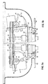
- Figure 1 is a perspective of a container and centrifuge in accordance with the invention.
- Figure 2 is a vertical cross section of a preferred embodiment of a container.
- Figures 3a and 3b are partial vertical cross sections ofthe centrifuge of figure 1.
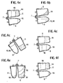
- FIGS. 4a through 4f arc schematic diagrams illustrating a preferred method of operation of the centrifuge of the invention.
- a centrifuge 2 is designed to receive a container 4 in accordance with the invention.
- the centrifuge is capable of subjecting the container to a series of steps that will be described in detail below.
- the container includes at least two chambers, 6 and 8.
- Chamber 6 is designed to receive a first fluid to be treated, such as blood.
- Chamber 8 is designed to receive fluids that have been decanted from chamber 6, such as a supernatant plasma resulting from centrifugation of blood in chamber 6.
- a preferred form of the container is shown in detail in figure 2.
- the container comprises three primary parts.
- a base part is preferably molded and includes the chambers 6 and 8 and a bridge 7, which connects the two chambers.
- the lid includes cup shaped extensions 12 and 14, each of which is centrally aligned with a respective one of the chambers 6 and 8.
- Extension 12 has a centrally located opening 13, while extension 14 has a centrally located opening 15.
- the openings receive syringe needles to permit fluids to be injected into the chambers or withdrawn therefrom.
- Membranes 16 and 17 cover the openings 13 and 15 to maintain sterility.
- the membranes are preferably heat sealed into the extensions 12 and 14 during construction by providing a cavity for receiving the membranes. After a membrane is inserted, the upper edges of the cavity are folded over and welded, e.g., ultrasonically, to retain the membrane.
- the lid also includes a bridge 7' that cooperates with bridge 7 in the base to form a fluid channel 18, connecting chambers 6 and 8. As shown, the bridge 7 extends above the tops of the chambers 6 and 8 to prevent communication between the chambers by "splashing.” Intentional fluid communication between the two chambers will be described in detail below.
- a separation disk 20 is preferably placed in chamber 6 near, but always above, the expected vertical position of the boundary between supernatant plasma and cellular components after a first centrifugation of a blood sample.
- the hematocrit is known to vary among individuals, and the exact amount of plasma that will result from a blood sample cannot be accurately specified without prior testing of the sample.
- disk 20 is located such that the plasma above the disk after centrifugation of a predetermined volume of blood is a predetermined amount of plasma.
- the upper surface of the disk 20 is tapered toward an edge, and the edge includes at least one groove 22 that allows fluid communication between the parts of the chamber 6 that are above and below the disk 20.
- a cylindrical support 24 is attached to the lower surface of the disk to set the location of the disk during assembly.
- a hollow tube 26 is provided to facilitate introduction of the blood sample to the portion of the chamber 6 that is below the disk 20.
- the tube 26 extends from just below the opening 13 through disk 20.
- a syringe needle inserted through opening 13 pierces membrane 16 and communicates with tube 26 to allow injection ofthe blood sample into the bottom ofthe chamber 6.
- the groove 22 permits vertical movement of the plasma and cellular components during centrifugation but retards movement of the cellular components during decanting.
- an air vent 27 is provided for chamber 8 to facilitate introduction and withdrawal of fluids.
- a container 4 is placed in a holder on the rotor of the centrifuge as indicated in figure 1.
- two such containers are preferably placed in the centrifuge in diametrically opposed positions.
- only one container may be used and a weight or "dummy" container used to balance the rotor.
- Figures 3a and 3b are partial cross sections of a preferred embodiment of a centrifuge showing the container locked in two different positions.
- a rotor shaft 28 is connected to a motor (not shown), which rotates the shaft.
- a rotor 30 is mounted to the shaft for rotation and has a frame 32 pivotally mounted to the rotor 30 at pivot connection 34.
- the top surface (not shown) of the frame 32 has two circular openings for receiving the chambers 6 and 8 whereby the container can be placed in the frame such that the contents ofthe container will be subjected to centrifugal forces as the rotor is rotated.
- a bias spring 35 ensures that the frame 32 will pivot to an upright position when centrifugation is terminated.
- the frame 32 may also be shaped to reduce wind resistance, as known in the art.
- a locking plate 36 is mounted coaxially with the shaft 28 for engaging the frame 32 to lock the container in desired orientations.
- the plate and the mechanism for controlling the positions of the plate may be the substantially the same as that shown in my previous United States patent number 5,178,602.
- an electromagnet 38 may be provided to control the position of the locking plate by action on a permanent magnet 40, which is attached to the locking plate.
- the electromagnet 38 and magnet 40 are positioned such that the locking plate can be placed in either of two positions.
- a first position shown in phantom lines
- the plate does not engage the frame 32, and the frame 32 is free to rotate about pivot 34.
- a second position shown in solid lincs at 36'
- the locking plate engages one of two parts of the frame 32 to hold it in one of two selected orientations.
- a lip of the plate engages a protuberance 42 on the frame 32 to lock the container in the orientation shown in figure 3a.
- the plate 36 engages an upper edge of the frame 32 to lock the container in the tilted position shown in figure 3a.
- the locking plate preferably rotates with the rotor whereby it can be moved to engage the frame during centrifugation of the contents of the container.
- a first step blood is introduced into chamber 6 ofthe container through opening 13.
- the blood has preferably been obtained from a patient, but it may be pooled or obtained from another.
- a precipitating agent 43 e.g., PEG, is then placed in chamber 8, preferably by injection through opening 15.
- the container with blood and precipitating agent are then placed in the centrifuge for automated operation.
- the container is allowed to swing freely as the blood is subjected to centrifugation.
- the cellular component 44 of the blood will be separated from the plasma component 46 in this step.
- the locking plate 36 is moved to a position shown at 36' whereby the container 4 is held in the position shown in figures 3b and 4b, and rotation of the rotor is stopped.
- the plasma component 46 flows through channel 18 by the force of gravity.
- the chamber is held in the position of figure 4b for preferably about 3 seconds, which is adequate to allow the plasma to drain by gravity into the chamber 8 but is not so long that the more viscous cellular component 44 drains into the chamber 8.
- the plasma 44 and precipitating agent 43 which was previously placed in chamber 8, are now both in chamber 8.
- the locking plate is lowered, and the rotor is caused to accelerate and decelerate alternately for 10-20 seconds, as illustrated in figure 4c.
- the precipitating agent causes the fibrinogen/Factor XIII to separate from the plasma, and this separation is assisted by centrifuging the contents ofthe container a second time. This second centrifugation may be for a period of about five minutes.
- a fibrinogen pellet 48 is, thus, formed in the bottom ofthe chamber 8, as illustrated in figure 4d. At this stage ofthe process, the plasma supernatant 46 remains in chamber 8.
- Plasma 46 is separated from the fibrinogen pellet 48 by stopping rotation of the centrifuge rotor to allow the container to pivot to the upright position shown in figures 3a and 4e.
- the locking plate 36 is then activated to lock the container in that orientation by engagement with protuberance 42, and the container is again rotated by the rotor for a period of about three to eight seconds. This rotation causes the supernatant plasma 46 to flow back through channel 18 and into chamber 6 by centrifugal draining, as illustrated in figure 4e.
- the fibrinogen pellet and plasma have now been separated.
- the container is subjected to another centrifugation illustrated in figure 4f for about fifteen seconds, whereby the fibrinogen pellet is forced into the bottom of the chamber 8.
- the fibrinogen pellet is preferably extracted from the container 8 by a syringe for further processing.
- the fibrinogen may be reconstituted and combined with thrombin to produce a sealant or an adhesive.
- the apparatus of the invention may be used for other automated processes.
- another technique for the separation of fibrinogen from blood in accordance with the structure of the invention uses cryoprecipitation.
- plasma is frozen to a temperature of about minus 20°C, thawed, and then centrifuged to separate the fibrinogen from plasma.
- the multiple-decanting apparatus of this invention may be used to automate cryoprecipitation by inclusion of a temperature control device 50 in thermal contact with the centrifuge.
- the temperature control device may comprise any of several known structures, including liquid nitrogen or liquid oxygen based devices and refrigeration devices.
- a sample of blood is placed in the first chamber 8, and the container is then placed in the centrifuge and subjected to a first centrifugation.
- the plasma is then drained into the second chamber 8, for example by gravity draining.
- the temperature control device is then activated first to freeze the plasma and then to allow the plasma to thaw.
- the thawed plasma is subjected to a second centrifugation, which separates fibrinogen from the remainder of the plasma.
- the supernatant plasma is then separated from the fibrinogen by draining it back into the first chamber, for example by centrifugal draining, whereby only fibrinogen remains in the second chamber.
- the container is then removed from the centrifuge, and the fibrinogen removed from it for use as described above.
- the freeze-thaw-centrifuge process may be carried out any number of times before the supernatant is drained back into the first chamber.
Abstract
Description
- This invention relates to the art of automatic centrifugation. In particular, the invention relates to apparatus and procedures using automatic, multiple decanting with centrifugation. In a preferred embodiment, an automated procedure separates fibrinogen from blood.
- The separation of components through centrifugation is well known. For example, in the medical field it is common to subject a sample of blood to centrifugation to produce a precipitate of cellular material and a supernatant of plasma. The plasma is then decanted to complete the separation ofthese components.
- United States patents 5,178,602 (Wells) and 5,047,004 (Wells) show an automated centrifuge, which includes structure for holding a centrifuge tube, after centrifugation, in a position that allows the supernatant to drain from the tube and into another container by gravity. The holding structure shown in these patents comprises a locking mechanism mounted for axial movement with respect to the axis of rotation of the centrifuge. An electromagnet that is easily controlled causes the axial movement.
- It is also known to decant a supernatant by the process of centrifugal draining. According to that process, a centrifuge rotates a centrifuge tube while the tube is held in a position such that the supernatant is drained from the tube by centrifugal forces.
- Fibrin sealants for treating wounds are known and are typically produced by combining a fibrinogen/Factor XIII component with bovine thrombin. When these are mixed, a fibrin tissue adhesive results, which is applied to the wound. Descriptions of compositions for use as tissue sealants are given in United States patents 5,292,362 and 5,209,776 (Bass et al.). The fibrinogen is obtained from plasma, either pooled or autologous, and cryoprecipitation is one known technique for separating fibrinogen from plasma. One cryoprecipitation technique is described in United States patent 5,318,524 and includes the centrifugation of thawing plasma to produce a precipitate containing fibrinogen/Factor XIII. Other techniques for producing fibrinogen/Factor XIII include inducing precipitation of the component by addition of such agents as Ammonium Sulfate or polyethylene glycol (PEG) to blood plasma.
- Several known chemical procedures include repeated steps of physical separation between two or more components. Separation based on density differences between the components is often by centrifugation, and the resulting supernatant is decanted to complete the separation. Each step provides an opportunity for error, which would be reduced by automation of the process.
- In accordance with the invention, chemical procedures requiring several centrifugation steps are automated, to reduce the time required by a clinician and eliminate the potential for errors. Apparatus in accordance with the invention includes a multiple-chamber container and a centrifuge designed to receive the container and subject its contents to predetermined centrifugation steps as well as gravity and centrifugal decanting ofthe supernatant.
- A preferred container in accordance with the invention includes first and second chambers separated by an intermediate wall. The first chamber is designed to receive a first liquid, such as human blood. The second chamber is located adjacent the first chamber, and the wall between the chambers is such that a supernatant in the first chamber will flow over the top of the wall and be drained into the second chamber by gravity when the container is held in the proper orientation. The supernatant in the second chamber may then be subjected to a second centrifugation. The container can also be held in a second position whereby a second supernatant is caused to flow back over the wall into the first chamber by centrifugal forces resulting from a second centrifugation.
- A centrifuge in accordance with the invention includes a rotatable support with a swinging frame for receiving the multiple-chamber container and means for locking the container in either of at least two positions for draining supernatant fluids from the chambers. Preferably, the locking means is an electro-magnetically operated disk mounted for movement axially with respect to the axis of rotation of the rotatable support. The centrifuge is preferably operated under the control of an electronic circuit, which may include a programmed array logic (PAL) or other circuitry, that causes the rotor to operate in accordance with a predetermined program and controls the locking means such that it locks the container in predetermined orientations in conjunction with operation of the rotor.
- While many different programs for operation of the centrifuge can be developed, depending on the desired results, a preferred operation is for the production of autologous fibrinogen. Prior techniques for production of fibrinogen require several distinct steps, each of which requires attention and provides an opportunity for error. These steps include separation of plasma from cellular components, treatment of the plasma with a precipitating agent, and separation of a fibrinogen precipitate "pellet" from the plasma. The separation of plasma from blood and the separation of the fibrinogen pellet from plasma typically require centrifugation first of the blood and then of the plasma, with addition of at least one precipitating agent between the steps. Thus, the production of fibrinogen in the prior art has been complex and error-prone.
- In accordance with this embodiment of the invention, a patient's blood is placed in the first chamber of the container, and a precipitation agent is placed in the second ofthe chambers. The container is then placed in the swinging frame of the centrifuge, and the control circuit is activated to initiate the operation of the centrifuge. The centrifuge first rotates the container for a time period that has been determined to be adequate for separating the cellular components from the supernatant plasma. During this time, the swinging frame will have rotated outwardly substantially due to centrifugal forces on the container. While the frame is in the outwardly rotated position, the locking means is activated to lock it there. The rotation ofthe support is then terminated. As the rotational velocity of the support decreases, the supernatant fluid, being no longer subject to the centrifugal forces, flows out of the first chamber and into the second chamber by gravity. The cellular component is more viscous and, thus, flows toward the second chamber at a rate less than that of the plasma, Preferably, however, a divider in the form of a disk is placed in the chamber to restrict the flow of the cellular components. The disk is at a depth that provides a predetermined volume of plasma, which is normally near the expected boundary between the supernatant and cellular components. After a period of time that has been determined to allow an adequate amount of the plasma to flow into the second chamber, the locking means is deactivated to release the container, whereby it assumes an upright position with the cellular component remaining in the first chamber and the plasma now in the second chamber. The rotatable support is then alternately activated and deactivated for short intervals to mix the plasma with the precipitating agent in the second chamber. Interaction between the precipitating agent and the plasma initiates precipitation of fibrinogen and Factor XIII from the plasma. The support is then again rotated to accelerate the precipitation of the fibrinogen/Factor XIII and to create a pellet in the bottom of the second chamber. As a final step, the locking means is again activated to lock the container in a position such that the supernatant resulting from precipitation of the fibrinogen is decanted by centrifugal draining into the first chamber. In this step, the container is held substantially upright, and the support is rotated to apply centrifugal forces to the supernatant, whereby it flows over the wall between the chambers and into the first chamber. The locking means is then inactivated, the container removed from the centrifuge, and the fibrinogen/Factor XIII removed from the second chamber for further processing. In a preferred embodiment, the fibrinogen/Factor XIII is then reconstituted, combined with thrombin, and applied to a paticnt to treat a wound.
- Figure 1 is a perspective of a container and centrifuge in accordance with the invention.
- Figure 2 is a vertical cross section of a preferred embodiment of a container.
- Figures 3a and 3b are partial vertical cross sections ofthe centrifuge of figure 1.
- Figures 4a through 4f arc schematic diagrams illustrating a preferred method of operation of the centrifuge of the invention.
- With reference to figures 1 and 2 of the drawings, a
centrifuge 2 is designed to receive acontainer 4 in accordance with the invention. The centrifuge is capable of subjecting the container to a series of steps that will be described in detail below. The container includes at least two chambers, 6 and 8.Chamber 6 is designed to receive a first fluid to be treated, such as blood.Chamber 8 is designed to receive fluids that have been decanted fromchamber 6, such as a supernatant plasma resulting from centrifugation of blood inchamber 6. - A preferred form of the container is shown in detail in figure 2. As shown, the container comprises three primary parts. A base part is preferably molded and includes the
chambers bridge 7, which connects the two chambers. A lid 11, also preferably molded, fits over the tops of the chambers to close them. The lid includes cup shapedextensions chambers Extension 12 has a centrally located opening 13, whileextension 14 has a centrally locatedopening 15. The openings receive syringe needles to permit fluids to be injected into the chambers or withdrawn therefrom.Membranes openings extensions - The lid also includes a bridge 7' that cooperates with
bridge 7 in the base to form a fluid channel 18, connectingchambers bridge 7 extends above the tops of thechambers - A
separation disk 20 is preferably placed inchamber 6 near, but always above, the expected vertical position of the boundary between supernatant plasma and cellular components after a first centrifugation of a blood sample. The hematocrit is known to vary among individuals, and the exact amount of plasma that will result from a blood sample cannot be accurately specified without prior testing of the sample. Thus,disk 20 is located such that the plasma above the disk after centrifugation of a predetermined volume of blood is a predetermined amount of plasma. The upper surface of thedisk 20 is tapered toward an edge, and the edge includes at least onegroove 22 that allows fluid communication between the parts of thechamber 6 that are above and below thedisk 20. - In a preferred embodiment, a
cylindrical support 24 is attached to the lower surface of the disk to set the location of the disk during assembly. - A
hollow tube 26 is provided to facilitate introduction of the blood sample to the portion of thechamber 6 that is below thedisk 20. Thetube 26 extends from just below theopening 13 throughdisk 20. Thus, a syringe needle inserted through opening 13 piercesmembrane 16 and communicates withtube 26 to allow injection ofthe blood sample into the bottom ofthechamber 6. Thegroove 22 permits vertical movement of the plasma and cellular components during centrifugation but retards movement of the cellular components during decanting. Also, anair vent 27 is provided forchamber 8 to facilitate introduction and withdrawal of fluids. - In use, a
container 4 is placed in a holder on the rotor of the centrifuge as indicated in figure 1. To balance the rotor, two such containers are preferably placed in the centrifuge in diametrically opposed positions. Of course, only one container may be used and a weight or "dummy" container used to balance the rotor. - Figures 3a and 3b are partial cross sections of a preferred embodiment of a centrifuge showing the container locked in two different positions. A
rotor shaft 28 is connected to a motor (not shown), which rotates the shaft. Arotor 30 is mounted to the shaft for rotation and has aframe 32 pivotally mounted to therotor 30 atpivot connection 34. The top surface (not shown) of theframe 32 has two circular openings for receiving thechambers bias spring 35 ensures that theframe 32 will pivot to an upright position when centrifugation is terminated. Theframe 32 may also be shaped to reduce wind resistance, as known in the art. - A locking
plate 36 is mounted coaxially with theshaft 28 for engaging theframe 32 to lock the container in desired orientations. The plate and the mechanism for controlling the positions of the plate may be the substantially the same as that shown in my previous United States patent number 5,178,602. For example, anelectromagnet 38 may be provided to control the position of the locking plate by action on apermanent magnet 40, which is attached to the locking plate. - Preferably, the
electromagnet 38 andmagnet 40 are positioned such that the locking plate can be placed in either of two positions. In a first position, shown in phantom lines, the plate does not engage theframe 32, and theframe 32 is free to rotate aboutpivot 34. In a second position, shown in solid lincs at 36', the locking plate engages one of two parts of theframe 32 to hold it in one of two selected orientations. In the position shown in figure 3a, a lip of the plate engages aprotuberance 42 on theframe 32 to lock the container in the orientation shown in figure 3a. In the position shown in figure 3b, theplate 36 engages an upper edge of theframe 32 to lock the container in the tilted position shown in figure 3a. The locking plate preferably rotates with the rotor whereby it can be moved to engage the frame during centrifugation of the contents of the container. - The operation of the centrifuge in a preferred embodiment of the invention will be described with regard to figures 4a through 4f. In a first step, blood is introduced into
chamber 6 ofthe container throughopening 13. The blood has preferably been obtained from a patient, but it may be pooled or obtained from another. A precipitatingagent 43, e.g., PEG, is then placed inchamber 8, preferably by injection throughopening 15. The container with blood and precipitating agent are then placed in the centrifuge for automated operation. - In the first step of automated operation, the container is allowed to swing freely as the blood is subjected to centrifugation. As illustrated in figure 4a, the
cellular component 44 of the blood will be separated from theplasma component 46 in this step. After a predetermined time period, e.g., five minutes, the lockingplate 36 is moved to a position shown at 36' whereby thecontainer 4 is held in the position shown in figures 3b and 4b, and rotation of the rotor is stopped. In this position, theplasma component 46 flows through channel 18 by the force of gravity. The chamber is held in the position of figure 4b for preferably about 3 seconds, which is adequate to allow the plasma to drain by gravity into thechamber 8 but is not so long that the more viscouscellular component 44 drains into thechamber 8. Theplasma 44 and precipitatingagent 43, which was previously placed inchamber 8, are now both inchamber 8. To provide complete mixing of these fluids, the locking plate is lowered, and the rotor is caused to accelerate and decelerate alternately for 10-20 seconds, as illustrated in figure 4c. The precipitating agent causes the fibrinogen/Factor XIII to separate from the plasma, and this separation is assisted by centrifuging the contents ofthe container a second time. This second centrifugation may be for a period of about five minutes. Afibrinogen pellet 48 is, thus, formed in the bottom ofthechamber 8, as illustrated in figure 4d. At this stage ofthe process, theplasma supernatant 46 remains inchamber 8. -
Plasma 46 is separated from thefibrinogen pellet 48 by stopping rotation of the centrifuge rotor to allow the container to pivot to the upright position shown in figures 3a and 4e. The lockingplate 36 is then activated to lock the container in that orientation by engagement withprotuberance 42, and the container is again rotated by the rotor for a period of about three to eight seconds. This rotation causes thesupernatant plasma 46 to flow back through channel 18 and intochamber 6 by centrifugal draining, as illustrated in figure 4e. Thus, the fibrinogen pellet and plasma have now been separated. As a final step, the container is subjected to another centrifugation illustrated in figure 4f for about fifteen seconds, whereby the fibrinogen pellet is forced into the bottom of thechamber 8. - The automated process for production of fibrinogen is at this point complete, and the fibrinogen pellet is preferably extracted from the
container 8 by a syringe for further processing. For example, the fibrinogen may be reconstituted and combined with thrombin to produce a sealant or an adhesive. - The apparatus of the invention may be used for other automated processes. For example, another technique for the separation of fibrinogen from blood in accordance with the structure of the invention uses cryoprecipitation. According to this technique, plasma is frozen to a temperature of about minus 20°C, thawed, and then centrifuged to separate the fibrinogen from plasma. The multiple-decanting apparatus of this invention may be used to automate cryoprecipitation by inclusion of a
temperature control device 50 in thermal contact with the centrifuge. The temperature control device may comprise any of several known structures, including liquid nitrogen or liquid oxygen based devices and refrigeration devices. - To effect automated cryoprecipitation, a sample of blood is placed in the
first chamber 8, and the container is then placed in the centrifuge and subjected to a first centrifugation. The plasma is then drained into thesecond chamber 8, for example by gravity draining. The temperature control device is then activated first to freeze the plasma and then to allow the plasma to thaw. The thawed plasma is subjected to a second centrifugation, which separates fibrinogen from the remainder of the plasma. The supernatant plasma is then separated from the fibrinogen by draining it back into the first chamber, for example by centrifugal draining, whereby only fibrinogen remains in the second chamber. The container is then removed from the centrifuge, and the fibrinogen removed from it for use as described above. Of course, the freeze-thaw-centrifuge process may be carried out any number of times before the supernatant is drained back into the first chamber. - Modifications within the scope of the appended claims will be apparent to those of skill in the art.
Claims (32)
- A centrifuge comprising a plurality of chambers for receiving substances to be centrifuged, means for rotating said chambers to subject said substances to centrifugation, and means for locking said chambers in first predetermined positions to allow a supernatant in a first of said chambers to drain into a second of said chambers.
- Apparatus according to claim 1 wherein said locking means is capable of locking said chambers in second predetermined positions to drain a supernatant in said second chamber to another of said chambers.
- Apparatus according to claim 2 wherein said first and second chambers are part of a container removable from said means for rotating.
- Apparatus according to claim 2 wherein said means for locking is capable of locking said chambers such that a supernatant in one of said chambers drains into another of said chambers by gravity draining.
- Apparatus according to claim 2 wherein said means for locking is capable of locking said chambers such that a supernatant in one of said chambers drains into another of said chambers by centrifugal draining.
- Apparatus according to claim 2 wherein said means for locking locks said first chamber such that a supernatant therein drains into said second chamber by gravity draining and locks said second chamber such that a supernatant therein drains into said first chamber by centrifugal draining.
- Apparatus according to claim 2 wherein said locking means comprises a movable plate and means for controlling the position of said plate.
- Apparatus according to claim 7 wherein means for controlling is electrical.
- Apparatus according to claim 8 wherein said means for controlling is magnetic.
- Apparatus according to claim 2 further comprising means for controlling said means for locking and said means for rotating to provide automatic multiple decanting by activating said means for rotating for a predetermined period of time, activating said means for locking to allow a supernatant in said first chamber to drain into said second chamber, activating said means for rotating a second time, and activating said means for locking a second time to allow a supernatant in said second chamber to drain into said first chamber.
- Apparatus according to claim 10 wherein said means for locking locks said first chamber such that a supernatant therein drains into said second chamber by gravity draining and locks said second chamber such that a supernatant therein drains into said first chamber by centrifugal draining.
- Apparatus according to claim 11 wherein said first and second chambers are part of a container removable from said means for rotating.
- Apparatus according to claim 1 further comprising means for controlling the temperature of the contents of said second chamber.
- Apparatus according to claim 13 wherein said means for controlling the temperature is capable of freezing said contents for cryoprecipitation.
- A method for automatic separation of components comprising placing first and second chambers in a centrifuge, subjecting said first chamber to centrifugation, locking said chambers in first positions such that a supernatant in said first chamber drains into said second chamber, and subjecting said second chamber to centrifugation.
- A method according to claim 15 further comprising locking said chambers such that a supematant in said second chamber drains into another of said chambers.
- A method according to claim 16 wherein said another of said chambers is said first chamber and said supernatant in said first chamber drains into said second chamber by gravity draining and said supernatant in said second chamber drains into said first chamber by centrifugal draining.
- A method according to claim 15 further comprising the step of freezing said supematant in said second chamber prior to said step of subjecting said second chamber to centrifugation.
- A method according to claim 18 further comprising thawing said supernatant and wherein said step of subjecting said second chamber to centrifugation is performed as said supernatant is thawing.
- A method according to claim 19 further comprising draining a second supernatant from said second chamber to said first chamber.
- A method for separation of components of a substance comprising:placing a first substance in a first chamber of a container having at least two separate chambers in fluid communication with each other,rotating said container to centrifuge said first substance and separate said first substance into a first component and a second component,locking said container in a position that allows said first component to flow into a second chamber of said container, androtating said container again to centrifuge said first component to produce a third component and a fourth component.
- A method according to claim 20 wherein said first component flows into said second chamber by gravity.
- A method according to claim 20 further comprising the step of locking said container in a position that allows said third component to flow to said first chamber.
- A method according to claim 23 further comprising the step of centrifugally draining said third component by rotating said container while locking said container in said position that allows said third component to flow to said first chamber.
- A method according to claim 24 wherein said first substance contains blood, said first component contains plasma, and said fourth component contains fibrinogen.
- A method according to claim 25 wherein said second chamber is supplied with a precipitating agent prior to said step of rotating said container to centrifuge said first substance.
- A method according to claim 26 wherein said precipitating agent is PEG.
- Apparatus for separation of a precipitate from a liquid comprising first and second adjacent chambers, wherein said first chamber is located with respect to said second chamber such that a supernatant in said first chamber drains by gravity into said second chamber when said first and second chambers are held in a first orientation and a second supernatant in said second chamber drains from said second chamber into said first chamber by centrifugal draining when said first and second chambers are held in a second orientation and subjected to centrifugation.
- Apparatus according to claim 28 wherein said first and second chambers are joined by a wall that forms a fluid flow path between said first and second chambers.
- Apparatus according to claim 29 further comprising divider means for dividing said first chamber into two parts, said divider means being located near the expected location of the interface between said first and second components.
- Apparatus according to claim 28 further comprising a covering on said first and second chambers for preventing spillage of the contents of said chambers while allowing a syringe to inject fluids into or remove fluids from said chambers.
- Apparatus according to claim 28 in combination with a centrifuge for subjecting said liquid to centrifugation, locking said chambers in said first orientation to allow said first supernatant to drain into said second chamber, and locking said chambers in said second orientation while rotating said chambers to provide said centrifugal draining.
Applications Claiming Priority (2)
| Application Number | Priority Date | Filing Date | Title |
|---|---|---|---|
| US08/435,662 US5707331A (en) | 1995-05-05 | 1995-05-05 | Automatic multiple-decanting centrifuge |
| US435662 | 1995-05-05 |
Publications (2)
| Publication Number | Publication Date |
|---|---|
| EP0740964A1 true EP0740964A1 (en) | 1996-11-06 |
| EP0740964B1 EP0740964B1 (en) | 2001-12-12 |
Family
ID=23729282
Family Applications (1)
| Application Number | Title | Priority Date | Filing Date |
|---|---|---|---|
| EP96303029A Expired - Lifetime EP0740964B1 (en) | 1995-05-05 | 1996-04-30 | Automatic multiple-decanting centrifuge |
Country Status (12)
| Country | Link |
|---|---|
| US (3) | US5707331A (en) |
| EP (1) | EP0740964B1 (en) |
| JP (4) | JP4673946B2 (en) |
| KR (1) | KR100435264B1 (en) |
| CN (1) | CN1082840C (en) |
| AT (1) | ATE210506T1 (en) |
| AU (1) | AU706177B2 (en) |
| CA (1) | CA2175397C (en) |
| DE (1) | DE69617793T2 (en) |
| DK (1) | DK0740964T3 (en) |
| ES (1) | ES2171612T3 (en) |
| PT (1) | PT740964E (en) |
Cited By (5)
| Publication number | Priority date | Publication date | Assignee | Title |
|---|---|---|---|---|
| WO2001008806A1 (en) * | 1999-08-02 | 2001-02-08 | Genomic S.A. | Equipment for automatic extraction of nucleic acids |
| US6716187B1 (en) | 1999-07-08 | 2004-04-06 | Implant Innovations, Inc. | Platelet concentration syringe kit |
| EP1549552A1 (en) * | 2002-09-19 | 2005-07-06 | Harvest Technologies Corporation | Sterile disposable unit |
| WO2010118979A1 (en) | 2009-04-07 | 2010-10-21 | Velin-Pharma A/S | Method and device for treatment of conditions associated with inflammation or undesirable activation of the immune system |
| WO2011029903A1 (en) | 2009-09-10 | 2011-03-17 | Flemming Velin | Method for the preparation of micro-rna and its therapeutic application |
Families Citing this family (100)
| Publication number | Priority date | Publication date | Assignee | Title |
|---|---|---|---|---|
| US7033339B1 (en) * | 1998-05-29 | 2006-04-25 | Becton Dickinson And Company (Part Interest) | Self sealing luer receiving stopcock |
| US5707331A (en) * | 1995-05-05 | 1998-01-13 | John R. Wells | Automatic multiple-decanting centrifuge |
| JPH1015436A (en) * | 1996-07-09 | 1998-01-20 | Tomy Seiko:Kk | Centrifugal separation method and centrifugal separator |
| US20040092451A1 (en) * | 1997-10-17 | 2004-05-13 | Lou Blasetti | Precipitation of growth-factor-enriched fibrinogen concentrate from platelet rich plasma |
| CA2306629A1 (en) * | 1997-10-17 | 1999-04-29 | Harvest Technologies Corporation | Precipitation of growth-factor-enriched fibrinogen concentrate from platelet rich plasma |
| US6234948B1 (en) * | 1997-10-27 | 2001-05-22 | Michael Yavilevich | Combined centrifugation assembly |
| DE69931899T8 (en) | 1998-03-11 | 2008-09-04 | Harvest Technologies Corp., Norwell | DEVICE FOR STERILE TRANSFER OF LIQUIDS |
| US6846460B1 (en) | 1999-01-29 | 2005-01-25 | Illumina, Inc. | Apparatus and method for separation of liquid phases of different density and for fluorous phase organic syntheses |
| WO2000061256A1 (en) | 1999-04-12 | 2000-10-19 | Harvest Technologies Corporation | Method and apparatus for producing platelet rich plasma and/or platelet concentrate |
| KR100358953B1 (en) * | 1999-10-29 | 2002-11-01 | 주식회사 비전과학 | Centrifugal separator for concentrating hemoblast |
| US7635390B1 (en) | 2000-01-14 | 2009-12-22 | Marctec, Llc | Joint replacement component having a modular articulating surface |
| US6190300B1 (en) * | 2000-03-10 | 2001-02-20 | Labnet International Inc. | Centrifuge rotor adapted for use with centrifuge tube strips |
| US20020104808A1 (en) * | 2000-06-30 | 2002-08-08 | Lou Blasetti | Method and apparatus for producing platelet rich plasma and/or platelet concentrate |
| US6503457B1 (en) | 2000-04-14 | 2003-01-07 | Discovery Partners International, Inc. | Container and method for high volume treatment of samples on solid supports |
| US6824738B1 (en) * | 2000-04-14 | 2004-11-30 | Discovery Partners International, Inc. | System and method for treatment of samples on solid supports |
| US6432365B1 (en) * | 2000-04-14 | 2002-08-13 | Discovery Partners International, Inc. | System and method for dispensing solution to a multi-well container |
| ES2298234T3 (en) * | 2000-04-28 | 2008-05-16 | Harvest Technologies Corporation | BLOOD COMPONENTS SEPARATING DISK. |
| JP3840888B2 (en) * | 2000-09-18 | 2006-11-01 | 日立工機株式会社 | Centrifuge and its rotor |
| US20030091473A1 (en) * | 2001-02-08 | 2003-05-15 | Downs Robert Charles | Automated centrifuge and method of using same |
| CA2448415C (en) * | 2001-06-06 | 2013-04-09 | Perfusion Partners & Associates, Inc. | Centrifuge tube assembly |
| US6623959B2 (en) | 2001-06-13 | 2003-09-23 | Ethicon, Inc. | Devices and methods for cell harvesting |
| US7374678B2 (en) * | 2002-05-24 | 2008-05-20 | Biomet Biologics, Inc. | Apparatus and method for separating and concentrating fluids containing multiple components |
| US6905612B2 (en) * | 2003-03-21 | 2005-06-14 | Hanuman Llc | Plasma concentrate apparatus and method |
| US7832566B2 (en) | 2002-05-24 | 2010-11-16 | Biomet Biologics, Llc | Method and apparatus for separating and concentrating a component from a multi-component material including macroparticles |
| US20030205538A1 (en) * | 2002-05-03 | 2003-11-06 | Randel Dorian | Methods and apparatus for isolating platelets from blood |
| US7992725B2 (en) | 2002-05-03 | 2011-08-09 | Biomet Biologics, Llc | Buoy suspension fractionation system |
| US7845499B2 (en) | 2002-05-24 | 2010-12-07 | Biomet Biologics, Llc | Apparatus and method for separating and concentrating fluids containing multiple components |
| US20060278588A1 (en) | 2002-05-24 | 2006-12-14 | Woodell-May Jennifer E | Apparatus and method for separating and concentrating fluids containing multiple components |
| DE10392686T5 (en) * | 2002-05-24 | 2005-07-07 | Biomet Mfg. Corp., Warsaw | Apparatus and method for separating and concentrating liquids containing multiple components |
| CA2493734C (en) * | 2002-08-02 | 2009-09-08 | Harvest Technologies Corporation | Decanting centrifuge with vibration isolation |
| KR100689516B1 (en) * | 2004-09-15 | 2007-03-02 | 삼성전자주식회사 | Method and apparatus for indicating preferred layer information in multimedia broadcast/multicast system |
| US20060094865A1 (en) * | 2004-10-29 | 2006-05-04 | Kapur Terri A | Intraoperative method for isolating and concentrating autologous growth factors and for forming residual autologous growth factor compositions |
| PT1848473E (en) * | 2005-02-07 | 2013-08-28 | Hanuman Llc | Plasma concentrator device |
| US7442178B2 (en) | 2005-03-09 | 2008-10-28 | Jacques Chammas | Automated system and method for blood components separation and processing |
| US7694828B2 (en) | 2005-04-27 | 2010-04-13 | Biomet Manufacturing Corp. | Method and apparatus for producing autologous clotting components |
| JP5055282B2 (en) * | 2005-09-14 | 2012-10-24 | イルミナ インコーポレイテッド | Continuous polymer synthesizer |
| KR100684138B1 (en) | 2005-11-11 | 2007-02-20 | 주식회사 잉크테크 | Centrifugal saparator for removing residual ink in ink cartridge |
| US8567609B2 (en) | 2006-05-25 | 2013-10-29 | Biomet Biologics, Llc | Apparatus and method for separating and concentrating fluids containing multiple components |
| KR100772969B1 (en) * | 2006-06-08 | 2007-11-02 | 양현진 | Centrifuge and centrifuging method |
| KR100772970B1 (en) | 2006-06-30 | 2007-11-02 | 메디칸(주) | Centrifuge and centrifuging method |
| KR100767448B1 (en) * | 2006-06-30 | 2007-10-17 | 메디칸(주) | Centrifuge and centrifuging method |
| US8034014B2 (en) | 2007-03-06 | 2011-10-11 | Biomet Biologics, Llc | Angiogenesis initation and growth |
| JP5105925B2 (en) | 2007-03-26 | 2012-12-26 | 京セラメディカル株式会社 | Centrifugal device |
| US8328024B2 (en) | 2007-04-12 | 2012-12-11 | Hanuman, Llc | Buoy suspension fractionation system |
| JP5479319B2 (en) | 2007-04-12 | 2014-04-23 | バイオメット・バイオロジックス・リミテッド・ライアビリティ・カンパニー | Buoy suspension fractionation system |
| US20080269762A1 (en) * | 2007-04-25 | 2008-10-30 | Biomet Manufacturing Corp. | Method and device for repair of cartilage defects |
| US8348066B2 (en) * | 2007-12-07 | 2013-01-08 | Harvest Technologies Corporation | Floating disk for separating blood components |
| US8753690B2 (en) | 2008-02-27 | 2014-06-17 | Biomet Biologics, Llc | Methods and compositions for delivering interleukin-1 receptor antagonist |
| EP2567692B1 (en) * | 2008-02-27 | 2016-04-06 | Biomet Biologics, LLC | Use of a device for obtaining interleukin-1 receptor antagonist rich solutions |
| US8337711B2 (en) * | 2008-02-29 | 2012-12-25 | Biomet Biologics, Llc | System and process for separating a material |
| CA2762086C (en) * | 2008-08-22 | 2015-06-02 | Matthew R. Kyle | Fluid management devices and methods |
| US20100112696A1 (en) * | 2008-11-03 | 2010-05-06 | Baxter International Inc. | Apparatus And Methods For Processing Tissue To Release Cells |
| EP2189218A1 (en) * | 2008-11-12 | 2010-05-26 | F. Hoffmann-Roche AG | Multiwell plate lid separation |
| US8309343B2 (en) | 2008-12-01 | 2012-11-13 | Baxter International Inc. | Apparatus and method for processing biological material |
| US8177072B2 (en) | 2008-12-04 | 2012-05-15 | Thermogenesis Corp. | Apparatus and method for separating and isolating components of a biological fluid |
| US8187475B2 (en) | 2009-03-06 | 2012-05-29 | Biomet Biologics, Llc | Method and apparatus for producing autologous thrombin |
| US8313954B2 (en) * | 2009-04-03 | 2012-11-20 | Biomet Biologics, Llc | All-in-one means of separating blood components |
| CN102802804A (en) | 2009-05-01 | 2012-11-28 | 波士顿大学董事会 | Disposal Separator/concentrator Device And Method Of Use |
| KR101119955B1 (en) * | 2009-05-11 | 2012-03-15 | 주식회사 메디사랑 | thermostatic centrifuge for making fibrinogen |
| US9011800B2 (en) * | 2009-07-16 | 2015-04-21 | Biomet Biologics, Llc | Method and apparatus for separating biological materials |
| CA2772084C (en) | 2009-08-27 | 2016-10-18 | Biomet Biologics, Llc | Implantable device for production of interleukin-1 receptor antagonist |
| US20110052561A1 (en) * | 2009-08-27 | 2011-03-03 | Biomet Biologics,LLC | Osteolysis treatment |
| US8591391B2 (en) | 2010-04-12 | 2013-11-26 | Biomet Biologics, Llc | Method and apparatus for separating a material |
| US9101926B2 (en) * | 2010-08-21 | 2015-08-11 | Microaire Surgical Instruments, Llc | Method for separating a sample into density specific fractions |
| US9555171B2 (en) | 2010-09-30 | 2017-01-31 | Depuy Mitek, Llc | Methods and devices for collecting separate components of whole blood |
| US8317672B2 (en) | 2010-11-19 | 2012-11-27 | Kensey Nash Corporation | Centrifuge method and apparatus |
| US8870733B2 (en) | 2010-11-19 | 2014-10-28 | Kensey Nash Corporation | Centrifuge |
| US8556794B2 (en) | 2010-11-19 | 2013-10-15 | Kensey Nash Corporation | Centrifuge |
| US8469871B2 (en) | 2010-11-19 | 2013-06-25 | Kensey Nash Corporation | Centrifuge |
| US8394006B2 (en) | 2010-11-19 | 2013-03-12 | Kensey Nash Corporation | Centrifuge |
| US9011846B2 (en) | 2011-05-02 | 2015-04-21 | Biomet Biologics, Llc | Thrombin isolated from blood and blood fractions |
| DE102011077124A1 (en) * | 2011-06-07 | 2012-12-13 | Robert Bosch Gmbh | Cartridge, centrifuge and process |
| KR101197908B1 (en) * | 2011-10-31 | 2012-11-05 | 박현정 | A container for centrifugal separation |
| KR101197974B1 (en) * | 2011-11-01 | 2012-11-05 | 박현정 | A container for centrifugal separator capable of rapid centrifugal separation |
| US9440243B2 (en) | 2012-02-15 | 2016-09-13 | Microaire Surgical Instruments, Llc | Apparatus for centrifugation and methods therefore |
| US9642956B2 (en) | 2012-08-27 | 2017-05-09 | Biomet Biologics, Llc | Apparatus and method for separating and concentrating fluids containing multiple components |
| KR20150095759A (en) * | 2012-12-13 | 2015-08-21 | 가부시끼가이샤 제이엠에스 | Device for separating/housing blood components and method for preparing platelet-rich plasma |
| US9895418B2 (en) | 2013-03-15 | 2018-02-20 | Biomet Biologics, Llc | Treatment of peripheral vascular disease using protein solutions |
| US10208095B2 (en) | 2013-03-15 | 2019-02-19 | Biomet Manufacturing, Llc | Methods for making cytokine compositions from tissues using non-centrifugal methods |
| US9878011B2 (en) | 2013-03-15 | 2018-01-30 | Biomet Biologics, Llc | Treatment of inflammatory respiratory disease using biological solutions |
| US10143725B2 (en) | 2013-03-15 | 2018-12-04 | Biomet Biologics, Llc | Treatment of pain using protein solutions |
| US20140271589A1 (en) | 2013-03-15 | 2014-09-18 | Biomet Biologics, Llc | Treatment of collagen defects using protein solutions |
| US9950035B2 (en) | 2013-03-15 | 2018-04-24 | Biomet Biologics, Llc | Methods and non-immunogenic compositions for treating inflammatory disorders |
| US9758806B2 (en) | 2013-03-15 | 2017-09-12 | Biomet Biologics, Llc | Acellular compositions for treating inflammatory disorders |
| WO2014160781A1 (en) | 2013-03-26 | 2014-10-02 | Alliance Partners Llc | Biological fluids concentration assembly |
| CN106132555B (en) * | 2013-11-11 | 2019-07-26 | 生命科技股份有限公司 | Rotor stack and its application method |
| US9833474B2 (en) | 2013-11-26 | 2017-12-05 | Biomet Biologies, LLC | Methods of mediating macrophage phenotypes |
| WO2015117007A1 (en) | 2014-01-31 | 2015-08-06 | Dsm Ip Assets B.V. | Adipose tissue centrifuge and method of use |
| US9550028B2 (en) | 2014-05-06 | 2017-01-24 | Biomet Biologics, LLC. | Single step desiccating bead-in-syringe concentrating device |
| CA2959342A1 (en) | 2014-08-25 | 2016-03-03 | Reviticell Holdings, Llc | Modular single-use kits and methods for preparation of biological material |
| EP3212332B1 (en) | 2014-10-28 | 2021-02-24 | Arteriocyte Medical Systems, Inc. | Centrifuge tube comprising a floating buoy, and methods for using the same |
| US10441635B2 (en) | 2014-11-10 | 2019-10-15 | Biomet Biologics, Llc | Methods of treating pain using protein solutions |
| US9763800B2 (en) | 2015-03-18 | 2017-09-19 | Biomet C. V. | Implant configured for hammertoe and small bone fixation |
| US10501715B1 (en) | 2015-09-11 | 2019-12-10 | Mark H. Widick | System for the formation of fibrin foam |
| KR101894966B1 (en) | 2017-03-30 | 2018-09-04 | 신현순 | A container for centrifugal separator |
| EP3421134B1 (en) * | 2017-06-27 | 2020-09-30 | Tecan Trading Ag | Centrifugal processing unit |
| EP3421133B1 (en) * | 2017-06-27 | 2020-09-16 | Tecan Trading Ag | Centrifugal processing unit |
| US11272996B2 (en) | 2019-10-04 | 2022-03-15 | Reviticell Holdings, Inc. | Methods and devices for performing sequential procedures utilizing a standardized system |
| KR102453356B1 (en) | 2019-12-02 | 2022-10-11 | 고려대학교 산학협력단 | Microchip for sample concentration and sample concentration method using the same |
| KR20230128849A (en) | 2022-02-28 | 2023-09-05 | (주)옵토레인 | Catridge for device of centrifugal separation |
Citations (8)
| Publication number | Priority date | Publication date | Assignee | Title |
|---|---|---|---|---|
| US3190546A (en) * | 1959-03-27 | 1965-06-22 | Raccuglia Giovanni | Method and apparatus for separating liquid mixtures |
| US3420437A (en) * | 1967-02-15 | 1969-01-07 | Sorvall Inc Ivan | Cell washing centrifuge |
| US3586484A (en) * | 1969-05-23 | 1971-06-22 | Atomic Energy Commission | Multistation analytical photometer and method of use |
| US3953172A (en) * | 1974-05-10 | 1976-04-27 | Union Carbide Corporation | Method and apparatus for assaying liquid materials |
| US4066407A (en) * | 1976-12-16 | 1978-01-03 | Vincent Lupica | Body fluid testing system and process |
| US4714457A (en) * | 1986-09-15 | 1987-12-22 | Robert Alterbaum | Method and apparatus for use in preparation of fibrinogen from a patient's blood |
| US5178602A (en) * | 1990-02-07 | 1993-01-12 | Wells John R | Automatic decanting centrifuge |
| DE4323844A1 (en) * | 1993-07-16 | 1995-01-19 | Hettich Andreas Fa | Washing centrifuge |
Family Cites Families (44)
| Publication number | Priority date | Publication date | Assignee | Title |
|---|---|---|---|---|
| CA461698A (en) * | 1949-12-13 | Langstadt Julius | Compartmented receptacle | |
| US1722396A (en) * | 1928-02-13 | 1929-07-30 | Winfield S Reiber | Milk bottle |
| FR936560A (en) * | 1946-11-21 | 1948-07-23 | Csf | Sealed oil tank for high voltage devices mounted on fighter planes |
| GB958615A (en) * | 1962-02-19 | 1964-05-21 | Eschmann Bros & Walsh Ltd | Container for surgical instruments and closure for the container |
| US3221741A (en) * | 1962-06-18 | 1965-12-07 | Veen Harry H Le | Container for collecting and storing blood having anticoagulant means therein |
| US3164186A (en) * | 1962-07-13 | 1965-01-05 | Eberhard E H Weber | Plastic container |
| US3228444A (en) * | 1964-11-18 | 1966-01-11 | Eberhard E H Weber | Specimen container |
| US3586848A (en) * | 1968-11-26 | 1971-06-22 | William H Loftis | Illuminated clock |
| US3642163A (en) * | 1970-03-20 | 1972-02-15 | Lorrell C Mcfarland | Multitubular pressure tank |
| US3605829A (en) * | 1970-04-29 | 1971-09-20 | Becton Dickinson Co | Blood handling machine |
| US3727788A (en) * | 1970-12-09 | 1973-04-17 | Medical Dev Corp | Fluid container structure having mutually cooperable port connections |
| JPS4711663U (en) * | 1971-03-05 | 1972-10-12 | ||
| US3774455A (en) * | 1971-12-22 | 1973-11-27 | D Seidler | Urine testing apparatus |
| BE793544A (en) * | 1972-01-31 | 1973-04-16 | American Hospital Supply Corp | CENTRIFUGE |
| IT954219B (en) * | 1972-04-21 | 1973-08-30 | Tomasello M | URINE CONTAINER INTENDED FOR ANALYSIS |
| JPS4969292U (en) * | 1972-09-27 | 1974-06-17 | ||
| JPS49133965A (en) * | 1972-11-03 | 1974-12-23 | ||
| US3877634A (en) * | 1973-05-25 | 1975-04-15 | Du Pont | Cell washing centrifuge apparatus and system |
| US3851817A (en) * | 1973-05-29 | 1974-12-03 | E Buck | Method and means for centrifuging chilled blood samples |
| JPS50154581U (en) * | 1974-06-07 | 1975-12-22 | ||
| IT1028403B (en) * | 1975-01-16 | 1979-01-30 | Crippa Egidia | CONTAINER WITH EXTERNAL TUBE FOR ANALYSIS OF URINE AND OTHER ACID LIQUIDS |
| JPS521662A (en) * | 1975-06-24 | 1977-01-07 | Tomoyuki Otake | Counter-current device for centrifugal transfer |
| US3951334A (en) * | 1975-07-07 | 1976-04-20 | E. I. Du Pont De Nemours And Company | Method and apparatus for automatically positioning centrifuge tubes |
| US4150089A (en) * | 1977-09-06 | 1979-04-17 | Linet Michael S | Multi-chamber test tube |
| JPS5828529B2 (en) * | 1978-11-03 | 1983-06-16 | 株式会社日本クリンエンジン研究所 | Portable constant volume ratio mixing container |
| US4285463A (en) * | 1979-11-01 | 1981-08-25 | American Hospital Supply Corporation | Decanting centrifuge |
| JPS56118669A (en) * | 1980-02-25 | 1981-09-17 | Sekisui Chem Co Ltd | Blood serum separator |
| US4431423A (en) * | 1982-03-10 | 1984-02-14 | E. I. Du Pont De Nemours & Co. | Cell washing apparatus having radially inwardly directed retaining arms |
| JPS59210343A (en) * | 1983-05-14 | 1984-11-29 | Kokusan Enshinki Kk | Automatic separation and collecting method of serum and its apparatus |
| JPS61132866A (en) * | 1984-12-03 | 1986-06-20 | Mitsubishi Chem Ind Ltd | Tubular vessel made of synthetic resin |
| US4932546A (en) * | 1989-03-16 | 1990-06-12 | Buttes Gas & Oil Co. | Pressure vessel |
| US5045047A (en) * | 1989-07-17 | 1991-09-03 | Zymark Corporation | Automated centrifuge |
| US5199937A (en) * | 1989-08-24 | 1993-04-06 | Kurashiki Boseki Kabushiki Kaisha | Centrifugal separator |
| US5318524A (en) * | 1990-01-03 | 1994-06-07 | Cryolife, Inc. | Fibrin sealant delivery kit |
| US5030215A (en) * | 1990-01-03 | 1991-07-09 | Cryolife, Inc. | Preparation of fibrinogen/factor XIII precipitate |
| US5047004A (en) * | 1990-02-07 | 1991-09-10 | Wells John R | Automatic decanting centrifuge |
| JPH03270701A (en) * | 1990-03-19 | 1991-12-02 | Terumo Corp | Centrifugal separation tube and separation of cell |
| US5209776A (en) * | 1990-07-27 | 1993-05-11 | The Trustees Of Columbia University In The City Of New York | Tissue bonding and sealing composition and method of using the same |
| US5292362A (en) * | 1990-07-27 | 1994-03-08 | The Trustees Of Columbia University In The City Of New York | Tissue bonding and sealing composition and method of using the same |
| IL100828A (en) * | 1992-01-31 | 2002-05-23 | Novamed Ltd | Method and means for density gradient centrifugation |
| US5447245A (en) * | 1993-07-20 | 1995-09-05 | Merhar; Richard D. | Graduated proportioning and mixing container |
| JPH0780058A (en) * | 1993-09-20 | 1995-03-28 | Terumo Corp | Bag connector and method for separating and transporting component |
| US5503284A (en) * | 1994-12-23 | 1996-04-02 | Li; Hofman Y. | Single continuous wall, multi-chamber container |
| US5707331A (en) * | 1995-05-05 | 1998-01-13 | John R. Wells | Automatic multiple-decanting centrifuge |
-
1995
- 1995-05-05 US US08/435,662 patent/US5707331A/en not_active Ceased
-
1996
- 1996-04-30 EP EP96303029A patent/EP0740964B1/en not_active Expired - Lifetime
- 1996-04-30 CA CA002175397A patent/CA2175397C/en not_active Expired - Fee Related
- 1996-04-30 ES ES96303029T patent/ES2171612T3/en not_active Expired - Lifetime
- 1996-04-30 DK DK96303029T patent/DK0740964T3/en active
- 1996-04-30 AT AT96303029T patent/ATE210506T1/en active
- 1996-04-30 PT PT96303029T patent/PT740964E/en unknown
- 1996-04-30 DE DE69617793T patent/DE69617793T2/en not_active Expired - Lifetime
- 1996-05-02 AU AU52031/96A patent/AU706177B2/en not_active Ceased
- 1996-05-04 KR KR1019960014545A patent/KR100435264B1/en not_active IP Right Cessation
- 1996-05-06 CN CN96104944A patent/CN1082840C/en not_active Expired - Fee Related
- 1996-05-07 JP JP11280496A patent/JP4673946B2/en not_active Expired - Fee Related
-
1997
- 1997-10-06 US US08/944,179 patent/US5895346A/en not_active Ceased
-
2000
- 2000-01-13 US US09/482,653 patent/USRE38757E1/en not_active Expired - Lifetime
-
2006
- 2006-07-12 JP JP2006192125A patent/JP2006315001A/en not_active Withdrawn
-
2010
- 2010-10-18 JP JP2010234089A patent/JP5641867B2/en not_active Expired - Lifetime
-
2013
- 2013-07-08 JP JP2013142570A patent/JP2013240793A/en not_active Withdrawn
Patent Citations (8)
| Publication number | Priority date | Publication date | Assignee | Title |
|---|---|---|---|---|
| US3190546A (en) * | 1959-03-27 | 1965-06-22 | Raccuglia Giovanni | Method and apparatus for separating liquid mixtures |
| US3420437A (en) * | 1967-02-15 | 1969-01-07 | Sorvall Inc Ivan | Cell washing centrifuge |
| US3586484A (en) * | 1969-05-23 | 1971-06-22 | Atomic Energy Commission | Multistation analytical photometer and method of use |
| US3953172A (en) * | 1974-05-10 | 1976-04-27 | Union Carbide Corporation | Method and apparatus for assaying liquid materials |
| US4066407A (en) * | 1976-12-16 | 1978-01-03 | Vincent Lupica | Body fluid testing system and process |
| US4714457A (en) * | 1986-09-15 | 1987-12-22 | Robert Alterbaum | Method and apparatus for use in preparation of fibrinogen from a patient's blood |
| US5178602A (en) * | 1990-02-07 | 1993-01-12 | Wells John R | Automatic decanting centrifuge |
| DE4323844A1 (en) * | 1993-07-16 | 1995-01-19 | Hettich Andreas Fa | Washing centrifuge |
Cited By (9)
| Publication number | Priority date | Publication date | Assignee | Title |
|---|---|---|---|---|
| US6716187B1 (en) | 1999-07-08 | 2004-04-06 | Implant Innovations, Inc. | Platelet concentration syringe kit |
| WO2001008806A1 (en) * | 1999-08-02 | 2001-02-08 | Genomic S.A. | Equipment for automatic extraction of nucleic acids |
| FR2797202A1 (en) * | 1999-08-02 | 2001-02-09 | Genomic | EQUIPMENT FOR THE AUTOMATIC EXTRACTION OF NUCLEIC ACIDS |
| US6837843B2 (en) | 1999-08-02 | 2005-01-04 | Genomic S.A. | Equipment for automatic extraction of nucleic acids |
| EP1549552A1 (en) * | 2002-09-19 | 2005-07-06 | Harvest Technologies Corporation | Sterile disposable unit |
| EP1549552A4 (en) * | 2002-09-19 | 2010-11-24 | Harvest Technologies Corp | Sterile disposable unit |
| WO2010118979A1 (en) | 2009-04-07 | 2010-10-21 | Velin-Pharma A/S | Method and device for treatment of conditions associated with inflammation or undesirable activation of the immune system |
| WO2011029903A1 (en) | 2009-09-10 | 2011-03-17 | Flemming Velin | Method for the preparation of micro-rna and its therapeutic application |
| US9078914B2 (en) | 2009-09-10 | 2015-07-14 | Velin-Pharma A/S | Method for the preparation of micro-RNA and its therapeutic application |
Also Published As
| Publication number | Publication date |
|---|---|
| CA2175397C (en) | 2007-02-20 |
| US5895346A (en) | 1999-04-20 |
| DE69617793D1 (en) | 2002-01-24 |
| EP0740964B1 (en) | 2001-12-12 |
| DK0740964T3 (en) | 2002-04-15 |
| ES2171612T3 (en) | 2002-09-16 |
| JP2011045883A (en) | 2011-03-10 |
| JP2013240793A (en) | 2013-12-05 |
| US5707331A (en) | 1998-01-13 |
| KR960040452A (en) | 1996-12-17 |
| JPH09103707A (en) | 1997-04-22 |
| CA2175397A1 (en) | 1996-11-06 |
| AU5203196A (en) | 1996-11-14 |
| JP4673946B2 (en) | 2011-04-20 |
| DE69617793T2 (en) | 2002-08-14 |
| JP5641867B2 (en) | 2014-12-17 |
| AU706177B2 (en) | 1999-06-10 |
| CN1135938A (en) | 1996-11-20 |
| CN1082840C (en) | 2002-04-17 |
| ATE210506T1 (en) | 2001-12-15 |
| JP2006315001A (en) | 2006-11-24 |
| PT740964E (en) | 2002-06-28 |
| USRE38757E1 (en) | 2005-07-12 |
| KR100435264B1 (en) | 2004-07-31 |
Similar Documents
| Publication | Publication Date | Title |
|---|---|---|
| US5895346A (en) | Automatic multiple-decanting centrifuge | |
| USRE38730E1 (en) | Automatic multiple-decanting centrifuge and method of treating physiological fluids | |
| CA2334887C (en) | Method and apparatus for producing platelet rich plasma and/or platelet concentrate | |
| US20140311988A1 (en) | Method and apparatus for producing platelet rich plasma and/or platelet concentrate | |
| US5858253A (en) | Blood separation process | |
| JP5183883B2 (en) | Method and apparatus for generating an autologous coagulation component | |
| US4846974A (en) | Centrifuge system and fluid container therefor | |
| US4981585A (en) | Centrifuge system and fluid container therefor | |
| US20060261014A1 (en) | Precipitation of growth-factor-enriched fibrinogen concentrate from platelet rich plasma | |
| US6946079B1 (en) | Centrifugal filtration method for separating fibrin monomer from blood | |
| CN1113656C (en) | Precipitation of growth-factor-enriched fibrinogen concentrate from platelet rich plasma | |
| CN108940613A (en) | Blood sample separates centrifuge and its separation method | |
| JP5258765B2 (en) | Apparatus and method for preparing platelet-enriched plasma and concentrates thereof | |
| WO2014126545A1 (en) | A centrifuge structured for use in making platelet-rich fibrin | |
| JPWO2002042430A1 (en) | Nucleic acid extraction device |
Legal Events
| Date | Code | Title | Description |
|---|---|---|---|
| PUAI | Public reference made under article 153(3) epc to a published international application that has entered the european phase |
Free format text: ORIGINAL CODE: 0009012 |
|
| AK | Designated contracting states |
Kind code of ref document: A1 Designated state(s): AT BE CH DE DK ES FI FR GB GR IE IT LI LU MC NL PT SE |
|
| 17P | Request for examination filed |
Effective date: 19970509 |
|
| 17Q | First examination report despatched |
Effective date: 19990921 |
|
| GRAG | Despatch of communication of intention to grant |
Free format text: ORIGINAL CODE: EPIDOS AGRA |
|
| GRAG | Despatch of communication of intention to grant |
Free format text: ORIGINAL CODE: EPIDOS AGRA |
|
| GRAH | Despatch of communication of intention to grant a patent |
Free format text: ORIGINAL CODE: EPIDOS IGRA |
|
| GRAH | Despatch of communication of intention to grant a patent |
Free format text: ORIGINAL CODE: EPIDOS IGRA |
|
| GRAA | (expected) grant |
Free format text: ORIGINAL CODE: 0009210 |
|
| AK | Designated contracting states |
Kind code of ref document: B1 Designated state(s): AT BE CH DE DK ES FI FR GB GR IE IT LI LU MC NL PT SE |
|
| PG25 | Lapsed in a contracting state [announced via postgrant information from national office to epo] |
Ref country code: GR Free format text: LAPSE BECAUSE OF FAILURE TO SUBMIT A TRANSLATION OF THE DESCRIPTION OR TO PAY THE FEE WITHIN THE PRESCRIBED TIME-LIMIT Effective date: 20011212 |
|
| REF | Corresponds to: |
Ref document number: 210506 Country of ref document: AT Date of ref document: 20011215 Kind code of ref document: T |
|
| REG | Reference to a national code |
Ref country code: CH Ref legal event code: EP |
|
| REG | Reference to a national code |
Ref country code: GB Ref legal event code: IF02 |
|
| RAP2 | Party data changed (patent owner data changed or rights of a patent transferred) |
Owner name: HARVEST TECHNOLOGIES CORPORATION |
|
| REG | Reference to a national code |
Ref country code: IE Ref legal event code: FG4D |
|
| REF | Corresponds to: |
Ref document number: 69617793 Country of ref document: DE Date of ref document: 20020124 |
|
| NLT2 | Nl: modifications (of names), taken from the european patent patent bulletin |
Owner name: HARVEST TECHNOLOGIES CORPORATION |
|
| REG | Reference to a national code |
Ref country code: DK Ref legal event code: T3 |
|
| PG25 | Lapsed in a contracting state [announced via postgrant information from national office to epo] |
Ref country code: MC Free format text: LAPSE BECAUSE OF NON-PAYMENT OF DUE FEES Effective date: 20020430 Ref country code: LU Free format text: LAPSE BECAUSE OF NON-PAYMENT OF DUE FEES Effective date: 20020430 |
|
| REG | Reference to a national code |
Ref country code: CH Ref legal event code: PFA Free format text: HARVEST TECHNOLOGIES CORPORATION,77 ACCORD PARK DRIVE D-7,NORWELL, MA 02061 (US) TRANSFER- HARVEST TECHNOLOGIES CORPORATION,40 GRISSOM ROAD, SUITE, NO. 100,PLYMOUTH, MASSACHUSETTS 02360 (US) Ref country code: CH Ref legal event code: NV Representative=s name: DR. R.C. SALGO EUROPEAN PATENT ATTORNEY |
|
| ET | Fr: translation filed | ||
| REG | Reference to a national code |
Ref country code: PT Ref legal event code: SC4A Free format text: AVAILABILITY OF NATIONAL TRANSLATION Effective date: 20020312 |
|
| REG | Reference to a national code |
Ref country code: ES Ref legal event code: FG2A Ref document number: 2171612 Country of ref document: ES Kind code of ref document: T3 |
|
| PLBE | No opposition filed within time limit |
Free format text: ORIGINAL CODE: 0009261 |
|
| STAA | Information on the status of an ep patent application or granted ep patent |
Free format text: STATUS: NO OPPOSITION FILED WITHIN TIME LIMIT |
|
| 26N | No opposition filed | ||
| REG | Reference to a national code |
Ref country code: GB Ref legal event code: 732E |
|
| PGFP | Annual fee paid to national office [announced via postgrant information from national office to epo] |
Ref country code: AT Payment date: 20120327 Year of fee payment: 17 |
|
| PGFP | Annual fee paid to national office [announced via postgrant information from national office to epo] |
Ref country code: DK Payment date: 20130325 Year of fee payment: 18 |
|
| PGFP | Annual fee paid to national office [announced via postgrant information from national office to epo] |
Ref country code: PT Payment date: 20130327 Year of fee payment: 18 |
|
| PGFP | Annual fee paid to national office [announced via postgrant information from national office to epo] |
Ref country code: SE Payment date: 20130405 Year of fee payment: 18 Ref country code: BE Payment date: 20130424 Year of fee payment: 18 Ref country code: IE Payment date: 20130418 Year of fee payment: 18 Ref country code: CH Payment date: 20130426 Year of fee payment: 18 |
|
| PGFP | Annual fee paid to national office [announced via postgrant information from national office to epo] |
Ref country code: FI Payment date: 20130405 Year of fee payment: 18 Ref country code: FR Payment date: 20130417 Year of fee payment: 18 Ref country code: NL Payment date: 20130409 Year of fee payment: 18 |
|
| PGFP | Annual fee paid to national office [announced via postgrant information from national office to epo] |
Ref country code: ES Payment date: 20140428 Year of fee payment: 19 Ref country code: IT Payment date: 20140414 Year of fee payment: 19 |
|
| REG | Reference to a national code |
Ref country code: PT Ref legal event code: MM4A Free format text: LAPSE DUE TO NON-PAYMENT OF FEES Effective date: 20141031 |
|
| REG | Reference to a national code |
Ref country code: DK Ref legal event code: EBP Effective date: 20140430 |
|
| REG | Reference to a national code |
Ref country code: NL Ref legal event code: V1 Effective date: 20141101 |
|
| REG | Reference to a national code |
Ref country code: CH Ref legal event code: PL |
|
| REG | Reference to a national code |
Ref country code: AT Ref legal event code: MM01 Ref document number: 210506 Country of ref document: AT Kind code of ref document: T Effective date: 20140430 |
|
| REG | Reference to a national code |
Ref country code: FR Ref legal event code: ST Effective date: 20141231 |
|
| REG | Reference to a national code |
Ref country code: IE Ref legal event code: MM4A |
|
| PG25 | Lapsed in a contracting state [announced via postgrant information from national office to epo] |
Ref country code: PT Free format text: LAPSE BECAUSE OF NON-PAYMENT OF DUE FEES Effective date: 20141031 Ref country code: SE Free format text: LAPSE BECAUSE OF NON-PAYMENT OF DUE FEES Effective date: 20140501 Ref country code: LI Free format text: LAPSE BECAUSE OF NON-PAYMENT OF DUE FEES Effective date: 20140430 Ref country code: CH Free format text: LAPSE BECAUSE OF NON-PAYMENT OF DUE FEES Effective date: 20140430 Ref country code: FI Free format text: LAPSE BECAUSE OF NON-PAYMENT OF DUE FEES Effective date: 20140430 |
|
| REG | Reference to a national code |
Ref country code: SE Ref legal event code: EUG |
|
| PG25 | Lapsed in a contracting state [announced via postgrant information from national office to epo] |
Ref country code: NL Free format text: LAPSE BECAUSE OF NON-PAYMENT OF DUE FEES Effective date: 20141101 Ref country code: FR Free format text: LAPSE BECAUSE OF NON-PAYMENT OF DUE FEES Effective date: 20140430 Ref country code: AT Free format text: LAPSE BECAUSE OF NON-PAYMENT OF DUE FEES Effective date: 20140430 |
|
| PG25 | Lapsed in a contracting state [announced via postgrant information from national office to epo] |
Ref country code: DK Free format text: LAPSE BECAUSE OF NON-PAYMENT OF DUE FEES Effective date: 20140430 Ref country code: IE Free format text: LAPSE BECAUSE OF NON-PAYMENT OF DUE FEES Effective date: 20140430 |
|
| PGFP | Annual fee paid to national office [announced via postgrant information from national office to epo] |
Ref country code: GB Payment date: 20150325 Year of fee payment: 20 |
|
| PGFP | Annual fee paid to national office [announced via postgrant information from national office to epo] |
Ref country code: DE Payment date: 20150429 Year of fee payment: 20 |
|
| PG25 | Lapsed in a contracting state [announced via postgrant information from national office to epo] |
Ref country code: IT Free format text: LAPSE BECAUSE OF NON-PAYMENT OF DUE FEES Effective date: 20150430 |
|
| REG | Reference to a national code |
Ref country code: DE Ref legal event code: R071 Ref document number: 69617793 Country of ref document: DE |
|
| REG | Reference to a national code |
Ref country code: GB Ref legal event code: PE20 Expiry date: 20160429 |
|
| REG | Reference to a national code |
Ref country code: ES Ref legal event code: FD2A Effective date: 20160526 |
|
| PG25 | Lapsed in a contracting state [announced via postgrant information from national office to epo] |
Ref country code: GB Free format text: LAPSE BECAUSE OF EXPIRATION OF PROTECTION Effective date: 20160429 Ref country code: ES Free format text: LAPSE BECAUSE OF NON-PAYMENT OF DUE FEES Effective date: 20150501 |
|
| PG25 | Lapsed in a contracting state [announced via postgrant information from national office to epo] |
Ref country code: BE Free format text: LAPSE BECAUSE OF NON-PAYMENT OF DUE FEES Effective date: 20140430 |