EP0743794A2 - Image encoding apparatus and method - Google Patents
Image encoding apparatus and method Download PDFInfo
- Publication number
- EP0743794A2 EP0743794A2 EP96303381A EP96303381A EP0743794A2 EP 0743794 A2 EP0743794 A2 EP 0743794A2 EP 96303381 A EP96303381 A EP 96303381A EP 96303381 A EP96303381 A EP 96303381A EP 0743794 A2 EP0743794 A2 EP 0743794A2
- Authority
- EP
- European Patent Office
- Prior art keywords
- pixel
- encode
- encoding
- objective pixel
- objective
- Prior art date
- Legal status (The legal status is an assumption and is not a legal conclusion. Google has not performed a legal analysis and makes no representation as to the accuracy of the status listed.)
- Withdrawn
Links
Images


Classifications
-
- H—ELECTRICITY
- H04—ELECTRIC COMMUNICATION TECHNIQUE
- H04N—PICTORIAL COMMUNICATION, e.g. TELEVISION
- H04N19/00—Methods or arrangements for coding, decoding, compressing or decompressing digital video signals
- H04N19/50—Methods or arrangements for coding, decoding, compressing or decompressing digital video signals using predictive coding
- H04N19/593—Methods or arrangements for coding, decoding, compressing or decompressing digital video signals using predictive coding involving spatial prediction techniques
Definitions
- the invention relates to image processing apparatus and method for encoding and decoding image data.
- a DPCM Dynamic Pulse Code Modulation
- a prediction value (plane prediction) of an encode objective pixel is calculated by using encoded pixels existing around the encode objective pixel, namely, a left pixel (referred to as "a"), an upper pixel (likewise, "b"), and a left oblique pixel (likewise, "c") on the basis of, for example, an equation (a + b - c), and a difference between the prediction value and an encode objective pixel value is encoded.
- a large prediction error obviously occurs.
- a one-dimensional prediction in the direction of an edge or the extending direction is suitable instead of the plane prediction.
- the optimum prediction method differs depending on a nature in the pixel.
- the optimum predicting direction differs every pixel, in the case where the user actually tries to perform the encoding, since additional information indicating which prediction method was used is added, an encoding efficiency deteriorates.
- Another concern of the invention is to provide image processing apparatus and method which don't need additional information indicative of a prediction method of a pixel value.
- an image processing apparatus comprising: forming means for measuring characteristics of first and second images for a plurality of pixels other than an encode objective pixel, thereby forming first and second measurement results, respectively; and encoding means for deciding an encoding method of the encode objective pixel on the basis of a plurality of first measurement results and a plurality of second measurement results and for encoding by using the decided encoding method.
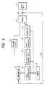
- Figs. 1A and 1B show whole block diagrams of a multi-value image encoding and decoding apparatus according to the first embodiment of the invention.
- the encoding apparatus will be first described.
- reference numeral 1 denotes a line buffer for holding an original image of an amount corresponding to three lines as an image width; 2 a predictor; and 3 a line buffer of three lines similar to the line buffer 1.
- the line buffer 3 stores data of a prediction result formed by the predictor 2.
- Reference numeral 4 denotes a prediction determination unit for determining a prediction method for an encode objective pixel with reference to the prediction result stored in the line buffer 3.
- Reference numeral 5 denotes a predictor similar to the predictor 2. The predictor 5 differs from the predictor 2 with respect to a point that the predictor 2 tries all of the prediction methods but the predictor 5 executes only the prediction instructed by the prediction determination unit 4.
- Reference numeral 6 denotes a differential unit for obtaining a difference between the encode objective pixel and the prediction value.
- Reference numeral 7 denotes an encoder for allocating a code to a differential value and outputting.
- a path from 101 to 103 via 102 is a system for merely perform only the prediction and it is sufficient that a predicting process until the pixel that is one-pixel preceding to the encode objective pixel has been finished at the time of the encoding and the process can be also executed at a speed higher than that.
- the image data of an amount corresponding to three lines of the image data that is inputted through the path 101 is stored into the line buffer 1.
- the bottom line among the three lines is the encoding line and the two upper lines are used for reference.
- Fig. 4 shows reference pixels in the lines for reference which are used in the embodiment.
- the predictor 2 executes six kinds of predictions (correlation measurement of the pixel values), which will be explained hereinlater, by using the peripheral pixels of each reference pixel. For each prediction, the predictor 2 generates "1" when the prediction error is smaller than a predetermined value and generates "0" when the prediction error is larger than the predetermined value. The resultant value is written into the line buffer 3. Thus, the prediction result of six bits is generated for one pixel.
- the prediction results at the positions corresponding to six peripheral pixels (encoded pixels which were subjected to the above predicting process) of the encode objective pixel are sent from the line buffer 3 to the prediction determination unit 4.
- the prediction determination unit 4 uses the prediction results of the peripheral pixels in the determination of a prediction method, which will be explained hereinlater, thereby determining which one of the six kinds of prediction methods is used.
- the prediction determination unit 4 outputs information indicative of the determined prediction method to the predictor 5.
- the predictor 5 On the basis of the information inputted from the prediction determination unit 4, the predictor 5 generates one prediction value by referring to the peripheral pixels of the encode objective pixel in the line buffer 1 through a data line 106 and outputs the prediction value to the differential unit 6 through a data line 107.
- the differential unit 6 forms a differential value by subtracting the prediction value inputted through the data line 107 from the encode objective pixel value inputted through a data line 108 and outputs the differential value to the encoder 7 through a data line 109.
- the encoder 7 Huffman encodes the differential value and outputs the encoded value via a data line 110. The whole operation has been described above.
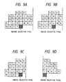
- the pixel values of the objective pixel in the line buffer 1 and the six peripheral pixels (A to F) of the objective pixel are used.
- the absolute value of the difference between the objective pixel and each of the six peripheral pixels is equal to or less than 5 (it is assumed that a dynamic range of the pixel lies within a range from 0 to 255), it is judged to be "effective", so that the prediction result value is set to 1.
- the absolute value is larger than 5, it is judged to be "ineffective", so that the prediction result value is set to 0.
- the prediction result value of six bits is generated for each objective pixel.
- the 6-bit data is written into a memory location in the line memory 3 corresponding to the objective pixel position.
- the prediction results of the six peripheral pixels at the positions corresponding to the encode pixels in the line buffer 3 are used.
- the prediction results are referred to as R 0 to R 5 .
- Each of the prediction results R 0 to R 5 is the data of six bits shown in Fig. 2 and generated at the time of the predicting process of the predictor 2.
- S(j) is defined as follows.
- the direction weight parameter P is used to raise a detecting precision of a pixel correlation by paying importance to R i corresponding to a certain pixel when a pixel correlation between the encode objective pixel and the certain pixel is detected by using R i of the six peripheral pixels.
- j which gives the maximum value of S(j) is set to an index of the prediction method.
- the prediction determination unit 4 outputs this value to the predictor 5.
- the above equation is an equation to measure the overall correlation among the pixel values with respect to regions #0 to #5 in Fig. 4.
- the correlation among the pixel values of the pixels around the encode objective pixel can be measured.
- Fig. 4 shows a state of the encode objective pixel and its peripheral pixels in the line buffer 1.
- reference numeral 8 denotes a decoder and 9 indicates an adder.
- a system of component elements 10 to 14 has a construction similar to the system of the component elements 1 to 5 in Fig. 1A.
- the encoded data outputted from the encoder 7 in Fig. 1A is inputted to the decoder 8 via a data line 111 and is decoded.
- the decoded differential value data is added by the adder 9 to a prediction value outputted from a predictor 14, which will be explained hereinlater.
- the addition value is outputted as reproduction data through a data line 113.
- the reproduced decoded data is stored into a line buffer 10.
- a prediction value of a decode objective pixel is outputted from the predictor 14 in a manner similar to the encoding apparatus side.
- the prediction value and the foregoing differential value data are added by the adder 9.
- the reference pixel regions #0 to #5 which are used for the prediction upon encoding in the above embodiment are not limited to the peripheral pixels of the encode objective pixel but can be also applied to a case such that the pixels of another picture plane is used as reference pixels.
- an encoding method of the encode objective pixel can be also predicted by using the pixels in a picture plane which is displayed at different times in a moving picture.
- the encoding method any one of a binary encoding and a multi-value encoding can be used. For example, it can be also applied to a binary encoding of a JBIG system.
- the prediction method of each pixel can be adaptively switched. Moreover, when deciding the prediction method, since the peripheral pixels which were encoded are used without using the encode objective pixel, the additional information indicative of the prediction method is unnecessary. Thus, an efficient encoding can be performed.
- the evaluating method used in the prediction determination unit 4 is very effective for prediction of an edge or a diagram and further raises an encoding efficiency of the encoding method of the embodiment.
- a pixel value prediction along a contour line on a luminance curved surface is most efficient for both of a smooth curved surface in an image and an edge or a thin line
- a contour line including the encode objective pixel is found out, and a prediction encoding is performed along the contour line.
- a direction having the largest luminance inclination is first searched from the encode objective pixel.
- the direction of the contour line can be specified.
- the second embodiment is characterized by obtaining the prediction value in the contour line direction obtained as mentioned above and an average value of a plurality of pixels in the contour line direction is used as a prediction value of the encode objective pixel. Therefore, a distribution of the noises decreases, an entropy of a prediction error decreases, and an encoding efficiency can be improved.
- the embodiment will now be described in detail hereinbelow.
- Fig. 5 shows a whole block diagram of a reversible encoding apparatus of a multi-value image according to an embodiment of the invention.
- reference numeral 21 denotes a line buffer for storing one line including the encode objective pixel and four lines preceding to such a line.
- the line buffer 21 is used when referring to the peripheral pixels of the encode objective pixel.
- Reference numeral 22 denotes a pixel interpolator. On the assumption that there is a pixel between the encode objective pixel and the peripheral pixels of the encode pixel, the pixel interpolator 22 obtains a value of such a pixel.
- the value of the pixel interpolated here and the values of the peripheral pixels of the encode objective pixel are stored into a memory 23.
- Reference numeral 24 denotes a maximum inclination judgment unit.
- the unit 24 can select the maximum luminance inclination for the directions (12 directions in the embodiment) which are radially directed to the outside from the encode objective pixel.
- Reference numeral 25 denotes an index converter. For an index indicative of the maximum inclination direction judged by the maximum inclination judgment unit 24, the index converter 25 generates an index of the direction which perpendicularly crosses the maximum inclination direction.
- Reference numeral 26 denotes a predictor for generating a prediction value by using the pixel in the contour line direction including the encode pixel or by using the interpolated pixel.
- Reference numeral 27 denotes a differential unit for generating a differential value obtained by subtracting the prediction value from the encode objective pixel value.
- Reference numeral 28 denotes a Huffman encoder for giving a Huffman code to the differential value.
- the pixel data inputted from a data line 201 is stored into the line buffer 21.
- the line buffer 21 it is assumed that a scanning line to be encoded and four preceding scanning lines which were encoded have been stored.
- the pixel interpolator 22 reads out the values of the peripheral pixels of R 0 to E 11 and A to T shown in Fig. 7 from the line buffer 21.
- the values of 0 to 3 or 0 to 2 are obtained by the following equations. Namely, the respective values are obtained by the following equations.
- the pixel interpolator 22 performs a process such as interpolation or the like in accordance with the above equations.
- the above 42 pixel values are stored into the memory 23 through a bus 202.
- the maximum inclination judgment unit 24 calculates an inclination by a method, which will be explained hereinlater, with reference to the 42 interpolation pixel values (reference pixel values) stored in the memory 23.
- the index in the maximum inclination direction is converted into the index in the contour line direction and the encoding prediction method is determined.
- the predictor 26 reads out the interpolation pixel values of the pixels existing in the index direction from the memory 23, calculates an average value of the pixel values of the number Nindex (index denotes the index in the contour line direction) as a prediction value, and outputs to the differential unit 27.
- the differential unit 27 subtracts the prediction value of the encode objective pixel from the value of the encode objective pixel stored in the line buffer 21 and outputs a differential value to the Huffman encoder 28.
- the Huffman encoder 28 performs a Huffman encoding to the differential value inputted from the differential unit 27 and outputs the encoded data to the decoding side through a data line 212.
- Fig. 6 shows an example of a block diagram of the decoding side.
- the encoded data outputted from the Huffman encoder 28 is decoded by a Huffman decoder 29 and is outputted as differential value data to an adder 30.
- Processes similar to those on the encoding side are executed with respect to a system from a line buffer 31-to a predictor 36.
- One line of the decode objective pixel and the decoded pixels of four lines preceding to such a line are stored into the line buffer 31.
- the same value as the output value of the predictor 26 is finally outputted from the predictor 36 to the adder 30 as a prediction value of the decode objective pixel.
- the adder 30 adds the differential value data that is inputted from the Huffman decoder to the prediction value which is inputted from the predictor 36 and reproduces and outputs the addition result as a pixel value of the decode objective pixel.
- the pixel value which was reproduced and outputted is inputted to an output unit 37 through a data line 215 and is also stored through a data line 216 into the line buffer 31 as a decoded pixel value.
- the determination of the encoding prediction method in the encoding method used in the above embodiment is performed by using the encoded peripheral pixels without using the encode objective pixel. Therefore, it can be commonly recognized on both of the encoding side and the decoding side, so that no additional information is needed.
- the maximum inclination direction has been detected and the prediction value has been determined by using the pixels in the direction that perpendicularly crosses the maximum inclination direction
- another method whereby the representative direction among a plurality of directions having inclinations which are equal to or larger than a predetermined inclination is detected in place of the maximum inclination direction or the like can be also properly selected.
- the invention is not limited to such an example but the encoding can be also performed by a software. With this method, the costs of the apparatus can be reduced.
- the prediction value is generated by a plurality of pixel values corresponding to the pixels existing in the contour line direction (irrespective of the method of judging the contour line direction, the prediction of the encode pixel can be precisely performed). Such an advantage is an effect of the embodiment which is obtained even in case of directly finding the contour line without indirectly searching the contour line.
Abstract
Description
- The invention relates to image processing apparatus and method for encoding and decoding image data.
- Hitherto, a DPCM (Differential Pulse Code Modulation) has widely been known as a reversible encoding system of a multi-value image. According to a general encoding by the DPCM, a prediction value (plane prediction) of an encode objective pixel is calculated by using encoded pixels existing around the encode objective pixel, namely, a left pixel (referred to as "a"), an upper pixel (likewise, "b"), and a left oblique pixel (likewise, "c") on the basis of, for example, an equation (a + b - c), and a difference between the prediction value and an encode objective pixel value is encoded.
- Generally, since many portions of the image are formed by a monotonous luminance inclination, almost of the portion of the encode objective pixel is accurately predicted by a prediction of the foregoing encode objective pixel and is encoded.
- However, in a high frequency portion in the pixel, namely, in an edge portion or a thin line portion, a large prediction error obviously occurs. In such a portion, a one-dimensional prediction in the direction of an edge or the extending direction is suitable instead of the plane prediction.
- As mentioned above, the optimum prediction method differs depending on a nature in the pixel. Although the optimum predicting direction differs every pixel, in the case where the user actually tries to perform the encoding, since additional information indicating which prediction method was used is added, an encoding efficiency deteriorates.
- As mentioned above, hitherto, there is a problem such that a prediction method of commonly efficiently encoding for both of a portion in which a pixel value has a gentle inclination and an edge portion or a thin line portion doesn't exist.
- There is also a problem such that when performing a prediction encoding by selectively using a plurality of prediction methods, the additional information to indicate which prediction method was selected is necessary and the encoding efficiency is low.
- To solve the above problems, therefore, it is a concern of the invention to perform an efficient encoding independent of a nature of an image.
- Another concern of the invention is to provide image processing apparatus and method which don't need additional information indicative of a prediction method of a pixel value.
- According to a preferred embodiment of the invention, there is provided an image processing apparatus comprising: forming means for measuring characteristics of first and second images for a plurality of pixels other than an encode objective pixel, thereby forming first and second measurement results, respectively; and encoding means for deciding an encoding method of the encode objective pixel on the basis of a plurality of first measurement results and a plurality of second measurement results and for encoding by using the decided encoding method.
- The above and other features of the present invention will become apparent from the following detailed description and the appended claims with reference to the accompanying drawings.
-
- Figs. 1A and 1B are diagrams showing an image encoding apparatus and a decoding apparatus according to the first embodiment;
- Fig. 2 is a diagram which is used for explaining a
predictor 2 in Fig. 1A; - Fig. 3 is a diagram which is used for explaining a
prediction determination unit 4 in Fig. 1A; - Fig. 4 is a diagram which is used for explaining a
predictor 5 in Fig. 1A; - Fig. 5 is a whole block diagram of an image encoding apparatus of the second embodiment;
- Fig. 6 is a whole block diagram of an image decoding apparatus of the second embodiment;
- Fig. 7 is a diagram for explaining peripheral pixels which are referred to in an image prediction of the second embodiment;
- Fig. 8 is a diagram for explaining the operation of a
pixel interpolator 22 in Fig. 5; and - Figs. 9A to 9D are diagrams for explaining the case where there are peripheral pixels which cannot be referred to.
- Figs. 1A and 1B show whole block diagrams of a multi-value image encoding and decoding apparatus according to the first embodiment of the invention.
- The encoding apparatus will be first described.
- In Fig. 1A,
reference numeral 1 denotes a line buffer for holding an original image of an amount corresponding to three lines as an image width; 2 a predictor; and 3 a line buffer of three lines similar to theline buffer 1. Theline buffer 3 stores data of a prediction result formed by thepredictor 2.Reference numeral 4 denotes a prediction determination unit for determining a prediction method for an encode objective pixel with reference to the prediction result stored in theline buffer 3.Reference numeral 5 denotes a predictor similar to thepredictor 2. Thepredictor 5 differs from thepredictor 2 with respect to a point that thepredictor 2 tries all of the prediction methods but thepredictor 5 executes only the prediction instructed by theprediction determination unit 4. -
Reference numeral 6 denotes a differential unit for obtaining a difference between the encode objective pixel and the prediction value.Reference numeral 7 denotes an encoder for allocating a code to a differential value and outputting. - The whole operation on the encoding side will now be described with reference to Fig. 1A.
- A path from 101 to 103 via 102 is a system for merely perform only the prediction and it is sufficient that a predicting process until the pixel that is one-pixel preceding to the encode objective pixel has been finished at the time of the encoding and the process can be also executed at a speed higher than that.
- First, the image data of an amount corresponding to three lines of the image data that is inputted through the
path 101 is stored into theline buffer 1. The bottom line among the three lines is the encoding line and the two upper lines are used for reference. Fig. 4 shows reference pixels in the lines for reference which are used in the embodiment. - With respect to each reference pixel which is referred to when the encode objective pixel is encoded, the
predictor 2 executes six kinds of predictions (correlation measurement of the pixel values), which will be explained hereinlater, by using the peripheral pixels of each reference pixel. For each prediction, thepredictor 2 generates "1" when the prediction error is smaller than a predetermined value and generates "0" when the prediction error is larger than the predetermined value. The resultant value is written into theline buffer 3. Thus, the prediction result of six bits is generated for one pixel. - When determining the prediction method of the encode objective pixel value upon encoding, the prediction results at the positions corresponding to six peripheral pixels (encoded pixels which were subjected to the above predicting process) of the encode objective pixel are sent from the
line buffer 3 to theprediction determination unit 4. - The
prediction determination unit 4 uses the prediction results of the peripheral pixels in the determination of a prediction method, which will be explained hereinlater, thereby determining which one of the six kinds of prediction methods is used. Theprediction determination unit 4 outputs information indicative of the determined prediction method to thepredictor 5. - On the basis of the information inputted from the
prediction determination unit 4, thepredictor 5 generates one prediction value by referring to the peripheral pixels of the encode objective pixel in theline buffer 1 through adata line 106 and outputs the prediction value to thedifferential unit 6 through adata line 107. - The
differential unit 6 forms a differential value by subtracting the prediction value inputted through thedata line 107 from the encode objective pixel value inputted through adata line 108 and outputs the differential value to theencoder 7 through adata line 109. - The
encoder 7 Huffman encodes the differential value and outputs the encoded value via adata line 110. The whole operation has been described above. - The prediction method in the
predictor 2 will now be described in detail with reference to Fig. 2. - As shown in Fig. 2, the pixel values of the objective pixel in the
line buffer 1 and the six peripheral pixels (A to F) of the objective pixel are used. In this instance, when the absolute value of the difference between the objective pixel and each of the six peripheral pixels is equal to or less than 5 (it is assumed that a dynamic range of the pixel lies within a range from 0 to 255), it is judged to be "effective", so that the prediction result value is set to 1. When the absolute value is larger than 5, it is judged to be "ineffective", so that the prediction result value is set to 0. - Thus, the prediction result value of six bits is generated for each objective pixel. The 6-bit data is written into a memory location in the
line memory 3 corresponding to the objective pixel position. - A method of deciding a prediction method in the
prediction determination unit 4 will now be described in detail with reference to Fig. 3. - As shown in Fig. 3, the prediction results of the six peripheral pixels at the positions corresponding to the encode pixels in the line buffer 3 (corresponding to the positions of A to F when the encode objective pixel is set to the objective pixel) are used. The prediction results are referred to as R0 to R5.
- Each of the prediction results R0 to R5 is the data of six bits shown in Fig. 2 and generated at the time of the predicting process of the
predictor 2. - It is now assumed that the prediction result value of one bit indicating effective/ineffective corresponding to the j-th prediction method of Ri (i = 0 to 5) corresponding to the six peripheral pixels of the encode objective pixel is set to Ri(j), an evaluation value for the j-th prediction method in the region of R0 to R5 is set to S(j). S(j) is defined as follows.

prediction determination unit 4 outputs this value to thepredictor 5. - That is, the above equation is an equation to measure the overall correlation among the pixel values with respect to
regions # 0 to #5 in Fig. 4. The correlation among the pixel values of the pixels around the encode objective pixel can be measured. - The operation of the
predictor 5 will now be described in detail with reference to Fig. 4. Fig. 4 shows a state of the encode objective pixel and its peripheral pixels in theline buffer 1. - The
predictor 5 outputs a prediction value in accordance with the index inputted from theprediction determination unit 4. For example, when the index j = O is inputted, the value of #0 as a prediction value by the zeroth prediction method is outputted. This value is supplied to thedifferential unit 6. - The decoding apparatus will now be described with reference to Fig. 1B.
- In Fig. 1B, reference numeral 8 denotes a decoder and 9 indicates an adder. A system of
component elements 10 to 14 has a construction similar to the system of thecomponent elements 1 to 5 in Fig. 1A. - The encoded data outputted from the
encoder 7 in Fig. 1A is inputted to the decoder 8 via a data line 111 and is decoded. The decoded differential value data is added by the adder 9 to a prediction value outputted from apredictor 14, which will be explained hereinlater. The addition value is outputted as reproduction data through adata line 113. - The reproduced decoded data is stored into a
line buffer 10. - In a circuit from a
predictor 11 to thepredictor 14, the operations similar to those on the encoding apparatus side are executed. A prediction value of a decode objective pixel is outputted from thepredictor 14 in a manner similar to the encoding apparatus side. The prediction value and the foregoing differential value data are added by the adder 9. - The reference
pixel regions # 0 to #5 which are used for the prediction upon encoding in the above embodiment are not limited to the peripheral pixels of the encode objective pixel but can be also applied to a case such that the pixels of another picture plane is used as reference pixels. For example, an encoding method of the encode objective pixel can be also predicted by using the pixels in a picture plane which is displayed at different times in a moving picture. As for the encoding method, any one of a binary encoding and a multi-value encoding can be used. For example, it can be also applied to a binary encoding of a JBIG system. - According to the embodiment as mentioned above, the prediction method of each pixel can be adaptively switched. Moreover, when deciding the prediction method, since the peripheral pixels which were encoded are used without using the encode objective pixel, the additional information indicative of the prediction method is unnecessary. Thus, an efficient encoding can be performed.
- The evaluating method used in the
prediction determination unit 4 is very effective for prediction of an edge or a diagram and further raises an encoding efficiency of the encoding method of the embodiment. - According to the second embodiment, attention is newly paid to a fact that a pixel value prediction along a contour line on a luminance curved surface is most efficient for both of a smooth curved surface in an image and an edge or a thin line, a contour line including the encode objective pixel is found out, and a prediction encoding is performed along the contour line.
- To accomplish the above prediction encoding, a direction having the largest luminance inclination is first searched from the encode objective pixel.
- Since the contour line perpendicularly crosses the steepest luminance inclination, by searching such a contour line, the direction of the contour line can be specified.
- The reason why the contour line direction is not directly searched will now be described hereinbelow. In the direction near the contour line, all of the luminance inclinations are small and the direction of the true contour line is hidden by noise components on the image. On the other hand, according to the method of obtaining the steepest inclination, since a power of a low frequency having a large inclination is larger than a power of noises, there is an advantage such that the steepest inclination direction can be relatively easily or precisely known.
- The second embodiment is characterized by obtaining the prediction value in the contour line direction obtained as mentioned above and an average value of a plurality of pixels in the contour line direction is used as a prediction value of the encode objective pixel. Therefore, a distribution of the noises decreases, an entropy of a prediction error decreases, and an encoding efficiency can be improved. The embodiment will now be described in detail hereinbelow.
- Fig. 5 shows a whole block diagram of a reversible encoding apparatus of a multi-value image according to an embodiment of the invention.
- In Fig. 5,
reference numeral 21 denotes a line buffer for storing one line including the encode objective pixel and four lines preceding to such a line. Theline buffer 21 is used when referring to the peripheral pixels of the encode objective pixel. -
Reference numeral 22 denotes a pixel interpolator. On the assumption that there is a pixel between the encode objective pixel and the peripheral pixels of the encode pixel, thepixel interpolator 22 obtains a value of such a pixel. - The value of the pixel interpolated here and the values of the peripheral pixels of the encode objective pixel are stored into a
memory 23. -
Reference numeral 24 denotes a maximum inclination judgment unit. Theunit 24 can select the maximum luminance inclination for the directions (12 directions in the embodiment) which are radially directed to the outside from the encode objective pixel. -
Reference numeral 25 denotes an index converter. For an index indicative of the maximum inclination direction judged by the maximuminclination judgment unit 24, theindex converter 25 generates an index of the direction which perpendicularly crosses the maximum inclination direction. -
Reference numeral 26 denotes a predictor for generating a prediction value by using the pixel in the contour line direction including the encode pixel or by using the interpolated pixel. -
Reference numeral 27 denotes a differential unit for generating a differential value obtained by subtracting the prediction value from the encode objective pixel value.Reference numeral 28 denotes a Huffman encoder for giving a Huffman code to the differential value. - The whole operation will now be described with reference to Fig. 5.
- The pixel data inputted from a
data line 201 is stored into theline buffer 21. In the embodiment, it is assumed that a scanning line to be encoded and four preceding scanning lines which were encoded have been stored. - The
pixel interpolator 22 reads out the values of the peripheral pixels of R0 to E11 and A to T shown in Fig. 7 from theline buffer 21. By using those pixel values, as for the 42 pixels r0(j) to r11(j)/(j) corresponding to 12 directions shown in Fig. 8, the values of 0 to 3 or 0 to 2 are obtained by the following equations. Namely, the respective values are obtained by the following equations.


- In case of the encode objective pixel position in Figs. 9A to 9D such that a part of the edge points cannot be referred to, only the directions of Ri which can be referred to are used as targets of the directions which are used at a maximum inclination judgment, which will be explained hereinlater, and nothing is considered with respect to the other directions.
- The
pixel interpolator 22 performs a process such as interpolation or the like in accordance with the above equations. The above 42 pixel values are stored into thememory 23 through abus 202. - The maximum
inclination judgment unit 24 calculates an inclination by a method, which will be explained hereinlater,
memory 23. - Now, assuming that the direction of Ri is set to "direction i", the value of the inclination in the i direction is set to Gi. The number of interpolation pixels in the i direction assumes Ni and Gi is defined by the following equation.

- The maximum
inclination judgment unit 24 obtains Gi with respect to i (= O to 11) and outputs a value which gives maximum Gi to theindex converter 25. - Now, assuming that an input to the
index converter 25 is set to Din and an output from the index converter is set to Dout,
- Thus, the index in the maximum inclination direction is converted into the index in the contour line direction and the encoding prediction method is determined.
- In accordance with the index direction which is outputted from the
index converter 25, thepredictor 26 reads out the interpolation pixel values of the pixels existing in the index direction from thememory 23, calculates an average value of the pixel values of the number Nindex (index denotes the index in the contour line direction) as a prediction value, and outputs to thedifferential unit 27. - The
differential unit 27 subtracts the prediction value of the encode objective pixel from the value of the encode objective pixel stored in theline buffer 21 and outputs a differential value to theHuffman encoder 28. - The
Huffman encoder 28 performs a Huffman encoding to the differential value inputted from thedifferential unit 27 and outputs the encoded data to the decoding side through adata line 212. - Fig. 6 shows an example of a block diagram of the decoding side. The encoded data outputted from the
Huffman encoder 28 is decoded by aHuffman decoder 29 and is outputted as differential value data to anadder 30. Processes similar to those on the encoding side are executed with respect to a system from a line buffer 31-to apredictor 36. One line of the decode objective pixel and the decoded pixels of four lines preceding to such a line are stored into theline buffer 31. The same value as the output value of thepredictor 26 is finally outputted from thepredictor 36 to theadder 30 as a prediction value of the decode objective pixel. - The
adder 30 adds the differential value data that is inputted from the Huffman decoder to the prediction value which is inputted from thepredictor 36 and reproduces and outputs the addition result as a pixel value of the decode objective pixel. The pixel value which was reproduced and outputted is inputted to anoutput unit 37 through adata line 215 and is also stored through adata line 216 into theline buffer 31 as a decoded pixel value. - The determination of the encoding prediction method in the encoding method used in the above embodiment is performed by using the encoded peripheral pixels without using the encode objective pixel. Therefore, it can be commonly recognized on both of the encoding side and the decoding side, so that no additional information is needed.
- As a Huffman encoding of the differential value according to the embodiment, another encoding method such as arithmetic encoding, Golowb-Rioe encoding, or the like can be substituted.
- With respect to the position (the first pixel of the line) in Fig. 9D, it is also possible to control in a manner such that an actual pixel value is encoded and sent instead of the differential value and is decoded as an actual pixel value on the decoding side.
- With respect to the first four lines of the image, it is also possible to control in a manner such that by setting the index that is determined by the
predictor 26, the differential value between such an index and a preset direction is sent. - Further, in the above embodiment, although the maximum inclination direction has been detected and the prediction value has been determined by using the pixels in the direction that perpendicularly crosses the maximum inclination direction, another method whereby the representative direction among a plurality of directions having inclinations which are equal to or larger than a predetermined inclination is detected in place of the maximum inclination direction or the like can be also properly selected.
- According to the first and second embodiments as mentioned above, it is possible to provide the encoding method whereby an efficient encoding which doesn't depend on the nature of the image can be performed and, further, the additional information indicative of the prediction method of the pixel value is unnecessary.
- In the embodiment, although the encoding has been performed by the hardware, the invention is not limited to such an example but the encoding can be also performed by a software. With this method, the costs of the apparatus can be reduced. In the embodiment, since the prediction value is generated by a plurality of pixel values corresponding to the pixels existing in the contour line direction (irrespective of the method of judging the contour line direction, the prediction of the encode pixel can be precisely performed). Such an advantage is an effect of the embodiment which is obtained even in case of directly finding the contour line without indirectly searching the contour line.
- The present invention is not limited to the foregoing embodiments but many modifications and variations are possible within the spirit and scope of the appended claims of the invention.
Claims (22)
- An image processing apparatus comprising:forming means for measuring a feature of a first image and a feature of a second image for a plurality of pixels other than an encode objective pixel, thereby forming a first measurement result and a second measurement result, respectively; andencoding means for determining an encoding method of said encode objective pixel on the basis of a plurality of said first measurement results and a plurality of said second measurement results and for encoding by using said encoding method.
- An apparatus according to claim 1, wherein the pixels other than said encode objective pixel are pixels which were encoded before said encode objective pixel.
- An apparatus according to claim 1, wherein the feature of said first image and the feature of said second image are correlations among pixel values between the pixels other than said encode objective pixel and one of peripheral pixels of the pixels of said encode objective pixel.
- An apparatus according to claim 1, wherein said correlations among the pixel values are obtained on the basis of differences among the pixel values of the pixels other than said encode objective pixel and the peripheral pixels of said pixels.
- An apparatus according to claim 1, wherein the encoding by said encoding means is a differential encoding.
- An apparatus according to claim 1, wherein in the encoding by said encoding means, the encoding method of said encode objective pixel is determined on the basis of not only said first and second measurement results but also a third measurement result measured in a manner similar to said first and second measurement results.
- An image processing method comprising:a forming step of measuring a feature of a first image and a feature of a second image for a plurality of pixels other than an encode objective pixel, thereby forming a first measurement result and a second measurement result, respectively; andan encoding step of determining an encoding method of said encode objective pixel on the basis of a plurality of said first measurement results and a plurality of said second measurement results and encoding by using said encoding method.
- An image processing apparatus comprising:forming means for measuring a feature of a first image and a feature of a second image for a plurality of pixels other than an encode objective pixel, thereby forming a first measurement result and a second measurement result, respectively; anddecoding means for judging a feature of an image for said encode objective pixel on the basis of a plurality of said first measurement results and a plurality of said second measurement results and for decoding in accordance with said judged feature of the image.
- An image processing method comprising:a forming step of measuring a feature of a first image and a feature of a second image for a plurality of pixels other than an encode objective pixel, thereby forming a first measurement result and a second measurement result, respectively; anda decoding step of judging a feature of an image for said encode objective pixel on the basis of a plurality of said first measurement results and a plurality of said second measurement results and decoding in accordance with said judged feature of the image.
- An image processing apparatus comprising:output means for outputting a first value indicative of a correlation with a pixel having a first positional relation for peripheral pixels of an encode objective pixel and a second value indicative of a correlation with a pixel having a second positional relation for said peripheral pixels; andencoding means for determining an encoding method of said encode objective pixel on the basis of a plurality of said first values and a plurality of said second values which were outputted by said output means and for encoding by using said encoding method.
- An image processing method comprising:an outputting step of outputting a first value indicative of a correlation with a pixel having a first positional relation for peripheral pixels of an encode objective pixel and a second value indicative of a correlation with a pixel having a second positional relation for said peripheral pixels; andan encoding step of determining an encoding method of said encode objective pixel on the basis of a plurality of said first values and a plurality of said second values which were outputted in said outputting step and encoding by using said encoding method.
- An image processing apparatus comprising:judging means for judging a first direction having a desired correlation with an encode objective pixel on the basis of pixels other than said encode objective pixel; andencoding means for determining a second direction in accordance with said first direction judged by said judging means and for encoding by using said encode objective pixel and a pixel existing in said second direction of said encode objective pixel.
- An apparatus according to claim 12, wherein there is a perpendicular relation between said first and second directions.
- An apparatus according to claim 12, wherein a case of using a virtual pixel value exists in a part of pixel values which are used when said judging means judges said first direction.
- An apparatus according to claim 12, wherein the encoding by said encoding means is an entropy encoding.
- An apparatus according to claim 12, wherein said desired correlation is a correlation between said encode objective pixel and a direction such that an inclination of the pixel value among a plurality of directions from the encode objective pixel is maximum.
- An image processing method comprising:a judging step of judging a first direction having a desired correlation with an encode objective pixel on the basis of pixels other than said encode objective pixel; andan encoding step of determining a second direction in accordance with said first direction judged in said judging step and encoding by using said encode objective pixel and a pixel existing in said second direction of said encode objective pixel.
- An image processing apparatus comprising:judging means for judging a first direction having a desired correlation with a decode objective pixel on the basis of pixels other than said decode objective pixel; anddecoding means for determining a second direction in accordance with said first direction judged by said judging means and for decoding by using said decode objective pixel and a pixel existing in said second direction of said decode objective pixel.
- An image processing method comprising:a judging step of judging a first direction having a desired correlation with a decode objective pixel on the basis of pixels other than said decode objective pixel; anda decoding step of determining a second direction in accordance with said first direction judged in said judging step and decoding by using said decode objective pixel and a pixel existing in said second direction of said decode objective pixel.
- An image processing apparatus comprising:judging means for judging a contour line of a pixel value corresponding to an encode objective pixel on the basis of pixels other than said encode objective pixel; andencoding means for generating a prediction value by using a plurality of pixel values corresponding to the direction of the contour line of said pixel value and for differentially encoding said encode objective pixel by using said prediction value.
- An image processing method comprising:a judging step of judging a contour line of a pixel value corresponding to an encode objective pixel on the basis of pixels other than said encode objective pixel; andan encoding step of generating a prediction value by using a plurality of pixel values corresponding to the direction of the contour line of said pixel value and differentially encoding said encode objective pixel by using said prediction value.
- Encoding apparatus for encoding image pixels comprising first means for predicting the value of an object pixel using a plurality of prediction processes, and second means for predicting the value of the object pixel using a process determined by the outcome of said first means.
Applications Claiming Priority (4)
| Application Number | Priority Date | Filing Date | Title |
|---|---|---|---|
| JP11720195A JPH08317403A (en) | 1995-05-16 | 1995-05-16 | Device and method for image processing |
| JP11720295A JPH08317401A (en) | 1995-05-16 | 1995-05-16 | Device and method for image processing |
| JP117202/95 | 1995-05-16 | ||
| JP117201/95 | 1995-05-16 |
Publications (2)
| Publication Number | Publication Date |
|---|---|
| EP0743794A2 true EP0743794A2 (en) | 1996-11-20 |
| EP0743794A3 EP0743794A3 (en) | 1998-06-03 |
Family
ID=26455362
Family Applications (1)
| Application Number | Title | Priority Date | Filing Date |
|---|---|---|---|
| EP96303381A Withdrawn EP0743794A3 (en) | 1995-05-16 | 1996-05-14 | Image encoding apparatus and method |
Country Status (2)
| Country | Link |
|---|---|
| US (1) | US6014463A (en) |
| EP (1) | EP0743794A3 (en) |
Cited By (4)
| Publication number | Priority date | Publication date | Assignee | Title |
|---|---|---|---|---|
| WO1998026606A1 (en) * | 1996-12-12 | 1998-06-18 | Thomson Consumer Electronics, Inc. | Image element processor for a memory management system using recompression |
| WO2001084848A2 (en) * | 2000-05-02 | 2001-11-08 | Zaxel Systems, Inc. | Loss less image compression |
| US7415162B2 (en) | 2003-05-27 | 2008-08-19 | Zaxel Systems, Inc. | Method and apparatus for lossless data transformation with preprocessing by adaptive compression, multidimensional prediction, multi-symbol decoding enhancement enhancements |
| US7428341B2 (en) | 2003-05-27 | 2008-09-23 | Zaxel Systems, Inc. | Method and apparatus for lossless data transformation with preprocessing by adaptive compression, multidimensional prediction, multi-symbol decoding enhancement enhancements |
Families Citing this family (8)
| Publication number | Priority date | Publication date | Assignee | Title |
|---|---|---|---|---|
| JP3270008B2 (en) * | 1998-06-26 | 2002-04-02 | 沖電気工業株式会社 | Shape information encoding / decoding device |
| JP2002077920A (en) * | 2000-08-28 | 2002-03-15 | Sony Corp | Picture compressing apparatus and method therefor |
| GB2387056A (en) * | 2002-03-28 | 2003-10-01 | Sony Uk Ltd | Differential encoding and decoding |
| WO2004075556A1 (en) * | 2003-02-19 | 2004-09-02 | Ishikawajima-Harima Heavy Industries Co., Ltd. | Image compression device, image compression method, image compression program, compression/encoding method, compression/encoding device, compression/encoding program, decoding method, decoding device, and decoding program |
| US7418146B2 (en) * | 2004-02-10 | 2008-08-26 | Sanyo Electric Co., Ltd. | Image decoding apparatus |
| JP5082548B2 (en) * | 2007-03-30 | 2012-11-28 | 富士通株式会社 | Image processing method, encoder and decoder |
| ATE524927T1 (en) * | 2008-01-21 | 2011-09-15 | Ericsson Telefon Ab L M | IMAGE PROCESSING BASED ON PREDICTION |
| US9558535B2 (en) * | 2012-08-07 | 2017-01-31 | Sharp Kabushiki Kaisha | Image processing device, image processing method, image processing program, and image display device |
Family Cites Families (6)
| Publication number | Priority date | Publication date | Assignee | Title |
|---|---|---|---|---|
| GB2101838B (en) * | 1981-04-20 | 1986-03-05 | Canon Kk | Image processing method and apparatus therefor |
| IL77840A (en) * | 1986-02-10 | 1989-05-15 | Elscint Ltd | Data compression system for digital imaging |
| US4941045A (en) * | 1988-10-11 | 1990-07-10 | Scientific-Atlanta, Inc. | Method and apparatus for improving vertical definition of a television signal by scan conversion |
| US5086487A (en) * | 1988-11-24 | 1992-02-04 | Canon Kabushiki Kaisha | Method and apparatus for image encoding in which reference pixels for predictive encoding can be selected based on image size |
| EP0372950B1 (en) * | 1988-12-08 | 1995-07-05 | Canon Kabushiki Kaisha | Image reducing apparatus |
| FR2695497A1 (en) * | 1992-09-09 | 1994-03-11 | Philips Electronique Lab | Device for coding still images. |
-
1996
- 1996-05-14 US US08/645,590 patent/US6014463A/en not_active Expired - Lifetime
- 1996-05-14 EP EP96303381A patent/EP0743794A3/en not_active Withdrawn
Non-Patent Citations (7)
| Title |
|---|
| A. NETRAVALI, J.O. LIMB: "Picture Coding: A Review" PROCEEDINGS OF THE IEEE, vol. 68, no. 3, March 1980, pages 366-407, XP002039933 * |
| C. ZHANG: "Ein neuer adaptiver Pr{diktor f}r die DPCM-Codierung von Fernsehsignalen" FREQUENZ, vol. 36, no. 6, June 1982, BERLIN, pages 162-168, XP002039932 * |
| NOBUTAKA KUROKI ET AL: "LOSSLESS IMAGE COMPRESSION BY TWO-DIMENSIONAL LINEAR PREDICTION WITH VARIABLE COEFFICIENTS" IEICE TRANSACTIONS ON FUNDAMENTALS OF ELECTRONICS, COMMUNICATIONS AND COMPUTER SCIENCES, vol. E75 - A, no. 7, XP000311782 * |
| P. COHEN, J.P. ADOUL: "Adaptive Differential Coding of Picture Signals Based on Local Contour Prediction" NATIONAL TELECOMMUNICATIONS CONFERENCE, 1976, pages 6.1-1-6.1-5, XP002039931 * |
| PISCAGLIA P ET AL: "LOSSLESS HIERARCHICAL STORAGE OF IMAGES" EUROPEAN TRANSACTIONS ON TELECOMMUNICATIONS AND RELATED TECHNOLOGIES, vol. 6, no. 3, 1 May 1995, pages 267-274, XP000527580 * |
| ROBERT E. GRAHAM: "Predictive Quantizing of Television Signals" IRE WESCON CONVENTION RECORD, vol. 2, 19 - 22 August 1958, pages 147-157, XP002051791 * |
| W. ZSCHUNKE: "DPCM Picture Coding with Adaptive Prediction" IEEE TRANSACTIONS ON COMMUNICATIONS, vol. 25, no. 11, November 1977, pages 1295-1301, XP002039929 * |
Cited By (7)
| Publication number | Priority date | Publication date | Assignee | Title |
|---|---|---|---|---|
| WO1998026606A1 (en) * | 1996-12-12 | 1998-06-18 | Thomson Consumer Electronics, Inc. | Image element processor for a memory management system using recompression |
| US5844608A (en) * | 1996-12-12 | 1998-12-01 | Thomson Consumer Electronics, Inc. | Picture element processor for a memory management system |
| WO2001084848A2 (en) * | 2000-05-02 | 2001-11-08 | Zaxel Systems, Inc. | Loss less image compression |
| WO2001084848A3 (en) * | 2000-05-02 | 2002-02-07 | Zaxel Systems Inc | Loss less image compression |
| US7415162B2 (en) | 2003-05-27 | 2008-08-19 | Zaxel Systems, Inc. | Method and apparatus for lossless data transformation with preprocessing by adaptive compression, multidimensional prediction, multi-symbol decoding enhancement enhancements |
| US7428341B2 (en) | 2003-05-27 | 2008-09-23 | Zaxel Systems, Inc. | Method and apparatus for lossless data transformation with preprocessing by adaptive compression, multidimensional prediction, multi-symbol decoding enhancement enhancements |
| US7515762B2 (en) | 2003-05-27 | 2009-04-07 | Zaxel Systems, Inc. | Method and apparatus for lossless data transformation with preprocessing by adaptive compression, multidimensional prediction, multi-symbol decoding enhancement enhancements |
Also Published As
| Publication number | Publication date |
|---|---|
| EP0743794A3 (en) | 1998-06-03 |
| US6014463A (en) | 2000-01-11 |
Similar Documents
| Publication | Publication Date | Title |
|---|---|---|
| US7046850B2 (en) | Image matching | |
| US6078689A (en) | Image information encoding device | |
| US6792157B1 (en) | Image encoding apparatus and quantization characteristics determining apparatus | |
| US5917963A (en) | Image processing apparatus and image processing method | |
| EP0447068B1 (en) | Motion image data compression system | |
| EP0743794A2 (en) | Image encoding apparatus and method | |
| KR960040026A (en) | Resolution conversion device and resolution conversion method | |
| JPH02177766A (en) | Hierarchical encoding system for binary image | |
| US6021230A (en) | Interpolation method for binary image | |
| KR100239307B1 (en) | Contour image encoder | |
| EP0535684A1 (en) | A method for predictive video compression coding | |
| JP3432039B2 (en) | Image encoding method and apparatus | |
| JP4862186B2 (en) | Predictive processing system | |
| JPH08317403A (en) | Device and method for image processing | |
| JP2812232B2 (en) | Halftone image data compression method | |
| JPS63305672A (en) | Block encoding system for multi-valued image | |
| KR100243862B1 (en) | Method and apparatus for concealing errors in a transmitted video signal | |
| JPH08317401A (en) | Device and method for image processing | |
| JP2941843B2 (en) | Apparatus and method for reducing image signal | |
| US6009211A (en) | Hadamard transform coefficient predictor | |
| JP2000200349A (en) | Device and method for converting image information and device and method for learning | |
| JP3263218B2 (en) | Image information data compression and playback device | |
| JP2934156B2 (en) | Hierarchical motion detection method and apparatus | |
| JP2000134511A (en) | Device and method for converting image information | |
| JP3070535B2 (en) | Patent application title: Pattern matching encoding device, pattern matching encoding method, and medium recording control program for pattern matching encoding device |
Legal Events
| Date | Code | Title | Description |
|---|---|---|---|
| PUAI | Public reference made under article 153(3) epc to a published international application that has entered the european phase |
Free format text: ORIGINAL CODE: 0009012 |
|
| AK | Designated contracting states |
Kind code of ref document: A2 Designated state(s): DE FR GB |
|
| PUAL | Search report despatched |
Free format text: ORIGINAL CODE: 0009013 |
|
| AK | Designated contracting states |
Kind code of ref document: A3 Designated state(s): DE FR GB |
|
| 17P | Request for examination filed |
Effective date: 19981014 |
|
| 17Q | First examination report despatched |
Effective date: 19990902 |
|
| STAA | Information on the status of an ep patent application or granted ep patent |
Free format text: STATUS: THE APPLICATION IS DEEMED TO BE WITHDRAWN |
|
| 18D | Application deemed to be withdrawn |
Effective date: 20041201 |