EP0744873A2 - Method for coordinating data changes among central office switches - Google Patents
Method for coordinating data changes among central office switches Download PDFInfo
- Publication number
- EP0744873A2 EP0744873A2 EP96303404A EP96303404A EP0744873A2 EP 0744873 A2 EP0744873 A2 EP 0744873A2 EP 96303404 A EP96303404 A EP 96303404A EP 96303404 A EP96303404 A EP 96303404A EP 0744873 A2 EP0744873 A2 EP 0744873A2
- Authority
- EP
- European Patent Office
- Prior art keywords
- switch
- message
- data
- work order
- directing
- Prior art date
- Legal status (The legal status is an assumption and is not a legal conclusion. Google has not performed a legal analysis and makes no representation as to the accuracy of the status listed.)
- Granted
Links
Images


Classifications
-
- H—ELECTRICITY
- H04—ELECTRIC COMMUNICATION TECHNIQUE
- H04Q—SELECTING
- H04Q3/00—Selecting arrangements
- H04Q3/0016—Arrangements providing connection between exchanges
Definitions
- This invention relates to the field of telecommunications networks and, more particularly, to coordinating data changes among central office switches in such telecommunications networks.
- Transferring a customer line from one central office switch to another requires manually retrieving customer line data from a first switch and entering the same data into the memory of a second switch. If adding a new service feature is the impetus for the transfer, additional data specific to the newly added service feature must also be entered into the customer data file in the second switch. Since each central office switch typically serves one or more "blocks" of directory numbers (collectively having given office codes) wherein each block of directory numbers has a unique office code, the transfer of a customer line from one switch to another switch normally implies a directory number change.
- the prior art coordinated data exchange process is initiated by a central provisioning system which is maintained by a local exchange carrier (LEC) and serves all central office switches in a local telecommunications network.
- LEC local exchange carrier
- transferring customer line data from a first central office switch to a second central office switch requires the intervention of a service technician who receives a service work order from the central provisioning system, manually retrieves all data associated with a given customer directory number from a first central office switch and then manually installs the directory number data into a second central office switch.
- the current process for customer directory number data transfer among central office switches is exemplified by the following scenario: A customer who is currently served by an analog switch decides to set up a home office. She plans to install a facsimile machine and personal computer in her home office and determines it would be beneficial to have ISDN service on her telephone line. Accordingly, the customer contacts a service representative of her local exchange carrier and requests ISDN service. Although the customer wants ISDN service, she clearly specifies that she does not want to change her current directory number of "708-555-1234". In response to the customer's request, the service representative enters a service order to provide ISDN service to the customer line identified by the directory number "708-555-1234" into a customer service operation support system (OSS).
- OSS customer service operation support system
- the service order reaches the central provisioning system which evaluates the order and if possible (i.e. if the LEC maintains a switch capable of providing ISDN to this customer), issues a work order ticket indicating that ISDN service is to be provided to the customer line identified by the directory number "708-555-1234".
- the central office switch which serves directory number "708-555-1234" is an analog switch which is incapable of providing ISDN service.
- the LEC also maintains a digital switch (such as the 5ESS® switch sold by AT&T Network Systems) which is capable of providing ISDN service.
- the customer's line must be wired to the digital switch. Nevertheless, in accordance with the customer's request, her local directory number of "708-555-1234" and all existing features of her telephone service must not change.
- a LEC technician physically wires a new customer line from a main distributing frame to the digital central office switch, he retrieves all customer data relating to directory number "708-555-1234" stored in the analog central office switch and enters the retrieved data and the newly requested ISDN feature into the digital central office switch.
- the technician must also program a new routing index in a separate database so that incoming calls may be properly delivered to the directory number, as is known in the art.
- the technician severs the connection to the analog switch. Due to the manual retrieval and installation of data, the process is labor-intensive, time-consuming and prone to error. Therefore, there is a need in the art for automatically retrieving and installing customer data in a central office switch in response to a work order message received from a provisioning system in a local telecommunications network.
- the message directing switch is a digital switching system which includes the capability to process all work order messages issued by a central provisioning system which is maintained by a local exchange carrier. More particularly, the digital switch (which may be the "new" switch in a capping scenario) serves as a receiving point for work order messages issued by the central provisioning system. Work order messages determined by the message directing switch to be in a foreign format are delivered to another switch (i.e. the message receiving switch which may be the "old" switch in a capping scenario) for processing therein. Work order messages which require coordinated data exchanges between switches are processed under the control of the message directing switch which uses a transfer processor to carry out a data transfer protocol.
- the message directing switch formulates a data query in order to retrieve specific data from the switch acting as the message receiving switch. Once the data is received in the message directing switch, it used for normal provisioning processes. Eventually, the message directing switch directs the message receiving switch to delete the data it previously sent to the message directing switch, so that duplicate data is not maintained.
- FIGs. 1A and 1B show local telecommunications network 100 including first digital central office switch 110 which has message directing capabilities and is designated the "message directing switch".
- Two other switches namely, analog central office switch 140 and digital central office switch 170 are standard central office switches which do not possess message directing capabilities and are generally referred to as "message receiving switches".
- message directing switch 110 is the "new" switch and analog switch 140 is the "old” switch.
- Digital switch 170 is included to emphasize that any switch (analog or digital) may be a message receiving switch and that message directing switch 110 may coordinate data transfers in which digital switch 170 is the "new" switch in a capping scenario, as explained in detail below.
- an operational telecommunications network may include many more switches and that message directing switch 110 may interact with a cluster of central office switches which act as message receiving switches.
- point code converter 104 which routes incoming telephone calls from public-switched telephone network (PSTN) 102 to a central office switch in local telecommunications network 100 for those customer lines which retain directory numbers during switch change-overs.
- PSTN public-switched telephone network
- a detailed description of the operation of point code converter 104 can be found in commonly assigned U.S. patent 5,048,081 to Gavaras et al. entitled "Arrangement for Routing Packetized Messages" which issued on September 10, 1991 (hereinafter, the Gavaras et al. patent).
- Provisioning system 150 communicates with message directing switch 110 via data link 162 and in one preferred embodiment may communicate with analog switch 140 and second digital switch 170 via data link 164 and data link 174, respectively.
- Message directing switch 110 and analog switch 140 communicate with each other over intra-switch data link 166 while message directing switch 110 and second digital switch 170 communicate with each other over intra-switch data link 176.
- message directing switch 110 is a digital switch with message directing capabilities such as the 5ESS® switch manufactured and sold by AT&T Network Systems.
- Switch 110 includes three major components: an administrative module (AM) 114 which provides system wide administration, maintenance, and resource allocation; a communications module (CM) 116 which is a hub for distributing and switching voice or digital data, control information, and synchronization signals; and a plurality of switching modules (SMs) 118 and 120 which perform local switching and control functions as well as provide interfaces to customer lines A, B, C and D'.
- Remote switching module RSM 122 is similar to switching modules 118 and 120 but it serves distant customer lines E and F via a digital loop carrier (DLC) (not shown).
- DLC digital loop carrier
- Host switching module HSM 124 is the only switching module in direct communication with PSTN 102. All communication among the elements of message directing switch 110 (including communication among all SMs and between AM 114 and CM 116) is accomplished over Network Control and Time (NCT) links 125. Also shown is interface 132 which receives ported directory number routing information over message link 105 from point code converter 104 in accordance with the teaching of the Gavaras et al. patent.
- NCT Network Control and Time
- AM 114 provides system level interfaces required to operate, administer, and maintain message director switch 110.
- AM 114 comprises main processor 111, memory 113 and transfer processor 115.
- Transfer processor 115 is the interface to provisioning system 150 and controls all coordinated data provisioning functions among message directing switch 110, and analog switch 140 and digital switch 170 which act in a message receiving capacity, as described in detail below.
- Each switching module in message directing switch 110 includes a controller 127 which coordinates global functions, memory 128 for retaining specific customer line data and network element 129 for routing calls to and from individual customer lines. Consistent with connections in digital switch art, all SMs are connected by two NCT links to CM 116.
- Analog switch 140 is representative of an "old" switch in a capping scenario and includes processor 142 for global functions such as common resource allocation and maintenance control, memory 144 for storing various control programs and two switching modules SM 146 and SM 148 which serve customer lines A' B' and C' D', respectively.
- Customer line D' is connected to both SM 148 of analog switch 140 and SM 120 of message directing switch 110.
- the dual line connection of line D' indicates that this line is being transferred from analog switch 140 (the "old” switch) to message directing switch 110 (the "new switch) in a process described below.
- the digital switch 170 may be designated as the "new" switch.
- each SM in analog switch 140 includes a controller 145, memory 147 and network element 149. All communication among the elements in analog central office switch 140 is accomplished over data links 141. Also shown is interface 143 which receives routing information over message link 106 from point code converter 104 as described in the Gavaras et. al. patent.
- Digital switch 170 (shown in simple block form) includes the same elements of message directing switch 110 with the exception of transfer processor 115. Accordingly, digital switch 170 does not possess message directing capabilities but may act (as may any other switch) as a message receiving switch. Switch 170 communicates with message directing switch 110 via intra-switch data link 176, and point code converter 104 via data link 107. In one preferred embodiment, digital switch 170 is in communication with central provisioning system 150 via link 174. While message directing switch 110 is described the "new" switch, it is to be understood that digital switch 170 may serve as the "new” switch when a customer line is transferred from an analog switch (the "old” switch) to a “new” switch in a capping process. When digital switch 170 serves as the "new” switch, it continues to act as a message receiving switch in accordance with the principles of the present invention since it receives all provisioning messages relating to a coordinated data exchange from message directing switch 110.
- Provisioning system 150 includes adapter 151, CPU 152, random access memory (RAM) 154, read only memory (ROM) 156 and non-volatile database 158.
- Adapter 151 enables provisioning system 150 to receive messages from other LEC OSSs over communication link 159. Work order messages directed to message directing switch 110, analog switch 140 or digital switch 170 are also delivered via adapter 151 to the appropriate switch. Communication among the elements of provisioning system 150 is accomplished over data links 153.
- provisioning system 150 receives a service order from a customer service OSS (not shown) via communication link 159 and temporarily stores the order in RAM 154. Subsequently, CPU 152 retrieves the service order from RAM 154 and processes it using a protocol stored in ROM 156. After the service order has been processed, an appropriate work order message may be sent to central office switch 110, 140 or 170. Each work order message sent to a central office switch is categorized by directory number and retained in database 158.
- provisioning system 150 forwards all work order messages, regardless for which central office switch the message is intended, to message directing central office switch 110 for processing over data link 162.
- transfer processor 115 of switch 110 receives all work order messages from the provisioning system so that a determination may be made as to whether: the work order requires processing by message directing switch 110 only; the work order requires processing by analog switch 140 only; the work order requires processing by digital switch 170 only; the work order requires coordinated processing between message directing switch 110 and analog switch 140; the work order requires coordinated processing between message directing switch 110 and digital switch 170; or the work order requires coordinated processing between analog switch 140 and digital switch 170.
- provisioning system 150 sends work order messages which only require processing by analog switch 140 or digital switch 170 directly to the appropriate switch via data link 164 or data link 174, respectively.
- Those work order messages which require processing by message directing switch 110 only, or which require coordinated processing between message directing switch 110 and any other switch in telecommunications network 100 are delivered to message directing switch 110 over data link 162 in the manner described above.
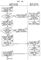
- FIG. 2 is a divided flow diagram of the method steps for controlling coordinated processing performed by message directing switch 110 serving as the "new" switch in a capping process with respect to analog switch 140 which is the "old” switch in the capping process, in response to a work order message received from provisioning system 150.
- step 202 switch 110 receives a work order message over data link 162 from provisioning system 150.
- decision step 204 transfer processor 115 makes a determination as to whether the work order message received from provisioning system 150 is in a foreign format. In this example, transfer processor 115 determines whether the work order message is in analog switch 140 or digital switch 170 format. If the outcome of step 204 is a "YES" decision, the process continues to step 206 in which the entire work order message is delivered to either switch 140 or switch 170 (i.e. a message receiving switch).
- step 208 the message receiving switch receives the work order message from switch 110 over data link 166 or data link 176 and processes the work order in step 210. (In an alternative embodiment, the message receiving switch receives the work order message directly from provisioning system 150.)
- step 211 the work order message received from provisioning system 150 is read by transfer processor 115 of message directing switch 110.
- the work order message from provisioning system 150 requires the addition of new directory number "708-555-1234" to the service base (i.e. the accumulation of all customer lines) of message directing switch 110. If the new directory number was to be added to the service base of another switch such as digital switch 170, however, switch 110 would simply facilitate a data transfer process between the switch which currently serves directory number "708-555-1234" (analog switch 140) and digital switch 170 without changing its own service base.
- transfer processor 115 makes a determination as to whether the work order message received requires a data query from another switch. Generally, all additions of directory numbers to the service base of a switch require a data query. If the outcome of decision step 212 is a "NO" decision, message directing switch 110 continues with normal provisioning in step 214. If the outcome of decision step 212 is a "YES" decision, the process continues to step 216 in which transfer processor 115 formulates a data query in the other switch format. In this example, the data query is a request for all customer data relating to directory number "708-555-1234" is formulated in analog switch 140 format, assuming that the directory number is in the analog switch's service base. The process continues to step 218 in which the data query formulated by transfer processor 115 is delivered to analog switch 140 over data link 166.
- step 220 processor 142 of analog switch 140 receives the data query from message directing switch 110.
- step 222 analog switch 140, acting in its message receiving switch capacity, finds directory number "708-555-1234" and retrieves all data relating to the directory number.
- step 224 analog switch 140 transmits the directory number data to message directing switch 110 over data link 166.
- switch 110 receives data relating to directory number "708-555-1234" from analog switch 140 and stores it in memory 113.
- the process continues (through connector A to FIG. 2B) to step 228 in which transfer processor 115 translates the data received from analog switch 140 into an appropriate switch format.
- the work order message from provisioning system 150 requires the new customer line D' to be added to the message directing switch 110 service base.
- the data received from analog switch 140 must be translated to switch 110 format. If the work order message required line D' to be added to the service base of switch 170, the translation of the data would be to digital switch 170 format.
- switch 110 uses the data received from the analog switch to process the work order message received from provisioning system 150.
- processing the work order message implies that message directing switch 110 adds new directory number "708-555-1234" and all its corresponding customer data including existing features, billing information and the recently requested ISDN service to its service base.
- processing the work order message may mean that switch 110 delivers all data corresponding to directory number "708-555-1234" over data link 176 to digital switch 170 for addition of the directory number to the digital switch 170 service base.
- step 232 message directing switch 110 sends a delete directory number "708-555-1234" message over link 166 to processor 142 of analog switch 140.
- step 234 the delete message is received by analog switch 140.
- step 236 processor 142 of analog switch 140 deletes directory number "708-555-1234" and all information relating thereto from its service base.
- step 238, analog switch 140 returns a "delete complete” message to message directing switch 110.
- step 240 message directing switch 110 receives the delete complete message.
- step 242 switch 110 reads the delete complete message from analog switch 140 and the data transfer process ends in step 244.
Abstract

Description
- This invention relates to the field of telecommunications networks and, more particularly, to coordinating data changes among central office switches in such telecommunications networks.
- Over the past decade, the demand for advanced telecommunication services has increased with population growth and technological innovation. One by-product of this demand is the frequent transfer of customer lines among central office switches. A common catalyst for the transfer of customer lines among switches is the "capping" of a central office switch. Capping is a well-known process which is instigated when an existing switch has reached its service capacity and is unable to serve the needs of the growing number of users who require additional telephone lines for equipment such as facsimile machines and personal computers. During the capping process, the growth of the switch is terminated (i.e. the switch is "capped") and additional customer lines are served by a new (usually more technologically advanced) switch. Invariably, some customers who are served by the capped switch request service features which are only available to those served by the new switch. Thus, the transfer of individual customer lines served by a capped (or "old") central office switch to a "new" central office switch is common during a capping process.
- Transferring a customer line from one central office switch to another requires manually retrieving customer line data from a first switch and entering the same data into the memory of a second switch. If adding a new service feature is the impetus for the transfer, additional data specific to the newly added service feature must also be entered into the customer data file in the second switch. Since each central office switch typically serves one or more "blocks" of directory numbers (collectively having given office codes) wherein each block of directory numbers has a unique office code, the transfer of a customer line from one switch to another switch normally implies a directory number change. To serve customers who want to retain their current directory numbers during a central office switch change over, systems exist which enable a customer line to receive incoming telephone calls having a directory number with an office code which is different than the office code of the switch by which they are served. An exemplary embodiment of such a system is disclosed in U.S. Patent 5,237,604 to Dierdre T. Hoesl entitled "Arrangement for Serving A Telephone Office Code from Two Switching Systems" which issued on August 17, 1993.
- Indeed, most customers who request new service features expect to keep their local directory number, as well as all of the existing features associated with their telephone service. To accommodate a customer's request and to ensure that there is no interruption of service, a carefully coordinated data exchange between switches is necessary.
- The prior art coordinated data exchange process is initiated by a central provisioning system which is maintained by a local exchange carrier (LEC) and serves all central office switches in a local telecommunications network. Specifically, transferring customer line data from a first central office switch to a second central office switch requires the intervention of a service technician who receives a service work order from the central provisioning system, manually retrieves all data associated with a given customer directory number from a first central office switch and then manually installs the directory number data into a second central office switch.
- The current process for customer directory number data transfer among central office switches is exemplified by the following scenario: A customer who is currently served by an analog switch decides to set up a home office. She plans to install a facsimile machine and personal computer in her home office and determines it would be beneficial to have ISDN service on her telephone line. Accordingly, the customer contacts a service representative of her local exchange carrier and requests ISDN service. Although the customer wants ISDN service, she clearly specifies that she does not want to change her current directory number of "708-555-1234". In response to the customer's request, the service representative enters a service order to provide ISDN service to the customer line identified by the directory number "708-555-1234" into a customer service operation support system (OSS).
- Eventually, the service order reaches the central provisioning system which evaluates the order and if possible (i.e. if the LEC maintains a switch capable of providing ISDN to this customer), issues a work order ticket indicating that ISDN service is to be provided to the customer line identified by the directory number "708-555-1234". In this example, assume that the central office switch which serves directory number "708-555-1234" is an analog switch which is incapable of providing ISDN service. However, the LEC also maintains a digital switch (such as the 5ESS® switch sold by AT&T Network Systems) which is capable of providing ISDN service. Thus, to provide ISDN service to this customer, the customer's line must be wired to the digital switch. Nevertheless, in accordance with the customer's request, her local directory number of "708-555-1234" and all existing features of her telephone service must not change.
- To complete this service order, a LEC technician physically wires a new customer line from a main distributing frame to the digital central office switch, he retrieves all customer data relating to directory number "708-555-1234" stored in the analog central office switch and enters the retrieved data and the newly requested ISDN feature into the digital central office switch. The technician must also program a new routing index in a separate database so that incoming calls may be properly delivered to the directory number, as is known in the art. After testing the newly established customer line to ensure that it is functioning properly, the technician severs the connection to the analog switch. Due to the manual retrieval and installation of data, the process is labor-intensive, time-consuming and prone to error. Therefore, there is a need in the art for automatically retrieving and installing customer data in a central office switch in response to a work order message received from a provisioning system in a local telecommunications network.
- This need is addressed and a technological advance is achieved in the art by a method and system which enables a message directing central office switch in a local telecommunications network to communicate with at least one other central office switch which acts as a message receiving switch for coordinating customer data exchanges.
- In one preferred embodiment of the method of the present invention, the message directing switch is a digital switching system which includes the capability to process all work order messages issued by a central provisioning system which is maintained by a local exchange carrier. More particularly, the digital switch (which may be the "new" switch in a capping scenario) serves as a receiving point for work order messages issued by the central provisioning system. Work order messages determined by the message directing switch to be in a foreign format are delivered to another switch (i.e. the message receiving switch which may be the "old" switch in a capping scenario) for processing therein. Work order messages which require coordinated data exchanges between switches are processed under the control of the message directing switch which uses a transfer processor to carry out a data transfer protocol. More particularly, in coordinated processing cases, the message directing switch formulates a data query in order to retrieve specific data from the switch acting as the message receiving switch. Once the data is received in the message directing switch, it used for normal provisioning processes. Eventually, the message directing switch directs the message receiving switch to delete the data it previously sent to the message directing switch, so that duplicate data is not maintained.
-
- FIGs. 1A and 1B show a simplified block diagram of a telecommunications network in which a preferred embodiment of the method of the invention may be practiced;
- FIG. 1C is a representation of the relationship between FIGs. 1A and 1B;
- FIGs. 2A and 2B are flow diagrams of the steps for controlling a coordinated data exchange as performed by a central office switch with message directing capabilities and another central office switch which acts as a message receiving switch in accordance with a preferred embodiment of the present invention.
- FIGs. 1A and 1B show
local telecommunications network 100 including first digitalcentral office switch 110 which has message directing capabilities and is designated the "message directing switch". Two other switches, namely, analogcentral office switch 140 and digitalcentral office switch 170 are standard central office switches which do not possess message directing capabilities and are generally referred to as "message receiving switches". In a capping scenario,message directing switch 110 is the "new" switch andanalog switch 140 is the "old" switch.Digital switch 170 is included to emphasize that any switch (analog or digital) may be a message receiving switch and thatmessage directing switch 110 may coordinate data transfers in whichdigital switch 170 is the "new" switch in a capping scenario, as explained in detail below. Although only three central office switches are shown innetwork 100, it is to be understood that an operational telecommunications network may include many more switches and thatmessage directing switch 110 may interact with a cluster of central office switches which act as message receiving switches. - Also shown is
point code converter 104 which routes incoming telephone calls from public-switched telephone network (PSTN) 102 to a central office switch inlocal telecommunications network 100 for those customer lines which retain directory numbers during switch change-overs. A detailed description of the operation ofpoint code converter 104 can be found in commonly assigned U.S. patent 5,048,081 to Gavaras et al. entitled "Arrangement for Routing Packetized Messages" which issued on September 10, 1991 (hereinafter, the Gavaras et al. patent). -
Provisioning system 150 communicates withmessage directing switch 110 viadata link 162 and in one preferred embodiment may communicate withanalog switch 140 and seconddigital switch 170 viadata link 164 anddata link 174, respectively.Message directing switch 110 andanalog switch 140 communicate with each other overintra-switch data link 166 whilemessage directing switch 110 and seconddigital switch 170 communicate with each other overintra-switch data link 176. - In a preferred embodiment,
message directing switch 110 is a digital switch with message directing capabilities such as the 5ESS® switch manufactured and sold by AT&T Network Systems. Switch 110 includes three major components: an administrative module (AM) 114 which provides system wide administration, maintenance, and resource allocation; a communications module (CM) 116 which is a hub for distributing and switching voice or digital data, control information, and synchronization signals; and a plurality of switching modules (SMs) 118 and 120 which perform local switching and control functions as well as provide interfaces to customer lines A, B, C and D'. Remoteswitching module RSM 122 is similar to switching modules 118 and 120 but it serves distant customer lines E and F via a digital loop carrier (DLC) (not shown). Hostswitching module HSM 124 is the only switching module in direct communication withPSTN 102. All communication among the elements of message directing switch 110 (including communication among all SMs and betweenAM 114 and CM 116) is accomplished over Network Control and Time (NCT) links 125. Also shown isinterface 132 which receives ported directory number routing information over message link 105 frompoint code converter 104 in accordance with the teaching of the Gavaras et al. patent. - As mentioned above,
AM 114 provides system level interfaces required to operate, administer, and maintainmessage director switch 110.AM 114 comprisesmain processor 111, memory 113 and transfer processor 115. Transfer processor 115 is the interface toprovisioning system 150 and controls all coordinated data provisioning functions amongmessage directing switch 110, andanalog switch 140 anddigital switch 170 which act in a message receiving capacity, as described in detail below. - Each switching module in
message directing switch 110 includes acontroller 127 which coordinates global functions,memory 128 for retaining specific customer line data andnetwork element 129 for routing calls to and from individual customer lines. Consistent with connections in digital switch art, all SMs are connected by two NCT links toCM 116. -
Analog switch 140 is representative of an "old" switch in a capping scenario and includes processor 142 for global functions such as common resource allocation and maintenance control,memory 144 for storing various control programs and twoswitching modules SM 146 andSM 148 which serve customer lines A' B' and C' D', respectively. Customer line D' is connected to bothSM 148 ofanalog switch 140 and SM 120 ofmessage directing switch 110. The dual line connection of line D' indicates that this line is being transferred from analog switch 140 (the "old" switch) to message directing switch 110 (the "new switch) in a process described below. Alternatively, thedigital switch 170 may be designated as the "new" switch. After the transfer process and testing of line D' onmessage directing switch 110 is complete, the connection of line D' toSM 148 ofanalog switch 140 is severed. Similar to the switching modules shown inmessage directing switch 110, each SM inanalog switch 140 includes acontroller 145, memory 147 andnetwork element 149. All communication among the elements in analogcentral office switch 140 is accomplished overdata links 141. Also shown isinterface 143 which receives routing information over message link 106 frompoint code converter 104 as described in the Gavaras et. al. patent. - Digital switch 170 (shown in simple block form) includes the same elements of
message directing switch 110 with the exception of transfer processor 115. Accordingly,digital switch 170 does not possess message directing capabilities but may act (as may any other switch) as a message receiving switch.Switch 170 communicates withmessage directing switch 110 via intra-switch data link 176, andpoint code converter 104 viadata link 107. In one preferred embodiment,digital switch 170 is in communication withcentral provisioning system 150 vialink 174. Whilemessage directing switch 110 is described the "new" switch, it is to be understood thatdigital switch 170 may serve as the "new" switch when a customer line is transferred from an analog switch (the "old" switch) to a "new" switch in a capping process. Whendigital switch 170 serves as the "new" switch, it continues to act as a message receiving switch in accordance with the principles of the present invention since it receives all provisioning messages relating to a coordinated data exchange frommessage directing switch 110. -
Provisioning system 150 includesadapter 151, CPU 152, random access memory (RAM) 154, read only memory (ROM) 156 andnon-volatile database 158.Adapter 151 enablesprovisioning system 150 to receive messages from other LEC OSSs overcommunication link 159. Work order messages directed tomessage directing switch 110,analog switch 140 ordigital switch 170 are also delivered viaadapter 151 to the appropriate switch. Communication among the elements ofprovisioning system 150 is accomplished overdata links 153. - During operation,
provisioning system 150 receives a service order from a customer service OSS (not shown) viacommunication link 159 and temporarily stores the order in RAM 154. Subsequently, CPU 152 retrieves the service order from RAM 154 and processes it using a protocol stored in ROM 156. After the service order has been processed, an appropriate work order message may be sent tocentral office switch database 158. - In one preferred embodiment,
provisioning system 150 forwards all work order messages, regardless for which central office switch the message is intended, to message directingcentral office switch 110 for processing overdata link 162. In this embodiment, transfer processor 115 ofswitch 110 receives all work order messages from the provisioning system so that a determination may be made as to whether: the work order requires processing bymessage directing switch 110 only; the work order requires processing byanalog switch 140 only; the work order requires processing bydigital switch 170 only; the work order requires coordinated processing betweenmessage directing switch 110 andanalog switch 140; the work order requires coordinated processing betweenmessage directing switch 110 anddigital switch 170; or the work order requires coordinated processing betweenanalog switch 140 anddigital switch 170. - In another preferred embodiment,
provisioning system 150 sends work order messages which only require processing byanalog switch 140 ordigital switch 170 directly to the appropriate switch viadata link 164 ordata link 174, respectively. Those work order messages which require processing bymessage directing switch 110 only, or which require coordinated processing betweenmessage directing switch 110 and any other switch intelecommunications network 100 are delivered tomessage directing switch 110 over data link 162 in the manner described above. - FIG. 2 is a divided flow diagram of the method steps for controlling coordinated processing performed by
message directing switch 110 serving as the "new" switch in a capping process with respect toanalog switch 140 which is the "old" switch in the capping process, in response to a work order message received fromprovisioning system 150. - For clarity, the above example of a customer who desires ISDN telephone service but does not want to change her current directory number of "708-555-1234" is continued. Assume that this customer is currently served by line D' of capped analog switch 140 (See FIG. 1). Since
switch 140 is an analog switch, it is incapable of providing ISDN service. Therefore, the customer's line (line D') must be manually wired to message directing switch 110 (the "new" switch) in order to receive ISDN service but must, in accordance with the customer's wishes, retain all of its existing characteristics (i.e. directory number, features and billing information). Although, in this example,message directing switch 110 also serves as the "new" switch, customer line D' could have been transferred todigital switch 170 in which case the role ofswitch 110 would simply be to facilitate a data transfer process. - The coordinated data transfer process begins in
step 202 in which switch 110 receives a work order message over data link 162 from provisioningsystem 150. Indecision step 204, transfer processor 115 makes a determination as to whether the work order message received fromprovisioning system 150 is in a foreign format. In this example, transfer processor 115 determines whether the work order message is inanalog switch 140 ordigital switch 170 format. If the outcome ofstep 204 is a "YES" decision, the process continues to step 206 in which the entire work order message is delivered to either switch 140 or switch 170 (i.e. a message receiving switch). Instep 208, the message receiving switch receives the work order message fromswitch 110 over data link 166 ordata link 176 and processes the work order instep 210. (In an alternative embodiment, the message receiving switch receives the work order message directly from provisioningsystem 150.) - If the outcome of
decision step 204 is a "NO" decision, the process continues to step 211 in which the work order message received fromprovisioning system 150 is read by transfer processor 115 ofmessage directing switch 110. In this example, the work order message from provisioningsystem 150 requires the addition of new directory number "708-555-1234" to the service base (i.e. the accumulation of all customer lines) ofmessage directing switch 110. If the new directory number was to be added to the service base of another switch such asdigital switch 170, however, switch 110 would simply facilitate a data transfer process between the switch which currently serves directory number "708-555-1234" (analog switch 140) anddigital switch 170 without changing its own service base. Indecision step 212, transfer processor 115 makes a determination as to whether the work order message received requires a data query from another switch. Generally, all additions of directory numbers to the service base of a switch require a data query. If the outcome ofdecision step 212 is a "NO" decision,message directing switch 110 continues with normal provisioning instep 214. If the outcome ofdecision step 212 is a "YES" decision, the process continues to step 216 in which transfer processor 115 formulates a data query in the other switch format. In this example, the data query is a request for all customer data relating to directory number "708-555-1234" is formulated inanalog switch 140 format, assuming that the directory number is in the analog switch's service base. The process continues to step 218 in which the data query formulated by transfer processor 115 is delivered toanalog switch 140 overdata link 166. - In
step 220, processor 142 ofanalog switch 140 receives the data query frommessage directing switch 110. The process continues to step 222 in whichanalog switch 140, acting in its message receiving switch capacity, finds directory number "708-555-1234" and retrieves all data relating to the directory number. Instep 224,analog switch 140 transmits the directory number data tomessage directing switch 110 overdata link 166. - In
step 226,switch 110 receives data relating to directory number "708-555-1234" fromanalog switch 140 and stores it in memory 113. The process continues (through connector A to FIG. 2B) to step 228 in which transfer processor 115 translates the data received fromanalog switch 140 into an appropriate switch format. In this case, the work order message from provisioningsystem 150 requires the new customer line D' to be added to themessage directing switch 110 service base. Thus, the data received fromanalog switch 140 must be translated to switch 110 format. If the work order message required line D' to be added to the service base ofswitch 170, the translation of the data would be todigital switch 170 format. Instep 230, switch 110 uses the data received from the analog switch to process the work order message received fromprovisioning system 150. In this example, processing the work order message implies thatmessage directing switch 110 adds new directory number "708-555-1234" and all its corresponding customer data including existing features, billing information and the recently requested ISDN service to its service base. In an alternative embodiment, processing the work order message may mean thatswitch 110 delivers all data corresponding to directory number "708-555-1234" overdata link 176 todigital switch 170 for addition of the directory number to thedigital switch 170 service base. - The process continues to step 232 in which
message directing switch 110 sends a delete directory number "708-555-1234" message overlink 166 to processor 142 ofanalog switch 140. In step, 234, the delete message is received byanalog switch 140. The process continues to step 236 in which processor 142 ofanalog switch 140 deletes directory number "708-555-1234" and all information relating thereto from its service base. Instep 238,analog switch 140 returns a "delete complete" message tomessage directing switch 110. Instep 240,message directing switch 110 receives the delete complete message. Instep 242, switch 110 reads the delete complete message fromanalog switch 140 and the data transfer process ends instep 244. - After the data transfer process is complete and the newly established customer line D' on
message directing switch 110 has been tested, a LEC technician severs the connection from line D' toanalog switch 140. The above-described automation of the data transfer process greatly reduces the inefficiency associated with manually retrieving data from one central switch and installing the data into another central office switch. - It is to be understood that the above-described embodiment is for illustrative purposes only and that numerous other arrangements of the invention may be devised by one skilled in the art without departing from the scope of the invention. For example, although in the above example a directory number was transferred from an analog switch to the message directing switch, it is envisioned that a message directing switch could also direct a transfer of directory number data from its service base to any other switch.
Claims (14)
- In a telecommunication network comprising a plurality of switches and a central provisioning system, a method for automatically coordinating data changes among switches comprises :receiving a work order message from the central provisioning system at a message directing switch;determining that the work order message received requires the message directing switch to coordinate a data transfer process involving at least one message receiving switch;formulating a data query for delivery to the message receiving switch;translating data received in response to the data query in the message directing switch; andusing the translated data received to process the data changes.
- The method of claim 1 and further comprising:determining in the message directing switch that the work order message received is in a foreign switch format;identifying the format of the work order message; anddelivering the work order message to a message receiving switch.
- The method of claim 1 wherein the step of formulating a query in the message directing switch for delivery to at least one message receiving switch comprises
formulating a request for all data relating to a specific directory number in a transfer processor of the message directing switch. - The method of claim 1 wherein the step of translating data received in response to the data query comprises
using a transfer processor in the message directing switch to translate data received from the message receiving switch into a format other than message directing switch format. - The method of claim 1 wherein the step of using the data received to process the data changes comprises the steps of:adding the data received from the message receiving switch to a service base of the message directing switch; anddeleting the data received from the message receiving switch from a service base of the message receiving switch.
- The method of claim 1 wherein the step of using the data received to process the data changes comprises the step of:
delivering the data received from the message receiving switch for addition to a service base of another switch. - In a telecommunication system comprising a plurality of central office switches interconnected by intra-switch links and a central provisioning system, wherein the central provisioning system communicates with each central office switch over a specific data link, a method for coordinating data transfers among at least two central office switches comprises:receiving, via one of the specific data links, a work order message from the central provisioning system at a first switch, wherein the first switch is a message directing switch;formulating a data query message in the first switch for delivery to a second switch;transmitting data from the second switch over one of the intra-switch data links to the first switch in response to the data query from the first switch;processing the work order message in the first switch using data received from the second switch; anddeleting data in the second switch in response to a message received from the first switch.
- The method of claim 7 wherein the step of formulating a data query in the first switch comprises using a transfer processor in the first switch.
- The method of claim 7 wherein the step of processing the work order message in the first switch using data received from the second switch comprises:
adding a directory number and all associated feature data to a service base of the first switch. - The method of claim 7 wherein the step of processing the work order message in the first switch using data received from the second switch comprises
adding a directory number and all associated feature data to a service base of a third switch. - The method of claim 7 wherein the step of deleting data in the second switch in response to a message received from the first switch comprises
deleting directory number data from a service base of the second switch. - A telecommunications network comprising:a message directing switch including a transfer processor for coordinating data transfers among a plurality of switches;at least one message receiving switch in communication with the message directing switch, wherein each message receiving switch includes means for receiving data queries from the message directing switch;a central provisioning system including a data link to the message directing switch for transmitting work order messages to the message directing switch; anda point code converter in communication with the message directing switch and each message receiving switches for routing incoming calls.
- The telecommunications network of claim 12 and further comprising a data link between the central provisioning system and each message receiving switch.
- The telecommunications network of claim 12 wherein the transfer processor translates messages into message receiving switch format.
Applications Claiming Priority (2)
| Application Number | Priority Date | Filing Date | Title |
|---|---|---|---|
| US08/448,954 US5661789A (en) | 1995-05-24 | 1995-05-24 | Method for coordinating data changes among central office switches |
| US448954 | 1995-05-24 |
Publications (3)
| Publication Number | Publication Date |
|---|---|
| EP0744873A2 true EP0744873A2 (en) | 1996-11-27 |
| EP0744873A3 EP0744873A3 (en) | 1999-10-06 |
| EP0744873B1 EP0744873B1 (en) | 2003-02-26 |
Family
ID=23782296
Family Applications (1)
| Application Number | Title | Priority Date | Filing Date |
|---|---|---|---|
| EP96303404A Expired - Lifetime EP0744873B1 (en) | 1995-05-24 | 1996-05-14 | Method for coordinating data changes among central office switches |
Country Status (4)
| Country | Link |
|---|---|
| US (1) | US5661789A (en) |
| EP (1) | EP0744873B1 (en) |
| CA (1) | CA2172649C (en) |
| DE (1) | DE69626339D1 (en) |
Families Citing this family (6)
| Publication number | Priority date | Publication date | Assignee | Title |
|---|---|---|---|---|
| US5838783A (en) * | 1995-12-27 | 1998-11-17 | Lucent Technologies, Inc. | Smart directory management |
| US6301351B1 (en) | 1998-04-08 | 2001-10-09 | Sbc Technology Resources Inc. | Device and method for transferring unbundled network elements between local exchange carriers |
| DE19952607B4 (en) * | 1999-11-02 | 2009-04-30 | Deutsche Telekom Ag | A method and communication network for providing one or more features to any subscriber |
| US7360153B1 (en) * | 2000-01-17 | 2008-04-15 | Lucent Technologies Inc. | Method and apparatus for importing digital switching system data into a spreadsheet program |
| US7349533B2 (en) * | 2002-10-01 | 2008-03-25 | Nortel Networks Limited | Telephony transitioning system |
| WO2006065176A1 (en) * | 2004-12-14 | 2006-06-22 | Telefonaktiebolaget Lm Ericsson (Publ) | Method and apparatus for controlling a provisioning process in a telecommunications system |
Citations (4)
| Publication number | Priority date | Publication date | Assignee | Title |
|---|---|---|---|---|
| JPS59174061A (en) * | 1983-03-23 | 1984-10-02 | Hitachi Ltd | Overlay communication network |
| EP0200353A2 (en) * | 1985-04-27 | 1986-11-05 | Stc Plc | Telecommunication system |
| US4754479A (en) * | 1986-09-17 | 1988-06-28 | American Telephone And Telegraph Company | Station number portability |
| EP0510861A2 (en) * | 1991-04-24 | 1992-10-28 | AT&T Corp. | Method of rerouting telecommunications traffic |
Family Cites Families (5)
| Publication number | Priority date | Publication date | Assignee | Title |
|---|---|---|---|---|
| US4899373A (en) * | 1986-11-28 | 1990-02-06 | American Telephone And Telegraph Company At&T Bell Laboratories | Method and apparatus for providing personalized telephone subscriber features at remote locations |
| US5048081A (en) * | 1989-12-28 | 1991-09-10 | At&T Bell Laboratories | Arrangement for routing packetized messages |
| US5237604A (en) * | 1991-06-28 | 1993-08-17 | At&T Bell Laboratories | Arrangement for serving a telephone office code from two switching systems |
| US5347564A (en) * | 1991-12-20 | 1994-09-13 | The Chesapeake And Potomac Telephone Company Of Maryland | Automated translation input system |
| US5497412A (en) * | 1994-04-07 | 1996-03-05 | Gte Telecommunication Services Incorporated | Enhanced call delivery system for roaming cellular subscribers |
-
1995
- 1995-05-24 US US08/448,954 patent/US5661789A/en not_active Expired - Fee Related
-
1996
- 1996-03-26 CA CA002172649A patent/CA2172649C/en not_active Expired - Fee Related
- 1996-05-14 EP EP96303404A patent/EP0744873B1/en not_active Expired - Lifetime
- 1996-05-14 DE DE69626339T patent/DE69626339D1/en not_active Expired - Lifetime
Patent Citations (4)
| Publication number | Priority date | Publication date | Assignee | Title |
|---|---|---|---|---|
| JPS59174061A (en) * | 1983-03-23 | 1984-10-02 | Hitachi Ltd | Overlay communication network |
| EP0200353A2 (en) * | 1985-04-27 | 1986-11-05 | Stc Plc | Telecommunication system |
| US4754479A (en) * | 1986-09-17 | 1988-06-28 | American Telephone And Telegraph Company | Station number portability |
| EP0510861A2 (en) * | 1991-04-24 | 1992-10-28 | AT&T Corp. | Method of rerouting telecommunications traffic |
Non-Patent Citations (2)
| Title |
|---|
| BISHOP T: "FREEING THE NETWORK FOR COMPETITION" TELECOMMUNICATIONS, vol. 29, no. 4, 1 April 1995 (1995-04-01), page 75, 77/78, 80 XP002037911 ISSN: 0040-2494 * |
| PATENT ABSTRACTS OF JAPAN vol. 009, no. 031 (E-295), 9 February 1985 (1985-02-09) & JP 59 174061 A (HITACHI SEISAKUSHO KK), 2 October 1984 (1984-10-02) * |
Also Published As
| Publication number | Publication date |
|---|---|
| CA2172649C (en) | 1999-09-07 |
| DE69626339D1 (en) | 2003-04-03 |
| EP0744873A3 (en) | 1999-10-06 |
| EP0744873B1 (en) | 2003-02-26 |
| CA2172649A1 (en) | 1996-11-25 |
| US5661789A (en) | 1997-08-26 |
Similar Documents
| Publication | Publication Date | Title |
|---|---|---|
| EP0520688B1 (en) | Method of rerouting telecommunications traffic | |
| EP0228204B1 (en) | Architecture for distributed control telecommunication switching systems | |
| US6356756B1 (en) | Method and system for routing calls to a wireless telecommunications services platform | |
| CA2179498C (en) | A network-based telephone system having interactive capabilities | |
| US5633922A (en) | Process and apparatus for restarting call routing in a telephone network | |
| JP2635163B2 (en) | Network service provision method | |
| EP0732661A1 (en) | Method and system for archiving information on a communication network | |
| EP0708570A2 (en) | Completing telecommunications calls in a competitive environment | |
| EP0590863A2 (en) | Private branch exchange networks | |
| EP0956718B1 (en) | Call management in a wireless telecommunications system | |
| JPS6298846A (en) | Call load balancing of automatic call distribution telephoneservice | |
| EP0852874B1 (en) | System for incremental redistribution of telephony applications computing workload | |
| EP0763955B1 (en) | Method for prohibiting continual routing of a call between central office switches due to translation error | |
| MXPA96004119A (en) | Method to prevent continuous direction of a call between centrals due to error transfer details | |
| US5661789A (en) | Method for coordinating data changes among central office switches | |
| EP0559315A2 (en) | Telecommunications service provision equipment transfer | |
| AU750007B2 (en) | Radio terminal operation data write method in private mobile communication system | |
| US6038228A (en) | Processing call information within a telecommunications network | |
| EP1492359A1 (en) | Processing of signalling messages according to one of a plurality of protocol stacks | |
| US6487216B1 (en) | Management of a telecommunications system | |
| US6219338B1 (en) | Method of establishing a connection, as well as exchange, service computer and communications network | |
| GB2329790A (en) | Maintaining information concerning subscriber terminals within a call routing system of a telecommunications system | |
| US20020016832A1 (en) | Method of establishing a connection, as well as an exchange and a service control point | |
| KR930010253B1 (en) | Method of compiling a called number of full electronic exchange | |
| KR100438070B1 (en) | Method for Network Management Service By Primary Rate Interface Network In Exchanger |
Legal Events
| Date | Code | Title | Description |
|---|---|---|---|
| PUAI | Public reference made under article 153(3) epc to a published international application that has entered the european phase |
Free format text: ORIGINAL CODE: 0009012 |
|
| AK | Designated contracting states |
Kind code of ref document: A2 Designated state(s): DE FR GB |
|
| PUAL | Search report despatched |
Free format text: ORIGINAL CODE: 0009013 |
|
| AK | Designated contracting states |
Kind code of ref document: A3 Designated state(s): DE FR GB |
|
| 17P | Request for examination filed |
Effective date: 20000323 |
|
| 17Q | First examination report despatched |
Effective date: 20011008 |
|
| GRAG | Despatch of communication of intention to grant |
Free format text: ORIGINAL CODE: EPIDOS AGRA |
|
| GRAG | Despatch of communication of intention to grant |
Free format text: ORIGINAL CODE: EPIDOS AGRA |
|
| GRAH | Despatch of communication of intention to grant a patent |
Free format text: ORIGINAL CODE: EPIDOS IGRA |
|
| GRAH | Despatch of communication of intention to grant a patent |
Free format text: ORIGINAL CODE: EPIDOS IGRA |
|
| GRAA | (expected) grant |
Free format text: ORIGINAL CODE: 0009210 |
|
| AK | Designated contracting states |
Designated state(s): DE FR GB |
|
| REG | Reference to a national code |
Ref country code: GB Ref legal event code: FG4D |
|
| REF | Corresponds to: |
Ref document number: 69626339 Country of ref document: DE Date of ref document: 20030403 Kind code of ref document: P |
|
| PG25 | Lapsed in a contracting state [announced via postgrant information from national office to epo] |
Ref country code: GB Free format text: LAPSE BECAUSE OF NON-PAYMENT OF DUE FEES Effective date: 20030526 |
|
| PG25 | Lapsed in a contracting state [announced via postgrant information from national office to epo] |
Ref country code: DE Free format text: LAPSE BECAUSE OF FAILURE TO SUBMIT A TRANSLATION OF THE DESCRIPTION OR TO PAY THE FEE WITHIN THE PRESCRIBED TIME-LIMIT Effective date: 20030527 |
|
| ET | Fr: translation filed | ||
| PLBE | No opposition filed within time limit |
Free format text: ORIGINAL CODE: 0009261 |
|
| STAA | Information on the status of an ep patent application or granted ep patent |
Free format text: STATUS: NO OPPOSITION FILED WITHIN TIME LIMIT |
|
| GBPC | Gb: european patent ceased through non-payment of renewal fee |
Effective date: 20030526 |
|
| 26N | No opposition filed |
Effective date: 20031127 |
|
| REG | Reference to a national code |
Ref country code: FR Ref legal event code: ST Effective date: 20080229 |
|
| PG25 | Lapsed in a contracting state [announced via postgrant information from national office to epo] |
Ref country code: FR Free format text: LAPSE BECAUSE OF NON-PAYMENT OF DUE FEES Effective date: 20030531 |