EP0745926A1 - Convertible peripheral input device - Google Patents
Convertible peripheral input device Download PDFInfo
- Publication number
- EP0745926A1 EP0745926A1 EP96303872A EP96303872A EP0745926A1 EP 0745926 A1 EP0745926 A1 EP 0745926A1 EP 96303872 A EP96303872 A EP 96303872A EP 96303872 A EP96303872 A EP 96303872A EP 0745926 A1 EP0745926 A1 EP 0745926A1
- Authority
- EP
- European Patent Office
- Prior art keywords
- input device
- control pad
- hinge member
- peripheral input
- multiaxis
- Prior art date
- Legal status (The legal status is an assumption and is not a legal conclusion. Google has not performed a legal analysis and makes no representation as to the accuracy of the status listed.)
- Granted
Links
Images


Classifications
-
- G—PHYSICS
- G06—COMPUTING; CALCULATING OR COUNTING
- G06F—ELECTRIC DIGITAL DATA PROCESSING
- G06F3/00—Input arrangements for transferring data to be processed into a form capable of being handled by the computer; Output arrangements for transferring data from processing unit to output unit, e.g. interface arrangements
- G06F3/01—Input arrangements or combined input and output arrangements for interaction between user and computer
- G06F3/03—Arrangements for converting the position or the displacement of a member into a coded form
- G06F3/033—Pointing devices displaced or positioned by the user, e.g. mice, trackballs, pens or joysticks; Accessories therefor
- G06F3/0338—Pointing devices displaced or positioned by the user, e.g. mice, trackballs, pens or joysticks; Accessories therefor with detection of limited linear or angular displacement of an operating part of the device from a neutral position, e.g. isotonic or isometric joysticks
-
- A—HUMAN NECESSITIES
- A63—SPORTS; GAMES; AMUSEMENTS
- A63F—CARD, BOARD, OR ROULETTE GAMES; INDOOR GAMES USING SMALL MOVING PLAYING BODIES; VIDEO GAMES; GAMES NOT OTHERWISE PROVIDED FOR
- A63F13/00—Video games, i.e. games using an electronically generated display having two or more dimensions
- A63F13/20—Input arrangements for video game devices
- A63F13/24—Constructional details thereof, e.g. game controllers with detachable joystick handles
-
- A—HUMAN NECESSITIES
- A63—SPORTS; GAMES; AMUSEMENTS
- A63F—CARD, BOARD, OR ROULETTE GAMES; INDOOR GAMES USING SMALL MOVING PLAYING BODIES; VIDEO GAMES; GAMES NOT OTHERWISE PROVIDED FOR
- A63F13/00—Video games, i.e. games using an electronically generated display having two or more dimensions
- A63F13/40—Processing input control signals of video game devices, e.g. signals generated by the player or derived from the environment
- A63F13/42—Processing input control signals of video game devices, e.g. signals generated by the player or derived from the environment by mapping the input signals into game commands, e.g. mapping the displacement of a stylus on a touch screen to the steering angle of a virtual vehicle
- A63F13/428—Processing input control signals of video game devices, e.g. signals generated by the player or derived from the environment by mapping the input signals into game commands, e.g. mapping the displacement of a stylus on a touch screen to the steering angle of a virtual vehicle involving motion or position input signals, e.g. signals representing the rotation of an input controller or a player's arm motions sensed by accelerometers or gyroscopes
-
- G—PHYSICS
- G05—CONTROLLING; REGULATING
- G05G—CONTROL DEVICES OR SYSTEMS INSOFAR AS CHARACTERISED BY MECHANICAL FEATURES ONLY
- G05G5/00—Means for preventing, limiting or returning the movements of parts of a control mechanism, e.g. locking controlling member
- G05G5/06—Means for preventing, limiting or returning the movements of parts of a control mechanism, e.g. locking controlling member for holding members in one or a limited number of definite positions only
- G05G5/08—Interlocking of members, e.g. locking member in a particular position before or during the movement of another member
-
- G—PHYSICS
- G05—CONTROLLING; REGULATING
- G05G—CONTROL DEVICES OR SYSTEMS INSOFAR AS CHARACTERISED BY MECHANICAL FEATURES ONLY
- G05G9/00—Manually-actuated control mechanisms provided with one single controlling member co-operating with two or more controlled members, e.g. selectively, simultaneously
- G05G9/02—Manually-actuated control mechanisms provided with one single controlling member co-operating with two or more controlled members, e.g. selectively, simultaneously the controlling member being movable in different independent ways, movement in each individual way actuating one controlled member only
- G05G9/04—Manually-actuated control mechanisms provided with one single controlling member co-operating with two or more controlled members, e.g. selectively, simultaneously the controlling member being movable in different independent ways, movement in each individual way actuating one controlled member only in which movement in two or more ways can occur simultaneously
- G05G9/047—Manually-actuated control mechanisms provided with one single controlling member co-operating with two or more controlled members, e.g. selectively, simultaneously the controlling member being movable in different independent ways, movement in each individual way actuating one controlled member only in which movement in two or more ways can occur simultaneously the controlling member being movable by hand about orthogonal axes, e.g. joysticks
-
- G—PHYSICS
- G06—COMPUTING; CALCULATING OR COUNTING
- G06F—ELECTRIC DIGITAL DATA PROCESSING
- G06F3/00—Input arrangements for transferring data to be processed into a form capable of being handled by the computer; Output arrangements for transferring data from processing unit to output unit, e.g. interface arrangements
- G06F3/01—Input arrangements or combined input and output arrangements for interaction between user and computer
- G06F3/02—Input arrangements using manually operated switches, e.g. using keyboards or dials
- G06F3/0202—Constructional details or processes of manufacture of the input device
- G06F3/021—Arrangements integrating additional peripherals in a keyboard, e.g. card or barcode reader, optical scanner
- G06F3/0213—Arrangements providing an integrated pointing device in a keyboard, e.g. trackball, mini-joystick
-
- G—PHYSICS
- G06—COMPUTING; CALCULATING OR COUNTING
- G06F—ELECTRIC DIGITAL DATA PROCESSING
- G06F3/00—Input arrangements for transferring data to be processed into a form capable of being handled by the computer; Output arrangements for transferring data from processing unit to output unit, e.g. interface arrangements
- G06F3/01—Input arrangements or combined input and output arrangements for interaction between user and computer
- G06F3/03—Arrangements for converting the position or the displacement of a member into a coded form
- G06F3/033—Pointing devices displaced or positioned by the user, e.g. mice, trackballs, pens or joysticks; Accessories therefor
- G06F3/0354—Pointing devices displaced or positioned by the user, e.g. mice, trackballs, pens or joysticks; Accessories therefor with detection of 2D relative movements between the device, or an operating part thereof, and a plane or surface, e.g. 2D mice, trackballs, pens or pucks
- G06F3/03543—Mice or pucks
-
- A—HUMAN NECESSITIES
- A63—SPORTS; GAMES; AMUSEMENTS
- A63F—CARD, BOARD, OR ROULETTE GAMES; INDOOR GAMES USING SMALL MOVING PLAYING BODIES; VIDEO GAMES; GAMES NOT OTHERWISE PROVIDED FOR
- A63F2300/00—Features of games using an electronically generated display having two or more dimensions, e.g. on a television screen, showing representations related to the game
- A63F2300/10—Features of games using an electronically generated display having two or more dimensions, e.g. on a television screen, showing representations related to the game characterized by input arrangements for converting player-generated signals into game device control signals
- A63F2300/1006—Features of games using an electronically generated display having two or more dimensions, e.g. on a television screen, showing representations related to the game characterized by input arrangements for converting player-generated signals into game device control signals having additional degrees of freedom
-
- A—HUMAN NECESSITIES
- A63—SPORTS; GAMES; AMUSEMENTS
- A63F—CARD, BOARD, OR ROULETTE GAMES; INDOOR GAMES USING SMALL MOVING PLAYING BODIES; VIDEO GAMES; GAMES NOT OTHERWISE PROVIDED FOR
- A63F2300/00—Features of games using an electronically generated display having two or more dimensions, e.g. on a television screen, showing representations related to the game
- A63F2300/10—Features of games using an electronically generated display having two or more dimensions, e.g. on a television screen, showing representations related to the game characterized by input arrangements for converting player-generated signals into game device control signals
- A63F2300/1043—Features of games using an electronically generated display having two or more dimensions, e.g. on a television screen, showing representations related to the game characterized by input arrangements for converting player-generated signals into game device control signals being characterized by constructional details
-
- G—PHYSICS
- G05—CONTROLLING; REGULATING
- G05G—CONTROL DEVICES OR SYSTEMS INSOFAR AS CHARACTERISED BY MECHANICAL FEATURES ONLY
- G05G9/00—Manually-actuated control mechanisms provided with one single controlling member co-operating with two or more controlled members, e.g. selectively, simultaneously
- G05G9/02—Manually-actuated control mechanisms provided with one single controlling member co-operating with two or more controlled members, e.g. selectively, simultaneously the controlling member being movable in different independent ways, movement in each individual way actuating one controlled member only
- G05G9/04—Manually-actuated control mechanisms provided with one single controlling member co-operating with two or more controlled members, e.g. selectively, simultaneously the controlling member being movable in different independent ways, movement in each individual way actuating one controlled member only in which movement in two or more ways can occur simultaneously
- G05G9/047—Manually-actuated control mechanisms provided with one single controlling member co-operating with two or more controlled members, e.g. selectively, simultaneously the controlling member being movable in different independent ways, movement in each individual way actuating one controlled member only in which movement in two or more ways can occur simultaneously the controlling member being movable by hand about orthogonal axes, e.g. joysticks
- G05G2009/04774—Manually-actuated control mechanisms provided with one single controlling member co-operating with two or more controlled members, e.g. selectively, simultaneously the controlling member being movable in different independent ways, movement in each individual way actuating one controlled member only in which movement in two or more ways can occur simultaneously the controlling member being movable by hand about orthogonal axes, e.g. joysticks with additional switches or sensors on the handle
-
- H—ELECTRICITY
- H01—ELECTRIC ELEMENTS
- H01H—ELECTRIC SWITCHES; RELAYS; SELECTORS; EMERGENCY PROTECTIVE DEVICES
- H01H2217/00—Facilitation of operation; Human engineering
- H01H2217/048—Facilitation of operation; Human engineering adapted for operation by left- and right-handed
Definitions
- the present invention generally relates to the use of peripheral input devices for use with computers, including videogame consoles, and more particularly to the use of a hinge mechanism which permits conversion of a peripheral device from right-handed use to left-handed use.
- a more specific object of the present invention is to provide a system of combining peripheral input devices which can be easily and routinely convertible from right-handed use to left-handed use, and back to the original configuration.
- a convertible peripheral input device comprising:
- the hinge mechanism has two points of rotation.
- the first is on the bottom surface of the control pad. This rotation point allows the hinge mechanism to rotate from one side of the control pad to the other, operating in a semicircular arch with the bottom surface of the control pad acting as the diameter of the arch.
- the second rotation point for the hinge mechanism is located at the bottom surface of the multiaxis input device. This rotation point allows the multiaxis input device to rotate 180 degrees relative to the plane of the bottom surface of the control pad. Based upon these two rotational degrees of freedom, the hinge mechanism allows the multiaxis input device to be moved from one side of the control pad to the other without having to completely disconnect the multiaxis input device from the control pad.
- the control pad has a first opening in the bottom surface thereof, and the first end of the hinge member has a first protrusion being fit in the first opening so that the hinge member is rotatable with respect to the bottom surface of the control pad.
- the hinge member may further comprise a third end extending in the same direction as the first end and a fourth end extending in the same direction as the second end, the control pad having a second opening in the bottom surface thereof, the third end having a second protrusion being fit in the second opening of the control pad.
- the control pad has a first protrusion in the bottom surface thereof, and the first end of the hinge member has a first recess being fit to the first protrusion so that the hinge member is rotatable with respect to the bottom surface of the control pad.
- the hinge member may further comprise a third end extending in the same direction with the first end and a fourth end extending in the same direction as the second end, the control pad having a second protrusion in the bottom surface thereof, the third end having a second recess being fit to the second protrusion of the control pad.
- the control pad includes two raised portions each having a sidewall and a space formed between the sidewalls of the two raised portions in the bottom surface of the control pad, each of the sidewalls being perpendicular to the bottom surface of the control pad and having a slot-shaped opening therein, each of the raised potions having a notch adjacent to and continuous with the respective slot-shaped opening, the hinge member having a third end extending in the same direction as the first end, each of the first end and the third end having a protrusion being inserted into the respective notches and slot-shaped openings so that the protrusions are rotatable within the slot-shaped openings and movable along an extending direction of the slot-shaped openings.
- Each of the protrusions of the hinge member may comprise a cylindrical portion being fit in the respective one of the slot-shaped openings and a rectangular raised portion being inserted into the respective one of the notches.
- the convertible peripheral input device may further comprise a securing device to rigidly secure the hinge member to the control pad.
- the securing device may comprise a screw fastened to the control pad through the hinge member.
- the multiaxis input device may be a joystick, a trackball or a mouse controller.
- the present invention is described below with reference to a convertible peripheral input device available for use with the Sega SaturnTM Videogame system.
- the purpose of this description with reference to the particularly preferred embodiment is to illustrate the present invention, and it is not intended to limit the scope of the claims appended hereto.
- peripheral input device and control pad are used more broadly than as used in connection with the preferred embodiments.
- the hinge mechanism of the present invention could be used to rotate a mouse controller (a multiaxis input device) from one side of a keyboard (control pad) to the other side of the keyboard.
- the multiaxis input device includes a trackball as an input device.
- FIG.1 shows a convertible peripheral input device 10 according to a first embodiment of the present invention.
- the convertible peripheral input device 10 comprises a control pad 12 and a three-axis joystick 14.
- the control pad 12 has buttons and keys for inputting various data to the video console.
- the joystick has a thumb-operated z-axis controller 18. The two devices are joined along the control pad body edge 20 and the joystick base edge 22.
- FIG.2 is a plane view of the convertible peripheral input device in a state where the joystick 14 is arranged to be operated by a right hand.
- FIG.3 is a bottom view of the convertible peripheral input device 10 in the state shown in FIG.2.
- the joystick 14 is located on the right-hand side of the control pad 12, the joystick 14 can be located on the left hand side of the control pad 12, as will be described later.
- the control pad and the joystick 14 are coupled by a hinge mechanism including a hinge member 42. The change of the location of the joystick 14 relative to the control pad 12 can be achieved by an operation of the hinge mechanism.
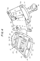
- FIG.4 is an exploded perspective view of the convertible peripheral input device 10 in a state where the joystick 14 is separated from the control pad 12.
- the bottom surface of the control pad 12 has a first channel 24 and second channel 26.
- the first and second channels are substantially parallel to each other, and extend between opposite sides of the body of the control pad 12. These channels 24 and 26 may be slightly curved depending on the angle of the control pad body edge 20.
- the bottom surface of the control pad 12 also has an input port protector 28 which provides the space necessary for a first input port 30 and a second input port 32.
- two joysticks 14 can be electrically connected to the single control pad 12 which is provided with a microprocessor by the first and second input ports 30 and 32.
- first raised portion 34 and a second raised portion 39 Adjacent to the input port protector 28, on either side of the channels 24 and 26, respectively, there are a first raised portion 34 and a second raised portion 39. Stabilizers 35, in the nature of rubber disks, are provided on the first and second raised portions 34 and 39 to insure that the control pad 12 rests stably and flatly on the playing surface.
- the first and second raised portions 34 and 39 are preferably of greater height than the input port protector 28, although this is not essential.
- first channel 24 In one of the side walls defining the first channel 24, there is a slot-shaped aperture 36. On the first raise portion 34 there is a notch 38 which is continuous with the slot-shaped aperture 36. Another notch 40 is seen in the second raised portion 39. These apertures/notches cooperate with protrusions extending from the hinge member 42.
- the hinge mechanism including the hinge member 42 has two points of rotation.
- the hinge member 42 is rotatably fixed to the base of the joystick 14 by coupling mechanisms 44 and 46.
- the coupling mechanisms 44 and 46 can consist of either protrusions in sidewalls formed in a bottom surface of the joystick 14 mating with apertures in the hinge mechanism, or it can be reversed, where the protrusions extend out from the hinge mechanism for mating with apertures in the sidewalls in the bottom surface of the joystick 14.
- At the other end of the hinge member 42 is the second point of rotation under the control pad 12.
- the hinge member 42 has first and second hinge protrusions 48 and 50, respectively.
- the protrusions 48 and 50 mate with apertures/notches 36/38 and 40, respectively, to provide the second point of rotation.
- the slot-shaped aperture/notch approach permits the hinge mechanism/joystick to be completely removed from the control pad, when they are not wanted.
- bottom surface of the base of the joystick 14 is also provided with stabilizers 56. Additionally, screws 52 and 54 are provided for securing the hinge member 42 to the control pad 12 and the joystick 14, respectively.
- FIGS.5A through 5D show the sequence of positions used in the installation of the hinge member 42 into the aperture/notch 36/38.
- FIG.5A shows the hinge member 42 in a position substantially perpendicular to the bottom surface of the control pad 12.
- the hinge protrusion 48 has a rectangular raised portion which is adapted to be received within the notch 38, allowing the hinge mechanism to be lowered, in a direction indicated by an arrow in FIG.5A, into the first channel 24 so that the cylindrical portions of the protrusion 48 is aligned with the slot-shaped aperture 36.
- FIG.5B shows the hinge mechanism being lowered into a position within the slot-shaped aperture 36.
- the hinge member 42 is rotated from the 12 o'clock position to the 3 o'clock position. This rotation causes the rectangular raised portion of the protrusion 48 to be locked within the notch 38 because the notch is dimensioned to receive the rectangular raised portion when it is vertical and not when it is horizontal.
- the protrusion 48 can be pulled in the direction of the arrow in FIG.5D to position the hinge member 42 and the control pad 12 and the joystick 14 to be secured along adjacent edges 20 and 22.
- the protrusion 50 is inserted into the notch 40 formed in the second raised portion 39 in the same manner and at the same time as the insertion of the protrusion 48.
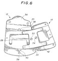
- FIG. 6 The final assembly is shown in FIG. 6.
- the hinge member 42 secures the base of the joystick 14 along the edge 20 of the control pad 12 and screws 52 and 54 are in place to secure the two devices relative to each other.
- FIG.6 also provides a good view for describing how the joystick 14 could be rotated from its place along the control pad edge 20 to a position on the opposite side of the control pad 12.
- the hinge member 42 can be rotated 180 degrees about the protrusions 48 and 50 with respect to the bottom surface of the control pad 12. This rotation would cause the joystick 14 to face down 180 degrees out of phase from the desired operating position.
- the joystick 14 is also rotated 180 degrees about the coupling mechanisms 44 and 46 to cause the joystick 14 to face upward.
- the convertible peripheral input device 10 is changed from a control pad 12 with a joystick 14 in the left-handed operating position to a control pad 12 with a joystick 14 in the right-handed operating position.
- the screws 52 and 54 can be used to secure the control pad 12 and the joystick 14 in this configuration.
- two joysticks 14 can be attached to the single control pad 12 on the left and right sides thereof, if it is desired. That is, an additional joystick can be installed on the opposite side so as to form a six-axis input device.
- the input ports 30 and 32 are used to electrically connect two joysticks to the control pad 12.
- the second embodiment of the present invention is limited to installing only a single joystick to the control pad 12.
- FIG.7 is a perspective view of a hinge member 58 which is a part of a convertible peripheral input device according to the second embodiment of the present invention.
- the basic structure of the second embodiment is the same as that of the above-mentioned first embodiment, and descriptions thereof will be omitted.
- the hinge member 58 shown in FIG.7 has a first end 60, a second end 62, a third end 64 and a fourth end 66.
- the first end 60 and the third end 64 extend in the same direction, and the second end 62 and the fourth end 66 extend in a direction opposite to the direction of the first and third ends 60 and 64.
- the first end 60, the second end 62, the third end 64 and the fourth end 66 have recesses 60a, 62a, 64a and 66a, respectively (the recesses 64a and 66a do not appear in the figure).
- the second end 62 and the fourth end 66 are rotatably mounted in the bottom of the joystick 14 in a similar manner as that of the first embodiment. That is, the recesses 62a and 66a fit on respective protrusions provided in the bottom of the joystick 14.
- the slot-shaped aperture 36 and the notches 38 and 40 are not provided as is in the first embodiment.
- protrusions are formed in the center of the sidewalls of the channels 24 and 26 where the slot-shaped apertures 36 were formed. The protrusions are inserted into the respective recesses 60a and 64a of the hinge member 58, and thereby the hinge member 58 is rotatable 180 degrees with respect to the bottom of the control pad 12. Accordingly, in the second embodiment, only a single joystick can be installed to the control pad to be situated either to the right or left of the control pad, but a structure of the hinge mechanism is simple as compared to that of the first embodiment.
Abstract
Description
- The present invention generally relates to the use of peripheral input devices for use with computers, including videogame consoles, and more particularly to the use of a hinge mechanism which permits conversion of a peripheral device from right-handed use to left-handed use.
- There is a large variety of computer input devices which can be used alone or in combination with other peripheral input devices. In common use are a joystick and a control pad with a raster-based computer game. Also commonly used are a keyboard and a mouse controller during operation of a personal computer. When these devices are used in combination, they are arranged to suit the user's orientation and preference. Some users prefer to use the mouse controller on the right hand side of the keyboard. Other users prefer it to be located to the left of the keyboard. The physical attachment of the two peripheral devices, or even a decision whether to attach them to each other at all, represents a significant choice. Moreover, the original positioning may make a desired combination of the devices ergonomically difficult.
- It is a general object of the present invention to provide an improved and useful convertible peripheral input device in which the above-mentioned problems are eliminated.
- A more specific object of the present invention is to provide a system of combining peripheral input devices which can be easily and routinely convertible from right-handed use to left-handed use, and back to the original configuration.
- In order to achieve the above-mentioned objects, there is provided according to the present invention a convertible peripheral input device comprising:
- a control pad having a bottom surface;
- a multiaxis input device having a bottom surface; and
- a hinge member having a first end and a second end opposite to the first end, the hinge member being rotatably mounted to the control pad substantially 180 degrees with respect to the bottom surface of the control pad at the first end, the hinge member being rotatably mounted to the multiaxis input device substantially 180 degrees with respect to the bottom surface of the multiaxis input device at the second end,
- wherein the multiaxis input device is movable to either the right or left side of the control pad.
- According to the present invention, the hinge mechanism has two points of rotation. The first is on the bottom surface of the control pad. This rotation point allows the hinge mechanism to rotate from one side of the control pad to the other, operating in a semicircular arch with the bottom surface of the control pad acting as the diameter of the arch. The second rotation point for the hinge mechanism is located at the bottom surface of the multiaxis input device. This rotation point allows the multiaxis input device to rotate 180 degrees relative to the plane of the bottom surface of the control pad. Based upon these two rotational degrees of freedom, the hinge mechanism allows the multiaxis input device to be moved from one side of the control pad to the other without having to completely disconnect the multiaxis input device from the control pad.
- In one embodiment of the present invention, the control pad has a first opening in the bottom surface thereof, and the first end of the hinge member has a first protrusion being fit in the first opening so that the hinge member is rotatable with respect to the bottom surface of the control pad. The hinge member may further comprise a third end extending in the same direction as the first end and a fourth end extending in the same direction as the second end, the control pad having a second opening in the bottom surface thereof, the third end having a second protrusion being fit in the second opening of the control pad.
- In another embodiment of the present invention, the control pad has a first protrusion in the bottom surface thereof, and the first end of the hinge member has a first recess being fit to the first protrusion so that the hinge member is rotatable with respect to the bottom surface of the control pad. The hinge member may further comprise a third end extending in the same direction with the first end and a fourth end extending in the same direction as the second end, the control pad having a second protrusion in the bottom surface thereof, the third end having a second recess being fit to the second protrusion of the control pad.
- Additionally, in another embodiment of the present invention, the control pad includes two raised portions each having a sidewall and a space formed between the sidewalls of the two raised portions in the bottom surface of the control pad, each of the sidewalls being perpendicular to the bottom surface of the control pad and having a slot-shaped opening therein, each of the raised potions having a notch adjacent to and continuous with the respective slot-shaped opening, the hinge member having a third end extending in the same direction as the first end, each of the first end and the third end having a protrusion being inserted into the respective notches and slot-shaped openings so that the protrusions are rotatable within the slot-shaped openings and movable along an extending direction of the slot-shaped openings. Each of the protrusions of the hinge member may comprise a cylindrical portion being fit in the respective one of the slot-shaped openings and a rectangular raised portion being inserted into the respective one of the notches.
- Additionally, the convertible peripheral input device according to the present invention may further comprise a securing device to rigidly secure the hinge member to the control pad. The securing device may comprise a screw fastened to the control pad through the hinge member.
- Additionally, the multiaxis input device may be a joystick, a trackball or a mouse controller.
- Other objects, features and advantages of the present invention will become more apparent from the following detailed description when read in conjunction with the following drawings.
- FIG.1 is a perspective view of a convertible peripheral input device according to a first embodiment of the present invention;
- FIG.2 is a plan view of the convertible peripheral input device shown in FIG. 1;
- FIG.3 is a bottom view of the convertible peripheral input device shown in FIG. 1;
- FIG.4 is an exploded perspective view of the convertible peripheral input device shown in FIG.1;
- FIGS.5A, 5B, 5C and 5D are illustrations for explaining a sequence for installing a hinge member on a control pad;
- FIG.6 is a bottom view of the control pad and a joystick assembled together; and
- FIG.7 is a perspective view of a hinge member used in a second embodiment of the present invention.
- The present invention is described below with reference to a convertible peripheral input device available for use with the Sega Saturn™ Videogame system. The purpose of this description with reference to the particularly preferred embodiment is to illustrate the present invention, and it is not intended to limit the scope of the claims appended hereto. Moreover, while the invention is described with reference to a joystick and control pad for use with a videogame console, it is understood that the term peripheral input device and control pad are used more broadly than as used in connection with the preferred embodiments. For example, instead of a joystick and a control pad, the hinge mechanism of the present invention could be used to rotate a mouse controller (a multiaxis input device) from one side of a keyboard (control pad) to the other side of the keyboard. Additionally, the multiaxis input device includes a trackball as an input device.
- FIG.1 shows a convertible
peripheral input device 10 according to a first embodiment of the present invention. In FIG.1, the convertibleperipheral input device 10 comprises acontrol pad 12 and a three-axis joystick 14. Thecontrol pad 12 has buttons and keys for inputting various data to the video console. The joystick has a thumb-operated z-axis controller 18. The two devices are joined along the controlpad body edge 20 and thejoystick base edge 22. - FIG.2 is a plane view of the convertible peripheral input device in a state where the
joystick 14 is arranged to be operated by a right hand. FIG.3 is a bottom view of the convertibleperipheral input device 10 in the state shown in FIG.2. In FIGS.2 and 3, although thejoystick 14 is located on the right-hand side of thecontrol pad 12, thejoystick 14 can be located on the left hand side of thecontrol pad 12, as will be described later. As shown in FIG.3, the control pad and thejoystick 14 are coupled by a hinge mechanism including ahinge member 42. The change of the location of thejoystick 14 relative to thecontrol pad 12 can be achieved by an operation of the hinge mechanism. - FIG.4 is an exploded perspective view of the convertible
peripheral input device 10 in a state where thejoystick 14 is separated from thecontrol pad 12. The bottom surface of thecontrol pad 12 has afirst channel 24 andsecond channel 26. The first and second channels are substantially parallel to each other, and extend between opposite sides of the body of thecontrol pad 12. Thesechannels pad body edge 20. The bottom surface of thecontrol pad 12 also has aninput port protector 28 which provides the space necessary for afirst input port 30 and a second input port 32. In the present embodiment, twojoysticks 14 can be electrically connected to thesingle control pad 12 which is provided with a microprocessor by the first andsecond input ports 30 and 32. Adjacent to theinput port protector 28, on either side of thechannels portion 34 and a second raisedportion 39.Stabilizers 35, in the nature of rubber disks, are provided on the first and second raisedportions control pad 12 rests stably and flatly on the playing surface. The first and second raisedportions input port protector 28, although this is not essential. - In one of the side walls defining the
first channel 24, there is a slot-shaped aperture 36. On thefirst raise portion 34 there is anotch 38 which is continuous with the slot-shaped aperture 36. Anothernotch 40 is seen in the second raisedportion 39. These apertures/notches cooperate with protrusions extending from thehinge member 42. - The hinge mechanism including the
hinge member 42 has two points of rotation. In this embodiment, thehinge member 42 is rotatably fixed to the base of thejoystick 14 bycoupling mechanisms coupling mechanisms joystick 14 mating with apertures in the hinge mechanism, or it can be reversed, where the protrusions extend out from the hinge mechanism for mating with apertures in the sidewalls in the bottom surface of thejoystick 14. At the other end of thehinge member 42 is the second point of rotation under thecontrol pad 12. In the present embodiment, thehinge member 42 has first andsecond hinge protrusions protrusions notches 36/38 and 40, respectively, to provide the second point of rotation. The slot-shaped aperture/notch approach permits the hinge mechanism/joystick to be completely removed from the control pad, when they are not wanted. - It should be noted that the bottom surface of the base of the
joystick 14 is also provided withstabilizers 56. Additionally, screws 52 and 54 are provided for securing thehinge member 42 to thecontrol pad 12 and thejoystick 14, respectively. - A description will now be given of an operation for installing the
hinge member 42 to thecontrol pad 12. FIGS.5A through 5D show the sequence of positions used in the installation of thehinge member 42 into the aperture/notch 36/38. FIG.5A shows thehinge member 42 in a position substantially perpendicular to the bottom surface of thecontrol pad 12. Thehinge protrusion 48 has a rectangular raised portion which is adapted to be received within thenotch 38, allowing the hinge mechanism to be lowered, in a direction indicated by an arrow in FIG.5A, into thefirst channel 24 so that the cylindrical portions of theprotrusion 48 is aligned with the slot-shapedaperture 36. FIG.5B shows the hinge mechanism being lowered into a position within the slot-shapedaperture 36. In FIG.5C, thehinge member 42 is rotated from the 12 o'clock position to the 3 o'clock position. This rotation causes the rectangular raised portion of theprotrusion 48 to be locked within thenotch 38 because the notch is dimensioned to receive the rectangular raised portion when it is vertical and not when it is horizontal. Once theprotrusion 48 is inserted into thenotch 38, theprotrusion 48 can be pulled in the direction of the arrow in FIG.5D to position thehinge member 42 and thecontrol pad 12 and thejoystick 14 to be secured alongadjacent edges protrusion 50 is inserted into thenotch 40 formed in the second raisedportion 39 in the same manner and at the same time as the insertion of theprotrusion 48. - The final assembly is shown in FIG. 6. In this view, the
hinge member 42 secures the base of thejoystick 14 along theedge 20 of thecontrol pad 12 and screws 52 and 54 are in place to secure the two devices relative to each other. FIG.6 also provides a good view for describing how thejoystick 14 could be rotated from its place along thecontrol pad edge 20 to a position on the opposite side of thecontrol pad 12. Once thescrews hinge member 42 can be rotated 180 degrees about theprotrusions control pad 12. This rotation would cause thejoystick 14 to face down 180 degrees out of phase from the desired operating position. Thus, thejoystick 14 is also rotated 180 degrees about thecoupling mechanisms joystick 14 to face upward. In this manner, the convertibleperipheral input device 10 is changed from acontrol pad 12 with ajoystick 14 in the left-handed operating position to acontrol pad 12 with ajoystick 14 in the right-handed operating position. Thescrews control pad 12 and thejoystick 14 in this configuration. - In the above-mentioned first embodiment, since the
hinge member 42 is moved along the slot-shapedaperture 36 in a direction toward the side on which thejoystick 14 is located, twojoysticks 14 can be attached to thesingle control pad 12 on the left and right sides thereof, if it is desired. That is, an additional joystick can be installed on the opposite side so as to form a six-axis input device. Theinput ports 30 and 32 are used to electrically connect two joysticks to thecontrol pad 12. - A description will now be given of a second embodiment of the present invention. The second embodiment of the present invention is limited to installing only a single joystick to the
control pad 12. - FIG.7 is a perspective view of a
hinge member 58 which is a part of a convertible peripheral input device according to the second embodiment of the present invention. The basic structure of the second embodiment is the same as that of the above-mentioned first embodiment, and descriptions thereof will be omitted. Thehinge member 58 shown in FIG.7 has afirst end 60, asecond end 62, athird end 64 and afourth end 66. Thefirst end 60 and thethird end 64 extend in the same direction, and thesecond end 62 and thefourth end 66 extend in a direction opposite to the direction of the first and third ends 60 and 64. Thefirst end 60, thesecond end 62, thethird end 64 and thefourth end 66 haverecesses recesses 64a and 66a do not appear in the figure). Thesecond end 62 and thefourth end 66 are rotatably mounted in the bottom of thejoystick 14 in a similar manner as that of the first embodiment. That is, therecesses 62a and 66a fit on respective protrusions provided in the bottom of thejoystick 14. - In the second embodiment, the slot-shaped
aperture 36 and thenotches channels apertures 36 were formed. The protrusions are inserted into therespective recesses 60a and 64a of thehinge member 58, and thereby thehinge member 58 is rotatable 180 degrees with respect to the bottom of thecontrol pad 12. Accordingly, in the second embodiment, only a single joystick can be installed to the control pad to be situated either to the right or left of the control pad, but a structure of the hinge mechanism is simple as compared to that of the first embodiment. - While the present invention has been described with reference to preferred embodiments, those of ordinary skill in the art will recognize that variations in the design are possible without deviating from the invention or from the scope of the appended claims.
Claims (12)
- A convertible peripheral input device comprising:a control pad (12) having a bottom surface; anda multiaxis input device (14) having a bottom surface,
characterized in that:a hinge member (42) having a first end (48, 60) and a second end (44, 62) opposite to said first end is provided to connect said control pad (12) and said multiaxis input device (14), said hinge member being rotatably mounted to said control pad substantially 180 degrees with respect to said bottom surface of said control pad at said first end, said hinge member being rotatably mounted to said multiaxis input device substantially 180 degrees with respect to said bottom surface of said multiaxis input device at said second end,wherein said multiaxis input device is movable to either the right or left side of said control pad. - The convertible peripheral input device as claimed in claim 1, characterized in that said control pad (12) has a first opening (36) in said bottom surface thereof, and said first end of said hinge member has a first protrusion (48) being fit in said first opening so that said hinge member (42) is rotatable with respect to said bottom surface of said control pad.
- The convertible peripheral input device as claimed in claim 2, characterized in that said hinge member (42) further comprises a third end (50) extending in the same direction as said first end (48) and a fourth end (46) extending in the same direction as said second end (44), said control pad (12) having a second opening (36) in said bottom surface thereof, said third end (50) having a second protrusion (50) being fit in said second opening of said control pad.
- The convertible peripheral input device as claimed in claim 1, characterized in that said control pad (12) has a first protrusion in said bottom surface thereof, and said first end (60) of said hinge member (58) has a first recess (60a) being fit to said first protrusion so that said hinge member is rotatable with respect to said bottom surface of said control pad.
- The convertible peripheral input device as claimed in claim 4, characterized in that said hinge member (58) further comprises a third end (64) extending in the same direction as said first end (60) and a fourth end (66) extending in the same direction as said second end (62), said control pad (12) having a second protrusion in said bottom surface thereof, said third end (64) having a second recess being fit to said second protrusion of said control pad.
- The convertible peripheral input device as claimed in claim 1, characterized in that said control pad (12) includes two raised portions (34, 39) each having a sidewall and a space formed between said sidewalls of said two raised portions (34, 39) in said bottom surface of said control pad (12), each of said sidewalls being perpendicular to said bottom surface of said control pad and having a slot-shaped opening (36) therein, each of said raised portions (34, 39) having a notch (38, 40) adjacent to and continuous with the respective slot-shaped opening (36), said hinge member (42) having a third end (50) extending in the same direction with said first end (48), each of said first end and said third end having a protrusion (48, 50) being inserted into the respective notches (38, 40) and slot-shaped openings (36) so that said protrusions (48, 50) are rotatable within said slot-shaped openings (36) and movable to an extending direction of said slot-shaped openings (36).
- The convertible peripheral input device as claimed in claim 6, characterized in that each of said protrusions (48, 50) of said hinge member (42) comprises a cylindrical portion being fit in the respective one of said slot-shaped openings (36) and a rectangular raised portion being inserted into the respective one of said notches.
- The convertible peripheral input device as claimed in claim 1, characterized in that a securing device (52) is further provided to rigidly secure said hinge member (42, 58) to said control pad (12).
- The convertible peripheral input device as claimed in claim 1, characterized in that said securing device comprises a screw (52) fastened to said control pad (12) through said hinge member (42).
- The convertible peripheral input device as claimed in claim 1, characterized in that said multiaxis input device (14) is a joystick.
- The convertible peripheral input device as claimed in claim 1, characterized in that said multiaxis input device (14) is a trackball.
- The convertible peripheral input device as claimed in claim 1, characterized in that said multiaxis input device (14) is a mouse controller.
Applications Claiming Priority (2)
| Application Number | Priority Date | Filing Date | Title |
|---|---|---|---|
| US45505595A | 1995-05-31 | 1995-05-31 | |
| US455055 | 1995-05-31 |
Publications (2)
| Publication Number | Publication Date |
|---|---|
| EP0745926A1 true EP0745926A1 (en) | 1996-12-04 |
| EP0745926B1 EP0745926B1 (en) | 2001-09-12 |
Family
ID=23807197
Family Applications (1)
| Application Number | Title | Priority Date | Filing Date |
|---|---|---|---|
| EP96303872A Expired - Lifetime EP0745926B1 (en) | 1995-05-31 | 1996-05-30 | Convertible peripheral input device |
Country Status (8)
| Country | Link |
|---|---|
| US (2) | US5786807A (en) |
| EP (1) | EP0745926B1 (en) |
| JP (1) | JPH09120336A (en) |
| KR (1) | KR960042442A (en) |
| CN (1) | CN1199194A (en) |
| BR (1) | BR9602519A (en) |
| DE (1) | DE69615088D1 (en) |
| TW (1) | TW300974B (en) |
Cited By (1)
| Publication number | Priority date | Publication date | Assignee | Title |
|---|---|---|---|---|
| EP3789853A1 (en) * | 2019-09-06 | 2021-03-10 | 360 Service Agency GmbH | Extension unit for a keyboard and combination of keyboard and extension unit |
Families Citing this family (69)
| Publication number | Priority date | Publication date | Assignee | Title |
|---|---|---|---|---|
| US6222525B1 (en) * | 1992-03-05 | 2001-04-24 | Brad A. Armstrong | Image controllers with sheet connected sensors |
| US5749577A (en) * | 1995-03-15 | 1998-05-12 | Sega Enterprises, Ltd. | Perpheral input device with six-axis capability |
| ES2191752T3 (en) * | 1995-05-10 | 2003-09-16 | Nintendo Co Ltd | PICTURE PROCESS SYSTEM USING AN ANALOG CONTROL LEVER. |
| US6241611B1 (en) | 1995-05-10 | 2001-06-05 | Nintendo Co., Ltd. | Function expansion device and operating device using the function expansion device |
| WO1996036060A1 (en) * | 1995-05-10 | 1996-11-14 | Nintendo Co., Ltd. | Operating device with analog joystick |
| JP3544268B2 (en) | 1995-10-09 | 2004-07-21 | 任天堂株式会社 | Three-dimensional image processing apparatus and image processing method using the same |
| JP3524247B2 (en) | 1995-10-09 | 2004-05-10 | 任天堂株式会社 | Game machine and game machine system using the same |
| US6007428A (en) * | 1995-10-09 | 1999-12-28 | Nintendo Co., Ltd. | Operation controlling device and video processing system used therewith |
| CN1149465C (en) | 1995-10-09 | 2004-05-12 | 任天堂株式会社 | Stereo image processing system |
| US6283857B1 (en) | 1996-09-24 | 2001-09-04 | Nintendo Co., Ltd. | Three-dimensional image processing apparatus with enhanced automatic and user point of view control |
| DE19681169B3 (en) | 1995-11-10 | 2012-03-01 | Nintendo Co., Ltd. | Control lever means |
| US6139433A (en) | 1995-11-22 | 2000-10-31 | Nintendo Co., Ltd. | Video game system and method with enhanced three-dimensional character and background control due to environmental conditions |
| US6022274A (en) | 1995-11-22 | 2000-02-08 | Nintendo Co., Ltd. | Video game system using memory module |
| US6155926A (en) | 1995-11-22 | 2000-12-05 | Nintendo Co., Ltd. | Video game system and method with enhanced three-dimensional character and background control |
| US6267673B1 (en) | 1996-09-20 | 2001-07-31 | Nintendo Co., Ltd. | Video game system with state of next world dependent upon manner of entry from previous world via a portal |
| US8674932B2 (en) | 1996-07-05 | 2014-03-18 | Anascape, Ltd. | Image controller |
| US6241610B1 (en) | 1996-09-20 | 2001-06-05 | Nintendo Co., Ltd. | Three-dimensional image processing system having dynamically changing character polygon number |
| US6139434A (en) * | 1996-09-24 | 2000-10-31 | Nintendo Co., Ltd. | Three-dimensional image processing apparatus with enhanced automatic and user point of view control |
| US6244959B1 (en) | 1996-09-24 | 2001-06-12 | Nintendo Co., Ltd. | Three-dimensional image processing system with enhanced character control |
| USD429246S (en) * | 1997-04-09 | 2000-08-08 | Timberjack Oy | Arm support with control panel |
| TW356730U (en) * | 1997-06-14 | 1999-04-21 | Top Game & Company Ltd | Operation apparatus for game machine |
| JP3655438B2 (en) | 1997-07-17 | 2005-06-02 | 任天堂株式会社 | Video game system |
| US6068554A (en) * | 1997-11-25 | 2000-05-30 | Tyler; Kelly D. | Hand manipulated dual controller assembly |
| US7145551B1 (en) * | 1999-02-17 | 2006-12-05 | Microsoft Corporation | Two-handed computer input device with orientation sensor |
| USD424045S (en) * | 1999-03-30 | 2000-05-02 | Thrustmaster, Inc. | Two-handed dual-mode game controller |
| USD425883S (en) * | 1999-05-10 | 2000-05-30 | Logitech, Inc. | Joystick |
| USD428890S (en) * | 1999-05-10 | 2000-08-01 | Logitech, Inc. | Joystick |
| TW435760U (en) * | 1999-05-19 | 2001-05-16 | Kye Systems Corp | Game controller |
| USD428012S (en) * | 1999-08-17 | 2000-07-11 | Acco Brands, Inc. | Game controller |
| JP3356757B2 (en) * | 2000-07-07 | 2002-12-16 | コナミ株式会社 | Game console controller |
| US6624806B2 (en) * | 2001-08-27 | 2003-09-23 | Weistech Technology Co., Ltd. | Joystick capable of controlling direction rudder and accelerator synchronously |
| US6743100B1 (en) * | 2001-10-03 | 2004-06-01 | Gabe Neiser | Game controller |
| US20030214484A1 (en) * | 2002-05-20 | 2003-11-20 | Haywood Chad Christian | Convertible mouse |
| USD838579S1 (en) * | 2018-06-20 | 2019-01-22 | Wild West Investments, LLC | Adapter with ball mount for supporting an electronic device |
| US7253398B2 (en) * | 2004-07-22 | 2007-08-07 | Flir Systems Inc. | Sensor system with improved operator input devices |
| US8382567B2 (en) * | 2004-11-03 | 2013-02-26 | Mattel, Inc. | Interactive DVD gaming systems |
| US20060175753A1 (en) * | 2004-11-23 | 2006-08-10 | Maciver Peter | Electronic game board |
| US7407439B1 (en) | 2004-12-29 | 2008-08-05 | Ochoa Justin J | Apparatus and system for reconfigurable two-hand game controllers |
| US20060148564A1 (en) * | 2005-01-06 | 2006-07-06 | Bfg Technologies, Inc. | Game control system |
| CA2547370A1 (en) * | 2005-05-18 | 2006-11-18 | Vtech Electronics, Ltd. | Repositionable user input device |
| US20060287028A1 (en) * | 2005-05-23 | 2006-12-21 | Maciver Peter | Remote game device for dvd gaming systems |
| WO2007048043A2 (en) * | 2005-10-21 | 2007-04-26 | Vtech Electronics North America, Llc | Reconfigurable user input device for both left and right handed users |
| US20070178966A1 (en) * | 2005-11-03 | 2007-08-02 | Kip Pohlman | Video game controller with expansion panel |
| US20070213111A1 (en) * | 2005-11-04 | 2007-09-13 | Peter Maclver | DVD games |
| US20080004112A1 (en) * | 2006-06-29 | 2008-01-03 | Cosmodog, Ltd. | Video Game Control and Interface |
| FR2903204B1 (en) * | 2006-06-30 | 2011-01-21 | Noremat | "DEVICE FORMING ADJUSTABLE SUPPORT FOR MANUAL CONTROL" |
| DE102008017832B4 (en) * | 2008-04-08 | 2011-06-16 | Siemens Aktiengesellschaft | Input device for controlling elements of graphic user interfaces |
| US20130293362A1 (en) * | 2012-05-03 | 2013-11-07 | The Methodist Hospital Research Institute | Multi-degrees-of-freedom hand controller |
| WO2015043221A1 (en) * | 2013-09-26 | 2015-04-02 | 胡华 | Character input keyboard and character input method |
| JP6510034B2 (en) | 2014-09-24 | 2019-05-08 | エスゼット ディージェイアイ テクノロジー カンパニー リミテッドSz Dji Technology Co.,Ltd | Remote controller and its handle structure |
| US9612703B2 (en) * | 2014-12-31 | 2017-04-04 | Synaptics Incorporated | Top mount clickpad module |
| USD790545S1 (en) * | 2015-08-20 | 2017-06-27 | Brunswick Corporation | Joystick |
| USD798866S1 (en) * | 2015-08-20 | 2017-10-03 | Brunswick Corporation | Illuminated responsive display on a joystick |
| USD831652S1 (en) | 2015-08-20 | 2018-10-23 | Brunswick Corporation | Animated responsive display on a joystick |
| USD795259S1 (en) * | 2015-08-20 | 2017-08-22 | Brunswick Corporation | Joystick with top display |
| US10331232B2 (en) | 2016-10-27 | 2019-06-25 | Fluidity Technologies, Inc. | Controller with situational awareness display |
| US10664002B2 (en) | 2016-10-27 | 2020-05-26 | Fluidity Technologies Inc. | Multi-degrees-of-freedom hand held controller |
| US10198086B2 (en) | 2016-10-27 | 2019-02-05 | Fluidity Technologies, Inc. | Dynamically balanced, multi-degrees-of-freedom hand controller |
| US10520973B2 (en) | 2016-10-27 | 2019-12-31 | Fluidity Technologies, Inc. | Dynamically balanced multi-degrees-of-freedom hand controller |
| US10324487B2 (en) | 2016-10-27 | 2019-06-18 | Fluidity Technologies, Inc. | Multi-axis gimbal mounting for controller providing tactile feedback for the null command |
| US10331233B2 (en) | 2016-10-27 | 2019-06-25 | Fluidity Technologies, Inc. | Camera and sensor controls for remotely operated vehicles and virtual environments |
| EP3701349A4 (en) | 2017-10-27 | 2021-07-28 | Fluidity Technologies, Inc. | Camera and sensor controls for remotely operated vehicles and virtual environments |
| EP3701216A4 (en) | 2017-10-27 | 2021-09-22 | Fluidity Technologies, Inc. | Multi-axis gimbal mounting for controller providing tactile feedback for the null command |
| CN111511449A (en) | 2017-10-27 | 2020-08-07 | 流体技术股份有限公司 | Controller with context aware display |
| US11599107B2 (en) | 2019-12-09 | 2023-03-07 | Fluidity Technologies Inc. | Apparatus, methods and systems for remote or onboard control of flights |
| US11572021B2 (en) | 2020-01-31 | 2023-02-07 | Wild West Investments, LLC | Vehicular mounted rail system |
| CN111957033A (en) * | 2020-08-28 | 2020-11-20 | 歌尔科技有限公司 | Rotating assembly and handle with same |
| US11662835B1 (en) | 2022-04-26 | 2023-05-30 | Fluidity Technologies Inc. | System and methods for controlling motion of a target object and providing discrete, directional tactile feedback |
| US11696633B1 (en) | 2022-04-26 | 2023-07-11 | Fluidity Technologies Inc. | System and methods for controlling motion of a target object and providing discrete, directional tactile feedback |
Citations (4)
| Publication number | Priority date | Publication date | Assignee | Title |
|---|---|---|---|---|
| US4648603A (en) * | 1983-11-10 | 1987-03-10 | Hayford Jr Robert L | Video game control console |
| EP0389679A1 (en) * | 1989-03-17 | 1990-10-03 | Hewlett-Packard Company | Apparatus for removably mounting a computer input device |
| US4969647A (en) * | 1989-06-02 | 1990-11-13 | Atari Corporation | Invertible hand-held electronic game apparatus |
| US5253836A (en) * | 1992-05-13 | 1993-10-19 | Tso Shih Y | Clamp for fastening a shell which encompasses a trackball to a keyboard of a laptop computer |
Family Cites Families (8)
| Publication number | Priority date | Publication date | Assignee | Title |
|---|---|---|---|---|
| US4509383A (en) * | 1982-12-01 | 1985-04-09 | Championship Electronics (Usa) Inc. | Joystick controller |
| US4668443A (en) * | 1985-11-25 | 1987-05-26 | Brentwood Industries, Inc. | Contact bodies |
| US4739451A (en) * | 1986-12-31 | 1988-04-19 | Wang Laboratories, Inc. | Modularly expandable desktop keyboard |
| GB8814735D0 (en) * | 1988-06-21 | 1988-07-27 | Crosfield Electronics Ltd | Position indicating device |
| US5267181A (en) * | 1989-11-03 | 1993-11-30 | Handykey Corporation | Cybernetic interface for a computer that uses a hand held chord keyboard |
| JP2502754Y2 (en) * | 1989-12-07 | 1996-06-26 | 株式会社エス・エヌ・ケイ | TV game machine |
| JPH05297999A (en) * | 1992-04-24 | 1993-11-12 | Matsushita Electric Ind Co Ltd | Keyboard device for right-handedness and left-handedness |
| US5375831A (en) * | 1993-11-12 | 1994-12-27 | Hsien-Chung; Huang | Adjustable control board for TV games |
-
1995
- 1995-05-31 TW TW084105581A patent/TW300974B/zh active
-
1996
- 1996-05-28 US US08/654,396 patent/US5786807A/en not_active Expired - Fee Related
- 1996-05-30 JP JP8137242A patent/JPH09120336A/en active Pending
- 1996-05-30 BR BR9602519A patent/BR9602519A/en active Search and Examination
- 1996-05-30 EP EP96303872A patent/EP0745926B1/en not_active Expired - Lifetime
- 1996-05-30 CN CN96107787A patent/CN1199194A/en active Pending
- 1996-05-30 KR KR1019960018718A patent/KR960042442A/en active IP Right Grant
- 1996-05-30 DE DE69615088T patent/DE69615088D1/en not_active Expired - Lifetime
- 1996-11-14 US US08/749,080 patent/US5781180A/en not_active Expired - Fee Related
Patent Citations (4)
| Publication number | Priority date | Publication date | Assignee | Title |
|---|---|---|---|---|
| US4648603A (en) * | 1983-11-10 | 1987-03-10 | Hayford Jr Robert L | Video game control console |
| EP0389679A1 (en) * | 1989-03-17 | 1990-10-03 | Hewlett-Packard Company | Apparatus for removably mounting a computer input device |
| US4969647A (en) * | 1989-06-02 | 1990-11-13 | Atari Corporation | Invertible hand-held electronic game apparatus |
| US5253836A (en) * | 1992-05-13 | 1993-10-19 | Tso Shih Y | Clamp for fastening a shell which encompasses a trackball to a keyboard of a laptop computer |
Cited By (2)
| Publication number | Priority date | Publication date | Assignee | Title |
|---|---|---|---|---|
| EP3789853A1 (en) * | 2019-09-06 | 2021-03-10 | 360 Service Agency GmbH | Extension unit for a keyboard and combination of keyboard and extension unit |
| US11422636B2 (en) | 2019-09-06 | 2022-08-23 | 360 Service Agency GmbH | Extension unit for a keyboard and combination of keyboard and extension unit |
Also Published As
| Publication number | Publication date |
|---|---|
| JPH09120336A (en) | 1997-05-06 |
| KR960042442A (en) | 1996-12-21 |
| EP0745926B1 (en) | 2001-09-12 |
| BR9602519A (en) | 1998-10-27 |
| US5786807A (en) | 1998-07-28 |
| US5781180A (en) | 1998-07-14 |
| DE69615088D1 (en) | 2001-10-18 |
| CN1199194A (en) | 1998-11-18 |
| TW300974B (en) | 1997-03-21 |
Similar Documents
| Publication | Publication Date | Title |
|---|---|---|
| EP0745926B1 (en) | Convertible peripheral input device | |
| US6342009B1 (en) | Input device for game machine | |
| US5687944A (en) | Angle controller for image display | |
| EP1615096B2 (en) | Computer input device | |
| US5800085A (en) | Separable keyboard and computers having this separable keyboard | |
| US20050030278A1 (en) | Adjustable pointing and control device with automatic handedness switch | |
| CA2194781A1 (en) | Operating device with analog joystick | |
| CN113117313B (en) | Game Controller | |
| KR100536587B1 (en) | Portable computer having a locking apparatus | |
| JPH0845392A (en) | Controller for game machine | |
| WO2007040499A1 (en) | Ergonomically configurable video game controller | |
| JP2002042612A (en) | Operation device | |
| JPH10307640A (en) | Portable information equipment | |
| CN215195374U (en) | But angle regulation's connection accessory and be equipped with game paddle of this connection accessory | |
| TWM567655U (en) | Motor module and controller with the motor module | |
| EP4353342A1 (en) | A controller connection mechanism | |
| JP2005165636A (en) | Electronic equipment | |
| JP2002366299A (en) | Mouse | |
| JP2007183923A (en) | Handling mechanism of electronic pointing device | |
| KR0131711Y1 (en) | Keyboard device of notebrok computer | |
| KR900008037Y1 (en) | Keyboard's cover display arrangement for word processor | |
| JPH063464Y2 (en) | Joy controller | |
| JPH0323638Y2 (en) | ||
| JPH11162283A (en) | Push key device | |
| JPS59148218A (en) | Key switch for moving cursor |
Legal Events
| Date | Code | Title | Description |
|---|---|---|---|
| PUAI | Public reference made under article 153(3) epc to a published international application that has entered the european phase |
Free format text: ORIGINAL CODE: 0009012 |
|
| 17P | Request for examination filed |
Effective date: 19960618 |
|
| AK | Designated contracting states |
Kind code of ref document: A1 Designated state(s): DE ES FR GB IT |
|
| RIC1 | Information provided on ipc code assigned before grant |
Free format text: 7G 06F 3/02 A, 7A 63F 13/02 B |
|
| GRAG | Despatch of communication of intention to grant |
Free format text: ORIGINAL CODE: EPIDOS AGRA |
|
| 17Q | First examination report despatched |
Effective date: 20000919 |
|
| GRAG | Despatch of communication of intention to grant |
Free format text: ORIGINAL CODE: EPIDOS AGRA |
|
| GRAG | Despatch of communication of intention to grant |
Free format text: ORIGINAL CODE: EPIDOS AGRA |
|
| GRAH | Despatch of communication of intention to grant a patent |
Free format text: ORIGINAL CODE: EPIDOS IGRA |
|
| RAP1 | Party data changed (applicant data changed or rights of an application transferred) |
Owner name: SEGA CORPORATION |
|
| GRAH | Despatch of communication of intention to grant a patent |
Free format text: ORIGINAL CODE: EPIDOS IGRA |
|
| GRAA | (expected) grant |
Free format text: ORIGINAL CODE: 0009210 |
|
| AK | Designated contracting states |
Kind code of ref document: B1 Designated state(s): DE ES FR GB IT |
|
| PG25 | Lapsed in a contracting state [announced via postgrant information from national office to epo] |
Ref country code: IT Free format text: LAPSE BECAUSE OF FAILURE TO SUBMIT A TRANSLATION OF THE DESCRIPTION OR TO PAY THE FEE WITHIN THE PRE;WARNING: LAPSES OF ITALIAN PATENTS WITH EFFECTIVE DATE BEFORE 2007 MAY HAVE OCCURRED AT ANY TIME BEFORE 2007. THE CORRECT EFFECTIVE DATE MAY BE DIFFERENT FROM THE ONE RECORDED.SCRIBED TIME-LIMIT Effective date: 20010912 Ref country code: FR Free format text: LAPSE BECAUSE OF FAILURE TO SUBMIT A TRANSLATION OF THE DESCRIPTION OR TO PAY THE FEE WITHIN THE PRESCRIBED TIME-LIMIT Effective date: 20010912 |
|
| REF | Corresponds to: |
Ref document number: 69615088 Country of ref document: DE Date of ref document: 20011018 |
|
| PG25 | Lapsed in a contracting state [announced via postgrant information from national office to epo] |
Ref country code: DE Free format text: LAPSE BECAUSE OF FAILURE TO SUBMIT A TRANSLATION OF THE DESCRIPTION OR TO PAY THE FEE WITHIN THE PRESCRIBED TIME-LIMIT Effective date: 20011213 |
|
| REG | Reference to a national code |
Ref country code: GB Ref legal event code: IF02 |
|
| PG25 | Lapsed in a contracting state [announced via postgrant information from national office to epo] |
Ref country code: ES Free format text: LAPSE BECAUSE OF FAILURE TO SUBMIT A TRANSLATION OF THE DESCRIPTION OR TO PAY THE FEE WITHIN THE PRESCRIBED TIME-LIMIT Effective date: 20020326 |
|
| PGFP | Annual fee paid to national office [announced via postgrant information from national office to epo] |
Ref country code: GB Payment date: 20020502 Year of fee payment: 7 |
|
| PGFP | Annual fee paid to national office [announced via postgrant information from national office to epo] |
Ref country code: FR Payment date: 20020513 Year of fee payment: 7 |
|
| PLBE | No opposition filed within time limit |
Free format text: ORIGINAL CODE: 0009261 |
|
| STAA | Information on the status of an ep patent application or granted ep patent |
Free format text: STATUS: NO OPPOSITION FILED WITHIN TIME LIMIT |
|
| EN | Fr: translation not filed | ||
| 26N | No opposition filed | ||
| PG25 | Lapsed in a contracting state [announced via postgrant information from national office to epo] |
Ref country code: GB Free format text: LAPSE BECAUSE OF NON-PAYMENT OF DUE FEES Effective date: 20030530 |
|
| GBPC | Gb: european patent ceased through non-payment of renewal fee |
Effective date: 20030530 |