EP0748690A2 - Ink jet type recording head - Google Patents
Ink jet type recording head Download PDFInfo
- Publication number
- EP0748690A2 EP0748690A2 EP96109431A EP96109431A EP0748690A2 EP 0748690 A2 EP0748690 A2 EP 0748690A2 EP 96109431 A EP96109431 A EP 96109431A EP 96109431 A EP96109431 A EP 96109431A EP 0748690 A2 EP0748690 A2 EP 0748690A2
- Authority
- EP
- European Patent Office
- Prior art keywords
- ink
- pressure generating
- recording head
- generating chamber
- flow passage
- Prior art date
- Legal status (The legal status is an assumption and is not a legal conclusion. Google has not performed a legal analysis and makes no representation as to the accuracy of the status listed.)
- Granted
Links
Images


Classifications
-
- B—PERFORMING OPERATIONS; TRANSPORTING
- B41—PRINTING; LINING MACHINES; TYPEWRITERS; STAMPS
- B41J—TYPEWRITERS; SELECTIVE PRINTING MECHANISMS, i.e. MECHANISMS PRINTING OTHERWISE THAN FROM A FORME; CORRECTION OF TYPOGRAPHICAL ERRORS
- B41J2/00—Typewriters or selective printing mechanisms characterised by the printing or marking process for which they are designed
- B41J2/005—Typewriters or selective printing mechanisms characterised by the printing or marking process for which they are designed characterised by bringing liquid or particles selectively into contact with a printing material
- B41J2/01—Ink jet
- B41J2/135—Nozzles
- B41J2/14—Structure thereof only for on-demand ink jet heads
- B41J2/14201—Structure of print heads with piezoelectric elements
- B41J2/14274—Structure of print heads with piezoelectric elements of stacked structure type, deformed by compression/extension and disposed on a diaphragm
-
- B—PERFORMING OPERATIONS; TRANSPORTING
- B41—PRINTING; LINING MACHINES; TYPEWRITERS; STAMPS
- B41J—TYPEWRITERS; SELECTIVE PRINTING MECHANISMS, i.e. MECHANISMS PRINTING OTHERWISE THAN FROM A FORME; CORRECTION OF TYPOGRAPHICAL ERRORS
- B41J2/00—Typewriters or selective printing mechanisms characterised by the printing or marking process for which they are designed
- B41J2/005—Typewriters or selective printing mechanisms characterised by the printing or marking process for which they are designed characterised by bringing liquid or particles selectively into contact with a printing material
- B41J2/01—Ink jet
- B41J2/135—Nozzles
- B41J2/14—Structure thereof only for on-demand ink jet heads
- B41J2002/14419—Manifold
Definitions
- This invention relates to an ink jet type recording head of on-demand system which jets ink droplets in response to printing signals to form dots on a recording medium.
- An ink jet type recording head comprises a flow passage unit and a displacement effecting unit.
- the flow passage unit comprises: a nozzle plate having nozzle openings; a flow passage forming substrate having pressure generating chambers which are communicated with nozzle openings, a common ink chamber and ink supply inlets; and a vibrating member which sealingly covers the flow passage forming substrate, and inflates and deflates the pressure generating chambers, being externally displaced.
- the displacement effecting unit is adapted to apply mechanical energy to the pressure generating chambers through the vibrating member to jet ink.
- each of the ink supply inlets greatly affect the picture quality of the resultant print as well as each of the nozzle openings, and is an important element which changes the flow passage impedance ratio of the ink supply inlet and the nozzle opening, and the absolute value of the flow passage impedance.
- the dimensions and the flow resistances of the ink supply inlet and the nozzle opening greatly affect various characteristics of the recording head such as an ink-droplet jetting speed, a quantity of ink droplet, and an ink-droplet jetting frequency.
- This problem may be solved by a technique which has been disclosed, for instance, by Japanese Patent Application No. Hei. 5-229114. That is, by anisotropic-etching a silicon monocrystal wafer, the pressure generating chambers, the common ink chamber, and the ink supply inlets can be formed with high dimensional accuracy.
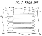
- the pressure generating chambers are large in aspect ratio, and walls 45 (Fig. 7) separating the pressure generating chambers from one another are thin, so that the bonding areas of the nozzle plate and the vibrating member are extremely small which are to be bonded to the flow passage forming substrate.
- a bonding region 41 on the side of the nozzle openings 40 is large, 800 ⁇ m x 141 ⁇ m, while bonding regions around ink supply inlets 43, which are formed on one side of the flow passage forming substrate which is opposite to the other side where the pressure generating chambers 42 are formed, are each small, 25 ⁇ m x 200 ⁇ m.
- the sum of those small bonding regions 44 around the ink supply inlets is also extremely small, about one-twentieth (1/20) of the bonding region 41 provided near the nozzle openings 40, and therefore it is difficult to obtain a sufficient adhesive strength on the side of the ink supply inlets.
- the conventional recording head is low in reliability.
- the present invention intends to overcome the above problems.
- the object is solved by the ink jet type recording head of independent claims 1 and 7. Further advantages, features, aspects and details of the invention are evident from the dependent claims, the description and the accompanying drawings.
- the claims are intended to be understood as a first non-limiting approach of defining the invention in general terms.
- an ink jet type recording head comprising: a nozzle plate which has a nozzle opening for jetting ink droplets; a flow passage forming substrate laminated on the nozzle plate and having a pressure generating chamber which is communicated with the nozzle opening, a common ink chamber for supplying ink to the pressure generating chambers and an ink supply inlet through which the ink chamber is communicated with the pressure generating chambers; a vibrating member laminated on the flow passage forming substrate; and a displacement effecting section for inflating and deflating the pressure generating chamber through the vibrating member; wherein the ink supply inlet in the flow passage forming substrates has a plurality of steps so that the ink supply inlet gradually expands towards the pressure generating chamber.
- bonding regions are obtained between the common ink chamber and the pressure generating chambers which are large in opening area, which provide a sufficiently high adhesive force which resists against a shearing stress produced by the displacement effecting means.
- Fig. 1 is a perspective view showing the structure of an ink jet type recording head.
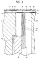
- Fig. 2 is a longitudinal sectional view showing the structure of a pressure generating chamber in the recording head according to a first embodiment of the present invention.
- the ink jet type recording head comprises two units, namely, a flow passage unit 1 and a displacement effecting unit 2.
- the flow passage unit comprises three elements; more specifically, it comprises: a nozzle plate 11; an ink flow passage forming substrate having pressure generating chambers 13, a common ink chamber 14, and ink supply inlets 15; and a vibrating member 17 which is made of a resin film, a SUS plate or the like.
- the flow passage forming substrate 16 has arrays of pressure generating chambers 13 which are arranged at equal intervals in correspondence to nozzle openings 12, 12, 12.... of the nozzle plate 11.
- the pressure generating chambers 13 are communicated through the respective ink supply inlets 15 to the common ink chamber 14.
- the nozzle plate 11, the flow passage forming substrate 16, and the vibrating member 17 are combined together, thus providing the flow passage unit 1. More specifically, the nozzle plate 11 is bonded liquid-tight to one side of the flow passage forming substrate 16 through an adhesive layer 26, while the vibrating member 17 is bonded liquid-tight to the other side of the flow passage forming substrate 16 through an adhesive layer 27.
- the displacement effecting unit 2 is designed as follows.
- the unit 2 includes arrays of displacement effecting sections 18 which are adapted to inflate and deflate the pressure generating chambers 13 to jet ink droplets.
- the displacement effecting sections 18 are arranged in arrays in the same direction as the pressure generating chambers 13 (in the direction of the arrow X in Fig. 1), and cantilevered to a base stand 19 in such a manner that their ends abuts against island-like protrusions 24 which are elastically deformed for inflating and deflating the pressure generating chambers 13.
- the displacement effecting sections 18 are each designed as follows. Its free end portion is an active section which comprises a piezo-electric layer 20 in which electrode layers 21 and 22 are alternately arranged.
- the electrodes 21 are drive electrodes provided respectively for the displacement effecting sections, and the electrodes 22 are parallel-connected to one another as common electrodes. Those electrodes 21 and 22 are connected through lead frames 23 to an external drive circuit (not shown).
- the above-described flow passage unit 1 and displacement effecting unit 2 are secured to a head frame 3 with an adhesive agent 25 in such a manner that the ends of the displacement effecting sections 18 abut on the island-like protrusions 24 formed on the vibrating member 17 in the regions which are confronted with the pressure generating chambers 13.
- the displacement effecting sections 18 inflate and deflate the pressure generating chambers 13 to jet ink droplets from the nozzle openings 12, and therefore a considerably great reaction force acts on the displacement generating unit 2.
- the adhesive agent 25 in order to bond the base stand 19 supporting the displacement effecting sections 18 to the head frame 3, the adhesive agent 25 must be great in the force of adhesion and less in fatigue.
- the adhesive agent of this type is low in cure rate at room temperature, thus lowering the work efficiency in the recording head assembling operation. In order to overcome this difficulty, the adhesive agent is heated to a degree of about 60°C to increase the cure rate.
- the head frame 3 is formed by injection molding macromolecular material, and the displacement effecting sections 18 are formed by using ceramics such as PZT (piezoelectric electrostriction element) showing piezoelectric characteristics.
- PZT pieoelectric electrostriction element
- the head frame 3 and the displacement effecting sections 18 are formed by using different materials, namely, macromolecular material and ceramics. Hence, at room temperature, the head frame 3 and the displacement effecting sections 18 are different in length because the room temperature is different from the temperature provided when the base stand 19 is bonded to the head frame, and those elements 3 and 18 are different in thermal expansion coefficient. This difference in length acts as a pressing force collectively near the pressure generating chambers 13 which abut on the ends of the displacement effecting sections 18. As a result, the flow passage forming substrate 16, the vibrating member 17, and the nozzle plate 11 are pushed upwardly, or deformed, as shown in Fig. 3. Because of this deformation, a load is applied to the flow passage forming substrate 16, the vibrating member 17, and the nozzle plate 11 to act, as a shearing force, on the adhesive agent layers 26 and 27 through which those components 16, 17 and 11 are combined together.
- Fig. 4 shows an embodiment of the flow passage forming substrate 16 which overcomes the above-described difficulty.
- reference character S designates a Silicon monocrystal wafer 200 to 300 ⁇ m in thickness which has a (110) crystal face.
- a plurality of pressure generating chambers 13, and a common ink chamber 14 are formed, and furthermore ink supply inlets are formed as through-holes. The wafer S thus processed is cut out to the size of the aimed ink jet type recording head.
- Fig. 5 shows the ink supply inlets 15 and the pressure generating chambers 13 of the flow passage forming substrate 16, and their relevant parts.
- the flow resistance of each of the ink supply inlets 15 should be substantially equal that of each of the nozzle openings 12 and much higher than that of each of the pressure generating chambers 13.
- each of the ink supply inlets 15 is much smaller in sectional area than each of the pressure generating chamber 13.
- the width w1 of the pressure generating chamber 13 is of the order of 100 ⁇ m
- the width w2 of the narrowest part 15a of the ink supply inlet 15, which substantially determines the flow resistance of the latter 15, is of the order of 25 ⁇ m.
- the common ink chamber 14 is shifted outwardly, and the distance L between each of the ink supply inlets 15 and the respective pressure generating chamber 13 is increased when compared with that in the conventional flow passage forming substrate. That is, in the embodiment, the distance is of the order of 600 ⁇ m which is three times that in the conventional flow passage forming substrate.
- the width of the ink supply inlet 15 is increased stepwise from the narrowest part 15a towards the pressure generating chamber 13.
- the ink supply inlet 15 includes three steps 15b, 15c and 15d being larger towards the pressure generating chamber, that is, the width of the ink supply inlet 15 is increased to 100 ⁇ m which is substantially equal to the width of the pressure generating chamber 13.
- reference numerals 28 and 29 designate small recesses or grooves formed in the adhesion regions. Those recesses or grooves absorb an excess of adhesive agent which is going to flow over the substrate during the substrate bonding operation; that is, they serve as adhesive agent absorbing means for preventing the adhesive agent from flowing into the pressure generating chamber and the ink supplying inlets.
- the bonding region having some width, 600 ⁇ m, is obtained without adversely affecting the function of the ink supply inlets 15.
- the length of the ink supply inlet region is larger as much as L2 than that L' (Fig. 7) of the conventional ink supply inlet, and therefore the bonding region is about twice as large as that in the conventional recording head.
- the temperature of the recording head was changed from a heating temperature of 60°C used for hardening the adhesive agent to a temperature of -30°C to which it may be cooled for instance during transportation by airplane, and the adhesive agent layers 26 and 27 of the flow passage forming board, the nozzle plate, and the vibrating member were inspected. However, none of the layers 26 and 27 were peeled off them.
- each of the ink supply outlets 15 are gradually larger from the ink chamber 14 towards the pressure generating chamber 13. That is, the width change between the ink supply outlets 15 and the pressure generating chamber 13 is relaxed as compared with that of the convnetional recording head.
- the ink is forcibly discharged by the application of a negative pressure to the nozzle openings 12, the formation of eddies in the boundary between the ink supply inlet and the pressure generating chamber is sufficiently suppressed, so that bubbles near the boundary can be also readily discharged from the nozzle opening 12.
- the above described embodiment is the recording head of the type that one end portion of each of the pressure generating chambers is communicated with the respective nozzle opening, and the ink is supplied from one side of the pressure generating chamber.
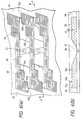
- the invention is not limited thereto or thereby. That is, the recording head may be modified as shown in Figs. 6(a) and 6(b).
- This is a second embodiment of the invention.
- a nozzle opening 31 is located at the center of each of the pressure generating chambers 30; and ink supply inlets 32 and 33, and common ink chambers 34 and 35 are provided on both sides of the pressure generating chambers 30, so that the recording head is improved in ink supplying performance; that is, it is operated at high speed.
- the second embodiment is more noticeable in effect than the first embodiment.
- the bonding regions around the pressure generating chambers 30 are very small.
- this problem is solved as follows.
- the narrowest parts 32a and 33a are provided on the sides of the common ink chambers, and are communicated through long passageways including a plurality of steps 32b, 32c, 33b and 33c with the pressure generating chamber 30.
- the bonding region can be increased, that is, the adhesive strength can be increased.
- both ends of the pressure generating chambers receive equally the load applied thereto. This feature illuminates the difficulty that the adhesive agent layers peel off the flow passage forming unit at a particular point or points.
- the flow resistance of each of the ink supply inlets must be higher than in the case where each pressure generating chamber has only one ink supply inlet.
- the narrowest parts are decreased in width to increase the flow resistance, then it is difficult to make the dimensions of the ink supply inlets high in accuracy. Therefore, in this case, it is preferable that the depth d of the ink supply inlets is made smaller by half-etching.
- an ink jet type recording head comprises: a nozzle plate which has a nozzle opening for jetting ink droplets; a flow passage forming substrate laminated on the nozzle plate and having a pressure generating chamber which is communicated with the nozzle opening, a common ink chamber for supplying ink to the pressure generating chambers and an ink supply inlet through which the ink chamber are communicated with the pressure generating chambers; a vibrating member laminated on the flow passage forming substrate; and a displacement effecting section for inflating and deflating the pressure generating chamber through the vibrating member; wherein the ink supply inlet in the flow passage forming substrates has a plurality of steps so that the ink supply inlet gradually expands towards the pressure generating chamber.
- bonding areas can be obtained between the common ink chamber and the pressure generating chambers which are large in opening area, which provides an adhesive force which resists against the shearing force produced by the displacement effecting means.
Abstract
Description
- This invention relates to an ink jet type recording head of on-demand system which jets ink droplets in response to printing signals to form dots on a recording medium.
- An ink jet type recording head comprises a flow passage unit and a displacement effecting unit. The flow passage unit comprises: a nozzle plate having nozzle openings; a flow passage forming substrate having pressure generating chambers which are communicated with nozzle openings, a common ink chamber and ink supply inlets; and a vibrating member which sealingly covers the flow passage forming substrate, and inflates and deflates the pressure generating chambers, being externally displaced. The displacement effecting unit is adapted to apply mechanical energy to the pressure generating chambers through the vibrating member to jet ink.
- In the ink jet type recording head, each of the ink supply inlets greatly affect the picture quality of the resultant print as well as each of the nozzle openings, and is an important element which changes the flow passage impedance ratio of the ink supply inlet and the nozzle opening, and the absolute value of the flow passage impedance. Hence, the dimensions and the flow resistances of the ink supply inlet and the nozzle opening greatly affect various characteristics of the recording head such as an ink-droplet jetting speed, a quantity of ink droplet, and an ink-droplet jetting frequency.
- This problem may be solved by a technique which has been disclosed, for instance, by Japanese Patent Application No. Hei. 5-229114. That is, by anisotropic-etching a silicon monocrystal wafer, the pressure generating chambers, the common ink chamber, and the ink supply inlets can be formed with high dimensional accuracy.
- On the other hand, in a recording head for high-density print, the pressure generating chambers are large in aspect ratio, and walls 45 (Fig. 7) separating the pressure generating chambers from one another are thin, so that the bonding areas of the nozzle plate and the vibrating member are extremely small which are to be bonded to the flow passage forming substrate.
- In an example of the conventional recording head described above, as shown in Fig. 7, a
bonding region 41 on the side of thenozzle openings 40 is large, 800 µm x 141 µm, while bonding regions aroundink supply inlets 43, which are formed on one side of the flow passage forming substrate which is opposite to the other side where thepressure generating chambers 42 are formed, are each small, 25 µm x 200 µm. The sum of thosesmall bonding regions 44 around the ink supply inlets is also extremely small, about one-twentieth (1/20) of thebonding region 41 provided near thenozzle openings 40, and therefore it is difficult to obtain a sufficient adhesive strength on the side of the ink supply inlets. - Accordingly, at the junctions of the flow passage forming substrate, the nozzle plate and the vibrating member which form the ink flow paths, those components may be separated from one another for instance because of the non-uniform application of the adhesive agent; and the ink may leak from the pressure generating chambers into one another. Thus, the conventional recording head is low in reliability.
- The present invention intends to overcome the above problems. The object is solved by the ink jet type recording head of
independent claims 1 and 7. Further advantages, features, aspects and details of the invention are evident from the dependent claims, the description and the accompanying drawings. The claims are intended to be understood as a first non-limiting approach of defining the invention in general terms. - It is an aspect of the invention to provide an ink jet type recording head in which, while the ink supply inlets are controlled in flow resistance, the nozzle plate, the flow passage forming substrate, and the vibrating member are bonded together with a sufficiently high adhesive strength.
- According to the invention, an ink jet type recording head is provided comprising: a nozzle plate which has a nozzle opening for jetting ink droplets; a flow passage forming substrate laminated on the nozzle plate and having a pressure generating chamber which is communicated with the nozzle opening, a common ink chamber for supplying ink to the pressure generating chambers and an ink supply inlet through which the ink chamber is communicated with the pressure generating chambers; a vibrating member laminated on the flow passage forming substrate; and a displacement effecting section for inflating and deflating the pressure generating chamber through the vibrating member; wherein the ink supply inlet in the flow passage forming substrates has a plurality of steps so that the ink supply inlet gradually expands towards the pressure generating chamber.
- With the recording head, bonding regions are obtained between the common ink chamber and the pressure generating chambers which are large in opening area, which provide a sufficiently high adhesive force which resists against a shearing stress produced by the displacement effecting means.
- The invention will be better understood by reference to the following description of embodiments of the invention taken in conjunction with the accompanying drawings, wherein
- Fig. 1 is an exploded perspective view showing an ink jet type recording head;
- Fig. 2 is a sectional view of part of a recording head according to a first embodiment of the present invention;
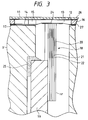
- Fig. 3 is a sectional view showing a state of the recording head at room temperature which has been heated so as to join a head frame and a displacement effecting unit together;
- Fig. 4 is a front view showing the first embodiment of a flow passage forming substrate which is formed by cutting a silicon monocrystal wafer;
- Fig. 5 is an enlarged diagram of the flow passage forming substrate, mainly showing pressure generating chambers and parts concerning the latter;
- Fig. 6(a) is an enlarged diagram of a second embodiment of the flow passage forming substrate, mainly showing pressure generating chambers and parts concerning the latter, and Fig. 6(b) is a sectional diagram taken along line A-A in Fig. 6(a); and
- Fig. 7 is an enlarged front view of an example of a flow passage forming substrate in a conventional ink jet type recording head, mainly showing pressure generating chambers and parts concerning the latter.
- Fig. 1 is a perspective view showing the structure of an ink jet type recording head. Fig. 2 is a longitudinal sectional view showing the structure of a pressure generating chamber in the recording head according to a first embodiment of the present invention. Fundamentally, the ink jet type recording head comprises two units, namely, a
flow passage unit 1 and adisplacement effecting unit 2. The flow passage unit comprises three elements; more specifically, it comprises: anozzle plate 11; an ink flow passage forming substrate havingpressure generating chambers 13, acommon ink chamber 14, andink supply inlets 15; and a vibratingmember 17 which is made of a resin film, a SUS plate or the like. - The flow
passage forming substrate 16 has arrays ofpressure generating chambers 13 which are arranged at equal intervals in correspondence tonozzle openings nozzle plate 11. Thepressure generating chambers 13 are communicated through the respectiveink supply inlets 15 to thecommon ink chamber 14. - The
nozzle plate 11, the flowpassage forming substrate 16, and the vibratingmember 17 are combined together, thus providing theflow passage unit 1. More specifically, thenozzle plate 11 is bonded liquid-tight to one side of the flowpassage forming substrate 16 through anadhesive layer 26, while the vibratingmember 17 is bonded liquid-tight to the other side of the flowpassage forming substrate 16 through anadhesive layer 27. - On the other hand, the
displacement effecting unit 2 is designed as follows. Theunit 2 includes arrays ofdisplacement effecting sections 18 which are adapted to inflate and deflate thepressure generating chambers 13 to jet ink droplets. Thedisplacement effecting sections 18 are arranged in arrays in the same direction as the pressure generating chambers 13 (in the direction of the arrow X in Fig. 1), and cantilevered to abase stand 19 in such a manner that their ends abuts against island-like protrusions 24 which are elastically deformed for inflating and deflating thepressure generating chambers 13. - The
displacement effecting sections 18 are each designed as follows. Its free end portion is an active section which comprises a piezo-electric layer 20 in whichelectrode layers electrodes 21 are drive electrodes provided respectively for the displacement effecting sections, and theelectrodes 22 are parallel-connected to one another as common electrodes. Thoseelectrodes lead frames 23 to an external drive circuit (not shown). - The above-described
flow passage unit 1 anddisplacement effecting unit 2 are secured to ahead frame 3 with anadhesive agent 25 in such a manner that the ends of thedisplacement effecting sections 18 abut on the island-like protrusions 24 formed on the vibratingmember 17 in the regions which are confronted with thepressure generating chambers 13. - During printing, the
displacement effecting sections 18 inflate and deflate thepressure generating chambers 13 to jet ink droplets from thenozzle openings 12, and therefore a considerably great reaction force acts on thedisplacement generating unit 2. Hence, in order to bond thebase stand 19 supporting thedisplacement effecting sections 18 to thehead frame 3, theadhesive agent 25 must be great in the force of adhesion and less in fatigue. The adhesive agent of this type is low in cure rate at room temperature, thus lowering the work efficiency in the recording head assembling operation. In order to overcome this difficulty, the adhesive agent is heated to a degree of about 60°C to increase the cure rate. - On the other hand, for convenience in manufacture, the
head frame 3 is formed by injection molding macromolecular material, and thedisplacement effecting sections 18 are formed by using ceramics such as PZT (piezoelectric electrostriction element) showing piezoelectric characteristics. - As described above, the
head frame 3 and thedisplacement effecting sections 18 are formed by using different materials, namely, macromolecular material and ceramics. Hence, at room temperature, thehead frame 3 and thedisplacement effecting sections 18 are different in length because the room temperature is different from the temperature provided when thebase stand 19 is bonded to the head frame, and thoseelements pressure generating chambers 13 which abut on the ends of thedisplacement effecting sections 18. As a result, the flowpassage forming substrate 16, the vibratingmember 17, and thenozzle plate 11 are pushed upwardly, or deformed, as shown in Fig. 3. Because of this deformation, a load is applied to the flowpassage forming substrate 16, the vibratingmember 17, and thenozzle plate 11 to act, as a shearing force, on theadhesive agent layers components - Fig. 4 shows an embodiment of the flow
passage forming substrate 16 which overcomes the above-described difficulty. In Fig. 4, reference character S designates a Silicon monocrystal wafer 200 to 300 µm in thickness which has a (110) crystal face. In the wafer S, a plurality ofpressure generating chambers 13, and acommon ink chamber 14 are formed, and furthermore ink supply inlets are formed as through-holes. The wafer S thus processed is cut out to the size of the aimed ink jet type recording head. - Fig. 5 shows the
ink supply inlets 15 and thepressure generating chambers 13 of the flowpassage forming substrate 16, and their relevant parts. In the recording head, the flow resistance of each of theink supply inlets 15 should be substantially equal that of each of thenozzle openings 12 and much higher than that of each of thepressure generating chambers 13. Hence, each of theink supply inlets 15 is much smaller in sectional area than each of thepressure generating chamber 13. - That is, in a concrete embodiment of the flow passage forming substrate, the width w1 of the
pressure generating chamber 13 is of the order of 100 µm, and the width w2 of thenarrowest part 15a of theink supply inlet 15, which substantially determines the flow resistance of the latter 15, is of the order of 25 µm. - In addition, the
common ink chamber 14 is shifted outwardly, and the distance L between each of theink supply inlets 15 and the respectivepressure generating chamber 13 is increased when compared with that in the conventional flow passage forming substrate. That is, in the embodiment, the distance is of the order of 600 µm which is three times that in the conventional flow passage forming substrate. The width of theink supply inlet 15 is increased stepwise from thenarrowest part 15a towards thepressure generating chamber 13. In the example, theink supply inlet 15 includes threesteps ink supply inlet 15 is increased to 100 µm which is substantially equal to the width of thepressure generating chamber 13. - In Fig. 5,
reference numerals - Thus, between the
common ink chamber 14 which, in the flowpassage forming substrate 16, is largest in opening area and thepressure generating chambers 13 which are ranked next to thecommon ink chamber 14 in opening area, a bonding region having some width, 600 µm, is obtained without adversely affecting the function of theink supply inlets 15. In the recording head of the invention, the length of the ink supply inlet region is larger as much as L2 than that L' (Fig. 7) of the conventional ink supply inlet, and therefore the bonding region is about twice as large as that in the conventional recording head. - In order to confirm the effects of the above described increase in bonding region, the temperature of the recording head was changed from a heating temperature of 60°C used for hardening the adhesive agent to a temperature of -30°C to which it may be cooled for instance during transportation by airplane, and the adhesive agent layers 26 and 27 of the flow passage forming board, the nozzle plate, and the vibrating member were inspected. However, none of the
layers - The width of each of the
ink supply outlets 15 are gradually larger from theink chamber 14 towards thepressure generating chamber 13. That is, the width change between theink supply outlets 15 and thepressure generating chamber 13 is relaxed as compared with that of the convnetional recording head. Hence, in the case where, in order to regain the ink jetting performance, the ink is forcibly discharged by the application of a negative pressure to thenozzle openings 12, the formation of eddies in the boundary between the ink supply inlet and the pressure generating chamber is sufficiently suppressed, so that bubbles near the boundary can be also readily discharged from thenozzle opening 12. - The above described embodiment is the recording head of the type that one end portion of each of the pressure generating chambers is communicated with the respective nozzle opening, and the ink is supplied from one side of the pressure generating chamber. However, the invention is not limited thereto or thereby. That is, the recording head may be modified as shown in Figs. 6(a) and 6(b). This is a second embodiment of the invention. In the second embodiment, a
nozzle opening 31 is located at the center of each of thepressure generating chambers 30; andink supply inlets common ink chambers pressure generating chambers 30, so that the recording head is improved in ink supplying performance; that is, it is operated at high speed. Thus, the second embodiment is more noticeable in effect than the first embodiment. - More specifically, in the case where the two
common ink chambers pressure generating chambers 30, the bonding regions around thepressure generating chambers 30 are very small. However, in the second embodiment, this problem is solved as follows. In each of the ink supply inlets, thenarrowest parts steps pressure generating chamber 30. Hence, in the second embodiment, while theink supply inlets - In the case where the
ink supply inlets pressure generating chambers 30, the flow resistance of each of the ink supply inlets must be higher than in the case where each pressure generating chamber has only one ink supply inlet. However, if the narrowest parts are decreased in width to increase the flow resistance, then it is difficult to make the dimensions of the ink supply inlets high in accuracy. Therefore, in this case, it is preferable that the depth d of the ink supply inlets is made smaller by half-etching. - As described above, an ink jet type recording head according to the present invention comprises: a nozzle plate which has a nozzle opening for jetting ink droplets; a flow passage forming substrate laminated on the nozzle plate and having a pressure generating chamber which is communicated with the nozzle opening, a common ink chamber for supplying ink to the pressure generating chambers and an ink supply inlet through which the ink chamber are communicated with the pressure generating chambers; a vibrating member laminated on the flow passage forming substrate; and a displacement effecting section for inflating and deflating the pressure generating chamber through the vibrating member; wherein the ink supply inlet in the flow passage forming substrates has a plurality of steps so that the ink supply inlet gradually expands towards the pressure generating chamber.
- Hence, bonding areas can be obtained between the common ink chamber and the pressure generating chambers which are large in opening area, which provides an adhesive force which resists against the shearing force produced by the displacement effecting means.
Claims (8)
- An ink jet type recording head comprising:a nozzle plate (11) having nozzle openings (12;31) for jetting ink droplets;a flow passage forming substrate (16) laminated on said nozzle plate (11) and having at least one pressure generating chamber (13;30) which is communicated with said nozzle openings (12;31), a common ink chamber (14;34,35) for supplying ink to said at least one pressure generating chamber (13;30) and an ink supply inlet (15;32,33) through which said ink chamber (14;34,35) is communicated with said at least one pressure generating chamber (13;30);a vibrating member (17) laminated on said flow passage forming substrate (16); anda displacement effecting section (18) for inflating and deflating said pressure generating chamber (13;30) through said vibrating member (17);wherein said ink supply inlet (15;32,33) in said flow passage forming substrate (16) has a plurality of steps (15a,15b,15c,15d;32a,32b,32c;33a,33b,33c) so that said ink supply inlet (15;32,33) gradually expands towards said pressure generating chamber (13;30).
- The ink jet type recording head according to claim 1, wherein said pressure generating chamber (13) has a first and a second end, said first end of said pressure generating chamber (13) is communicated with said nozzle opening (12) and said second end of said pressure generating chamber (13) is communicated through said ink supply inlet (15) to said common ink chamber (14).
- The ink jet type recording head according to claim 1, wherein said pressure generating chamber (30) is communicated with said nozzle opening (31) at the center thereof, and both sides of said pressure generating chamber (30) are communicated with two common ink chambers (34,35) through said ink supply inlets (32,33).
- The ink jet type recording head according to one of the preceding claims, wherein said flow passage forming substrate (16) is made of a silicon monocrystal wafer (s) and said pressure generating chamber (13;30), said common ink chamber (14) and said ink supply inlet (15;32,33) are formed by anisotropic-etching said silicon monocrystal wafer.
- The ink jet type recording head according to one of the preceding claims, wherein said nozzle plate (11), said flow passage forming substrate (16), said vibrating member (17) are bonded by adhesive, and recesses (28,29) for absorbing excess of said adhesive are formed in adhesion regions of said flow passage forming substrate (16).
- The ink jet type recording head according to one of the preceding claims, wherein said vibrating member (17) has an elastic deformation portion which is elastically deformed for inflating and deflating said pressure generating chamber (13;30), and an end of said displacement effecting section (18) abuts against said elastic deformation portion.
- An ink jet type recording head especially according to one of the preceding claims, comprising:means for pressurizing ink to jet ink droplets from a nozzle opening;means for supplying the ink to the pressurizing means; andmeans for guiding the ink from the supplying means to the pressurizing means;wherein the guiding means gradually expands from the supplying means towards the pressurizing means.
- The ink jet type recording head according to claim 7, wherein the guiding means includes a plurality of steps so that the guiding means gradually expands towards the pressurizing means.
Applications Claiming Priority (6)
| Application Number | Priority Date | Filing Date | Title |
|---|---|---|---|
| JP14495595 | 1995-06-12 | ||
| JP14495595 | 1995-06-12 | ||
| JP144955/95 | 1995-06-12 | ||
| JP15169496A JP3679863B2 (en) | 1995-06-12 | 1996-05-23 | Inkjet recording head |
| JP15169496 | 1996-05-23 | ||
| JP151694/96 | 1996-05-23 |
Publications (3)
| Publication Number | Publication Date |
|---|---|
| EP0748690A2 true EP0748690A2 (en) | 1996-12-18 |
| EP0748690A3 EP0748690A3 (en) | 1998-01-28 |
| EP0748690B1 EP0748690B1 (en) | 2001-11-07 |
Family
ID=26476227
Family Applications (1)
| Application Number | Title | Priority Date | Filing Date |
|---|---|---|---|
| EP96109431A Expired - Lifetime EP0748690B1 (en) | 1995-06-12 | 1996-06-12 | Ink jet type recording head |
Country Status (4)
| Country | Link |
|---|---|
| US (1) | US5896149A (en) |
| EP (1) | EP0748690B1 (en) |
| JP (1) | JP3679863B2 (en) |
| DE (1) | DE69616656T2 (en) |
Cited By (3)
| Publication number | Priority date | Publication date | Assignee | Title |
|---|---|---|---|---|
| EP0761447A2 (en) * | 1995-09-05 | 1997-03-12 | Seiko Epson Corporation | Ink jet recording head and method of producing the same |
| EP0931650A1 (en) * | 1997-06-17 | 1999-07-28 | Seiko Epson Corporation | Ink jet recording head |
| US6729002B1 (en) | 1995-09-05 | 2004-05-04 | Seiko Epson Corporation | Method of producing an ink jet recording head |
Families Citing this family (11)
| Publication number | Priority date | Publication date | Assignee | Title |
|---|---|---|---|---|
| JPH10202921A (en) * | 1997-01-22 | 1998-08-04 | Minolta Co Ltd | Ink jet recording head |
| JPH115303A (en) * | 1997-06-18 | 1999-01-12 | Brother Ind Ltd | Ink jet printer head |
| DE69804724T2 (en) * | 1997-07-25 | 2002-08-14 | Seiko Epson Corp | Inkjet printhead and its manufacturing process |
| JP3436299B2 (en) * | 1998-08-21 | 2003-08-11 | セイコーエプソン株式会社 | Ink jet recording head |
| JP4570178B2 (en) * | 1998-11-26 | 2010-10-27 | 富士フイルム株式会社 | Ink jet head, manufacturing method thereof, and printing apparatus |
| US6444593B1 (en) | 1998-12-02 | 2002-09-03 | Advanced Micro Devices, Inc. | Surface treatment of low-K SiOF to prevent metal interaction |
| US6252303B1 (en) * | 1998-12-02 | 2001-06-26 | Advanced Micro Devices, Inc. | Intergration of low-K SiOF as inter-layer dielectric |
| JP4269136B2 (en) * | 1999-12-10 | 2009-05-27 | 富士フイルム株式会社 | Ink jet head, method for manufacturing ink jet head, and printing apparatus |
| JP4349282B2 (en) * | 2002-07-09 | 2009-10-21 | セイコーエプソン株式会社 | Fine forging method and liquid jet head manufacturing method |
| CN100478173C (en) * | 2003-05-06 | 2009-04-15 | 精工爱普生株式会社 | Fluid jetting head and fluid jetting device |
| US7341330B2 (en) * | 2005-02-28 | 2008-03-11 | Silverbrook Research Pty Ltd | Substrates adapted for adhesive bonding |
Citations (6)
| Publication number | Priority date | Publication date | Assignee | Title |
|---|---|---|---|---|
| JPS59179357A (en) * | 1983-03-31 | 1984-10-11 | Fujitsu Ltd | Ink jet recording apparatus |
| JPS62135378A (en) * | 1985-12-09 | 1987-06-18 | Nec Corp | Ink jet printing head |
| DE9011816U1 (en) * | 1990-08-14 | 1990-10-18 | Siemens Ag, 8000 Muenchen, De | |
| EP0573055A2 (en) * | 1992-06-05 | 1993-12-08 | Seiko Epson Corporation | Ink jet recording head |
| EP0600382A2 (en) * | 1992-11-25 | 1994-06-08 | Seiko Epson Corporation | Ink-jet type recording head |
| EP0616891A1 (en) * | 1993-03-01 | 1994-09-28 | Seiko Epson Corporation | Ink jet recording apparatus and method of controlling same |
Family Cites Families (6)
| Publication number | Priority date | Publication date | Assignee | Title |
|---|---|---|---|---|
| JPS60139457A (en) * | 1983-12-27 | 1985-07-24 | Fujitsu Ltd | Ink jet print head |
| JP3079688B2 (en) * | 1991-10-15 | 2000-08-21 | 富士通株式会社 | Ink jet head and method of manufacturing the same |
| JP3255178B2 (en) * | 1991-12-26 | 2002-02-12 | セイコーエプソン株式会社 | Inkjet head |
| JP2932877B2 (en) * | 1992-02-06 | 1999-08-09 | セイコーエプソン株式会社 | Method of manufacturing inkjet head |
| JP3218664B2 (en) * | 1992-02-19 | 2001-10-15 | セイコーエプソン株式会社 | Inkjet print head |
| JP3147132B2 (en) * | 1992-03-03 | 2001-03-19 | セイコーエプソン株式会社 | Inkjet recording head, diaphragm for inkjet recording head, and method of manufacturing diaphragm for inkjet recording head |
-
1996
- 1996-05-23 JP JP15169496A patent/JP3679863B2/en not_active Expired - Fee Related
- 1996-06-11 US US08/660,578 patent/US5896149A/en not_active Expired - Lifetime
- 1996-06-12 EP EP96109431A patent/EP0748690B1/en not_active Expired - Lifetime
- 1996-06-12 DE DE69616656T patent/DE69616656T2/en not_active Expired - Lifetime
Patent Citations (6)
| Publication number | Priority date | Publication date | Assignee | Title |
|---|---|---|---|---|
| JPS59179357A (en) * | 1983-03-31 | 1984-10-11 | Fujitsu Ltd | Ink jet recording apparatus |
| JPS62135378A (en) * | 1985-12-09 | 1987-06-18 | Nec Corp | Ink jet printing head |
| DE9011816U1 (en) * | 1990-08-14 | 1990-10-18 | Siemens Ag, 8000 Muenchen, De | |
| EP0573055A2 (en) * | 1992-06-05 | 1993-12-08 | Seiko Epson Corporation | Ink jet recording head |
| EP0600382A2 (en) * | 1992-11-25 | 1994-06-08 | Seiko Epson Corporation | Ink-jet type recording head |
| EP0616891A1 (en) * | 1993-03-01 | 1994-09-28 | Seiko Epson Corporation | Ink jet recording apparatus and method of controlling same |
Non-Patent Citations (2)
| Title |
|---|
| PATENT ABSTRACTS OF JAPAN vol. 009, no. 038 (M-358), 19 February 1985 & JP 59 179357 A (FUJITSU KK), 11 October 1984, * |
| PATENT ABSTRACTS OF JAPAN vol. 011, no. 356 (M-644), 20 November 1987 & JP 62 135378 A (NEC CORP), 18 June 1987, * |
Cited By (11)
| Publication number | Priority date | Publication date | Assignee | Title |
|---|---|---|---|---|
| EP0761447A2 (en) * | 1995-09-05 | 1997-03-12 | Seiko Epson Corporation | Ink jet recording head and method of producing the same |
| EP0761447A3 (en) * | 1995-09-05 | 1998-11-25 | Seiko Epson Corporation | Ink jet recording head and method of producing the same |
| US6139132A (en) * | 1995-09-05 | 2000-10-31 | Seiko Epson Corporation | Ink jet recording head with nozzle communicating hole having smaller width than pressurizing chambers in direction of array of pressurizing chambers |
| EP1104698A3 (en) * | 1995-09-05 | 2002-01-09 | Seiko Epson Corporation | Ink jet recording head and method of producing the same |
| US6460981B1 (en) | 1995-09-05 | 2002-10-08 | Seiko Epson Corp | Ink jet recording head having spacer with etched pressurizing chambers and ink supply ports |
| US6561633B2 (en) | 1995-09-05 | 2003-05-13 | Seiko Epson Corporation | Ink jet recording head having spacer with etched pressurizing chambers and ink supply ports |
| US6729002B1 (en) | 1995-09-05 | 2004-05-04 | Seiko Epson Corporation | Method of producing an ink jet recording head |
| US7028377B2 (en) | 1995-09-05 | 2006-04-18 | Seiko Epson Corporation | Method of producing an ink jet recording head |
| EP0931650A1 (en) * | 1997-06-17 | 1999-07-28 | Seiko Epson Corporation | Ink jet recording head |
| EP0931650A4 (en) * | 1997-06-17 | 2000-08-23 | Seiko Epson Corp | Ink jet recording head |
| EP2221180A1 (en) * | 1997-06-17 | 2010-08-25 | Seiko Epson Corporation | Ink jet recording head |
Also Published As
| Publication number | Publication date |
|---|---|
| JP3679863B2 (en) | 2005-08-03 |
| DE69616656D1 (en) | 2001-12-13 |
| DE69616656T2 (en) | 2002-05-02 |
| JPH0957961A (en) | 1997-03-04 |
| EP0748690B1 (en) | 2001-11-07 |
| US5896149A (en) | 1999-04-20 |
| EP0748690A3 (en) | 1998-01-28 |
Similar Documents
| Publication | Publication Date | Title |
|---|---|---|
| EP0748690B1 (en) | Ink jet type recording head | |
| US5359354A (en) | Ink jet head with dummy slots | |
| US7946682B2 (en) | Plate member for a liquid jet head | |
| EP1170127B1 (en) | Ink jet recording head | |
| CA2648226A1 (en) | Droplet deposition apparatus | |
| JPH10264390A (en) | Ink-jet printer head | |
| EP0867287B1 (en) | Ink jet recording head | |
| JPH10157108A (en) | Ink jet printer head | |
| JP3244946B2 (en) | Inkjet head | |
| US6874869B1 (en) | Inkjet printhead | |
| EP1022140B1 (en) | Inkjet printhead | |
| JP3491193B2 (en) | Ink jet recording head and ink jet recording apparatus | |
| JP2003039669A (en) | Ink jet recording head | |
| JP2001030483A (en) | Ink jet head | |
| JPH09123466A (en) | Manufacture of ink jet printer head | |
| JPH10202888A (en) | Ink jet printing head | |
| JPH0948133A (en) | Manufacture of ink jet printer head | |
| JPH06106724A (en) | Ink-jet head | |
| JPH06143563A (en) | Ink jet head | |
| JPH0373348A (en) | Ink-jet recording device | |
| JPH09239994A (en) | Bonding of nozzle plate | |
| JPH1158749A (en) | Production method of ink-jet head | |
| JPH11300953A (en) | Ink jet head | |
| JP2003062998A (en) | Ink-jet recording head and ink-jet recording apparatus | |
| JPH07304169A (en) | Droplet jet device |
Legal Events
| Date | Code | Title | Description |
|---|---|---|---|
| PUAI | Public reference made under article 153(3) epc to a published international application that has entered the european phase |
Free format text: ORIGINAL CODE: 0009012 |
|
| AK | Designated contracting states |
Kind code of ref document: A2 Designated state(s): DE FR GB IT |
|
| PUAL | Search report despatched |
Free format text: ORIGINAL CODE: 0009013 |
|
| RHK1 | Main classification (correction) |
Ipc: B41J 2/14 |
|
| AK | Designated contracting states |
Kind code of ref document: A3 Designated state(s): DE FR GB IT |
|
| 17P | Request for examination filed |
Effective date: 19980406 |
|
| 17Q | First examination report despatched |
Effective date: 19990317 |
|
| GRAG | Despatch of communication of intention to grant |
Free format text: ORIGINAL CODE: EPIDOS AGRA |
|
| GRAG | Despatch of communication of intention to grant |
Free format text: ORIGINAL CODE: EPIDOS AGRA |
|
| GRAH | Despatch of communication of intention to grant a patent |
Free format text: ORIGINAL CODE: EPIDOS IGRA |
|
| GRAH | Despatch of communication of intention to grant a patent |
Free format text: ORIGINAL CODE: EPIDOS IGRA |
|
| GRAA | (expected) grant |
Free format text: ORIGINAL CODE: 0009210 |
|
| AK | Designated contracting states |
Kind code of ref document: B1 Designated state(s): DE FR GB IT |
|
| REF | Corresponds to: |
Ref document number: 69616656 Country of ref document: DE Date of ref document: 20011213 |
|
| REG | Reference to a national code |
Ref country code: GB Ref legal event code: IF02 |
|
| ET | Fr: translation filed | ||
| PLBE | No opposition filed within time limit |
Free format text: ORIGINAL CODE: 0009261 |
|
| STAA | Information on the status of an ep patent application or granted ep patent |
Free format text: STATUS: NO OPPOSITION FILED WITHIN TIME LIMIT |
|
| 26N | No opposition filed | ||
| PGFP | Annual fee paid to national office [announced via postgrant information from national office to epo] |
Ref country code: DE Payment date: 20120607 Year of fee payment: 17 |
|
| PGFP | Annual fee paid to national office [announced via postgrant information from national office to epo] |
Ref country code: FR Payment date: 20120619 Year of fee payment: 17 Ref country code: GB Payment date: 20120606 Year of fee payment: 17 |
|
| PGFP | Annual fee paid to national office [announced via postgrant information from national office to epo] |
Ref country code: IT Payment date: 20120613 Year of fee payment: 17 |
|
| GBPC | Gb: european patent ceased through non-payment of renewal fee |
Effective date: 20130612 |
|
| REG | Reference to a national code |
Ref country code: DE Ref legal event code: R119 Ref document number: 69616656 Country of ref document: DE Effective date: 20140101 |
|
| REG | Reference to a national code |
Ref country code: FR Ref legal event code: ST Effective date: 20140228 |
|
| PG25 | Lapsed in a contracting state [announced via postgrant information from national office to epo] |
Ref country code: DE Free format text: LAPSE BECAUSE OF NON-PAYMENT OF DUE FEES Effective date: 20140101 Ref country code: GB Free format text: LAPSE BECAUSE OF NON-PAYMENT OF DUE FEES Effective date: 20130612 |
|
| PG25 | Lapsed in a contracting state [announced via postgrant information from national office to epo] |
Ref country code: FR Free format text: LAPSE BECAUSE OF NON-PAYMENT OF DUE FEES Effective date: 20130701 Ref country code: IT Free format text: LAPSE BECAUSE OF NON-PAYMENT OF DUE FEES Effective date: 20130612 |