EP0748915A2 - Door or similar with electrical drive unit - Google Patents
Door or similar with electrical drive unit Download PDFInfo
- Publication number
- EP0748915A2 EP0748915A2 EP96109521A EP96109521A EP0748915A2 EP 0748915 A2 EP0748915 A2 EP 0748915A2 EP 96109521 A EP96109521 A EP 96109521A EP 96109521 A EP96109521 A EP 96109521A EP 0748915 A2 EP0748915 A2 EP 0748915A2
- Authority
- EP
- European Patent Office
- Prior art keywords
- door leaf
- drive unit
- gate according
- motor
- commutator
- Prior art date
- Legal status (The legal status is an assumption and is not a legal conclusion. Google has not performed a legal analysis and makes no representation as to the accuracy of the status listed.)
- Granted
Links
Images
Classifications
-
- E—FIXED CONSTRUCTIONS
- E05—LOCKS; KEYS; WINDOW OR DOOR FITTINGS; SAFES
- E05F—DEVICES FOR MOVING WINGS INTO OPEN OR CLOSED POSITION; CHECKS FOR WINGS; WING FITTINGS NOT OTHERWISE PROVIDED FOR, CONCERNED WITH THE FUNCTIONING OF THE WING
- E05F15/00—Power-operated mechanisms for wings
- E05F15/60—Power-operated mechanisms for wings using electrical actuators
- E05F15/603—Power-operated mechanisms for wings using electrical actuators using rotary electromotors
-
- E—FIXED CONSTRUCTIONS
- E05—LOCKS; KEYS; WINDOW OR DOOR FITTINGS; SAFES
- E05Y—INDEXING SCHEME RELATING TO HINGES OR OTHER SUSPENSION DEVICES FOR DOORS, WINDOWS OR WINGS AND DEVICES FOR MOVING WINGS INTO OPEN OR CLOSED POSITION, CHECKS FOR WINGS AND WING FITTINGS NOT OTHERWISE PROVIDED FOR, CONCERNED WITH THE FUNCTIONING OF THE WING
- E05Y2900/00—Application of doors, windows, wings or fittings thereof
- E05Y2900/10—Application of doors, windows, wings or fittings thereof for buildings or parts thereof
- E05Y2900/13—Application of doors, windows, wings or fittings thereof for buildings or parts thereof characterised by the type of wing
- E05Y2900/132—Doors
Definitions
- the invention relates to a gate or the like closing device with a single or multi-part door leaf which can be moved between the closed and open positions by means of an electric direct current motor drive unit, to which the output shaft of the drive unit is connected in a gearbox and whose movement distance is reproduced proportionally by a pulse sequence which is generated by the Rotational movement of a shaft of the drive unit is derived and which is fed to a counting device in an evaluation circuit, the counter values are compared with stored values for predetermined or previously entered door leaf positions and are evaluated in the event of coincidence with control signals for the drive unit.
- the gates or the like mentioned here are to be understood in addition to actual gates of all types as building or site closure also doors, windows, shutters, awnings and so on, which are accessible to a motorized operation.
- the movement path has already been simulated by means of a pulse train with the success that the control of the drive for the deduction of the door leaf movement in the end positions by counting the movement path-dependent pulse train and comparing it with stored values marking the end positions can be accommodated in the smallest space, for example in the same housing as the drive motor.
- the stored values can be determined after installing the door by moving the door leaf using manual control or low drive speed - creep speed - according to the actual conditions, using the pulse sequence given.
- the number of revolutions of this and other shafts of the drive unit is a correspondingly accurate representation of the movement distance of the door leaf.
- the pulse sequence or number of pulses corresponding to the movement distance is therefore generated by a converter which is arranged on one of the shafts of the drive unit.
- This can be a radially slotted disk, on the slot arrangement of which a light barrier is aligned, so that the rotating disk generates pulses at the spacing of the slots at the exit of the light barrier, or a magnetic induction device can be provided in which a permanent magnet with a shaft of the drive rotates and generates induction currents in a fixed coil.
- the invention has for its object to provide a gate with a DC drive unit of the type mentioned, the movement path dependent pulse train acquisition much easier, space-saving and is designed to be reliable and ensures high resolution.
- this object is achieved according to the invention in that a detector device for detecting feed current changes in the running DC motor, which are caused by its commutator, has the pulse sequence proportional to the movement path at its output.
- the current reversal in the winding loops of the motor rotor which is accomplished with the commutator, manifests itself in a known manner as a rhythmic current change in the feed circuit of the motor rotor, and in fact in the form of a superimposed direct current caused by the commutator lamellar transitions.
- This change in the feed current can be detected by means of a detector, contactless electromagnetic detectors being considered.
- a resistance element is switched on in the supply circuit, which is basically in parallel with the Brush pair of the commutator could happen, but preferably happens in series with these.
- the pulsating signal obtained in this way cannot easily be processed safely enough, it can be processed, for example in such a way that amplification and pulse shaping are carried out after filtering out or sifting out the DC component.
- the gates to be operated particularly advantageously with such a drive are, in particular, overhead garage doors, sectional gates, roller gates, sliding gates and the like. In particular, those which, owing to the direct current motor and its simple speed control, can be moved into one or both end positions at a lower speed than the operating speed.
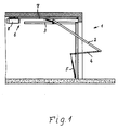
- Figure 1 shows a garage door generally designated 1 in a schematic semi-open position in the area of a garage entrance, the overhead door leaf (2) - swinging door leaf - by means of rollers mounted in the area of the upper inner edge in horizontal guide rails and otherwise by a steering linkage 4 in a known manner Is guided and on which a weight compensation spring 5 engages.
- the horizontal guide rail 3, the link 4 and the spring 5 are only shown with respect to one side region of the door and are provided in the same way for the other side of the door.
- a drive unit In the ceiling area of the garage, a drive unit, generally designated 6, is fixedly arranged in a known manner, which has a slide guide rail 7, which extends parallel to the horizontal guide rails 3, and a drive housing 8. There is a slide in the slide guide rail 7 guided in a longitudinally displaceable manner, which is fastened on the one hand to a displacement device embodied in the rail as an endless chain or endless belt and on the other hand is connected to the door leaf via a steering linkage.
- the transport device is moved back and forth by the drive shaft of a direct current motor with a subsequent gear such that the slide can be moved in the slide guide rail between two end positions, in one of which the connected door leaf is in its closed position and in the other in its open position.
- the DC motor with subsequent gear and a control device for moving the door leaf are located in the drive housing 8.
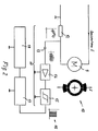
- FIG. 2 shows a schematic block diagram for the acquisition of the movement-dependent pulse train.
- a detector device 11 is switched on in the supply circuit for the DC motor 9, the commutator 10 of which is shown next to the motor symbol for clarification, in such a way that a resistor 12 in the supply circuit is connected in series with the collector 10 of the motor 9, on which the supply current changes generated by the lamella transitions of the commutator 10 or the current reversal in the windings of the rotor winding connected to the lamellae occur as a correspondingly modeled direct current signal, as is indicated graphically below the resistance element 12.
- the modeled signal is tapped and passed through a filter element - here a capacitor - so that the direct current component is omitted and the current change occurs as an alternating current signal, as is indicated graphically between the capacitor 13 and an adjoining amplifier 14.
- the amplified signals are fed to a Schmitt trigger 15, at the output of which the pulse train appears as a rectangular pulse train 16.
- This pulse sequence is input into the counter 17 and compared with respect to the respectively achieved values with stored values which indicate the end positions of the door leaf, which is symbolized by the processor 18. If the counter reading and the stored value match, a switch-off signal is generated which interrupts the feed circuit for the DC motor 9.
- the symbol 9 for the DC motor relates only to its rotor supply and says nothing about the design of the stator. This can be of any design. Due to the coupling of the motor shaft to the door leaf in terms of gear, the speed of the motor shaft or its rotational movement is generally a synchronous image of the movement distance of the door leaf. The current peaks generated by the current reversal in the rotor coils when the motor 9 is running correspond in number to one another in synchronism with the rotary movement of the rotor and thus with the movement distance of the door leaf. Due to the large number of collector slats, this results in a high resolution for the rotary movement of the rotor shaft and thus the door leaf movement distance. This provides a more precise control of the end positions of the door leaf and a precise definition of the stored values corresponding to these end positions in the course of setting up the door operation.
Abstract
Description
Die Erfindung betrifft ein Tor oder dergleichen Verschließeinrichtung mit einem mittels eines elektrischen Gleichstrommotor-Antriebsaggregates zwischen Schließ- und Offenstellung bewegbaren ein- oder mehrteiligen Torblatt, an welches die Abtriebswelle des Antriebsaggregates getrieblich angeschlossen ist und dessen Bewegungsstrecke proportional durch eine Impulsfolge wiedergegeben wird, welche von der Drehbewegung einer Welle des Antriebsaggregates abgeleitet ist und die einer Zahleinrichtung in einer Auswerteschaltung zugeführt wird, deren Zählstände mit Speicherwerten für vorbestimmte bzw. zuvor eingegebene Torblattstellungen verglichen werden und bei Koinzidenz zu Steuersignalen für das Antriebsaggregat ausgewertet sind.The invention relates to a gate or the like closing device with a single or multi-part door leaf which can be moved between the closed and open positions by means of an electric direct current motor drive unit, to which the output shaft of the drive unit is connected in a gearbox and whose movement distance is reproduced proportionally by a pulse sequence which is generated by the Rotational movement of a shaft of the drive unit is derived and which is fed to a counting device in an evaluation circuit, the counter values are compared with stored values for predetermined or previously entered door leaf positions and are evaluated in the event of coincidence with control signals for the drive unit.
Unter den hier angesprochenen Toren oder dergleichen sollen neben eigentlichen Toren aller Art als Gebäude- oder Geländeabschluß auch Türen, Fenster, Rolladen, Markisen und so weiter verstanden werden, die einer motorischen Betätigung zugänglich sind.The gates or the like mentioned here are to be understood in addition to actual gates of all types as building or site closure also doors, windows, shutters, awnings and so on, which are accessible to a motorized operation.
Zur Vermeidung von in den Endlagen der Bewegungsstrecke des Torblattes angebrachten Endschaltern hat man bereits die Bewegungsstrecke durch eine Impulsfolge nachgebildet mit dem Erfolg, daß die Steuerung des Antriebes für die Abschlatung der Torblattbewegung in den Endstellungen durch Zählen der bewegungsstreckenabhängigen Impulsfolge und Vergleich mit die Endstellungen markierenden Speicherwerten auf kleinstem Raume untergebracht werden kann, beispielsweise in demselben Gehäuse wie der Antriebsmotor. Die Speicherwerte können dabei nach Installation des Tores durch Verfahren des Torblattes mittels Handsteuerung bzw. niedriger Antriebsgeschwindigkeit - Schleichgang - unter einzelnen der dabei abgegebenen Impulsfolge den tatsächlichen Gegebenheiten entsprechend festgelegt werden.In order to avoid limit switches attached in the end positions of the movement path of the door leaf, the movement path has already been simulated by means of a pulse train with the success that the control of the drive for the deduction of the door leaf movement in the end positions by counting the movement path-dependent pulse train and comparing it with stored values marking the end positions can be accommodated in the smallest space, for example in the same housing as the drive motor. The stored values can be determined after installing the door by moving the door leaf using manual control or low drive speed - creep speed - according to the actual conditions, using the pulse sequence given.
Aufgrund der - spielfreien oder doch zumindest annähernd spielfreien - getrieblichen Verbindung zwischen Torblatt und Abtriebswelle des Antriebsaggregates ist die Zahl der Umdrehungen dieser und anderer Wellen des Antriebsaggregates eine entsprechend genaue Wiedergabe der Bewegungsstrecke des Torblattes. Daher wird die der Bewegungsstrecke entsprechende Impulsfolge oder Impulszahl durch einen Wandler erzeugt, der an eine der Wellen des Antriebsaggregates angeordnet ist. Dabei kann es sich um eine radial geschlitzte Scheibe handeln, auf deren Schlitzanordnung eine Lichtschranke ausgerichtet ist, so daß die umlaufende Scheibe im Abstand der Schlitze am Ausgang der Lichtschranke Impulse erzeugt, oder es kann eine Magnetinduktionseinrichtung vorgesehen sein, bei der ein Dauermagnet mit einer Welle des Antriebes umläuft und in einer ortsfesten Spule Induktionsströme erzeugt. Diese bekannten Ausführungen sind hinsichtlich der besonderen Bauteile des Platzbedarfes, der Anfälligkeit gegen Verschmutzung etc. verhältnismäßig aufwendig. Auch ist die Auflösung, d.h. die Zahl der Impulse pro Streckenabschnitt beispielsweise einer Wellenumdrehung, eher gering, was der Genauigkeit des Einfahrens in die jeweilige Endstellung abträglich ist.Due to the gear connection between the door leaf and the output shaft of the drive unit, which is free of play or at least almost free of play, the number of revolutions of this and other shafts of the drive unit is a correspondingly accurate representation of the movement distance of the door leaf. The pulse sequence or number of pulses corresponding to the movement distance is therefore generated by a converter which is arranged on one of the shafts of the drive unit. This can be a radially slotted disk, on the slot arrangement of which a light barrier is aligned, so that the rotating disk generates pulses at the spacing of the slots at the exit of the light barrier, or a magnetic induction device can be provided in which a permanent magnet with a shaft of the drive rotates and generates induction currents in a fixed coil. These known designs are relatively expensive with regard to the special components of the space requirement, the susceptibility to contamination, etc. Also the resolution, i.e. the number of pulses per section of a shaft revolution, for example, is rather low, which is detrimental to the accuracy of moving into the respective end position.
Der Erfindung liegt die Aufgabe zugrunde, ein Tor mit einem Gleichstrom-Antriebsaggregat der eingangs genannten Art zur Verfügung zu stellen, dessen bewegungsstreckenabhängige Impulsfolgegewinnung wesentlich einfacher, raumsparend und betriebssicher ausgestaltet ist und eine hoche Auflösung gewährleistet.The invention has for its object to provide a gate with a DC drive unit of the type mentioned, the movement path dependent pulse train acquisition much easier, space-saving and is designed to be reliable and ensures high resolution.
Ausgehend von einem Tor mit Antrieb der eingangs genannten Art wird diese Aufgabe erfindungsgemäß dadurch gelöst, daß eine Detektoreinrichtung für die Erfassung von Speisestromänderungen des laufenden Gleichstrommotors, die durch dessen Kommutator veranlaßt sind, an deren Ausgang die der Bewegungsstrecke proportionale Impulsfolge auftritt.Starting from a gate with a drive of the type mentioned in the introduction, this object is achieved according to the invention in that a detector device for detecting feed current changes in the running DC motor, which are caused by its commutator, has the pulse sequence proportional to the movement path at its output.
Es ist ohne weiteres ersichtlich, daß diese Vorgehensweise praktisch keine insbesondere mechanischen Bauelemente benötigt, sondern vorhandene Einrichtungen, nämlich den Kommutator des Läufers des Gleichstrommotors, als Impulsbildner ausnutzt. Die Erzeugung der Impulsreihe geschieht also nur durch elektrotechnische Weiterverarbeitung und damit kleinräumig, verschmutzungsunabhängig und somit wartungsfrei, wobei eine hoche Auflösung, nämlich eine der Segmentzahl des Kommutators entsprechende Anzahl von Impulsen pro Motorwellenumdrehung erreicht wird. Diese Eigenschaften sind vom besonderen Wert für den Torblattantrieb, weil dort kleinräumig und möglichst wartungsarm sowie mit möglichst genauem Anfahren der Endlagen gearbeitet werden muß. Dabei ist weiteren von besonderem Vorteil, daß die Festlegung der den Endstellungen des Torblattes entsprechenden Speicherwerte in einer Speichereinrichtung durch Zählen mit eben der vorgeschilderten Impulsfolge zu Beginn des Torbetriebes und gegebenenfalls in zyklisch korrigierter Weise auch während der nachfolgenden Betriebszeit praktisch ohne weiteren Aufwand möglich ist.It is readily apparent that this procedure requires practically no mechanical components in particular, but rather uses existing devices, namely the commutator of the rotor of the DC motor, as a pulse generator. The generation of the pulse series thus only takes place through further electrical processing and thus on a small scale, regardless of contamination and thus maintenance-free, with a high resolution, namely a number of pulses per motor shaft revolution corresponding to the number of segments of the commutator. These properties are of particular value for the door leaf drive, because they have to be small-scale and as low-maintenance as possible, and the end positions must be approached as precisely as possible. It is also of particular advantage that the storage values corresponding to the end positions of the door leaf can be determined in a memory device by counting with the pulse sequence described at the beginning of the door operation and possibly in a cyclically corrected manner even during the subsequent operating time without any further effort.
Die mit dem Kommutator bewerkstelligte Stromwendung in den Wicklungsschleifen des Motorläufers macht sich in bekannter Weise als rhythmische Stromänderung im Speisestromkreis des Motorläufers bemerkbar, und zwar regelmäßig in Form eines durch die Kommutatorlamellenübergänge bedingten überlagerten Gleichstroms. Diese Speisestromänderung kann mittels eines Detektors erfaßt werden, wobei berührungslos arbeitende elektromagnetische Detektoren in Frage kommen. In besonders einfacher Weise wird ein Widerstandselement in den Speisestromkreis eingeschaltet, was grundsätzlich in Parallelschaltung zum Bürstenpaar des Kommutators geschehen könnte, vorzugsweise jedoch in Reihenschaltung zu diesen geschieht. Sofern das so gewonnene pulsierende Signal nicht ohne weiteres sicher genug verarbeitbar ist, läßt es sich aufbereiten, beispielsweise derart, daß man nach Ausfiltern oder Aussieben des Gleichstromeanteiles eine Verstärkung und eine Impulsformung vornimmt. Die mit einem solchen Antrieb besonders vorteilhaft zu betreibenden Tore sind insbesondere Garagenschwingtore, Deckengliedertore, Rolltore, Schiebetore und dergleichen. Insbesondere solche die aufgrund des Gleichstrommotors und dessen einfacher Drehzahlsteuerung mit gegenüber der Betriebsgeschwindigkeit niedrigerer Geschwindigkeit in eine oder beide Endlagen verfahrbar sind.The current reversal in the winding loops of the motor rotor, which is accomplished with the commutator, manifests itself in a known manner as a rhythmic current change in the feed circuit of the motor rotor, and in fact in the form of a superimposed direct current caused by the commutator lamellar transitions. This change in the feed current can be detected by means of a detector, contactless electromagnetic detectors being considered. In a particularly simple manner, a resistance element is switched on in the supply circuit, which is basically in parallel with the Brush pair of the commutator could happen, but preferably happens in series with these. If the pulsating signal obtained in this way cannot easily be processed safely enough, it can be processed, for example in such a way that amplification and pulse shaping are carried out after filtering out or sifting out the DC component. The gates to be operated particularly advantageously with such a drive are, in particular, overhead garage doors, sectional gates, roller gates, sliding gates and the like. In particular, those which, owing to the direct current motor and its simple speed control, can be moved into one or both end positions at a lower speed than the operating speed.
Die Erfindung wird anhand des in der Zeichnung wiedergegebenen Ausführungsbeispieles nachstehend näher erläutert. Es zeigen:
Figur 1 einen Vertikalschnitt senkrecht zur Fläche der Garagenöffnung mit schematischer Wiedergabe eines Tores und dessen Antriebsaggregat;Figur 2 eine schematische Schaltskizze für die Ableitung und Aufbereitung einer durch Kommutatordrehung erzeugten, wegstreckenabhängigen Impulsfolge.
- Figure 1 shows a vertical section perpendicular to the surface of the garage opening with a schematic representation of a gate and its drive unit;
- Figure 2 is a schematic circuit diagram for the derivation and preparation of a path-dependent pulse train generated by commutator rotation.
Figur 1 zeigt ein insgesamt mit 1 bezeichnetes Garagentor in schematischer Halboffen-Stellung im Bereich einer Garageneinfahrt, dessen über Kopf bewegbares Torblatt (2) - Schwingtorblatt - mittels im Bereich der oberen Innenkante gelagerten Rollen in horizontalen Führungsschienen und im übrigen durch ein Lenkgestänge 4 in bekannter Weise geführt ist und an dem eine Gewichtsausgleichsfeder 5 angreift. Die horizontale Führungsschiene 3, der Lenker 4 und der Feder 5 sind nur hinsichtlich eines Seitenbereiches des Tores dargestellt und in gleicher Weise für die andere Torseite vorgesehen.Figure 1 shows a garage door generally designated 1 in a schematic semi-open position in the area of a garage entrance, the overhead door leaf (2) - swinging door leaf - by means of rollers mounted in the area of the upper inner edge in horizontal guide rails and otherwise by a
In Deckenbereich der Garage ist in bekannter Weise ein insgesamt mit 6 bezeichnetes Antriebsaggregat ortsfest angeordnet, das eine Schlittenführungsschiene 7, die sich parallel zu den horizontalen Führungsschienen 3 erstreckt, und ein Antriebsgehäuse 8 aufweist. In der Schlittenführungsschiene 7 ist ein Schlitten längsverschiebbar geführt, der einerseits an einer in der Schiene als Endloskette oder Endlosband ausgebildeten Verschiebeeinrichtung befestigt ist und andererseits über ein Lenkgestänge mit dem Torblatt in Verbindung steht. Die Transporteinrichtung wird von der Antriebswelle eines Gleichstrommotors mit anschließendem Getriebe derart hin- und hergehend bewegt, daß der Schlitten in der Schlittenführungsschiene zwischen zwei Endstellungen verschiebbar ist, in deren einer das angeschlossene Torblatt in seiner Schließstellung und in deren anderer in seiner Offenstellung ist. Der Gleichstrommotor mit anschließendem Getriebe sowie eine Steuerungseinrichtung für das Verfahren des Torblattes befinden sich im Antriebsgehäuse 8.In the ceiling area of the garage, a drive unit, generally designated 6, is fixedly arranged in a known manner, which has a
Figur 2 zeigt ein schematisiertes Blockschaltbild für die Gewinnung der bewegungsstreckenabhängigen Impulsfolge. Zu diesem Zwecke ist in den Speisestromkreis für den Gleichstrommotor 9, dessen Kommutator 10 zur Verdeutlichung neben dem Motorsymbol wiedergegeben ist, eine Detektoreinrichtung 11 derart eingeschaltet, daß in Reihe zu dem Kollektor 10 des Motors 9 ein Widerstand 12 in den Speisestromkreis eingeschaltet ist, an welchem die bei laufenden Motor durch die Lamellenübergänge des Kommutators 10 bzw. die Stromwendung in den an die Lamellen angeschlossenen Windungen der Rotorwicklung erzeugten Speisestromänderungen als entsprechend modelliertes Gleichstromsignal auftritt, wie dies unterhalb des Widerstandselementes 12 grafisch angedeutet ist. Das modellierte Signal wird abgegriffen und über ein Siebglied - hier ein Kondensator - geleitet, so daß der Gleichstromanteil entfällt und die Stromänderung als Wechselstromsignal auftritt, wie dies zwischen dem Kondensator 13 und einem sich daran anschließenden Verstärker 14 grafisch angedeutet ist. Die verstärkten Signale werden einem Schmitt-Trigger 15 zugeleitet, an dessen Ausgang die Impulsfolge als Rechteckimpulsreihe 16 auftritt. Diese Impulsfolge wird in die Zähleinrichtung 17 eingegeben und hinsichtlich der jeweils erreichten Werte mit gespeicherten Werten verglichen, die die Endstellungen des Torblattes angeben, was durch den Prozessor 18 symbolisiert ist. Bei Übereinstimmung von Zählerstand und Speicherwert wird ein Abschaltsignal erzeugt, des den Speisestromkreis für den Gleichstrommotor 9 unterbricht.Figure 2 shows a schematic block diagram for the acquisition of the movement-dependent pulse train. For this purpose, a
Das Symbol 9 für den Gleichstrommotor betrifft nur dessen Rotorspeisung und sagt über die Ausgestaltung des Stators nichts aus. Dieser kann beliebig ausgebildet sein. Aufgrund der Ankopplung der Motorwelle getrieblich an das Torblatt ist die Drehzahl der Motorwelle bzw. dessen Drehbewegung allgemein ein synchrones Abbild der Bewegungsstrecke des Torblattes. Die bei laufenden Motor 9 durch die Stromwendung in den Rotorspulen erzeugten Stromspitzen entsprechen in der Zahl ihrer Aufeinanderfolge somit synchron der Drehbewegung des Rotors und damit der Bewegungsstrecke des Torblattes. Aufgrund der Vielzahl von Kollektorlamellen ergibt sich somit eine hoche Auflösung für die Drehbewegung der Rotorwelle und damit die Torblattbewegungsstrecke. Wodurch eine genauere Ansteuerung der Endstellungen des Torblattes wie auch eine genaue Festlegung der diesen Endstellungen entsprechenden Speicherwerte im Zuge der Einrichtung des Torbetriebes gegeben ist.The
Claims (8)
gekennzeichnet durch
eine Detektoreinrichtung (11) für die Erfassung von Speisestromänderungen des laufenden Gleichstrommotors (9), die durch dessen Kommutator (10) veranlaßt sind, an deren Ausgang die der Bewegungsstrecke proportionale Impulsfolge (16) auftritt.Gate or similar closing device with a single or multi-part door leaf (2) which can be moved between the closed and open positions by means of an electric direct current motor drive unit (9, 6), to which the output shaft of the drive unit is connected in a gearbox and whose movement distance is proportional to a pulse train (16 ) is reproduced, which is derived from the rotary movement of a shaft of the drive unit (6) and which is fed to a counting device (17) in an evaluation circuit (17, 18), the counted values of which are compared with stored values for predetermined or previously entered door leaf positions and at Coincidence with control signals for the drive unit (6) are evaluated,
marked by
a detector device (11) for the detection of feed current changes of the running direct current motor (9), which are caused by its commutator (10), at the output of which the pulse train (16) proportional to the movement distance occurs.
dadurch gekennzeichnet,
daß die Detektoreinrichtung (11) ein elektrisches Widerstandselement (12) aufweist.Gate according to claim 1,
characterized by
that the detector device (11) has an electrical resistance element (12).
dadurch gekennzeichnet,
daß das elektrische Widerstandselement (12) in Reihe zu dem Kommutator (10) des Gleichstrommotors (9) geschaltet ist.Gate according to claim 2,
characterized by
that the electrical resistance element (12) is connected in series to the commutator (10) of the DC motor (9).
dadurch gekennzeichnet,
daß die Detektoreinrichtung (11) ein Siebglied (13) aufweist.Gate according to one of claims 1 to 3,
characterized by
that the detector device (11) has a sieve member (13).
dadurch gekennzeichnet,
daß die Detektoreinrichtung (11) einen Impulsformer, beispielsweise Schmitt-Trigger (15), aufweist.Gate according to one of claims 1 to 4,
characterized by
that the detector device (11) has a pulse shaper, for example Schmitt trigger (15).
dadurch gekennzeichnet,
daß das Torblatt als über Kopf bewegbares Garagen-Schwingtorblatt (2) ausgebildet ist.Gate according to one of claims 1 to 5,
characterized by
that the door leaf is designed as an overhead swing door leaf (2).
dadurch gekennzeichnet,
daß das Torblatt als Deckengliedertorblatt ausgebildet ist.Gate according to one of claims 1 to 5,
characterized by
that the door leaf is designed as a ceiling link door leaf.
dadurch gekennzeichnet ,
daß das Torblatt (2) mittels des Gleichstrommotors (9) mit gegenüber der übrigen Geschwindigkeit verringerter Geschwindigkeit in die Schließ- und/oder Offenstellung verfahrbar gesteuert ist.Gate according to one of claims 1 to 7,
characterized by
that the door leaf (2) is controlled by means of the direct current motor (9) at a reduced speed compared to the rest of the speed in the closed and / or open position.
Applications Claiming Priority (2)
| Application Number | Priority Date | Filing Date | Title |
|---|---|---|---|
| DE19521538A DE19521538A1 (en) | 1995-06-13 | 1995-06-13 | Gate or the like with an electric drive unit |
| DE19521538 | 1995-06-13 |
Publications (3)
| Publication Number | Publication Date |
|---|---|
| EP0748915A2 true EP0748915A2 (en) | 1996-12-18 |
| EP0748915A3 EP0748915A3 (en) | 1998-06-10 |
| EP0748915B1 EP0748915B1 (en) | 2001-03-14 |
Family
ID=7764298
Family Applications (1)
| Application Number | Title | Priority Date | Filing Date |
|---|---|---|---|
| EP96109521A Expired - Lifetime EP0748915B1 (en) | 1995-06-13 | 1996-06-13 | Door or similar with electrical drive unit |
Country Status (3)
| Country | Link |
|---|---|
| EP (1) | EP0748915B1 (en) |
| AT (1) | ATE199762T1 (en) |
| DE (2) | DE19521538A1 (en) |
Cited By (2)
| Publication number | Priority date | Publication date | Assignee | Title |
|---|---|---|---|---|
| WO1997023946A1 (en) * | 1995-12-21 | 1997-07-03 | Hörmann KG Antriebstechnik | Current supply device for a d.c. motor drive system, especially comprising travel-dependent detection of parameters of the driven object |
| DE102007021567A1 (en) * | 2007-05-08 | 2008-11-20 | Siemens Ag | Door for door leaf actuation, has door leaf between its opened and closed position and partly leads translational movement with rotary drive, which has drive shaft, and door leaf position monitoring device is provided |
Families Citing this family (1)
| Publication number | Priority date | Publication date | Assignee | Title |
|---|---|---|---|---|
| DE29716482U1 (en) * | 1997-09-13 | 1999-01-14 | Hoermann Kg Antriebstechnik | Movement distance detection device for the control of an object driven by an electric motor |
Citations (6)
| Publication number | Priority date | Publication date | Assignee | Title |
|---|---|---|---|---|
| US4338553A (en) * | 1979-12-04 | 1982-07-06 | Scott Jr Waller M | Control system for a motor actuated door operating mechanism |
| EP0213992A1 (en) * | 1985-07-18 | 1987-03-11 | Jaeger | Method and device to control a DC motor |
| US4684858A (en) * | 1985-09-03 | 1987-08-04 | Capetronic (Bsr) Ltd. | Motor pulse extraction system |
| US5132602A (en) * | 1990-10-02 | 1992-07-21 | Calsonic International, Inc. | Actuator positioning apparatus |
| EP0499884A1 (en) * | 1991-02-20 | 1992-08-26 | Siemens Aktiengesellschaft | Process and apparatus for operating control of an automatic door |
| DE4138194A1 (en) * | 1991-11-18 | 1993-05-19 | Brose Fahrzeugteile | Detecting position and motion direction of translationally and/or rotationally moving system - comparing sensor pulses with motor ripple pulses and correcting corresponding path lengths or angle settings |
Family Cites Families (1)
| Publication number | Priority date | Publication date | Assignee | Title |
|---|---|---|---|---|
| DE3539265A1 (en) * | 1985-11-06 | 1987-05-07 | Audi Ag | Control circuit |
-
1995
- 1995-06-13 DE DE19521538A patent/DE19521538A1/en not_active Withdrawn
-
1996
- 1996-06-13 DE DE59606569T patent/DE59606569D1/en not_active Expired - Fee Related
- 1996-06-13 AT AT96109521T patent/ATE199762T1/en not_active IP Right Cessation
- 1996-06-13 EP EP96109521A patent/EP0748915B1/en not_active Expired - Lifetime
Patent Citations (6)
| Publication number | Priority date | Publication date | Assignee | Title |
|---|---|---|---|---|
| US4338553A (en) * | 1979-12-04 | 1982-07-06 | Scott Jr Waller M | Control system for a motor actuated door operating mechanism |
| EP0213992A1 (en) * | 1985-07-18 | 1987-03-11 | Jaeger | Method and device to control a DC motor |
| US4684858A (en) * | 1985-09-03 | 1987-08-04 | Capetronic (Bsr) Ltd. | Motor pulse extraction system |
| US5132602A (en) * | 1990-10-02 | 1992-07-21 | Calsonic International, Inc. | Actuator positioning apparatus |
| EP0499884A1 (en) * | 1991-02-20 | 1992-08-26 | Siemens Aktiengesellschaft | Process and apparatus for operating control of an automatic door |
| DE4138194A1 (en) * | 1991-11-18 | 1993-05-19 | Brose Fahrzeugteile | Detecting position and motion direction of translationally and/or rotationally moving system - comparing sensor pulses with motor ripple pulses and correcting corresponding path lengths or angle settings |
Cited By (2)
| Publication number | Priority date | Publication date | Assignee | Title |
|---|---|---|---|---|
| WO1997023946A1 (en) * | 1995-12-21 | 1997-07-03 | Hörmann KG Antriebstechnik | Current supply device for a d.c. motor drive system, especially comprising travel-dependent detection of parameters of the driven object |
| DE102007021567A1 (en) * | 2007-05-08 | 2008-11-20 | Siemens Ag | Door for door leaf actuation, has door leaf between its opened and closed position and partly leads translational movement with rotary drive, which has drive shaft, and door leaf position monitoring device is provided |
Also Published As
| Publication number | Publication date |
|---|---|
| ATE199762T1 (en) | 2001-03-15 |
| DE59606569D1 (en) | 2001-04-19 |
| DE19521538A1 (en) | 1997-01-09 |
| EP0748915A3 (en) | 1998-06-10 |
| EP0748915B1 (en) | 2001-03-14 |
Similar Documents
| Publication | Publication Date | Title |
|---|---|---|
| EP0974479B1 (en) | Method for the regulation of motor driven adjusting device in motor vehicle | |
| DE19910854C2 (en) | Electric window device | |
| EP0552459B1 (en) | Safety device for roller shutters and similar closures | |
| EP0751274A1 (en) | Actuator | |
| EP0899847B1 (en) | Method for determining the position and the direction of movement of a movable part driven by an electric motor | |
| DE4138194C2 (en) | Method and device for detecting the position and direction of movement of units which are moved in a translatory and / or rotary manner | |
| EP0771923A2 (en) | Movement monitor for a single or multiple panel door or gate | |
| DE2640045C3 (en) | Device for the automatic control of a door between its closed and its open position | |
| WO2000014843A1 (en) | Drive device and method for moving a vehicle part | |
| DE4315637A1 (en) | Method for detecting the position, the direction (sense) of rotation and/or the speed of rotation of a rotatably mounted part | |
| EP1292459B1 (en) | Method for determining the position of an element driven by the drive shaft of a direct current motor | |
| DE19639501A1 (en) | Door or window motorised vane | |
| DE3346242A1 (en) | Method for driving a window-shutter drive motor, and a controller for carrying out the method | |
| DE19809628B4 (en) | Drive device for moving a component such as window pane, sunroof of a vehicle | |
| EP0748915A2 (en) | Door or similar with electrical drive unit | |
| EP1008233B1 (en) | Current supply device for a d.c. motor drive system, especially comprising travel-dependent detection of parameters of the driven object | |
| EP3555572A1 (en) | Method and device for determining a position oof an actuating element | |
| DE19523241A1 (en) | Method of monitoring , controlling or regulating electrical actuator drives e.g. for doors, gates, windows or light fittings | |
| EP0710559B1 (en) | Drive for positioning in a printing press | |
| DE4438851C2 (en) | Device for controlling a motor drive | |
| EP0650107A1 (en) | Control system for motorized drives | |
| EP0808985A2 (en) | Roller door with control of the roller shutter | |
| EP0054581B1 (en) | Drive for controlling doors or portals | |
| EP0544132B1 (en) | Method and device for avoiding the overheating of electric motors | |
| DE102006051847A1 (en) | Movement detecting device for electrically operating sliding door, has molding arranged on traction-shear-cable that pulls and/or pushes sliding door, where drive wheel is provided for moving traction-shear-cable |
Legal Events
| Date | Code | Title | Description |
|---|---|---|---|
| PUAI | Public reference made under article 153(3) epc to a published international application that has entered the european phase |
Free format text: ORIGINAL CODE: 0009012 |
|
| AK | Designated contracting states |
Kind code of ref document: A2 Designated state(s): AT BE CH DE DK ES FR GB IT LI NL SE |
|
| RAP1 | Party data changed (applicant data changed or rights of an application transferred) |
Owner name: HOERMANN KG ANTRIEBSTECHNIK |
|
| PUAL | Search report despatched |
Free format text: ORIGINAL CODE: 0009013 |
|
| AK | Designated contracting states |
Kind code of ref document: A3 Designated state(s): AT BE CH DE DK ES FR GB IT LI NL SE |
|
| 17P | Request for examination filed |
Effective date: 19981106 |
|
| GRAG | Despatch of communication of intention to grant |
Free format text: ORIGINAL CODE: EPIDOS AGRA |
|
| 17Q | First examination report despatched |
Effective date: 20000802 |
|
| GRAG | Despatch of communication of intention to grant |
Free format text: ORIGINAL CODE: EPIDOS AGRA |
|
| GRAH | Despatch of communication of intention to grant a patent |
Free format text: ORIGINAL CODE: EPIDOS IGRA |
|
| GRAH | Despatch of communication of intention to grant a patent |
Free format text: ORIGINAL CODE: EPIDOS IGRA |
|
| GRAA | (expected) grant |
Free format text: ORIGINAL CODE: 0009210 |
|
| AK | Designated contracting states |
Kind code of ref document: B1 Designated state(s): AT BE CH DE DK ES FR GB IT LI NL SE |
|
| PG25 | Lapsed in a contracting state [announced via postgrant information from national office to epo] |
Ref country code: NL Free format text: LAPSE BECAUSE OF FAILURE TO SUBMIT A TRANSLATION OF THE DESCRIPTION OR TO PAY THE FEE WITHIN THE PRESCRIBED TIME-LIMIT Effective date: 20010314 |
|
| REF | Corresponds to: |
Ref document number: 199762 Country of ref document: AT Date of ref document: 20010315 Kind code of ref document: T |
|
| REG | Reference to a national code |
Ref country code: CH Ref legal event code: EP |
|
| ET | Fr: translation filed | ||
| REF | Corresponds to: |
Ref document number: 59606569 Country of ref document: DE Date of ref document: 20010419 |
|
| PG25 | Lapsed in a contracting state [announced via postgrant information from national office to epo] |
Ref country code: AT Free format text: LAPSE BECAUSE OF NON-PAYMENT OF DUE FEES Effective date: 20010613 |
|
| ITF | It: translation for a ep patent filed |
Owner name: SOCIETA' ITALIANA BREVETTI S.P.A. |
|
| PG25 | Lapsed in a contracting state [announced via postgrant information from national office to epo] |
Ref country code: SE Free format text: LAPSE BECAUSE OF FAILURE TO SUBMIT A TRANSLATION OF THE DESCRIPTION OR TO PAY THE FEE WITHIN THE PRESCRIBED TIME-LIMIT Effective date: 20010614 Ref country code: DK Free format text: LAPSE BECAUSE OF FAILURE TO SUBMIT A TRANSLATION OF THE DESCRIPTION OR TO PAY THE FEE WITHIN THE PRESCRIBED TIME-LIMIT Effective date: 20010614 |
|
| PG25 | Lapsed in a contracting state [announced via postgrant information from national office to epo] |
Ref country code: LI Free format text: LAPSE BECAUSE OF NON-PAYMENT OF DUE FEES Effective date: 20010630 Ref country code: CH Free format text: LAPSE BECAUSE OF NON-PAYMENT OF DUE FEES Effective date: 20010630 Ref country code: BE Free format text: LAPSE BECAUSE OF NON-PAYMENT OF DUE FEES Effective date: 20010630 |
|
| GBT | Gb: translation of ep patent filed (gb section 77(6)(a)/1977) |
Effective date: 20010619 |
|
| NLV1 | Nl: lapsed or annulled due to failure to fulfill the requirements of art. 29p and 29m of the patents act | ||
| PG25 | Lapsed in a contracting state [announced via postgrant information from national office to epo] |
Ref country code: ES Free format text: LAPSE BECAUSE OF FAILURE TO SUBMIT A TRANSLATION OF THE DESCRIPTION OR TO PAY THE FEE WITHIN THE PRESCRIBED TIME-LIMIT Effective date: 20010927 |
|
| BERE | Be: lapsed |
Owner name: HORMANN K.G. ANTRIEBSTECHNIK Effective date: 20010630 |
|
| REG | Reference to a national code |
Ref country code: GB Ref legal event code: IF02 |
|
| PLBE | No opposition filed within time limit |
Free format text: ORIGINAL CODE: 0009261 |
|
| STAA | Information on the status of an ep patent application or granted ep patent |
Free format text: STATUS: NO OPPOSITION FILED WITHIN TIME LIMIT |
|
| REG | Reference to a national code |
Ref country code: CH Ref legal event code: PL |
|
| 26N | No opposition filed | ||
| PGFP | Annual fee paid to national office [announced via postgrant information from national office to epo] |
Ref country code: IT Payment date: 20090624 Year of fee payment: 14 |
|
| PGFP | Annual fee paid to national office [announced via postgrant information from national office to epo] |
Ref country code: FR Payment date: 20090625 Year of fee payment: 14 |
|
| PGFP | Annual fee paid to national office [announced via postgrant information from national office to epo] |
Ref country code: GB Payment date: 20090603 Year of fee payment: 14 Ref country code: DE Payment date: 20090820 Year of fee payment: 14 |
|
| GBPC | Gb: european patent ceased through non-payment of renewal fee |
Effective date: 20100613 |
|
| REG | Reference to a national code |
Ref country code: FR Ref legal event code: ST Effective date: 20110228 |
|
| PG25 | Lapsed in a contracting state [announced via postgrant information from national office to epo] |
Ref country code: IT Free format text: LAPSE BECAUSE OF NON-PAYMENT OF DUE FEES Effective date: 20100613 |
|
| PG25 | Lapsed in a contracting state [announced via postgrant information from national office to epo] |
Ref country code: DE Free format text: LAPSE BECAUSE OF NON-PAYMENT OF DUE FEES Effective date: 20110101 |
|
| PG25 | Lapsed in a contracting state [announced via postgrant information from national office to epo] |
Ref country code: FR Free format text: LAPSE BECAUSE OF NON-PAYMENT OF DUE FEES Effective date: 20100630 |
|
| PG25 | Lapsed in a contracting state [announced via postgrant information from national office to epo] |
Ref country code: GB Free format text: LAPSE BECAUSE OF NON-PAYMENT OF DUE FEES Effective date: 20100613 |