EP0755694B1 - Guiding catheter introducer assembly - Google Patents
Guiding catheter introducer assembly Download PDFInfo
- Publication number
- EP0755694B1 EP0755694B1 EP96112026A EP96112026A EP0755694B1 EP 0755694 B1 EP0755694 B1 EP 0755694B1 EP 96112026 A EP96112026 A EP 96112026A EP 96112026 A EP96112026 A EP 96112026A EP 0755694 B1 EP0755694 B1 EP 0755694B1
- Authority
- EP
- European Patent Office
- Prior art keywords
- guiding catheter
- tubular body
- introducer
- assembly
- catheter
- Prior art date
- Legal status (The legal status is an assumption and is not a legal conclusion. Google has not performed a legal analysis and makes no representation as to the accuracy of the status listed.)
- Expired - Lifetime
Links
Images


Classifications
-
- A—HUMAN NECESSITIES
- A61—MEDICAL OR VETERINARY SCIENCE; HYGIENE
- A61M—DEVICES FOR INTRODUCING MEDIA INTO, OR ONTO, THE BODY; DEVICES FOR TRANSDUCING BODY MEDIA OR FOR TAKING MEDIA FROM THE BODY; DEVICES FOR PRODUCING OR ENDING SLEEP OR STUPOR
- A61M25/00—Catheters; Hollow probes
- A61M25/01—Introducing, guiding, advancing, emplacing or holding catheters
- A61M25/06—Body-piercing guide needles or the like
- A61M25/0662—Guide tubes
-
- A—HUMAN NECESSITIES
- A61—MEDICAL OR VETERINARY SCIENCE; HYGIENE
- A61M—DEVICES FOR INTRODUCING MEDIA INTO, OR ONTO, THE BODY; DEVICES FOR TRANSDUCING BODY MEDIA OR FOR TAKING MEDIA FROM THE BODY; DEVICES FOR PRODUCING OR ENDING SLEEP OR STUPOR
- A61M25/00—Catheters; Hollow probes
- A61M25/0043—Catheters; Hollow probes characterised by structural features
- A61M25/005—Catheters; Hollow probes characterised by structural features with embedded materials for reinforcement, e.g. wires, coils, braids
-
- A—HUMAN NECESSITIES
- A61—MEDICAL OR VETERINARY SCIENCE; HYGIENE
- A61M—DEVICES FOR INTRODUCING MEDIA INTO, OR ONTO, THE BODY; DEVICES FOR TRANSDUCING BODY MEDIA OR FOR TAKING MEDIA FROM THE BODY; DEVICES FOR PRODUCING OR ENDING SLEEP OR STUPOR
- A61M25/00—Catheters; Hollow probes
- A61M25/0097—Catheters; Hollow probes characterised by the hub
Definitions
- the present invention relates to an intravascular guiding catheter assembly, for use in the insertion and removal of medical devices and/or fluids into a blood vessel of a patient.
- the Hillstead US-A-5,066,285 discloses a catheter introducer with a sheath made of an expanded fibrous plastic, for gaining temporary entry into a patient's blood vessel with the use of a dilator.
- a catheter can subsequently be inserted into a patient's blood vessel after removal of the dilator through a hemostasis valve, located at the distal end of the catheter introducer sheath.
- the sheath features flexibility without kinking and high hoop strength.
- the Hibbs et al. US-A-5,300,032 discloses a catheter introducer with a rigid tubular body and a soft flexible tubular tip formed from a polymer material, such that the tip can navigate a greater curvature of a vessel wall without buckling. Attached to the proximal end of the tubular body is a valve and seal structure to prevent leakage during insertion and placement of the catheter.
- the Fischell et al. US-A-5,324,262 discloses an introducer sheath with an inflatable collar.
- the inflatable collar can be expanded to fit snugly against the edges of an opening in the blood vessel wall formed by the insertion of the introducer sheath to prevent blood leakage through the blood vessel wall.
- a proximal section of the sheath is a proximal fitting containing a hemoscasis valve.
- the Fischell et al. US-A-5,389,090 discloses a guiding catheter with an attached Touhy-Borst fitting.
- the guiding catheter uses a dilator and a guide wire to direct the catheter to its destination within a patient's artery without requiring an introducer sheath.
- a flexible kink-resistant introducer sheath which comprises an inner tube with a passageway longitudinally therethrough; a coil having a plurality of turns positioned longitudinally and compression fitted around said inner tube, whereby said turns have been compression fitted about the inner tube by winding the turns of the coil around the inner tube; and also an outer tube which is positioned longitudinally around said coil and said inner tube and which contacts the inner tube through the spaces left between the turns of the coil.
- a guiding catheter introducer assembly according to the features of claim 1.
- Such an assembly includes a catheter introducer sheath, with a hemostasis valve, attached or molded to a reinforced guiding catheter tube into a single assembly.
- the reinforced guiding catheter tube comprises a braided wire reinforced tubular body.
- the catheter introducer sheath further includes a side port at which point a stop cock can be attached or molded, again part of the single assembly, to facilitate the insertion and withdrawal of fluids.
- a braided wire reinforced guiding catheter tube into a catheter introducer assembly with a hemostasis valve attached thereto having a stopcock valve connected thereto into a single assembly, such assembly allows a physician to insert and place the guiding catheter directly into the body and start inserting medical devices through the hemostasis valve with minimal leakage of body fluids. Also liquids can be easily inserted into or withdrawn from the patient through the stopcock valve.
- the guiding catheter introducer assembly 10 includes a catheter sheath introducer body 12 integrally attached to a guiding catheter tubular body 14.
- the guiding catheter tubular body 14 (shown in FIGS. 3 and 4) has a stiff braid reinforced body similar to the catheter 10 body described in US-A-4,665,604.
- a soft tip 15 is provided and is void of the stiff braid reinforcing.
- a side port 16 extends laterally outward from the catheter sheath introducer body 12. Integrally attached to the side port 16 is a multiport stop cock 18 via a tubing 20. The interior of tubing 20 couples to side port 16 and allows fluids to transfer through the catheter introducer body 12 to the guiding catheter tubular body 14 from the side port 16 and the multiport stop cock 18.
- the tip 15 is coated with a radiopaque material such that it is visible on an x-ray machine when inserted into the patient.
- a radiopaque material such that it is visible on an x-ray machine when inserted into the patient.
- FIG. 2 there is illustrated therein an enlarged view of the guiding catheter introducer assembly 10, highlighting in greater detail the catheter sheath introducer body 12 and the multiport stop cock 18.
- the multiport stop cock 18 has two side ports 24 and 26 and a lever 28 for opening and closing a path between the opening at the end of the side ports 24 and 26 and the interior of the tubing 20. Additionally, shown attached to side port 24 is a Luer-lock TM connector 30. The multiport stop cock 18 allows fluids to be injected and withdrawn simultaneously as needed by the user.
- the catheter sheath introducer body 12 has an opening 32 at the proximal end 33 of the catheter sheath introducer body 12.
- the opening 32 allows the user to insert or remove medical devices through the guiding catheter introducer assembly 10 into and out of the blood vessel and direct them to a desired location in the patient's body.
- a rotatable annular flange 34 Molded to the side of the catheter sheath introducer body 12 is a rotatable annular flange 34 with an eyelet 36.
- the eyelet 36 can be used as a suture ring allowing the guiding catheter introducer assembly 10 to be stitched to the patient after the guiding catheter introducer assembly 10 has been inserted. This prevents movement of the guiding catheter introducer assembly 10 after it is secured in place.
- FIG. 5 there is illustrated a catheter sheath introducer body 12 with an end cap portion 38 removed and separated from a proximal end 33 of the body 12.
- a hemostasis valve partition 40 Within the catheter sheath introducer body 12, normally adjacent to the opening 32, is a hemostasis valve partition 40.
- the hemostasis valve partition 40 prevents the flow of fluids or gasses through the opening 32 when the user inserts or removes a medical device, such as an angioplasty balloon assembly into the patient through the guiding catheter introducer assembly 10.
- FIG. 6 shows a plan view of the hemostasis valve partition 40
- FIG. 7 shows an elevational view of the hemostasis valve partition 40.
- Through the center of the valve partition 40 are cut slits in the form of a plurality of radii 42.
- the radii 42 are rotated in a helical manner to a depth 44 between two-thirds to three-quarters of the overall thickness of valve partition 40.
- the slits continue to extend at a reduced and diminishing diameter 46 until the slits extend the rest of the way through the end 48 of the valve partition 40.
- the hemostasis valve partition 40 is preferably made of silicone rubber, but a variety of elastomers may also be used.
- hemostasis valve partition can be used in the assembly 10 and still achieve the benefits described and inherent in the present invention.
- the length of the guiding catheter tubular body 14 of the preferred embodiment of the guiding catheter introducer assembly 10 is minimally 80 centimeters in length, and preferably 100 to 110 centimeters, and has a central passageway which has a preferred diameter of 3 mm (French 9.)
- a guiding catheter tubular body 14 with a length of approximately 100 will be able to reach most locations within the heart blood vessels to which a user should wish to access.
- A. guiding catheter tubular body 14 with a central passageway of diameter 3 mm French 9 will allow access for most devices, i.e. balloon catheters, which need to be inserted into the blood vessel including an additional guiding catheter.
- the catheter sheath introducer body 12 is attached directly to the guiding catheter tubular body 14 as a single assembly, there is no need for assembly and disassembly of the unit for any reason, by the end user. Additionally only a single entry into the blood vessel wall is necessary, thereby reducing the trauma associated with entry into the blood vessel.
- the user merely inserts and places the guiding catheter introducer assembly 10 into position and starts inserting medical devices through the opening 32 and hemostasis valve partition 40 of the catheter sheath introducer body 12, as well as injection of agents or removal of fluids through the stop cock 18.
- the user removes the entire assembly 10 and closes the blood vessel entry point.
Description
- The present invention relates to an intravascular guiding catheter assembly, for use in the insertion and removal of medical devices and/or fluids into a blood vessel of a patient.
- Heretofore, various guiding and introducer catheters have been proposed. Several examples of analogous and non-analagous guiding and introducer catheter assemblies are disclosed in the following US-Patents: US-A-5,066,285 to Hillstead, US-A-5,300,032 to Hibbs et al, US-A-5,324,262 and US-A-5,389,090 both to Fischell et al.
- The Hillstead US-A-5,066,285 discloses a catheter introducer with a sheath made of an expanded fibrous plastic, for gaining temporary entry into a patient's blood vessel with the use of a dilator. A catheter can subsequently be inserted into a patient's blood vessel after removal of the dilator through a hemostasis valve, located at the distal end of the catheter introducer sheath. The sheath features flexibility without kinking and high hoop strength.
- The Hibbs et al. US-A-5,300,032 discloses a catheter introducer with a rigid tubular body and a soft flexible tubular tip formed from a polymer material, such that the tip can navigate a greater curvature of a vessel wall without buckling. Attached to the proximal end of the tubular body is a valve and seal structure to prevent leakage during insertion and placement of the catheter.
- The Fischell et al. US-A-5,324,262 discloses an introducer sheath with an inflatable collar. The inflatable collar can be expanded to fit snugly against the edges of an opening in the blood vessel wall formed by the insertion of the introducer sheath to prevent blood leakage through the blood vessel wall. At a proximal section of the sheath is a proximal fitting containing a hemoscasis valve.
- The Fischell et al. US-A-5,389,090 discloses a guiding catheter with an attached Touhy-Borst fitting. The guiding catheter uses a dilator and a guide wire to direct the catheter to its destination within a patient's artery without requiring an introducer sheath.
- In document EP 617 977 A1 a flexible kink-resistant introducer sheath is disclosed which comprises an inner tube with a passageway longitudinally therethrough; a coil having a plurality of turns positioned longitudinally and compression fitted around said inner tube, whereby said turns have been compression fitted about the inner tube by winding the turns of the coil around the inner tube; and also an outer tube which is positioned longitudinally around said coil and said inner tube and which contacts the inner tube through the spaces left between the turns of the coil. These introducer sheaths are both kink-resistant and thin-walled.
- According to the present invention there is provided a guiding catheter introducer assembly according to the features of claim 1. Such an assembly includes a catheter introducer sheath, with a hemostasis valve, attached or molded to a reinforced guiding catheter tube into a single assembly. The reinforced guiding catheter tube comprises a braided wire reinforced tubular body. The catheter introducer sheath further includes a side port at which point a stop cock can be attached or molded, again part of the single assembly, to facilitate the insertion and withdrawal of fluids.
- By incorporating a braided wire reinforced guiding catheter tube into a catheter introducer assembly with a hemostasis valve attached thereto having a stopcock valve connected thereto into a single assembly, such assembly allows a physician to insert and place the guiding catheter directly into the body and start inserting medical devices through the hemostasis valve with minimal leakage of body fluids. Also liquids can be easily inserted into or withdrawn from the patient through the stopcock valve.
-
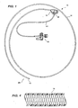
- FIG. 1 is a perspective view of one embodiment of a guiding catheter introducer assembly constructed to the teachings of the present invention;
- FIG. 2 is an exploded view of the same embodiment featured in FIG. 1 with the guiding catheter introducer assembly and a stop cock enlarged to show greater detail;
- FIG. 3 is a cross section of one embodiment of a reinforced guiding catheter tubular body of the assembly and is taken along line 3-3 of FIG. 2;
- FIG. 4 is a cross section of the same reinforced guiding catheter tubular body shown in FIG. 3 and is taken along line4-4 of FIG. 3;
- FIG. 5 is a partially exploded, perspective view of the guiding catheter sheath introducer assembly with an end capportion removed and separated from a proximal end of the assembly to show a hemostasis valve of the assembly;
- FIG. 6 is an enlarged plan view of the hemostasis valve partition; and
- FIG. 7 is an elevational view of the same hemostasis valve partition shown in FIG. 6 and is taken along line 7-7 of FIG 6.
- Referring now to the drawings in greater detail, there is illustrated in FIG. 1 a guiding catheter introducer
assembly 10 constructed according to the teachings of the present invention. The guiding catheter introducerassembly 10 includes a catheter sheath introducerbody 12 integrally attached to a guiding cathetertubular body 14. - The guiding catheter tubular body 14 (shown in FIGS. 3 and 4) has a stiff braid reinforced body similar to the
catheter 10 body described in US-A-4,665,604. Asoft tip 15 is provided and is void of the stiff braid reinforcing. - A
side port 16 extends laterally outward from the catheter sheath introducerbody 12. Integrally attached to theside port 16 is amultiport stop cock 18 via atubing 20. The interior oftubing 20 couples toside port 16 and allows fluids to transfer through the catheter introducerbody 12 to the guiding cathetertubular body 14 from theside port 16 and themultiport stop cock 18. - At a
distal end 22 of the guiding cathetertubular body 14, thetip 15 is coated with a radiopaque material such that it is visible on an x-ray machine when inserted into the patient. A more detailed description of such structure can be found in US-A-5,045,072, and in US-A-5,171,232. - Referring now to FIG. 2, there is illustrated therein an enlarged view of the guiding catheter introducer
assembly 10, highlighting in greater detail the catheter sheath introducerbody 12 and themultiport stop cock 18. - The
multiport stop cock 18 has twoside ports lever 28 for opening and closing a path between the opening at the end of theside ports tubing 20. Additionally, shown attached toside port 24 is a Luer-lock™ connector 30. Themultiport stop cock 18 allows fluids to be injected and withdrawn simultaneously as needed by the user. - The catheter sheath introducer
body 12 has an opening 32 at theproximal end 33 of the catheter sheath introducerbody 12. Theopening 32 allows the user to insert or remove medical devices through the guiding catheter introducerassembly 10 into and out of the blood vessel and direct them to a desired location in the patient's body. - Molded to the side of the catheter sheath introducer
body 12 is a rotatableannular flange 34 with aneyelet 36. Theeyelet 36 can be used as a suture ring allowing the guiding catheter introducerassembly 10 to be stitched to the patient after the guidingcatheter introducer assembly 10 has been inserted. This prevents movement of the guiding catheter introducerassembly 10 after it is secured in place. - In FIG. 5 there is illustrated a catheter sheath introducer
body 12 with an end cap portion 38 removed and separated from aproximal end 33 of thebody 12. Within the catheter sheath introducerbody 12, normally adjacent to theopening 32, is ahemostasis valve partition 40. Thehemostasis valve partition 40 prevents the flow of fluids or gasses through theopening 32 when the user inserts or removes a medical device, such as an angioplasty balloon assembly into the patient through the guiding catheter introducerassembly 10. - The
hemostasis valve partition 40 of the preferred embodiment is illustrated in FIG. 6 and FIG. 7. FIG. 6 shows a plan view of thehemostasis valve partition 40 and FIG. 7 shows an elevational view of thehemostasis valve partition 40. Through the center of thevalve partition 40 are cut slits in the form of a plurality ofradii 42. As the slits extend into thevalve partition 40 theradii 42 are rotated in a helical manner to adepth 44 between two-thirds to three-quarters of the overall thickness ofvalve partition 40. At which point the slits continue to extend at a reduced and diminishingdiameter 46 until the slits extend the rest of the way through theend 48 of thevalve partition 40. - The
hemostasis valve partition 40 is preferably made of silicone rubber, but a variety of elastomers may also be used. - Of course, another type of hemostasis valve partition can be used in the
assembly 10 and still achieve the benefits described and inherent in the present invention. - Because the guiding catheter introducer
assembly 10 is meant to incorporate the functionality of both an introducer sheath and a guiding catheter, the length of the guiding cathetertubular body 14 of the preferred embodiment of the guidingcatheter introducer assembly 10 is minimally 80 centimeters in length, and preferably 100 to 110 centimeters, and has a central passageway which has a preferred diameter of 3 mm (French 9.) - A guiding catheter
tubular body 14 with a length of approximately 100 will be able to reach most locations within the heart blood vessels to which a user should wish to access. A. guiding cathetertubular body 14 with a central passageway ofdiameter 3 mm French 9 will allow access for most devices, i.e. balloon catheters, which need to be inserted into the blood vessel including an additional guiding catheter. - Because the catheter
sheath introducer body 12 is attached directly to the guiding cathetertubular body 14 as a single assembly, there is no need for assembly and disassembly of the unit for any reason, by the end user. Additionally only a single entry into the blood vessel wall is necessary, thereby reducing the trauma associated with entry into the blood vessel. The user merely inserts and places the guidingcatheter introducer assembly 10 into position and starts inserting medical devices through theopening 32 andhemostasis valve partition 40 of the cathetersheath introducer body 12, as well as injection of agents or removal of fluids through thestop cock 18. When the user has completed the desired procedures, the user removes theentire assembly 10 and closes the blood vessel entry point. - From the foregoing description, it will be apparent that the guiding
catheter introducer assembly 10 of the present invention has a number of advantages, some of which have been described above and others of which are inherent in the invention. Also it will be understood that modifications can be made to the guiding catheter introducer assembly described above without departing from the teachings of the invention.
Claims (6)
- A guiding catheter introducer assembly (10) for insertion into a blood vessel of a patient comprising:a catheter sheath introducer body (12) with a hemostasis valve attached thereto and having a distal end, a proximal end (33) and a central passageway therethrough opening onto said proximal end and said distal end;a guiding catheter tubular body (14) having a distal end (22), a proximal end and a central passageway therethrough opening onto said proximal end and said distal end including a self supporting reinforced tubular body where said proximal end of said guiding catheter tubular body (14) is integrally attached to said distal end of said catheter sheath introducer body (12) as a single unit such that said central passageway of said catheter sheath introducer body (12) and said central passageway of said guiding catheter tubular body (14) form a common continuous passageway;said catheter sheath introducer body (12) having a side port (16) having a distal end, a proximal end and a central passageway therethrough opening into said proximal end and said distal end, said proximal end of said side port (16) being in communication with said opening in said central passageway of said catheter sheath introducer body (12); and a stop cock assembly (18) being integrally attached to the distal end of said side port (16); wherein said guiding catheter tubular body (14) further comprises a radiopaque tip (15) at the distal end (22) of said guiding catheter tubular body (15),characterized in thatthe self supporting reinforced tubular body is a self supporting wire braided reinforced tubular body including an elastomeric polyurethane resin and wherein said guiding catheter tubular body (14) has a length that is minimally 80 cm.
- The guiding catheter introducer assembly of claim 1, wherein said stop cock assembly (18) is a multiport stopcock assembly.
- The guiding catheter introducer assembly of claim 1 or 2, wherein said catheter sheath introducer body (12) further comprises a rotatable annular flange (34).
- The guiding catheter introducer assembly of claim 3, wherein said flange (34) further comprises an eyelet (36) for allowing the guiding catheter introducer assembly (10) to be sewn to the patient.
- The guiding catheter introducer assembly of anyone of claims 1 to 4, wherein the length of said guiding catheter tubular body (14) is between 100 centimeters and 110 centimeters.
- The guiding catheter introducer assembly of anyone of claims 1 to 5, wherein the diameter of said common continuous passageway is 3 mm (a size French 9.)
Applications Claiming Priority (2)
| Application Number | Priority Date | Filing Date | Title |
|---|---|---|---|
| US508098 | 1995-07-27 | ||
| US08/508,098 US5897497A (en) | 1995-07-27 | 1995-07-27 | Guiding catheter introducer assembly |
Publications (2)
| Publication Number | Publication Date |
|---|---|
| EP0755694A1 EP0755694A1 (en) | 1997-01-29 |
| EP0755694B1 true EP0755694B1 (en) | 2006-09-20 |
Family
ID=24021371
Family Applications (1)
| Application Number | Title | Priority Date | Filing Date |
|---|---|---|---|
| EP96112026A Expired - Lifetime EP0755694B1 (en) | 1995-07-27 | 1996-07-25 | Guiding catheter introducer assembly |
Country Status (3)
| Country | Link |
|---|---|
| US (1) | US5897497A (en) |
| EP (1) | EP0755694B1 (en) |
| DE (1) | DE69636562T2 (en) |
Cited By (1)
| Publication number | Priority date | Publication date | Assignee | Title |
|---|---|---|---|---|
| US9205244B2 (en) | 2009-06-29 | 2015-12-08 | Cook Medical Technologies Llc | Haemostatic valve device |
Families Citing this family (40)
| Publication number | Priority date | Publication date | Assignee | Title |
|---|---|---|---|---|
| US6004280A (en) | 1997-08-05 | 1999-12-21 | Cordis Corporation | Guiding sheath having three-dimensional distal end |
| US7314477B1 (en) | 1998-09-25 | 2008-01-01 | C.R. Bard Inc. | Removable embolus blood clot filter and filter delivery unit |
| US6595959B1 (en) | 1999-04-23 | 2003-07-22 | Alexander A. Stratienko | Cardiovascular sheath/catheter |
| US20070265563A1 (en) * | 2006-05-11 | 2007-11-15 | Heuser Richard R | Device for treating chronic total occlusion |
| US6712789B1 (en) * | 2000-07-13 | 2004-03-30 | Medamicus, Inc. | Introducer having a movable valve assembly with removable side port |
| US20030225379A1 (en) * | 2002-02-19 | 2003-12-04 | Medamicus, Inc. | Composite stasis valve |
| US9204956B2 (en) | 2002-02-20 | 2015-12-08 | C. R. Bard, Inc. | IVC filter with translating hooks |
| US7166088B2 (en) * | 2003-01-27 | 2007-01-23 | Heuser Richard R | Catheter introducer system |
| US7402141B2 (en) * | 2003-08-27 | 2008-07-22 | Heuser Richard R | Catheter guidewire system using concentric wires |
| US7704267B2 (en) | 2004-08-04 | 2010-04-27 | C. R. Bard, Inc. | Non-entangling vena cava filter |
| US8545418B2 (en) | 2004-08-25 | 2013-10-01 | Richard R. Heuser | Systems and methods for ablation of occlusions within blood vessels |
| US20090012429A1 (en) * | 2004-08-25 | 2009-01-08 | Heuser Richard R | Catheter guidewire system using concentric wires |
| US7771383B2 (en) * | 2004-10-22 | 2010-08-10 | Medegen, Inc. | Fluid control device with valve and methods of use |
| US7544187B2 (en) * | 2005-08-05 | 2009-06-09 | Merit Medical Systems, Inc. | Self-suturing anchor device |
| US7794473B2 (en) | 2004-11-12 | 2010-09-14 | C.R. Bard, Inc. | Filter delivery system |
| US20060142699A1 (en) * | 2004-12-23 | 2006-06-29 | Lampropoulos Fred P | Rotatable suture ring |
| US7803142B2 (en) | 2005-02-02 | 2010-09-28 | Summit Access Llc | Microtaper needle and method of use |
| US8267954B2 (en) * | 2005-02-04 | 2012-09-18 | C. R. Bard, Inc. | Vascular filter with sensing capability |
| US7967838B2 (en) | 2005-05-12 | 2011-06-28 | C. R. Bard, Inc. | Removable embolus blood clot filter |
| JP4851522B2 (en) | 2005-08-09 | 2012-01-11 | シー・アール・バード・インコーポレーテッド | Insertion type thrombus filter and delivery system |
| US8444602B2 (en) * | 2005-09-09 | 2013-05-21 | Cook Medical Technologies Llc | Hemostatic valve system |
| US8162894B2 (en) | 2005-09-09 | 2012-04-24 | Cook Medical Technologies Llc | Valve opener |
| EP1948074A2 (en) | 2005-11-18 | 2008-07-30 | C.R.Bard, Inc. | Vena cava filter with filament |
| US20070185567A1 (en) * | 2006-01-25 | 2007-08-09 | Heuser Richard R | Catheter system with stent device for connecting adjacent blood vessels |
| US8062321B2 (en) | 2006-01-25 | 2011-11-22 | Pq Bypass, Inc. | Catheter system for connecting adjacent blood vessels |
| WO2007133366A2 (en) | 2006-05-02 | 2007-11-22 | C. R. Bard, Inc. | Vena cava filter formed from a sheet |
| CA2655158A1 (en) | 2006-06-05 | 2007-12-13 | C.R. Bard Inc. | Embolus blood clot filter utilizable with a single delivery system or a single retrieval system in one of a femoral or jugular access |
| US8858608B2 (en) | 2007-12-10 | 2014-10-14 | Cook Medical Technologies Llc | Lubrication apparatus for a delivery and deployment device |
| US8308692B2 (en) | 2008-09-03 | 2012-11-13 | Cook Incorporated | Introducer for use in inserting a medical device into a body vessel and method for same |
| WO2010071856A1 (en) * | 2008-12-19 | 2010-06-24 | Tyco Healthcare Group, L.P. | Method and apparatus for storage and/or introduction of implant for hollow anatomical structure |
| CA2769208C (en) | 2009-07-29 | 2017-10-31 | C.R. Bard, Inc. | Tubular filter |
| US20110202038A1 (en) * | 2010-02-12 | 2011-08-18 | Sukhjit Gill | Guidewire positioning device |
| US9161759B2 (en) | 2011-06-24 | 2015-10-20 | Covidien Lp | Method and apparatus for storage and/or introduction of anatomical implant |
| JP3195511U (en) * | 2012-03-27 | 2015-01-29 | テルモ株式会社 | Introducer |
| CN104147678B (en) * | 2014-08-15 | 2016-06-01 | 汕头大学医学院第一附属医院 | A kind of arterial sheath collected with raffinate |
| US10449293B2 (en) * | 2015-03-20 | 2019-10-22 | Enable Injections, Inc. | Injection needle, injection apparatus employing same and method of making |
| US10010344B2 (en) | 2015-07-13 | 2018-07-03 | Dennis L Steffen | Self-dilating catheter introducer with obturator and method of use |
| EP4309724A3 (en) | 2016-02-18 | 2024-04-17 | Smiths Medical ASD, Inc. | Closed system catheter |
| USD808013S1 (en) | 2016-10-27 | 2018-01-16 | Smiths Medical Asd, Inc. | Catheter |
| US10737085B2 (en) | 2017-05-05 | 2020-08-11 | Greatbatch Ltd. | Medical device with hemostatic valve |
Family Cites Families (16)
| Publication number | Priority date | Publication date | Assignee | Title |
|---|---|---|---|---|
| US4665604A (en) * | 1982-02-16 | 1987-05-19 | Cordis Corporation | Non-fused torque control catheter |
| US4650472A (en) * | 1985-08-30 | 1987-03-17 | Cook, Incorporated | Apparatus and method for effecting percutaneous catheterization of a blood vessel using a small gauge introducer needle |
| US4950257A (en) * | 1988-09-15 | 1990-08-21 | Mallinckrodt, Inc. | Catheter introducer with flexible tip |
| US5045072A (en) * | 1989-06-13 | 1991-09-03 | Cordis Corporation | Catheter having highly radiopaque, flexible tip |
| US5066285A (en) * | 1990-01-26 | 1991-11-19 | Cordis Corporation | Catheter introducer sheath made of expanded polytetrafluoroethylene |
| US5380304A (en) * | 1991-08-07 | 1995-01-10 | Cook Incorporated | Flexible, kink-resistant, introducer sheath and method of manufacture |
| WO1993006878A1 (en) * | 1991-10-11 | 1993-04-15 | Boston Scientific Corporation | Catheter introducer sheath assembly |
| US5395349A (en) * | 1991-12-13 | 1995-03-07 | Endovascular Technologies, Inc. | Dual valve reinforced sheath and method |
| JPH06190052A (en) * | 1992-09-18 | 1994-07-12 | Cordis Corp | Catheter insertion equipment of which fiber is reinforced |
| JP3310031B2 (en) * | 1992-10-23 | 2002-07-29 | テルモ株式会社 | Catheter tube |
| US5324262A (en) * | 1993-02-09 | 1994-06-28 | Cathco, Inc. | Introducer sheath with expandable outer tube and method of use |
| US5538512A (en) * | 1993-02-25 | 1996-07-23 | Zenzon; Wendy J. | Lubricious flow directed catheter |
| US5423762A (en) * | 1993-04-15 | 1995-06-13 | Cordis Corporation | Modular catheter sheath introducer |
| US5413561A (en) * | 1993-05-13 | 1995-05-09 | Cathco, Inc. | Guiding catheter with sealing cap system for reducing blood loss when inserting guiding catheters |
| US5389090A (en) * | 1994-02-07 | 1995-02-14 | Cathco, Inc. | Guiding catheter with straightening dilator |
| US5558652A (en) * | 1994-10-06 | 1996-09-24 | B. Braun Medical, Inc. | Introducer with radiopaque marked tip and method of manufacture therefor |
-
1995
- 1995-07-27 US US08/508,098 patent/US5897497A/en not_active Expired - Lifetime
-
1996
- 1996-07-25 DE DE69636562T patent/DE69636562T2/en not_active Expired - Lifetime
- 1996-07-25 EP EP96112026A patent/EP0755694B1/en not_active Expired - Lifetime
Cited By (1)
| Publication number | Priority date | Publication date | Assignee | Title |
|---|---|---|---|---|
| US9205244B2 (en) | 2009-06-29 | 2015-12-08 | Cook Medical Technologies Llc | Haemostatic valve device |
Also Published As
| Publication number | Publication date |
|---|---|
| DE69636562D1 (en) | 2006-11-02 |
| EP0755694A1 (en) | 1997-01-29 |
| DE69636562T2 (en) | 2007-06-14 |
| US5897497A (en) | 1999-04-27 |
Similar Documents
| Publication | Publication Date | Title |
|---|---|---|
| EP0755694B1 (en) | Guiding catheter introducer assembly | |
| EP0771573B1 (en) | Kink resistant catheter sheath introducer | |
| US6544247B1 (en) | Introducer system | |
| US5382238A (en) | Catheter stiffeners | |
| EP1698369B1 (en) | Catheter assembly | |
| EP0839549B1 (en) | Catheter having an expandable shaft | |
| JP4940390B2 (en) | Medical device having knitted structure and coil | |
| EP1681073B1 (en) | Multi lumen catheter | |
| US7494478B2 (en) | Catheter assembly | |
| EP0829270B1 (en) | Preshaped catheter for angiocardiography | |
| US5221255A (en) | Reinforced multiple lumen catheter | |
| EP0440992B1 (en) | Reinforced multiple-lumen catheter | |
| US6328730B1 (en) | Endoluminal multi-luminal surgical sheath and method | |
| US5853394A (en) | Catheter | |
| US5466230A (en) | Catheter sheath introducer with strain relief | |
| EP1349486B1 (en) | Micro catheter and guidewire system having improved pushability and control | |
| US5209741A (en) | Surgical access device having variable post-insertion cross-sectional geometry | |
| EP1631343B1 (en) | Flexible introducer sheath with varying durometer | |
| US20140194857A1 (en) | Catheter with an enhanced pushability | |
| CN117279688A (en) | Dilator and catheter assembly |
Legal Events
| Date | Code | Title | Description |
|---|---|---|---|
| PUAI | Public reference made under article 153(3) epc to a published international application that has entered the european phase |
Free format text: ORIGINAL CODE: 0009012 |
|
| AK | Designated contracting states |
Kind code of ref document: A1 Designated state(s): DE FR GB IT NL |
|
| 17P | Request for examination filed |
Effective date: 19970723 |
|
| 17Q | First examination report despatched |
Effective date: 20050513 |
|
| GRAP | Despatch of communication of intention to grant a patent |
Free format text: ORIGINAL CODE: EPIDOSNIGR1 |
|
| GRAS | Grant fee paid |
Free format text: ORIGINAL CODE: EPIDOSNIGR3 |
|
| GRAA | (expected) grant |
Free format text: ORIGINAL CODE: 0009210 |
|
| AK | Designated contracting states |
Kind code of ref document: B1 Designated state(s): DE FR GB IT NL |
|
| PG25 | Lapsed in a contracting state [announced via postgrant information from national office to epo] |
Ref country code: IT Free format text: LAPSE BECAUSE OF FAILURE TO SUBMIT A TRANSLATION OF THE DESCRIPTION OR TO PAY THE FEE WITHIN THE PRESCRIBED TIME-LIMIT;WARNING: LAPSES OF ITALIAN PATENTS WITH EFFECTIVE DATE BEFORE 2007 MAY HAVE OCCURRED AT ANY TIME BEFORE 2007. THE CORRECT EFFECTIVE DATE MAY BE DIFFERENT FROM THE ONE RECORDED. Effective date: 20060920 |
|
| REG | Reference to a national code |
Ref country code: GB Ref legal event code: FG4D |
|
| REF | Corresponds to: |
Ref document number: 69636562 Country of ref document: DE Date of ref document: 20061102 Kind code of ref document: P |
|
| ET | Fr: translation filed | ||
| PLBE | No opposition filed within time limit |
Free format text: ORIGINAL CODE: 0009261 |
|
| STAA | Information on the status of an ep patent application or granted ep patent |
Free format text: STATUS: NO OPPOSITION FILED WITHIN TIME LIMIT |
|
| 26N | No opposition filed |
Effective date: 20070621 |
|
| REG | Reference to a national code |
Ref country code: FR Ref legal event code: PLFP Year of fee payment: 20 |
|
| PGFP | Annual fee paid to national office [announced via postgrant information from national office to epo] |
Ref country code: NL Payment date: 20150709 Year of fee payment: 20 |
|
| PGFP | Annual fee paid to national office [announced via postgrant information from national office to epo] |
Ref country code: DE Payment date: 20150722 Year of fee payment: 20 Ref country code: GB Payment date: 20150722 Year of fee payment: 20 |
|
| PGFP | Annual fee paid to national office [announced via postgrant information from national office to epo] |
Ref country code: FR Payment date: 20150629 Year of fee payment: 20 |
|
| PGFP | Annual fee paid to national office [announced via postgrant information from national office to epo] |
Ref country code: IT Payment date: 20150727 Year of fee payment: 20 |
|
| REG | Reference to a national code |
Ref country code: DE Ref legal event code: R071 Ref document number: 69636562 Country of ref document: DE |
|
| REG | Reference to a national code |
Ref country code: NL Ref legal event code: MK Effective date: 20160724 |
|
| REG | Reference to a national code |
Ref country code: GB Ref legal event code: PE20 Expiry date: 20160724 |
|
| PG25 | Lapsed in a contracting state [announced via postgrant information from national office to epo] |
Ref country code: GB Free format text: LAPSE BECAUSE OF EXPIRATION OF PROTECTION Effective date: 20160724 |