EP0759276A2 - Improved shock absorbing cushion - Google Patents
Improved shock absorbing cushion Download PDFInfo
- Publication number
- EP0759276A2 EP0759276A2 EP96113194A EP96113194A EP0759276A2 EP 0759276 A2 EP0759276 A2 EP 0759276A2 EP 96113194 A EP96113194 A EP 96113194A EP 96113194 A EP96113194 A EP 96113194A EP 0759276 A2 EP0759276 A2 EP 0759276A2
- Authority
- EP
- European Patent Office
- Prior art keywords
- cushion
- fluid
- compressible
- filaments
- elastomeric
- Prior art date
- Legal status (The legal status is an assumption and is not a legal conclusion. Google has not performed a legal analysis and makes no representation as to the accuracy of the status listed.)
- Granted
Links
Images


Classifications
-
- A—HUMAN NECESSITIES
- A43—FOOTWEAR
- A43B—CHARACTERISTIC FEATURES OF FOOTWEAR; PARTS OF FOOTWEAR
- A43B7/00—Footwear with health or hygienic arrangements
- A43B7/14—Footwear with health or hygienic arrangements with foot-supporting parts
- A43B7/1405—Footwear with health or hygienic arrangements with foot-supporting parts with pads or holes on one or more locations, or having an anatomical or curved form
- A43B7/141—Footwear with health or hygienic arrangements with foot-supporting parts with pads or holes on one or more locations, or having an anatomical or curved form having an anatomical or curved form
-
- A—HUMAN NECESSITIES
- A43—FOOTWEAR
- A43B—CHARACTERISTIC FEATURES OF FOOTWEAR; PARTS OF FOOTWEAR
- A43B13/00—Soles; Sole-and-heel integral units
- A43B13/02—Soles; Sole-and-heel integral units characterised by the material
- A43B13/04—Plastics, rubber or vulcanised fibre
-
- A—HUMAN NECESSITIES
- A43—FOOTWEAR
- A43B—CHARACTERISTIC FEATURES OF FOOTWEAR; PARTS OF FOOTWEAR
- A43B13/00—Soles; Sole-and-heel integral units
- A43B13/14—Soles; Sole-and-heel integral units characterised by the constructive form
- A43B13/18—Resilient soles
- A43B13/187—Resiliency achieved by the features of the material, e.g. foam, non liquid materials
-
- A—HUMAN NECESSITIES
- A43—FOOTWEAR
- A43B—CHARACTERISTIC FEATURES OF FOOTWEAR; PARTS OF FOOTWEAR
- A43B13/00—Soles; Sole-and-heel integral units
- A43B13/14—Soles; Sole-and-heel integral units characterised by the constructive form
- A43B13/18—Resilient soles
- A43B13/189—Resilient soles filled with a non-compressible fluid, e.g. gel, water
-
- A—HUMAN NECESSITIES
- A43—FOOTWEAR
- A43B—CHARACTERISTIC FEATURES OF FOOTWEAR; PARTS OF FOOTWEAR
- A43B17/00—Insoles for insertion, e.g. footbeds or inlays, for attachment to the shoe after the upper has been joined
- A43B17/02—Insoles for insertion, e.g. footbeds or inlays, for attachment to the shoe after the upper has been joined wedge-like or resilient
- A43B17/026—Insoles for insertion, e.g. footbeds or inlays, for attachment to the shoe after the upper has been joined wedge-like or resilient filled with a non-compressible fluid, e.g. gel, water
-
- A—HUMAN NECESSITIES
- A43—FOOTWEAR
- A43B—CHARACTERISTIC FEATURES OF FOOTWEAR; PARTS OF FOOTWEAR
- A43B17/00—Insoles for insertion, e.g. footbeds or inlays, for attachment to the shoe after the upper has been joined
- A43B17/02—Insoles for insertion, e.g. footbeds or inlays, for attachment to the shoe after the upper has been joined wedge-like or resilient
- A43B17/03—Insoles for insertion, e.g. footbeds or inlays, for attachment to the shoe after the upper has been joined wedge-like or resilient filled with a gas, e.g. air
- A43B17/035—Insoles for insertion, e.g. footbeds or inlays, for attachment to the shoe after the upper has been joined wedge-like or resilient filled with a gas, e.g. air provided with a pump or valve
-
- A—HUMAN NECESSITIES
- A43—FOOTWEAR
- A43B—CHARACTERISTIC FEATURES OF FOOTWEAR; PARTS OF FOOTWEAR
- A43B7/00—Footwear with health or hygienic arrangements
- A43B7/14—Footwear with health or hygienic arrangements with foot-supporting parts
- A43B7/1405—Footwear with health or hygienic arrangements with foot-supporting parts with pads or holes on one or more locations, or having an anatomical or curved form
- A43B7/1415—Footwear with health or hygienic arrangements with foot-supporting parts with pads or holes on one or more locations, or having an anatomical or curved form characterised by the location under the foot
- A43B7/142—Footwear with health or hygienic arrangements with foot-supporting parts with pads or holes on one or more locations, or having an anatomical or curved form characterised by the location under the foot situated under the medial arch, i.e. under the navicular or cuneiform bones
-
- A—HUMAN NECESSITIES
- A43—FOOTWEAR
- A43B—CHARACTERISTIC FEATURES OF FOOTWEAR; PARTS OF FOOTWEAR
- A43B7/00—Footwear with health or hygienic arrangements
- A43B7/14—Footwear with health or hygienic arrangements with foot-supporting parts
- A43B7/1405—Footwear with health or hygienic arrangements with foot-supporting parts with pads or holes on one or more locations, or having an anatomical or curved form
- A43B7/1415—Footwear with health or hygienic arrangements with foot-supporting parts with pads or holes on one or more locations, or having an anatomical or curved form characterised by the location under the foot
- A43B7/144—Footwear with health or hygienic arrangements with foot-supporting parts with pads or holes on one or more locations, or having an anatomical or curved form characterised by the location under the foot situated under the heel, i.e. the calcaneus bone
-
- A—HUMAN NECESSITIES
- A43—FOOTWEAR
- A43B—CHARACTERISTIC FEATURES OF FOOTWEAR; PARTS OF FOOTWEAR
- A43B7/00—Footwear with health or hygienic arrangements
- A43B7/14—Footwear with health or hygienic arrangements with foot-supporting parts
- A43B7/1405—Footwear with health or hygienic arrangements with foot-supporting parts with pads or holes on one or more locations, or having an anatomical or curved form
- A43B7/1415—Footwear with health or hygienic arrangements with foot-supporting parts with pads or holes on one or more locations, or having an anatomical or curved form characterised by the location under the foot
- A43B7/1445—Footwear with health or hygienic arrangements with foot-supporting parts with pads or holes on one or more locations, or having an anatomical or curved form characterised by the location under the foot situated under the midfoot, i.e. the second, third or fourth metatarsal
-
- F—MECHANICAL ENGINEERING; LIGHTING; HEATING; WEAPONS; BLASTING
- F16—ENGINEERING ELEMENTS AND UNITS; GENERAL MEASURES FOR PRODUCING AND MAINTAINING EFFECTIVE FUNCTIONING OF MACHINES OR INSTALLATIONS; THERMAL INSULATION IN GENERAL
- F16F—SPRINGS; SHOCK-ABSORBERS; MEANS FOR DAMPING VIBRATION
- F16F13/00—Units comprising springs of the non-fluid type as well as vibration-dampers, shock-absorbers, or fluid springs
- F16F13/002—Units comprising springs of the non-fluid type as well as vibration-dampers, shock-absorbers, or fluid springs comprising at least one fluid spring
-
- Y—GENERAL TAGGING OF NEW TECHNOLOGICAL DEVELOPMENTS; GENERAL TAGGING OF CROSS-SECTIONAL TECHNOLOGIES SPANNING OVER SEVERAL SECTIONS OF THE IPC; TECHNICAL SUBJECTS COVERED BY FORMER USPC CROSS-REFERENCE ART COLLECTIONS [XRACs] AND DIGESTS
- Y10—TECHNICAL SUBJECTS COVERED BY FORMER USPC
- Y10T—TECHNICAL SUBJECTS COVERED BY FORMER US CLASSIFICATION
- Y10T428/00—Stock material or miscellaneous articles
- Y10T428/13—Hollow or container type article [e.g., tube, vase, etc.]
- Y10T428/1352—Polymer or resin containing [i.e., natural or synthetic]
-
- Y—GENERAL TAGGING OF NEW TECHNOLOGICAL DEVELOPMENTS; GENERAL TAGGING OF CROSS-SECTIONAL TECHNOLOGIES SPANNING OVER SEVERAL SECTIONS OF THE IPC; TECHNICAL SUBJECTS COVERED BY FORMER USPC CROSS-REFERENCE ART COLLECTIONS [XRACs] AND DIGESTS
- Y10—TECHNICAL SUBJECTS COVERED BY FORMER USPC
- Y10T—TECHNICAL SUBJECTS COVERED BY FORMER US CLASSIFICATION
- Y10T428/00—Stock material or miscellaneous articles
- Y10T428/23—Sheet including cover or casing
- Y10T428/231—Filled with gas other than air; or under vacuum
-
- Y—GENERAL TAGGING OF NEW TECHNOLOGICAL DEVELOPMENTS; GENERAL TAGGING OF CROSS-SECTIONAL TECHNOLOGIES SPANNING OVER SEVERAL SECTIONS OF THE IPC; TECHNICAL SUBJECTS COVERED BY FORMER USPC CROSS-REFERENCE ART COLLECTIONS [XRACs] AND DIGESTS
- Y10—TECHNICAL SUBJECTS COVERED BY FORMER USPC
- Y10T—TECHNICAL SUBJECTS COVERED BY FORMER US CLASSIFICATION
- Y10T428/00—Stock material or miscellaneous articles
- Y10T428/23—Sheet including cover or casing
- Y10T428/233—Foamed or expanded material encased
-
- Y—GENERAL TAGGING OF NEW TECHNOLOGICAL DEVELOPMENTS; GENERAL TAGGING OF CROSS-SECTIONAL TECHNOLOGIES SPANNING OVER SEVERAL SECTIONS OF THE IPC; TECHNICAL SUBJECTS COVERED BY FORMER USPC CROSS-REFERENCE ART COLLECTIONS [XRACs] AND DIGESTS
- Y10—TECHNICAL SUBJECTS COVERED BY FORMER USPC
- Y10T—TECHNICAL SUBJECTS COVERED BY FORMER US CLASSIFICATION
- Y10T428/00—Stock material or miscellaneous articles
- Y10T428/23—Sheet including cover or casing
- Y10T428/237—Noninterengaged fibered material encased [e.g., mat, batt, etc.]
-
- Y—GENERAL TAGGING OF NEW TECHNOLOGICAL DEVELOPMENTS; GENERAL TAGGING OF CROSS-SECTIONAL TECHNOLOGIES SPANNING OVER SEVERAL SECTIONS OF THE IPC; TECHNICAL SUBJECTS COVERED BY FORMER USPC CROSS-REFERENCE ART COLLECTIONS [XRACs] AND DIGESTS
- Y10—TECHNICAL SUBJECTS COVERED BY FORMER USPC
- Y10T—TECHNICAL SUBJECTS COVERED BY FORMER US CLASSIFICATION
- Y10T428/00—Stock material or miscellaneous articles
- Y10T428/23—Sheet including cover or casing
- Y10T428/239—Complete cover or casing
-
- Y—GENERAL TAGGING OF NEW TECHNOLOGICAL DEVELOPMENTS; GENERAL TAGGING OF CROSS-SECTIONAL TECHNOLOGIES SPANNING OVER SEVERAL SECTIONS OF THE IPC; TECHNICAL SUBJECTS COVERED BY FORMER USPC CROSS-REFERENCE ART COLLECTIONS [XRACs] AND DIGESTS
- Y10—TECHNICAL SUBJECTS COVERED BY FORMER USPC
- Y10T—TECHNICAL SUBJECTS COVERED BY FORMER US CLASSIFICATION
- Y10T428/00—Stock material or miscellaneous articles
- Y10T428/249921—Web or sheet containing structurally defined element or component
- Y10T428/249953—Composite having voids in a component [e.g., porous, cellular, etc.]
- Y10T428/24996—With internal element bridging layers, nonplanar interface between layers, or intermediate layer of commingled adjacent foam layers
-
- Y—GENERAL TAGGING OF NEW TECHNOLOGICAL DEVELOPMENTS; GENERAL TAGGING OF CROSS-SECTIONAL TECHNOLOGIES SPANNING OVER SEVERAL SECTIONS OF THE IPC; TECHNICAL SUBJECTS COVERED BY FORMER USPC CROSS-REFERENCE ART COLLECTIONS [XRACs] AND DIGESTS
- Y10—TECHNICAL SUBJECTS COVERED BY FORMER USPC
- Y10T—TECHNICAL SUBJECTS COVERED BY FORMER US CLASSIFICATION
- Y10T428/00—Stock material or miscellaneous articles
- Y10T428/249921—Web or sheet containing structurally defined element or component
- Y10T428/249953—Composite having voids in a component [e.g., porous, cellular, etc.]
- Y10T428/249987—With nonvoid component of specified composition
- Y10T428/249988—Of about the same composition as, and adjacent to, the void-containing component
-
- Y—GENERAL TAGGING OF NEW TECHNOLOGICAL DEVELOPMENTS; GENERAL TAGGING OF CROSS-SECTIONAL TECHNOLOGIES SPANNING OVER SEVERAL SECTIONS OF THE IPC; TECHNICAL SUBJECTS COVERED BY FORMER USPC CROSS-REFERENCE ART COLLECTIONS [XRACs] AND DIGESTS
- Y10—TECHNICAL SUBJECTS COVERED BY FORMER USPC
- Y10T—TECHNICAL SUBJECTS COVERED BY FORMER US CLASSIFICATION
- Y10T442/00—Fabric [woven, knitted, or nonwoven textile or cloth, etc.]
- Y10T442/30—Woven fabric [i.e., woven strand or strip material]
- Y10T442/3472—Woven fabric including an additional woven fabric layer
- Y10T442/3504—Woven fabric layers comprise chemically different strand material
- Y10T442/3512—Three or more fabric layers
Definitions
- This invention relates to a shock absorbing cushion for athletic and industrial gear and footwear. More particularly, this invention relates to a shock absorbing cushion comprised of a sealed elastomeric envelope enclosing a compressible material and a fluid, wherein the compressible material is secured to the elastomeric envelope by a plurality of filaments, or a plurality of tensile elements forming the inner surface of said envelope material, and securely imbedded in said compressible material so as to substantially impede delamination between said envelope and said compressible material.
- the cushion is particularly well suited to absorb the impact experienced in athletic endeavors and effectively return energy to the athlete. More particularly, the cushion is well suited to the intense and repetitious impact which occurs in short intervals during athletic activities.
- numerous references will be made to use of the cushion as a portion of the sole of athletic footwear; however, it should be realized that the inventive cushion can be beneficially incorporated into various types of footwear including, but not limited to, dress shoes, boots, sandals, etc.
- the new cushioning device can provide protection in many types of athletic equipment where these unique cushioning and dynamic characteristics would be beneficial such as football, soccer, baseball, knee, leg, shoulder, neck and arm pads, saddles, helmets, gloves, seat cushions, etc.
- One common approach to impact absorption has involved using blocks of a compressible padding material.
- shoes have been constructed with cotton padding, horsehair padding, rubber, plastic foam, and the like.
- the inherent resilience of the compressible padding material is used to absorb and disperse impact.
- these materials are relatively inefficient in their ability to return energy to the shoe wearer and after repeated use become compacted and lose their cushioning properties.
- these designs experience full compression or "bottom out" quickly which results in severe impact stress on the wearer's body.
- the compressible padding material becomes cumbersome and heavy and can interfere with the design of the footwear and in an athlete's performance.
- instability may be encountered.
- foam inserts are preferred in athletic footwear because of their light weight and relatively favorable cushioning characteristics. Notwithstanding the superiority of foam within the compressible padding material group, it has been found that the cellular structure of a foam insert degrades with time and cyclic loading, resulting in collapse of the cell walls, and the corresponding rapid reduction in the cushioning characteristics of the insert. On the other hand, as opposed to the fluid inserts discussed below, foam and other compressible materials are not subject to instantaneous failure.
- shock absorbing devices which are based on the properties of fluids.
- these cushioning devices are comprised of a fluid encased within an elastomeric material.
- compressible fluids ex. gasses
- these devices rely primarily upon the compression of the enclosed fluid to provide the desired shock absorbance.
- incompressible fluids cushioning is provided primarily by the flow of the fluid and/or the expansion and contraction of chamber walls housing the fluid.
- fluid filled cushioning inserts provide superior overall cushioning and performance characteristics as compared to cushions constructed of foam and other compressible padding materials. Particularly, energy return is generally believed to be more efficient in fluid filled devices, and there is likely to be an increase in the longevity of the device. Moreover, the cushioning activity of fluids does not degrade with time. Only when the elastomeric material containing the fluid experiences structural failure or puncture does the device cease to perform at a high level. Accordingly, it is essential in compressible and incompressible fluid containing cushions to provide a long-lived elastomeric encasement. However, two competing design factors complicate this endeavor.
- a device having exceptional longevity can be achieved with a thick, strong, and durable elastomeric envelope.
- a thick envelope mitigates the benefits of fluid cushioning because the characteristics of the fluid are replaced and masked by those of the elastomeric material. Accordingly, it is desirable to have a thin walled envelope to obtain the maximum benefits of fluid cushioning.
- a thin, flexible envelope may have too short of a lifespan before rupture.
- the competing interests of intrusive versus unobtrusive envelopes arises when a particular shaped cushion is desired.
- fluids do not have an inherent shape. Therefore, the elastomeric material must assert shaping forces on the fluid. Obviously, a thick, strong elastomeric envelope can easily form complex shapes; however, the characteristics of the fluid medium are sacrificed.
- the elastomeric member can be made thin and flexible; however, control of fluid flow and/or compression are all sacrificed.
- U.S. Patent No. 4,219,945 wherein a multichambered pressurized gas-filled elastomeric envelope is encapsulated in a visco-elastic foam.
- the foam acts as a medium between a foot and the cushion and provides a smooth intermediate surface.
- a cushion is formed of rounded tubular chambers of a thin and unobtrusive elastomeric material to provide exceptional fluid support. The cushion is then encapsulated in foam to fill the peaks and valleys and provide a specifically shaped cushion with a long life.
- U.S. Patent No. 4,874,640 describes a composite cushion comprised of a flexible plastic enclosure forming an internal cavity.
- the enclosure is generally impermeable to air and generally filled with a fluid that can be pressurized.
- the composite also includes a compression, impact absorbing foam core glued or bonded on its external surfaces to the internal surface of the plastic enclosure.
- the patent also suggests reinforcing the internal foam cushioning member by including filaments, fibers or fabrics to the integrating matrix of the foam core.
- U.S. Patent No. 5,083,361 describes a pressurized gas inflated hermetically sealed barrier securely bonded on its inner surface to a double walled fabric structure.
- the double walled fabric structure is comprised of a first and second outer fabric layer spaced apart in a facing relationship yet interconnected with drop threads.
- the drop threads function essentially as tension members to position the opposing gas barrier surfaces in a precise geometric relationship from one to the other.
- the interconnected fabric layers are connected to distal interior surfaces of the elastomeric material via a coupling material which penetrates and bonds to the fabric layers.
- This device has found significant commercial success. However, this device is relatively complex and expensive to manufacture. In addition, it should be noted that this device is inoperable as a cushion subsequent to a rupture or leak in the elastomeric barrier member.
- the art is in need of a relatively inexpensive, long-lived, easy to manufacture, fluid containing cushioning device with controlled shape and cushioning characteristics.
- a particularly attractive means of achieving this end is the effective combination of fluid filled cushioning characteristics with the stability and reliability of compressible padding materials.
- a particularly significant advantage of a shock absorbing cushion having a fluid containing portion and an internally positioned compressible padding material is its superior shock absorbance and energy return in combination with an ability to be constructed in complicated shapes and provide cushioned support when the applied loads would otherwise bottom-out, especially in the event of fluid loss.
- the shock absorbing cushion of this invention comprises a flexible barrier envelope defining at least one sealed chamber containing a compressible material and a fluid.
- the compressible material is secured to the barrier envelope by means of filaments having a first portion embedded in the compressible material and a second portion embedded in the internal face of the flexible barrier envelope.
- filaments is utilized throughout this specification; however, this term is intended to encompass fibrils, threads, strands, whiskers, woven and nonwoven fabrics, fibers and all equivalents thereof.
- the compressible material will be comprised of foam and the fluid of a compressible gas or vapor.
- the foam material includes at least partially open cells, more preferably a urethane foam.
- the compressible material will be a composite body wherein a plurality of overlapping, reinforcing fibers, filaments, or threads are uniformly disbursed in a properly oriented manner, and securely imbedded within (in situ) a matrix of an appropriate elastomeric foam material.
- the reinforcing filaments alone or in combination with other filaments, can also act as the interconnecting members between the compressible flexible member and barrier envelope.
- the reinforcing filaments can extend from the surface of the foam member and be embedded in the flexible barrier envelope or visa versa.
- a surface abrasion technique can be used to expose and free ends of the imbedded tensile elements from the surface layer of the compressible member so they may be imbedded and secured into the flexible barrier member.
- the filaments as a chopped roving or as a fabric (woven or nonwoven) -- can be embedded in the outer surface of the compressible insert and in the inner surface of the elastomeric barrier envelope.
- the barrier envelope may include a plurality of small diameter contiguous, high strength elastomeric teat-like extensions or ridges protruding from its inner surface. These protrusions will extend into the filament reinforced compressible material and be securely bonded into the material. The protrusions are then embedded into the flexible barrier envelope to form a secure fatigue resistant engagement between the compressible member and flexible barrier envelope.
- the filaments which comprise the padding can be embedded into the barrier envelope.
- shoe 1 is comprised of an upper 2 constructed of leather, vinyl, nylon, or any other fabric or material utilized in the art, secured to a mid-sole 3.
- Mid-sole 3 is secured to an out-sole 5 having studs or other ground engaging elements 7 for traction purposes.
- mid-sole 3 and out-sole 5 can be formed as a single element if desired.
- the shock absorbing cushion of the subject invention is contained in mid-sole 3, within chamber 9.
- cushion 10 is comprised of an elastomeric barrier material 11 hermetically sealed to enclose a fluid (not shown). Also enclosed within barrier material 11 with the fluid is compressible insert 12. Compressible insert 12 may be reinforced with embedded filaments 13 which also secure the barrier material 11 to compressible insert 12. As best seen in the enlarged view FIG. 3, filaments 13 have a first portion 13a embedded in compressible insert 12 and a second portion 13b embedded in barrier material 11.
- shock absorbing cushions filled with one or more compressible fluids.
- a preferred fluid is a gas comprised of inert non-polar large molecules, alone or in combination with air.
- These devices can be self-inflating via diffusion pumping or mechanically inflated by means of a pump or pressure source in combination with a suitable valving arrangement.
- midsole 3 can optionally be provided with valve(s) 16, in sealed communication with the shock absorbing cushion 10.
- Gasses which have been found particularly suitable include the following: hexafluoroethane; sulfur hexafluoride; perfluoropropane; perfluorobutane; perfluoropentane; perfluorohexane; perfluoroheptane; octafluorocylcobutane; perfluorocyclobutane; hexafluoropropylene; tetrafluoromethane; monochloropentafluoroethane; 1,2-dichlorotetrafluoroethane; 1,1,2-trichloro-1,2,2-trifluoroethane; chlorotrifluoroethylene; bromotrifluoromethane; and, monochlorotrifluoromethane.
- Two preferred gasses within this group for use in the members are hexafluoroethane and sulfurhexafluoride in combination with nitrogen. These gases are identified in U.S. patents 4,340,626; 4,936,029; and 5,042,176 as "captive" gases which in combination with gases normally in the atmosphere surrounding the device that diffuse through the semi-permeable barrier film, i.e. "mobile” gases, pressurize the unit.
- incompressible fluids such as water, semi-gel liquids, oils, grease, soft or liquid wax, glycerine, soft soap, silicones, rheopexic fluids, thixotropic fluids, and corn syrups which exemplify but do not limit the types of acceptable incompressible liquids.
- a preferred incompressible liquid has a viscosity between 50 and 3000 centistokes, is non-toxic, is odorless, and is resistant to freezing at temperatures to which footwear is typically exposed.
- the flexible barrier member is preferably comprised of elastomeric materials selected from: polyurethane, polyester elastomer, fluoroelastomer, chlorinated polyethylene, polyvinyl chloride, chlorosulfonated polyethylene, polyethylene/ethylene vinyl acetate copolymer, neoprene, butadiene acrylonitrile rubber, butadiene styrene rubber, ethylene propylene polymer, natural rubber, high strength silicone rubber, low density polyethylene, adduct rubber, sulfide rubber, methyl rubber, vulcanizable rubber, polyvinyl alcohol and thermoplastic rubber.
- Polyurethane is a particularly preferred material for construction of the barrier.
- the barrier material may also be comprised of crystallographic diffusion controlling materials as defined in U.S. patents 4,936,029 and 5,042,176.
- Compressible insert 12 may be comprised of any padding material used in the cushioning and footwear art which provides support to both compressive and tensile forces, such as cotton, rubber, foam, horsehair, plastic mesh, etc.
- the compressible member is comprised of an at least partially open cell, flexible foam.
- Polyurethane or ethylene-vinyl acetate foams are preferred.
- any flexible, elastomeric foam common to those skilled in the cushioning and footwear art is suitable.
- the cushioning devices in particular, the fluid filling, flexible barrier materials and general cushion design (i.e. shape, number of chambers, position in a shoe, etc.) may be guided by the teachings in U.S. Patent Nos. 3,005,272; 3,685,176; 3,760,056; 4,183,156; 4,217,705; 4,219,945; 4,271,706; 4,287,250; 4,297,797; 4,340,626; 4,370,754; 4,471,538; 4,486,901; 4,506,460; 4,724,627; 4,779,359; 4,817,304; 4,829,682; 4,864,737; 4,864,738; 4,874,640; 4,906,502; 4,936,029; 5,036,603; 5,042,176; 5,083,361; 5,097,607; 5,155,927; 5,228,217; 5,235,715; 5,245,766; 5,283,963; 5,315,769
- the cushion of the subject invention can form a component of a footwear product in the heel portion, the metatarsal region, the arch of the foot region, any combination of these, or any location in which foot and/or other body part cushioning is desired by one skilled in the art.
- the preferred filament material joining the flexible barrier material 11 to compressible member 12 is comprised of polyesters, polyethylene terephthalate, polyamides, nylons, kevlar fiberglass, carbon, glass, silk, cotton, wool, urethane, aramide, dacron, cellulose, rayon, copra, acetate, polyvinyl alcohol, polyacrylics, and mixtures thereof.
- any sufficiently strong material which is compatible with the compressible insert and the barrier material is acceptable for use in forming the filaments.
- the joining material is not limited to filament-like compounds.
- the "filaments” can be a fabric texturized to have tendrils, fibers or even loops extending from both facing surfaces thereof. Included within fabrics are woven and nonwoven mats having fibers, tendrils, etc. extending from the surface.
- the discrete filaments have a denier per filament of between about 1 and 20 and a length sufficient to allow a first portion to embed in the flexible barrier material and a second portion to embed in the compressible insert.
- a preferred fiber reinforced interface will exhibit sufficient tensile strength to provide a separation or peel strength between the barrier layer and compressible insert of at least 5 lb's per linear inch.
- a preferred embodiment would have a peel strength of at least 13 lbs. per linear inch.
- the construction of a product or device utilizing the inventive cushion is particularly facilitated by the ability of the cushion to be constructed with custom shaped or contoured surfaces.
- the cross-section of the foam insert in FIG. 2 demonstrates relatively flat top 14 and bottom 15 surfaces.
- the foam insert and the corresponding elastomeric flexible barrier material applied thereto can be formed with a contoured surface.
- the shock absorbing cushion 110 is constructed to conform to the arch 114 of the foot by making compressible insert 112 thicker in that region 114. Chopped, orientated filaments or roving are shown properly disbursed in the foam. Accordingly, an extremely comfortable and highly efficient cushion is provided.
- the cushion 210 includes a raised portion 211 under the arch of the foot, the metatarsal arch of the foot region 213, and the in the center of the heel for extra cushioning at heel strike 214.
- the sections 8-8 and 9-9 correspond to the figures; 8 (metatarsal arch) and 9 (heel area).
- FIGS. 4A-4F which are enlarged for clarity, the excellent cushioning efficiencies of the inventive cushion are demonstrated.
- FIGS. 4A-F demonstrates the ability of the fluid filled portion of the cushioning insert to provide a comfortable feel, i.e. riding on air -- when compressible fluids are utilized --which upon exertion of force provides an exceptional and uniquely beneficial absorbance, distribution, storage, and return of energy.
- the compressible insert provides additional cushioned support and assurance against bottoming-out of the device.
- the filament interface 313 is seen joining compressible insert 312 to elastomeric barrier envelope 311.
- the foot experiences a "riding-on-air" type of support which provides a high degree of comfort.
- the pressure of the fluid supports the foot and there is very little compression of the device.
- This is depicted in the graph of Fig. 10, where the letters A-D on the abscissa of the graph refer to corresponding FIGURES 4A thru 4D.
- View B demonstrates a moderate amount of compression -- for example light running --wherein the elastomeric material 311 and fluid contained therein is compressed; however, the force is not significant enough to significantly deform the compressible insert 312 (see abscissa "B", FIG. 10). In this state, the compression of the fluid absorbs the majority of the force.
- View C demonstrates hard running -- wherein a more severe impact is experienced. It can be seen that in addition to compression of the fluid contained in elastomeric material 311, the compressible insert 312 begins to deform and share in the shock absorbance (abscissa "C", FIG. 10).
- a woven or nonwoven fabric can be texturized, flannelized or the equivalent, on each side to provide exposed filaments or loops on the surfaces of the fabric. These exposed portions can then be bonded to selected portions of the external surface of the compressible insert.
- a foam can be chemically or thermally partially cured to achieve a solid center and a tacky, penetrable surface. The texturized fabric, trimmed in advance or after attachment, is layed on and pressed into the penetrable surface. Final curing of the foam embeds the filaments therein, creating a secure bond.
- the elastomeric material in sheets or blow molded or otherwise pre-formed, are placed on the top and bottom surfaces of the fabric coated foam insert and secured to the filaments via flame treatment, ultrasound, I.R., microwave or RF heating or other method common to those skilled in the art, to at least partially melt the surface facing the filaments.
- flame treatment ultrasound, I.R., microwave or RF heating or other method common to those skilled in the art, to at least partially melt the surface facing the filaments.
- only the facing surface of the elastomeric sheet is melted to a controlled depth, allowing the exposed filaments to only partially penetrate the elastomeric member and embed therein. Only partial penetration is desired because a filament extending through the entirety of the barrier layer provides a "leak path" for fluid escape and eventual cushion failure.
- the elastomeric barrier envelope comprising at least one compression member is sealed at the perimeter, for example by RF welding.
- a fluid may then be transported into the sealed barrier envelope via activated diffusion, chamber to chamber transport, or injected mechanically by a needle or a valve --item 16 of FIG. 1-- to complete the cushion.
- the fabric can be replaced with a chopped or woven roving sprayed or otherwise flocked or eletrostatically uniformly disbursed and positioned onto the semi-cured surface of the compressible insert.
- the process can be reversed wherein the elastomeric envelope is prepared and a chopped roving or fabric is embedded onto its interior surface. Thereafter, a compressible insert is cured within the elastomeric envelope and allowed to embed the filaments.
- This method is particularly desirable because chopped filament roving can be readily secured to an elastomeric sheet or blow molded envelope when it is exposed to a heated platen or heated air, respectively.
- the exterior surface will cure first and allow partial filament penetration.
- the compressible insert can be constructed with filaments which extend beyond the outer walls of the compressible insert.
- the filaments extending from the surface will be trimmed to the desired length to facilitate application of the elastomeric barrier material and embedding therein.
- a filament reinforced compressible insert can be designed with finger-like or teat-like projections, with or without containing filament reinforcement.
- the fingers and inherently the filaments become embedded in the elastomeric barrier material.
- first and second portions of a sufficient length and quantity of filaments to achieve a peel strength preferably, at least 5 lbs. per linear inch, more preferably at least 13 lbs. per linear inch.
- compressible inserts comprised of woven, twisted, sewn or matted fibers or filaments, for example sewn cotton fiber pads, can simply be texturized to expose the desired amount of filaments which can be embedded in the elastomeric barrier envelope.
- the filaments are "embedded” and secured in the compressible insert directly as a result of their woven or matted construction.
- FIGS. 3 and 5A-E Examples of filament interface techniques, meant to demonstrate but not limit the invention, are provided in FIGS. 3 and 5A-E.
- the exposed ends of reinforcement filaments 13 are embedded in barrier member 11.
- FIG. 5A a plurality of chopped roving filaments 413 have been embedded in both elastomeric barrier member 411 and in compressible insert 412.
- compressible insert 512 includes finger like protrusions 514, which contain at least some ends of the reinforcing filaments 513. Since the protrusions 514 are embedded in elastomeric barrier member 511, the filaments 513 become embedded and secured therein as well.
- FIGS. 5C and 5D fabrics are demonstrated as the filament interface material.
- FIG. 5C and 5D fabrics are demonstrated as the filament interface material.
- a fabric 610 having a plurality of loops 613 provides the interface between compressible insert 612 and elastomeric barrier 611.
- a texturized fabric 710 having a plurality of exposed fibrils or filaments 713 secures elastomeric barrier layer 711 to the compressible insert 712.
- teat-like protrusions 813 form the internal surface of elastomeric barrier layer 811. These protrusions extend into compressible insert 812, contacting and securing layer 811 to fibers 814.
- the filament junction of the compressible insert and elastomeric barrier material can be supplemental with adhesive or a coupling layer attachment.
- Said compressible member may be shaped to conform to a human foot and may comprise urethane foam between two opposed substantially planar surfaces.
- Said flexible barrier material may comprise urethane.
- the cushion further may comprise at least 1000 embedded filaments per square inch.
- Said filaments may comprise a material selected from the group consisting of polyester, polyamide, nylon, fiberglass, carbon, polyethylene terephthalate, silk, cotton, wool, urethane, aramide, dacron, cellulose, rayon, copra, acetate, polyvinyl alcohol, polyacrylic, and mixtures thereof.
- Said filaments may have a denier per filament of between about 1 and 20 and preferably a tensile strength of from about 2 to 10 grams per denier.
- the separation strength of said barrier material from said compressible member may lie between about 5 to 40 pounds per linear inch.
- an adhesive may be provided securing said compressible member to said barrier material.
- a coupling layer may be disposed between said compressible member and said barrier material.
- a fluid impervious material surrounding said foam core as an envelope may be a semi-permeable elastomeric material, wherein said foam is an open cell foam, or a partially open cell foam.
- Said fluid may be compressible with said envelope having a gage pressure of at least 0 pounds per square inch. Alternatively, said fluid may be incompressible.
- Said filaments may be components of a fabric.
- An article of footwear according to the invention may comprise an envelope to house a foot and a sole portion comprised of an elastomeric material that is substantially impervious to a large molecule, non-polar gas, and is permeable to air in the shape of a cushion, said cushion containing a compressible insert and said gas, a plurality of filaments connecting said elastomeric material and said compressible insert.
- a shock absorbing cushioning device suitable for products, objects and footwear which is comprised of a compressible insert encapsulated within an elastomeric barrier member.
- the elastomeric barrier member is secured to the compressible insert by a plurality of tensile members having a first portion embedded in the elastomeric material and a second portion embedded in the compressible insert.
- the elastomeric member is also filled with a fluid, preferably a compressible gas.
Abstract

Description
- This invention relates to a shock absorbing cushion for athletic and industrial gear and footwear. More particularly, this invention relates to a shock absorbing cushion comprised of a sealed elastomeric envelope enclosing a compressible material and a fluid, wherein the compressible material is secured to the elastomeric envelope by a plurality of filaments, or a plurality of tensile elements forming the inner surface of said envelope material, and securely imbedded in said compressible material so as to substantially impede delamination between said envelope and said compressible material.
- The cushion is particularly well suited to absorb the impact experienced in athletic endeavors and effectively return energy to the athlete. More particularly, the cushion is well suited to the intense and repetitious impact which occurs in short intervals during athletic activities. Throughout the specification, numerous references will be made to use of the cushion as a portion of the sole of athletic footwear; however, it should be realized that the inventive cushion can be beneficially incorporated into various types of footwear including, but not limited to, dress shoes, boots, sandals, etc. In addition, the new cushioning device can provide protection in many types of athletic equipment where these unique cushioning and dynamic characteristics would be beneficial such as football, soccer, baseball, knee, leg, shoulder, neck and arm pads, saddles, helmets, gloves, seat cushions, etc.
- A great many shock absorbing devices exist in the footwear art to absorb the shock of foot strike. One common approach to impact absorption has involved using blocks of a compressible padding material. For example, shoes have been constructed with cotton padding, horsehair padding, rubber, plastic foam, and the like. In these shoes, the inherent resilience of the compressible padding material is used to absorb and disperse impact. However, these materials are relatively inefficient in their ability to return energy to the shoe wearer and after repeated use become compacted and lose their cushioning properties. Furthermore, on severe impacts, unless a relatively thick block of compressible padding is used, these designs experience full compression or "bottom out" quickly which results in severe impact stress on the wearer's body. When made thicker to avoid this problem, the compressible padding material becomes cumbersome and heavy and can interfere with the design of the footwear and in an athlete's performance. In addition, when the padding material is thick, instability may be encountered.
- Within the grouping of cushions constructed of compressible padding materials, foam inserts are preferred in athletic footwear because of their light weight and relatively favorable cushioning characteristics. Notwithstanding the superiority of foam within the compressible padding material group, it has been found that the cellular structure of a foam insert degrades with time and cyclic loading, resulting in collapse of the cell walls, and the corresponding rapid reduction in the cushioning characteristics of the insert. On the other hand, as opposed to the fluid inserts discussed below, foam and other compressible materials are not subject to instantaneous failure.
- To improve the characteristics of footwear cushions comprised of compressible padding materials, shock absorbing devices have been developed which are based on the properties of fluids. Usually, these cushioning devices are comprised of a fluid encased within an elastomeric material. In the case of compressible fluids (ex. gasses), these devices rely primarily upon the compression of the enclosed fluid to provide the desired shock absorbance. In the case of incompressible fluids, cushioning is provided primarily by the flow of the fluid and/or the expansion and contraction of chamber walls housing the fluid. In addition, there are devices based on the combination of compressible and incompressible fluids.
- It is believed that fluid filled cushioning inserts provide superior overall cushioning and performance characteristics as compared to cushions constructed of foam and other compressible padding materials. Particularly, energy return is generally believed to be more efficient in fluid filled devices, and there is likely to be an increase in the longevity of the device. Moreover, the cushioning activity of fluids does not degrade with time. Only when the elastomeric material containing the fluid experiences structural failure or puncture does the device cease to perform at a high level. Accordingly, it is essential in compressible and incompressible fluid containing cushions to provide a long-lived elastomeric encasement. However, two competing design factors complicate this endeavor.
- First, a device having exceptional longevity can be achieved with a thick, strong, and durable elastomeric envelope. However, a thick envelope mitigates the benefits of fluid cushioning because the characteristics of the fluid are replaced and masked by those of the elastomeric material. Accordingly, it is desirable to have a thin walled envelope to obtain the maximum benefits of fluid cushioning. Unfortunately, a thin, flexible envelope may have too short of a lifespan before rupture.
- Second, the competing interests of intrusive versus unobtrusive envelopes arises when a particular shaped cushion is desired. Moreover, fluids do not have an inherent shape. Therefore, the elastomeric material must assert shaping forces on the fluid. Obviously, a thick, strong elastomeric envelope can easily form complex shapes; however, the characteristics of the fluid medium are sacrificed. Of course, to highlight the desirable attributes of the fluid, the elastomeric member can be made thin and flexible; however, control of fluid flow and/or compression are all sacrificed.
- As indicated above, considerable difficulty has been experienced in providing shaped, fluid filled cushions, particularly pressurized cushions, with a flat or smoothly contoured surface. One very successful solution to this dilemma is provided in U.S. Patent No. 4,219,945 wherein a multichambered pressurized gas-filled elastomeric envelope is encapsulated in a visco-elastic foam. In this invention, the foam acts as a medium between a foot and the cushion and provides a smooth intermediate surface. Moreover, a cushion is formed of rounded tubular chambers of a thin and unobtrusive elastomeric material to provide exceptional fluid support. The cushion is then encapsulated in foam to fill the peaks and valleys and provide a specifically shaped cushion with a long life.
- Notwithstanding the success of foam encapsulated gas-filled cushions, a desire persists to provide advancements thereon. In this regard, efforts have been made to provide a footwear cushioning device which provides the superior shock absorbing performance of fluids in combination with the complex shape and anatomic support obtainable via pad-type cushions. U.S. Patent Nos. 4,874,640 and 5,083,361 are relevant endeavors into this type of cushioning device.
- U.S. Patent No. 4,874,640 describes a composite cushion comprised of a flexible plastic enclosure forming an internal cavity. The enclosure is generally impermeable to air and generally filled with a fluid that can be pressurized. The composite also includes a compression, impact absorbing foam core glued or bonded on its external surfaces to the internal surface of the plastic enclosure. The patent also suggests reinforcing the internal foam cushioning member by including filaments, fibers or fabrics to the integrating matrix of the foam core. Although initial cushioning is achieved with this design, it is believed that rapid delamination between either the reinforced or non-reinforced foam core and the external flexible plastic material can occur. This delimitation is a possible cause of an aneurism and/or instability.
- U.S. Patent No. 5,083,361 describes a pressurized gas inflated hermetically sealed barrier securely bonded on its inner surface to a double walled fabric structure. The double walled fabric structure is comprised of a first and second outer fabric layer spaced apart in a facing relationship yet interconnected with drop threads. The drop threads function essentially as tension members to position the opposing gas barrier surfaces in a precise geometric relationship from one to the other. In general, the interconnected fabric layers are connected to distal interior surfaces of the elastomeric material via a coupling material which penetrates and bonds to the fabric layers. This device has found significant commercial success. However, this device is relatively complex and expensive to manufacture. In addition, it should be noted that this device is inoperable as a cushion subsequent to a rupture or leak in the elastomeric barrier member.
- Accordingly, the art is in need of a relatively inexpensive, long-lived, easy to manufacture, fluid containing cushioning device with controlled shape and cushioning characteristics. A particularly attractive means of achieving this end is the effective combination of fluid filled cushioning characteristics with the stability and reliability of compressible padding materials.
- Accordingly, it is a primary object of this invention to provide a new and improved shock absorbing cushion for athletic and industrial gear and footwear.
- It is an advantage of this invention to provide a new and improved cushion which combines the properties of fluids and compressible padding materials in a manner which achieves long term function.
- A particularly significant advantage of a shock absorbing cushion having a fluid containing portion and an internally positioned compressible padding material is its superior shock absorbance and energy return in combination with an ability to be constructed in complicated shapes and provide cushioned support when the applied loads would otherwise bottom-out, especially in the event of fluid loss.
- Additional objects and advantages of the invention will be set forth in part in the description which follows and in part will be obvious from the description, or may be learned by practice of the invention. The objects and advantages of the invention may be realized and attained by means of the combinations and permutations as particularly pointed out in the appended claims.
- To achieve the foregoing objects in accordance with the purpose of the invention, as embodied and broadly described herein, the shock absorbing cushion of this invention comprises a flexible barrier envelope defining at least one sealed chamber containing a compressible material and a fluid.
- The compressible material is secured to the barrier envelope by means of filaments having a first portion embedded in the compressible material and a second portion embedded in the internal face of the flexible barrier envelope. The term filaments is utilized throughout this specification; however, this term is intended to encompass fibrils, threads, strands, whiskers, woven and nonwoven fabrics, fibers and all equivalents thereof.
- In a preferred embodiment, the compressible material will be comprised of foam and the fluid of a compressible gas or vapor. Preferably, the foam material includes at least partially open cells, more preferably a urethane foam.
- In a particularly preferred embodiment, the compressible material will be a composite body wherein a plurality of overlapping, reinforcing fibers, filaments, or threads are uniformly disbursed in a properly oriented manner, and securely imbedded within (in situ) a matrix of an appropriate elastomeric foam material. Thusly, unique tensile and shear load carrying properties are added to a compressible material that is otherwise inherently weak and unsuited to supporting peel, tensile and shear loads. In this embodiment, the reinforcing filaments, alone or in combination with other filaments, can also act as the interconnecting members between the compressible flexible member and barrier envelope. Particularly, the reinforcing filaments can extend from the surface of the foam member and be embedded in the flexible barrier envelope or visa versa. A surface abrasion technique can be used to expose and free ends of the imbedded tensile elements from the surface layer of the compressible member so they may be imbedded and secured into the flexible barrier member.
- As will be apparent to those skilled in the art, a great variety of methods are available to achieve a filament interconnection between the compressible material and the barrier envelope. For example, the filaments -- as a chopped roving or as a fabric (woven or nonwoven) -- can be embedded in the outer surface of the compressible insert and in the inner surface of the elastomeric barrier envelope.
- Alternatively, the barrier envelope may include a plurality of small diameter contiguous, high strength elastomeric teat-like extensions or ridges protruding from its inner surface. These protrusions will extend into the filament reinforced compressible material and be securely bonded into the material. The protrusions are then embedded into the flexible barrier envelope to form a secure fatigue resistant engagement between the compressible member and flexible barrier envelope.
- As an additional design alternative, when a filament-based padding forms at least a portion of the compressible material (e.g. cotton), the filaments which comprise the padding can be embedded into the barrier envelope.
- The invention consists of the novel parts, constructions, arrangements, combinations, and improvements shown and described. The accompanying drawings, which are incorporated in and constitute a part of the specification, illustrate one embodiment of the invention and, together with the description, serve to explain the principles of the invention.
- Of the drawings:
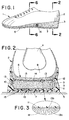
- FIG. 1 is a perspective view of a shoe incorporating a shock absorbing cushion constructed in accordance with the teachings of this invention;
- FIG. 2 is a sectional view taken along line 2-2 of FIG. 1;
- FIG. 3 is an exploded view of a section of FIG. 2 showing details of the invention;
- FIGS. 4A-4F are schematics of the shock absorbing cushion in a variety of compression modes;
- FIGS. 5A-5E are examples of alternative filament interfaces which accomplish the purpose of the invention;
- FIG. 6 is a sectional view taken along line 6-6 of the shoe of FIG. 1;
- FIG. 7 is a perspective topographic view of the cushion of FIGS. 1, 2, 3, and 6;
- FIG. 8 is cross section taken along line 8-8 of FIG. 7;
- FIG. 9 is a cross-section taken along line 9-9 of FIG. 7; and,
- FIG. 10 is a pictorial graph representing the generalized load deflection characteristics of the compression member alone; the support of the contained fluid alone; and the overall combined characteristics of the components working in unison.
- Reference will now be made in detail to the present preferred embodiment of the invention, examples of which are illustrated in the accompanying drawings.
- While the invention will be described in connection with a preferred embodiment, it will be understood that it is not intended to limit the invention to that embodiment. On the contrary, it is intended to cover all alternatives, modifications, and equivalents as may be included within the spirit and scope of the invention defined by the appended claims.
- Referring now to FIGS. 1 and 2, shoe 1 is comprised of an upper 2 constructed of leather, vinyl, nylon, or any other fabric or material utilized in the art, secured to a
mid-sole 3. Mid-sole 3 is secured to an out-sole 5 having studs or otherground engaging elements 7 for traction purposes. Of course,mid-sole 3 and out-sole 5 can be formed as a single element if desired. The shock absorbing cushion of the subject invention is contained inmid-sole 3, withinchamber 9. - Referring particularly to FIG. 2, it can be seen that the heel portion of the foot, comprised of
calcaneus 4 andfat pad 8, rest onsock liner 6 within upper 2. Underlying the foot, withinchamber 9 ofmid-sole 3, is inventiveshock absorbing cushion 10.Cushion 10 is comprised of anelastomeric barrier material 11 hermetically sealed to enclose a fluid (not shown). Also enclosed withinbarrier material 11 with the fluid iscompressible insert 12.Compressible insert 12 may be reinforced with embeddedfilaments 13 which also secure thebarrier material 11 tocompressible insert 12. As best seen in the enlarged view FIG. 3,filaments 13 have afirst portion 13a embedded incompressible insert 12 and asecond portion 13b embedded inbarrier material 11. - Contemplated within the scope of this invention are shock absorbing cushions filled with one or more compressible fluids. A preferred fluid is a gas comprised of inert non-polar large molecules, alone or in combination with air. These devices can be self-inflating via diffusion pumping or mechanically inflated by means of a pump or pressure source in combination with a suitable valving arrangement. For example,
midsole 3 can optionally be provided with valve(s) 16, in sealed communication with theshock absorbing cushion 10. - Gasses which have been found particularly suitable include the following: hexafluoroethane; sulfur hexafluoride; perfluoropropane; perfluorobutane; perfluoropentane; perfluorohexane; perfluoroheptane; octafluorocylcobutane; perfluorocyclobutane; hexafluoropropylene; tetrafluoromethane; monochloropentafluoroethane; 1,2-dichlorotetrafluoroethane; 1,1,2-trichloro-1,2,2-trifluoroethane; chlorotrifluoroethylene; bromotrifluoromethane; and, monochlorotrifluoromethane. Two preferred gasses within this group for use in the members are hexafluoroethane and sulfurhexafluoride in combination with nitrogen. These gases are identified in U.S. patents 4,340,626; 4,936,029; and 5,042,176 as "captive" gases which in combination with gases normally in the atmosphere surrounding the device that diffuse through the semi-permeable barrier film, i.e. "mobile" gases, pressurize the unit.
- Also considered as suitable fluids with which to fill the barrier material are incompressible fluids such as water, semi-gel liquids, oils, grease, soft or liquid wax, glycerine, soft soap, silicones, rheopexic fluids, thixotropic fluids, and corn syrups which exemplify but do not limit the types of acceptable incompressible liquids. A preferred incompressible liquid has a viscosity between 50 and 3000 centistokes, is non-toxic, is odorless, and is resistant to freezing at temperatures to which footwear is typically exposed.
- The flexible barrier member is preferably comprised of elastomeric materials selected from: polyurethane, polyester elastomer, fluoroelastomer, chlorinated polyethylene, polyvinyl chloride, chlorosulfonated polyethylene, polyethylene/ethylene vinyl acetate copolymer, neoprene, butadiene acrylonitrile rubber, butadiene styrene rubber, ethylene propylene polymer, natural rubber, high strength silicone rubber, low density polyethylene, adduct rubber, sulfide rubber, methyl rubber, vulcanizable rubber, polyvinyl alcohol and thermoplastic rubber. Polyurethane is a particularly preferred material for construction of the barrier. The barrier material may also be comprised of crystallographic diffusion controlling materials as defined in U.S. patents 4,936,029 and 5,042,176.
-
Compressible insert 12 may be comprised of any padding material used in the cushioning and footwear art which provides support to both compressive and tensile forces, such as cotton, rubber, foam, horsehair, plastic mesh, etc. Preferably the compressible member is comprised of an at least partially open cell, flexible foam. Polyurethane or ethylene-vinyl acetate foams are preferred. However, any flexible, elastomeric foam common to those skilled in the cushioning and footwear art is suitable. - The cushioning devices, in particular, the fluid filling, flexible barrier materials and general cushion design (i.e. shape, number of chambers, position in a shoe, etc.) may be guided by the teachings in U.S. Patent Nos. 3,005,272; 3,685,176; 3,760,056; 4,183,156; 4,217,705; 4,219,945; 4,271,706; 4,287,250; 4,297,797; 4,340,626; 4,370,754; 4,471,538; 4,486,901; 4,506,460; 4,724,627; 4,779,359; 4,817,304; 4,829,682; 4,864,737; 4,864,738; 4,874,640; 4,906,502; 4,936,029; 5,036,603; 5,042,176; 5,083,361; 5,097,607; 5,155,927; 5,228,217; 5,235,715; 5,245,766; 5,283,963; 5,315,769; and 5,422,185 each of which is herein incorporated by reference.
- As described in these patents, the cushion of the subject invention can form a component of a footwear product in the heel portion, the metatarsal region, the arch of the foot region, any combination of these, or any location in which foot and/or other body part cushioning is desired by one skilled in the art.
- The preferred filament material joining the
flexible barrier material 11 tocompressible member 12 is comprised of polyesters, polyethylene terephthalate, polyamides, nylons, kevlar fiberglass, carbon, glass, silk, cotton, wool, urethane, aramide, dacron, cellulose, rayon, copra, acetate, polyvinyl alcohol, polyacrylics, and mixtures thereof. Of course, any sufficiently strong material which is compatible with the compressible insert and the barrier material is acceptable for use in forming the filaments. - In addition, even materials which are not compatible can be treated with a sizing compound or coupling agent to improve compatibility. Furthermore, as indicated above, the joining material is not limited to filament-like compounds. For example, it is envisioned that the "filaments" can be a fabric texturized to have tendrils, fibers or even loops extending from both facing surfaces thereof. Included within fabrics are woven and nonwoven mats having fibers, tendrils, etc. extending from the surface.
- Preferably, the discrete filaments have a denier per filament of between about 1 and 20 and a length sufficient to allow a first portion to embed in the flexible barrier material and a second portion to embed in the compressible insert. In particular, a preferred fiber reinforced interface will exhibit sufficient tensile strength to provide a separation or peel strength between the barrier layer and compressible insert of at least 5 lb's per linear inch. A preferred embodiment would have a peel strength of at least 13 lbs. per linear inch.
- The construction of a product or device utilizing the inventive cushion is particularly facilitated by the ability of the cushion to be constructed with custom shaped or contoured surfaces. For example, the cross-section of the foam insert in FIG. 2 demonstrates relatively flat top 14 and bottom 15 surfaces. However, and as demonstrated in FIGS. 6 through 9, the foam insert and the corresponding elastomeric flexible barrier material applied thereto can be formed with a contoured surface.
- Referring now to FIG. 6, the
shock absorbing cushion 110 is constructed to conform to the arch 114 of the foot by makingcompressible insert 112 thicker in that region 114. Chopped, orientated filaments or roving are shown properly disbursed in the foam. Accordingly, an extremely comfortable and highly efficient cushion is provided. - This tailoring of the surface is readily demonstrated in FIGS. 7-9. Particularly, it can be seen that the
cushion 210 includes a raisedportion 211 under the arch of the foot, the metatarsal arch of thefoot region 213, and the in the center of the heel for extra cushioning atheel strike 214. The sections 8-8 and 9-9 correspond to the figures; 8 (metatarsal arch) and 9 (heel area). - Referring now to FIGS. 4A-4F, which are enlarged for clarity, the excellent cushioning efficiencies of the inventive cushion are demonstrated. FIGS. 4A-F demonstrates the ability of the fluid filled portion of the cushioning insert to provide a comfortable feel, i.e. riding on air -- when compressible fluids are utilized --which upon exertion of force provides an exceptional and uniquely beneficial absorbance, distribution, storage, and return of energy. In addition, the compressible insert provides additional cushioned support and assurance against bottoming-out of the device. The
filament interface 313 is seen joiningcompressible insert 312 toelastomeric barrier envelope 311. - In view A, the foot experiences a "riding-on-air" type of support which provides a high degree of comfort. Particularly, the pressure of the fluid supports the foot and there is very little compression of the device. This is depicted in the graph of Fig. 10, where the letters A-D on the abscissa of the graph refer to corresponding FIGURES 4A thru 4D. View B demonstrates a moderate amount of compression -- for example light running --wherein the
elastomeric material 311 and fluid contained therein is compressed; however, the force is not significant enough to significantly deform the compressible insert 312 (see abscissa "B", FIG. 10). In this state, the compression of the fluid absorbs the majority of the force. View C demonstrates hard running -- wherein a more severe impact is experienced. It can be seen that in addition to compression of the fluid contained inelastomeric material 311, thecompressible insert 312 begins to deform and share in the shock absorbance (abscissa "C", FIG. 10). Referring now to View D, a heavy impact -- for example a jump landing --is demonstrated. In this condition, theelastomeric barrier 311 and fluid contained therein and thecompressible insert 312 have nearly "bottomed out", i.e. fully compressed. In this condition, the compressible insert member supports and cushions the excess loads that would otherwise bottom out the purely fluid/pneumatic cushioning device (abscissa "D", FIG. 10). Accordingly, a great deal of force has been absorbed and distributed to achieve an extended range and degree of cushioning and durability not available in the prior art. In View E, with the load partially removed, the absorbed force is returned to the foot aselastomeric barrier 311 is forced outward by the pressurized fluid. This action, in combination with the expansion of thecompressible insert 312 to its original form during mid-foot and toe-off phases, returns a great deal of the otherwise wasted cushioned heel strike energy to the foot and body and ultimately returns the cushion to its original form (View F). - A variety of methods are envisioned for constructing the device. For example, a woven or nonwoven fabric can be texturized, flannelized or the equivalent, on each side to provide exposed filaments or loops on the surfaces of the fabric. These exposed portions can then be bonded to selected portions of the external surface of the compressible insert. For example, a foam can be chemically or thermally partially cured to achieve a solid center and a tacky, penetrable surface. The texturized fabric, trimmed in advance or after attachment, is layed on and pressed into the penetrable surface. Final curing of the foam embeds the filaments therein, creating a secure bond. The multitude of high tensile strength filaments of the fabric penetrate the surface layers of the compression member and simultaneously overlap and bond to the filaments comprising the surface layer of the compressible insert. Similarly, the filaments internal to the compressible insert are disbursed in an overlapping manner and bond to one another throughout the cross-section. Accordingly, bonding of filament to filament as they overlap one another is achieved, providing the compressible member with excellent tensile and compressive strength and bonding to the elastomeric envelope.
- Care should be taken to avoid immersion and saturation of the exposed side of the fabric so as to preserve and maintain exposure of the filaments destined for embedding in, or secured attachment to the elastomeric barrier material. The elastomeric material, in sheets or blow molded or otherwise pre-formed, are placed on the top and bottom surfaces of the fabric coated foam insert and secured to the filaments via flame treatment, ultrasound, I.R., microwave or RF heating or other method common to those skilled in the art, to at least partially melt the surface facing the filaments. Preferably, only the facing surface of the elastomeric sheet is melted to a controlled depth, allowing the exposed filaments to only partially penetrate the elastomeric member and embed therein. Only partial penetration is desired because a filament extending through the entirety of the barrier layer provides a "leak path" for fluid escape and eventual cushion failure.
- Thereafter, the elastomeric barrier envelope comprising at least one compression member is sealed at the perimeter, for example by RF welding. A fluid may then be transported into the sealed barrier envelope via activated diffusion, chamber to chamber transport, or injected mechanically by a needle or a valve --
item 16 of FIG. 1-- to complete the cushion. - Alternatively, the fabric can be replaced with a chopped or woven roving sprayed or otherwise flocked or eletrostatically uniformly disbursed and positioned onto the semi-cured surface of the compressible insert.
- Likewise, the process can be reversed wherein the elastomeric envelope is prepared and a chopped roving or fabric is embedded onto its interior surface. Thereafter, a compressible insert is cured within the elastomeric envelope and allowed to embed the filaments. This method is particularly desirable because chopped filament roving can be readily secured to an elastomeric sheet or blow molded envelope when it is exposed to a heated platen or heated air, respectively. Moreover, the exterior surface will cure first and allow partial filament penetration.
- Alternatively, when a compressible insert having filament reinforcement is utilized, the compressible insert can be constructed with filaments which extend beyond the outer walls of the compressible insert. Preferably, the filaments extending from the surface will be trimmed to the desired length to facilitate application of the elastomeric barrier material and embedding therein.
- Alternatively, it is envisioned that a filament reinforced compressible insert can be designed with finger-like or teat-like projections, with or without containing filament reinforcement. When the elastomer barrier material is applied thereto, the fingers and inherently the filaments become embedded in the elastomeric barrier material.
- As will be apparent to those skilled in the art, there are a vast array of mechanisms and techniques by which a filament interface between the compressible insert and the flexible barrier envelope can be achieved. The important factor is embedding first and second portions of a sufficient length and quantity of filaments to achieve a peel strength, preferably, at least 5 lbs. per linear inch, more preferably at least 13 lbs. per linear inch. Preferably, there are at least 1000 filaments per square inch in the regions of attachment.
- Of course, compressible inserts comprised of woven, twisted, sewn or matted fibers or filaments, for example sewn cotton fiber pads, can simply be texturized to expose the desired amount of filaments which can be embedded in the elastomeric barrier envelope. In this context, the filaments are "embedded" and secured in the compressible insert directly as a result of their woven or matted construction.
- Examples of filament interface techniques, meant to demonstrate but not limit the invention, are provided in FIGS. 3 and 5A-E. In FIG. 3, the exposed ends of
reinforcement filaments 13 are embedded inbarrier member 11. Referring now to FIG. 5A, a plurality of choppedroving filaments 413 have been embedded in bothelastomeric barrier member 411 and incompressible insert 412. In FIG. 5B,compressible insert 512 includes finger likeprotrusions 514, which contain at least some ends of the reinforcingfilaments 513. Since theprotrusions 514 are embedded inelastomeric barrier member 511, thefilaments 513 become embedded and secured therein as well. In FIGS. 5C and 5D, fabrics are demonstrated as the filament interface material. In FIG. 5C, afabric 610 having a plurality ofloops 613 provides the interface betweencompressible insert 612 andelastomeric barrier 611. In FIG. 5D, atexturized fabric 710 having a plurality of exposed fibrils orfilaments 713 secureselastomeric barrier layer 711 to thecompressible insert 712. In FIG. 5E, teat-like protrusions 813 form the internal surface ofelastomeric barrier layer 811. These protrusions extend intocompressible insert 812, contacting and securinglayer 811 tofibers 814. - Finally, it is noted that the filament junction of the compressible insert and elastomeric barrier material can be supplemental with adhesive or a coupling layer attachment.
- Thus, it is apparent that there has been provided, in accordance with the invention, a cushioning device for products and objects which encounter impact forces that fully satisfies the objects, aims, and advantages set forth above. While the invention has been described in conjunction with specific embodiments thereof, it is evident that many alternatives, modifications, and variations would be apparent to those skilled in the art in light of the foregoing description. Accordingly, it is intended to embrace all such alternatives, modifications, and variations as fall within the spirit and broad scope of the appended claims.
- Said compressible member may be shaped to conform to a human foot and may comprise urethane foam between two opposed substantially planar surfaces. Said flexible barrier material may comprise urethane. The cushion further may comprise at least 1000 embedded filaments per square inch.
- Said filaments may comprise a material selected from the group consisting of polyester, polyamide, nylon, fiberglass, carbon, polyethylene terephthalate, silk, cotton, wool, urethane, aramide, dacron, cellulose, rayon, copra, acetate, polyvinyl alcohol, polyacrylic, and mixtures thereof. Said filaments may have a denier per filament of between about 1 and 20 and preferably a tensile strength of from about 2 to 10 grams per denier. The separation strength of said barrier material from said compressible member may lie between about 5 to 40 pounds per linear inch. Further an adhesive may be provided securing said compressible member to said barrier material. Further a coupling layer may be disposed between said compressible member and said barrier material.
- A fluid impervious material surrounding said foam core as an envelope may be a semi-permeable elastomeric material, wherein said foam is an open cell foam, or a partially open cell foam. Said fluid may be compressible with said envelope having a gage pressure of at least 0 pounds per square inch. Alternatively, said fluid may be incompressible.
- Said filaments may be components of a fabric.
- An article of footwear according to the invention may comprise an envelope to house a foot and a sole portion comprised of an elastomeric material that is substantially impervious to a large molecule, non-polar gas, and is permeable to air in the shape of a cushion, said cushion containing a compressible insert and said gas, a plurality of filaments connecting said elastomeric material and said compressible insert.
- A shock absorbing cushioning device suitable for products, objects and footwear which is comprised of a compressible insert encapsulated within an elastomeric barrier member. The elastomeric barrier member is secured to the compressible insert by a plurality of tensile members having a first portion embedded in the elastomeric material and a second portion embedded in the compressible insert. The elastomeric member is also filled with a fluid, preferably a compressible gas.
Claims (10)
- A cushioning device comprised of a flexible barrier material defining at least one sealed chamber, a compressible member and a liquid contained within said chamber, said compressible member being secured to said barrier material by a plurality of filaments having a first portion embedded in said barrier material and a second portion embedded in said compressible member.
- The cushion of claim 1 wherein said compressible member is shaped to conform to a human body.
- The cushion of claim 1 wherein said compressible member is comprised of foam.
- The cushion of claim 1 wherein said fluid is compressible.
- The cushion of claim 4 wherein said chamber has a gage pressure equal to or greater than 0.
- The cushion of claim 1 wherein said fluid is incompressible.
- The cushion of claim 4 wherein said fluid is a gas selected from the group consisting of air, nitrogen, hexafluoroethane, sulfur hexafluoride, hexafluoroethane; sulfur hexafluoride; perfluoropropane; perfluorobutane; perfluoropentane; perfluorohexane; perfluoroheptane; octafluorocylcobutane; perfluorocyclobutane; hexafluoropropylene; tetrafluoromethane; monochloropentafluoroethane; 1,2-dichlorotetra-fluoroethane; 1,1,2-trichloro-1,2,2-trifluoroethane; chlorotrifluoroethylene; bromotrifluoromethane; monochlorotrifluoromethane; and mixtures thereof.
- The cushion of claim 6 wherein the fluid is selected from the group consisting of water, semi-gel liquids, oil, grease, soft or liquid wax, glycerine, soaps, silicone, corn syrup, rheopexic liquids, thixotropic liquids; and mixtures thereof.
- The cushion of claim 1 wherein said flexible barrier material is comprised of urethane.
- A cushioning member for an article of footwear comprised of a flexible foam core shaped to protect at least a portion of a footsole, said foam core surrounded by an envelope comprised of a material which is impervious to at least a selected fluid, a plurality of filaments having a first portion secured to said fluid impervious material and a second portion secured to said foam core, and a fluid contained within said envelope.
Applications Claiming Priority (2)
| Application Number | Priority Date | Filing Date | Title |
|---|---|---|---|
| US08/516,942 US5741568A (en) | 1995-08-18 | 1995-08-18 | Shock absorbing cushion |
| US516942 | 1995-08-18 |
Publications (3)
| Publication Number | Publication Date |
|---|---|
| EP0759276A2 true EP0759276A2 (en) | 1997-02-26 |
| EP0759276A3 EP0759276A3 (en) | 1997-12-17 |
| EP0759276B1 EP0759276B1 (en) | 2002-11-06 |
Family
ID=24057706
Family Applications (1)
| Application Number | Title | Priority Date | Filing Date |
|---|---|---|---|
| EP96113194A Expired - Lifetime EP0759276B1 (en) | 1995-08-18 | 1996-08-16 | Improved shock absorbing cushion |
Country Status (10)
| Country | Link |
|---|---|
| US (2) | US5741568A (en) |
| EP (1) | EP0759276B1 (en) |
| KR (1) | KR100230702B1 (en) |
| CN (1) | CN1121164C (en) |
| AR (1) | AR003260A1 (en) |
| CA (1) | CA2182753C (en) |
| DE (2) | DE69624640T2 (en) |
| ES (1) | ES2100145T3 (en) |
| MY (1) | MY123059A (en) |
| TW (1) | TW326389B (en) |
Cited By (3)
| Publication number | Priority date | Publication date | Assignee | Title |
|---|---|---|---|---|
| WO2002056718A1 (en) * | 2001-01-17 | 2002-07-25 | Spenco Medical Corporation | Insole with cushioning areas and adjustable arch support |
| WO2013022850A1 (en) * | 2011-08-05 | 2013-02-14 | Newton Running Company, Inc. | Shoe soles for shock absorption and energy return |
| US20220341483A1 (en) * | 2021-04-26 | 2022-10-27 | Geoff McCue | Shock absorbing structure |
Families Citing this family (196)
| Publication number | Priority date | Publication date | Assignee | Title |
|---|---|---|---|---|
| USD953709S1 (en) | 1985-08-29 | 2022-06-07 | Puma SE | Shoe |
| USD855953S1 (en) | 2017-09-14 | 2019-08-13 | Puma SE | Shoe sole element |
| US6453577B1 (en) | 1996-02-09 | 2002-09-24 | Reebok International Ltd. | Support and cushioning system for an article of footwear |
| US8025964B2 (en) * | 1994-06-03 | 2011-09-27 | Tempur World, Llc | Laminated visco-elastic support |
| GB2290256B (en) | 1994-06-03 | 1997-10-29 | Fagerdala World Foams Ab | Laminated supports |
| US6939502B2 (en) * | 1995-08-02 | 2005-09-06 | Robert M. Lyden | Method of making custom insoles and point of purchase display |
| US6016637A (en) * | 1997-06-12 | 2000-01-25 | Kelley Company, Inc. | Dock seal and method of producing the same |
| US5993585A (en) * | 1998-01-09 | 1999-11-30 | Nike, Inc. | Resilient bladder for use in footwear and method of making the bladder |
| DE29804991U1 (en) * | 1998-03-19 | 1998-06-10 | Alsa Gmbh | sandal |
| US5996253A (en) * | 1998-08-31 | 1999-12-07 | Spector; Donald | Adjustable innersole for athletic shoe |
| US20050166302A1 (en) * | 1998-09-03 | 2005-08-04 | Mjd Innovations, L.L.C. | Non-resiliency body-contact protective helmet interface structure |
| AU5909299A (en) * | 1998-09-03 | 2000-03-27 | Mike Dennis | Body-contact cushioning interface structure |
| US7334350B2 (en) * | 1999-03-16 | 2008-02-26 | Anatomic Research, Inc | Removable rounded midsole structures and chambers with computer processor-controlled variable pressure |
| US6574886B1 (en) * | 1999-03-31 | 2003-06-10 | H.H. Brown Shoe Company, Inc. | Footwear and its method of construction |
| US6354020B1 (en) | 1999-09-16 | 2002-03-12 | Reebok International Ltd. | Support and cushioning system for an article of footwear |
| US6457262B1 (en) | 2000-03-16 | 2002-10-01 | Nike, Inc. | Article of footwear with a motion control device |
| US6385864B1 (en) | 2000-03-16 | 2002-05-14 | Nike, Inc. | Footwear bladder with controlled flex tensile member |
| US6571490B2 (en) | 2000-03-16 | 2003-06-03 | Nike, Inc. | Bladder with multi-stage regionalized cushioning |
| US6374514B1 (en) | 2000-03-16 | 2002-04-23 | Nike, Inc. | Footwear having a bladder with support members |
| US6402879B1 (en) | 2000-03-16 | 2002-06-11 | Nike, Inc. | Method of making bladder with inverted edge seam |
| US8574146B2 (en) * | 2000-04-14 | 2013-11-05 | Attenuex Technologies, Inc. | Implant with high vapor pressure medium |
| US10327880B2 (en) | 2000-04-14 | 2019-06-25 | Attenuex Technologies, Inc. | Attenuation device for use in an anatomical structure |
| US6988983B2 (en) * | 2000-04-14 | 2006-01-24 | Solace Therapeutics, Inc. | Implantable self-inflating attenuation device |
| US6682473B1 (en) * | 2000-04-14 | 2004-01-27 | Solace Therapeutics, Inc. | Devices and methods for attenuation of pressure waves in the body |
| US7374532B2 (en) * | 2000-04-14 | 2008-05-20 | Attenuex Technologies, Inc. | High vapor pressure attenuation device |
| WO2002031377A2 (en) | 2000-10-12 | 2002-04-18 | Skydex Technologies, Inc. | Cushioning structure for floor and ground surfaces |
| CA2432999A1 (en) * | 2000-12-22 | 2002-07-04 | Avery Dennison Corporation | Conformable films and articles made therefrom |
| DE10112821B9 (en) * | 2001-03-16 | 2004-10-28 | Adidas International Marketing B.V. | Sole and shoe |
| WO2002078478A1 (en) * | 2001-04-02 | 2002-10-10 | Flexin Athletics, Inc. | Athletic shoe with ankle guards |
| US7107704B2 (en) * | 2001-04-04 | 2006-09-19 | Mjd Innovations, L.L.C. | Cushioning shoe insole |
| KR20010068014A (en) * | 2001-04-14 | 2001-07-13 | 정영덕 | airbag for shoes plate and its processing method |
| US6591456B2 (en) * | 2001-07-09 | 2003-07-15 | Bic Corporation | Cushioning device |
| US7577583B2 (en) * | 2001-08-09 | 2009-08-18 | Acushnet Company | Computerized article customization system and method for use thereof |
| US6782640B2 (en) | 2001-09-12 | 2004-08-31 | Craig D. Westin | Custom conformable device |
| US7131218B2 (en) * | 2004-02-23 | 2006-11-07 | Nike, Inc. | Fluid-filled bladder incorporating a foam tensile member |
| US20050167029A1 (en) * | 2001-11-26 | 2005-08-04 | Nike, Inc. | Method of thermoforming a fluid-filled bladder |
| US20030115774A1 (en) * | 2001-12-21 | 2003-06-26 | The Board Of Trustees Of The University Of Illinois | Foot strike energy absorption method for shoes |
| GB0130834D0 (en) * | 2001-12-22 | 2002-02-06 | Design Blue Ltd | Energy absorbing material |
| DE10212862C1 (en) * | 2002-03-22 | 2003-10-30 | Adidas Int Marketing Bv | Sole and shoe |
| US7426792B2 (en) * | 2002-05-09 | 2008-09-23 | Nike, Inc. | Footwear sole component with an insert |
| US6796056B2 (en) * | 2002-05-09 | 2004-09-28 | Nike, Inc. | Footwear sole component with a single sealed chamber |
| US6812375B2 (en) * | 2002-06-19 | 2004-11-02 | Michael R. Dennis | Pressure-evenizing low-rebound wound dressing |
| US20040039106A1 (en) * | 2002-06-27 | 2004-02-26 | Man Aren Joost De | Conformable calendered films and articles made therefrom |
| DE102005006267B3 (en) | 2005-02-11 | 2006-03-16 | Adidas International Marketing B.V. | Shoe sole e.g. for sport shoe, has heel which has bowl or edge having form corresponding to heel of foot and underneath bowl and or edge of heel side panels which are connected to separate rear side panel |
| US7401419B2 (en) | 2002-07-31 | 2008-07-22 | Adidas International Marketing B.V, | Structural element for a shoe sole |
| US6962010B2 (en) | 2002-10-02 | 2005-11-08 | Footstar Corporation | Dress shoe with improved heel counter |
| JP4814634B2 (en) * | 2002-10-03 | 2011-11-16 | ソレイス セラピューティクス、インコーポレイテッド | Implantable pressure damping device |
| US7341776B1 (en) | 2002-10-03 | 2008-03-11 | Milliren Charles M | Protective foam with skin |
| US20040139531A1 (en) * | 2002-12-06 | 2004-07-22 | Moore Dan T. | Custom fitted helmet and method of making the same |
| US20040159015A1 (en) * | 2003-02-14 | 2004-08-19 | Dennis Michael R. | Shoe insole with layered partial perforation |
| US7396574B2 (en) | 2003-05-28 | 2008-07-08 | Robert C. Bogert | Self-inflating cushion and footwear including same |
| GB0314824D0 (en) * | 2003-06-25 | 2003-07-30 | Design Blue Ltd | Energy absorbing material |
| US7080467B2 (en) * | 2003-06-27 | 2006-07-25 | Reebok International Ltd. | Cushioning sole for an article of footwear |
| US7000335B2 (en) * | 2003-07-16 | 2006-02-21 | Nike, Inc. | Footwear with a sole structure incorporating a lobed fluid-filled chamber |
| US7707744B2 (en) * | 2003-07-16 | 2010-05-04 | Nike, Inc. | Footwear with a sole structure incorporating a lobed fluid-filled chamber |
| US7128796B2 (en) * | 2003-07-16 | 2006-10-31 | Nike, Inc. | Footwear with a sole structure incorporating a lobed fluid-filled chamber |
| US7707745B2 (en) | 2003-07-16 | 2010-05-04 | Nike, Inc. | Footwear with a sole structure incorporating a lobed fluid-filled chamber |
| US6931764B2 (en) * | 2003-08-04 | 2005-08-23 | Nike, Inc. | Footwear sole structure incorporating a cushioning component |
| US7070845B2 (en) * | 2003-08-18 | 2006-07-04 | Nike, Inc. | Fluid-filled bladder for an article of footwear |
| US7155765B2 (en) * | 2003-10-14 | 2007-01-02 | Tempur World, Llc | Pillow top for a cushion |
| US20050086838A1 (en) * | 2003-10-24 | 2005-04-28 | Khantzis Carlos A. | Shoe sole to improve walking, sensory response of the toes, and help develop leg muscles |
| US7353625B2 (en) * | 2003-11-03 | 2008-04-08 | Reebok International, Ltd. | Resilient cushioning device for the heel portion of a sole |
| US7448522B2 (en) * | 2003-11-11 | 2008-11-11 | Nike, Inc. | Fluid-filled bladder for use with strap |
| US7086179B2 (en) * | 2003-12-23 | 2006-08-08 | Nike, Inc. | Article of footwear having a fluid-filled bladder with a reinforcing structure |
| US7562469B2 (en) * | 2003-12-23 | 2009-07-21 | Nike, Inc. | Footwear with fluid-filled bladder and a reinforcing structure |
| US7086180B2 (en) * | 2003-12-23 | 2006-08-08 | Nike, Inc. | Article of footwear having a fluid-filled bladder with a reinforcing structure |
| US7100310B2 (en) * | 2003-12-23 | 2006-09-05 | Nike, Inc. | Article of footwear having a fluid-filled bladder with a reinforcing structure |
| US7156787B2 (en) * | 2003-12-23 | 2007-01-02 | Nike, Inc. | Inflatable structure and method of manufacture |
| US7141131B2 (en) * | 2003-12-23 | 2006-11-28 | Nike, Inc. | Method of making article of footwear having a fluid-filled bladder with a reinforcing structure |
| US7556846B2 (en) * | 2003-12-23 | 2009-07-07 | Nike, Inc. | Fluid-filled bladder with a reinforcing structure |
| US20070063368A1 (en) * | 2004-02-23 | 2007-03-22 | Nike, Inc. | Fluid-filled bladder incorporating a foam tensile member |
| US7383648B1 (en) * | 2004-02-23 | 2008-06-10 | Reebok International Ltd. | Inflatable support system for an article of footwear |
| US20050255307A1 (en) * | 2004-05-11 | 2005-11-17 | Mjd Innovations, L.L.C. | Body-contact interface structure with neutral internal adhesive interface |
| US7200955B2 (en) * | 2004-06-04 | 2007-04-10 | Nike, Inc. | Article of footwear incorporating a sole structure with compressible inserts |
| WO2006022678A2 (en) * | 2004-08-03 | 2006-03-02 | New Balance Athletic Shoe, Inc. | Insert for an article of footwear |
| US8039078B2 (en) * | 2004-08-26 | 2011-10-18 | Intellectual Property Holdings, Llc | Energy-absorbing pads |
| US7468334B2 (en) * | 2004-10-04 | 2008-12-23 | Highland Industries, Inc. | Silicone vulcanizate coated fabric |
| US20080066342A1 (en) * | 2004-11-12 | 2008-03-20 | Park Jang W | Shock-Absorbing Device for Shoes |
| US7802378B2 (en) * | 2005-02-14 | 2010-09-28 | New Balance Athletic Shoe, Inc. | Insert for article of footwear and method for producing the insert |
| DE102005015863A1 (en) * | 2005-04-07 | 2006-10-12 | Stumpf, Jürgen | footbed |
| US7513066B2 (en) | 2005-04-14 | 2009-04-07 | Nike, Inc. | Fluid-filled bladder for footwear and other applications |
| US7904971B2 (en) * | 2005-05-19 | 2011-03-15 | Mine Safety Appliances Company | Protective padding and protective padding systems |
| US7622014B2 (en) | 2005-07-01 | 2009-11-24 | Reebok International Ltd. | Method for manufacturing inflatable footwear or bladders for use in inflatable articles |
| WO2007038476A2 (en) | 2005-09-26 | 2007-04-05 | Atteneux Technologies, Inc. | Pressure attenuation device |
| US7533477B2 (en) | 2005-10-03 | 2009-05-19 | Nike, Inc. | Article of footwear with a sole structure having fluid-filled support elements |
| DE102006015649B4 (en) | 2006-04-04 | 2008-02-28 | Adidas International Marketing B.V. | shoe |
| US7757409B2 (en) * | 2006-04-27 | 2010-07-20 | The Rockport Company, Llc | Cushioning member |
| US8414275B1 (en) | 2007-01-11 | 2013-04-09 | Reebok International Limited | Pump and valve combination for an article of footwear incorporating an inflatable bladder |
| US7810255B2 (en) * | 2007-02-06 | 2010-10-12 | Nike, Inc. | Interlocking fluid-filled chambers for an article of footwear |
| US8276296B2 (en) * | 2007-02-12 | 2012-10-02 | Pierre-Andre Senizergues | Dynamically moderated shock attenuation system |
| US8359770B2 (en) | 2007-02-12 | 2013-01-29 | Pierre Senizergues | Dynamically moderated shock attenuation system for apparel |
| US7788826B2 (en) * | 2007-02-12 | 2010-09-07 | Pierre Senizgues | Dynamically moderated shock attenuation system for footwear |
| US8302330B2 (en) * | 2007-04-20 | 2012-11-06 | Mark Doran | Footwear and systems and methods for merchandising footwear |
| US7950169B2 (en) | 2007-05-10 | 2011-05-31 | Nike, Inc. | Contoured fluid-filled chamber |
| US7941941B2 (en) * | 2007-07-13 | 2011-05-17 | Nike, Inc. | Article of footwear incorporating foam-filled elements and methods for manufacturing the foam-filled elements |
| US7591919B2 (en) | 2007-08-13 | 2009-09-22 | Nike, Inc. | Fluid-filled chambers with foam tensile members and methods for manufacturing the chambers |
| US7588654B2 (en) | 2007-08-13 | 2009-09-15 | Nike, Inc. | Fluid-filled chambers with foam tensile members and methods for manufacturing the chambers |
| US8863408B2 (en) * | 2007-12-17 | 2014-10-21 | Nike, Inc. | Article of footwear having a sole structure with a fluid-filled chamber |
| US8241450B2 (en) | 2007-12-17 | 2012-08-14 | Nike, Inc. | Method for inflating a fluid-filled chamber |
| US20090152774A1 (en) * | 2007-12-17 | 2009-06-18 | Nike, Inc. | Method For Molding A Fluid-Filled Structure |
| US8178022B2 (en) * | 2007-12-17 | 2012-05-15 | Nike, Inc. | Method of manufacturing an article of footwear with a fluid-filled chamber |
| US20100269246A1 (en) * | 2007-12-24 | 2010-10-28 | Nutricom Ltd. | Safety helmet adapted for quick and easy emergency removal |
| US8572867B2 (en) | 2008-01-16 | 2013-11-05 | Nike, Inc. | Fluid-filled chamber with a reinforcing element |
| US8341857B2 (en) | 2008-01-16 | 2013-01-01 | Nike, Inc. | Fluid-filled chamber with a reinforced surface |
| US8241451B2 (en) | 2008-05-20 | 2012-08-14 | Nike, Inc. | Contoured fluid-filled chamber with a tensile member |
| US8151486B2 (en) * | 2008-05-20 | 2012-04-10 | Nike, Inc. | Fluid-filled chamber with a textile tensile member |
| US20100011540A1 (en) * | 2008-07-17 | 2010-01-21 | Shiow-Hui Chen | Pliable handle |
| US7862490B2 (en) * | 2008-07-28 | 2011-01-04 | Sean Glynn | Exercise machine force application apparatus |
| MX2011001920A (en) * | 2008-08-24 | 2011-03-30 | Tetra Laval Holdings & Finance | Packing/filling machine. |
| US20100083423A1 (en) * | 2008-10-06 | 2010-04-08 | Mjd Innovations, L.L.C. | Helmet liner with improved, seam-position-enhanced, rear-sector load management |
| US8943709B2 (en) * | 2008-11-06 | 2015-02-03 | Nike, Inc. | Article of footwear with support columns having fluid-filled bladders |
| US8087187B2 (en) * | 2008-11-06 | 2012-01-03 | Nike, Inc. | Article of footwear with support assemblies |
| US8196316B2 (en) * | 2009-01-26 | 2012-06-12 | Nike, Inc. | Article of footwear with two part midsole assembly |
| US8244499B2 (en) * | 2009-01-30 | 2012-08-14 | Aquifer Resource Management, Inc. | Methods and systems for managing aquifer operation |
| US8209885B2 (en) | 2009-05-11 | 2012-07-03 | Brooks Sports, Inc. | Shoe assembly with non-linear viscous liquid |
| US8650775B2 (en) | 2009-06-25 | 2014-02-18 | Nike, Inc. | Article of footwear having a sole structure with perimeter and central elements |
| US8701294B2 (en) * | 2009-09-13 | 2014-04-22 | Acme United Corporation | Cutting implement with interchangeable/replaceable blades |
| US20110099845A1 (en) * | 2009-11-03 | 2011-05-05 | Miller Michael J | Customized footwear and methods for manufacturing |
| US9119439B2 (en) | 2009-12-03 | 2015-09-01 | Nike, Inc. | Fluid-filled structure |
| US8479412B2 (en) | 2009-12-03 | 2013-07-09 | Nike, Inc. | Tethered fluid-filled chambers |
| US20110179675A1 (en) * | 2010-01-14 | 2011-07-28 | Miller Michael J | Sport specific footwear insole |
| USD617503S1 (en) | 2010-01-27 | 2010-06-08 | Intellectual Property Holdings, Llc | Helmet pad structure |
| US8991072B2 (en) * | 2010-02-22 | 2015-03-31 | Nike, Inc. | Fluid-filled chamber incorporating a flexible plate |
| US20120304367A1 (en) * | 2010-02-26 | 2012-12-06 | Thl Holding Company, Llc | Protective helmet |
| US8381418B2 (en) | 2010-05-10 | 2013-02-26 | Nike, Inc. | Fluid-filled chambers with tether elements |
| US8464439B2 (en) | 2010-05-12 | 2013-06-18 | Nike, Inc. | Contoured fluid-filled chamber with a tensile member |
| US8470113B2 (en) | 2010-05-12 | 2013-06-25 | Nike, Inc. | Method of manufacturing a contoured fluid-filled chamber with a tensile member |
| US8726424B2 (en) | 2010-06-03 | 2014-05-20 | Intellectual Property Holdings, Llc | Energy management structure |
| US8572786B2 (en) | 2010-10-12 | 2013-11-05 | Reebok International Limited | Method for manufacturing inflatable bladders for use in footwear and other articles of manufacture |
| US9144268B2 (en) | 2010-11-02 | 2015-09-29 | Nike, Inc. | Strand-wound bladder |
| US9161592B2 (en) | 2010-11-02 | 2015-10-20 | Nike, Inc. | Fluid-filled chamber with a stacked tensile member |
| TW201233556A (en) * | 2010-11-24 | 2012-08-16 | Applied Ft Composite Solutions Inc | Composite cushioning material and jigless method for making the same |
| US8869430B2 (en) * | 2011-03-16 | 2014-10-28 | Nike, Inc. | Method of manufacturing a contoured fluid-filled chamber with tensile structures |
| US8857076B2 (en) | 2011-04-06 | 2014-10-14 | Nike, Inc. | Article of footwear with an adaptive fluid system |
| US8813389B2 (en) | 2011-04-06 | 2014-08-26 | Nike, Inc. | Adjustable bladder system for an article of footwear |
| US8844165B2 (en) * | 2011-04-06 | 2014-09-30 | Nike, Inc. | Adjustable bladder system with external valve for an article of footwear |
| US9060564B2 (en) | 2011-04-06 | 2015-06-23 | Nike, Inc. | Adjustable multi-bladder system for an article of footwear |
| US8839530B2 (en) | 2011-04-12 | 2014-09-23 | Nike, Inc. | Method of lasting an article of footwear with a fluid-filled chamber |
| US9516910B2 (en) | 2011-07-01 | 2016-12-13 | Intellectual Property Holdings, Llc | Helmet impact liner system |
| USD679058S1 (en) | 2011-07-01 | 2013-03-26 | Intellectual Property Holdings, Llc | Helmet liner |
| US9056983B2 (en) | 2011-09-09 | 2015-06-16 | Purdue Research Foundation | Dynamic load-absorbing materials and articles |
| USD683079S1 (en) | 2011-10-10 | 2013-05-21 | Intellectual Property Holdings, Llc | Helmet liner |
| JP6001262B2 (en) * | 2011-12-09 | 2016-10-05 | 興和株式会社 | Method for producing shock absorbing sheet excellent in design and shock absorbing sheet |
| CH705996B1 (en) * | 2011-12-29 | 2016-01-15 | Joya Schuhe AG | Shoe and method for producing a shoe. |
| US8747593B2 (en) | 2012-04-10 | 2014-06-10 | Nike, Inc. | Methods for manufacturing fluid-filled chambers incorporating spacer textile materials |
| US9375049B2 (en) | 2012-04-10 | 2016-06-28 | Nike, Inc. | Spacer textile materials and methods for manufacturing the spacer textile materials |
| US9131748B2 (en) | 2012-04-24 | 2015-09-15 | Nike, Inc. | Sole assembly with gas and viscous fluid-filled bladder assembly |
| US9320311B2 (en) | 2012-05-02 | 2016-04-26 | Intellectual Property Holdings, Llc | Helmet impact liner system |
| CN102687933B (en) * | 2012-06-15 | 2015-04-15 | 浙江红蜻蜓鞋业股份有限公司 | Shoe pads capable of adjusting buffering power |
| EP2877064B1 (en) | 2012-07-27 | 2019-05-08 | Tempur-Pedic Management, LLC | Body support cushion having multiple layers of phase change material |
| US8894563B2 (en) | 2012-08-10 | 2014-11-25 | Attenuex Technologies, Inc. | Methods and systems for performing a medical procedure |
| US10631593B2 (en) | 2012-08-21 | 2020-04-28 | Levi J. Patton | Fluid-filled chamber with a stabilization structure |
| US9456658B2 (en) * | 2012-09-20 | 2016-10-04 | Nike, Inc. | Sole structures and articles of footwear having plate moderated fluid-filled bladders and/or foam type impact force attenuation members |
| US9894953B2 (en) | 2012-10-04 | 2018-02-20 | Intellectual Property Holdings, Llc | Helmet retention system |
| US9380832B2 (en) | 2012-12-20 | 2016-07-05 | Nike, Inc. | Article of footwear with fluid-filled chamber lacking an inflation channel and method for making the same |
| US9872535B2 (en) * | 2012-12-20 | 2018-01-23 | Nike, Inc. | Article of footwear with a harness and fluid-filled chamber arrangement |
| US10806214B2 (en) * | 2013-03-08 | 2020-10-20 | Nike, Inc. | Footwear fluid-filled chamber having central tensile feature |
| US9603414B2 (en) | 2013-03-15 | 2017-03-28 | Nike, Inc. | Fluid-filled chamber with a tensile element |
| CN103251173A (en) * | 2013-04-27 | 2013-08-21 | 张东井 | Damping structure with flexible airtight materials wrapping soft foaming materials in sealing mode |
| US9730487B2 (en) * | 2013-07-12 | 2017-08-15 | Nike, Inc. | Contoured fluid-filled chamber |
| US9750302B2 (en) * | 2013-08-13 | 2017-09-05 | Heel-It, Llc | Orthotic insert device |
| USD733972S1 (en) | 2013-09-12 | 2015-07-07 | Intellectual Property Holdings, Llc | Helmet |
| WO2015065902A1 (en) | 2013-10-28 | 2015-05-07 | Intellectual Property Holdings, Llc | Helmet retention system |
| US9320320B1 (en) | 2014-01-10 | 2016-04-26 | Harry A. Shamir | Exercise shoe |
| DE102014003017A1 (en) * | 2014-03-07 | 2015-09-10 | Enquiring Eye GmbH | Footwear with elastic midsole |
| USD793625S1 (en) | 2014-10-23 | 2017-08-01 | Intellectual Property Holdings, Llc | Helmet |
| WO2016081385A1 (en) * | 2014-11-17 | 2016-05-26 | Gill Zora S | Impact absorbing shoe |
| US10248985B2 (en) | 2015-01-16 | 2019-04-02 | Brooks Sports, Inc. | Systems and methods for analyzing lower body movement to recommend footwear |
| TWI645796B (en) * | 2015-02-06 | 2019-01-01 | 亞適足企業有限公司 | Foot stabilizing device |
| US9609909B2 (en) | 2015-04-27 | 2017-04-04 | Bio Foot Pad, Inc. | Bio heel pad, bio heel pad shoe and methods of manufacturing same |
| US9820531B2 (en) * | 2015-05-29 | 2017-11-21 | Nike, Inc. | Footwear including an incline adjuster |
| US9907357B2 (en) * | 2015-09-24 | 2018-03-06 | Nike, Inc. | Fluid-filled chamber for an article of footwear |
| US11019879B2 (en) * | 2015-11-18 | 2021-06-01 | Reebok International Limited | Extruded components for articles of footwear and methods of making the same |
| US10932523B2 (en) | 2015-11-30 | 2021-03-02 | Nike, Inc. | Electrorheological fluid structure with attached conductor and method of fabrication |
| US10292378B2 (en) * | 2015-12-17 | 2019-05-21 | Monty L. Ruetenik | Adjustable equine boot rocker attachment |
| WO2017196899A1 (en) * | 2016-05-09 | 2017-11-16 | VICIS, Inc. | Impacting absorbing structures in footwear |
| WO2018107286A1 (en) * | 2016-12-13 | 2018-06-21 | Thomas Blaine Hoshizaki | Helmet with shear force management |
| USD850766S1 (en) | 2017-01-17 | 2019-06-11 | Puma SE | Shoe sole element |
| CN106805533B (en) * | 2017-03-16 | 2022-07-15 | 董旭晖 | Two-section type full-unfolding drawer sliding rail |
| US10471860B2 (en) * | 2017-04-12 | 2019-11-12 | Rob VanPay | Apparatus and system for seat replacements for vehicles |
| EP3629813B1 (en) * | 2017-05-23 | 2022-10-19 | Nike Innovate C.V. | Domed midsole with staged compressive stiffness |
| JP6934561B2 (en) | 2017-08-11 | 2021-09-15 | プーマ エス イーPuma Se | How to make shoes |
| US11109637B2 (en) * | 2017-08-31 | 2021-09-07 | Nike, Inc. | Cushioning arrangement for temperature control of a sole structure |
| USD975417S1 (en) | 2017-09-14 | 2023-01-17 | Puma SE | Shoe |
| CN108030190A (en) * | 2017-12-12 | 2018-05-15 | 方柏明 | One kind is integrally formed damping and its makes mould and production method |
| WO2019206435A1 (en) * | 2018-04-27 | 2019-10-31 | Puma SE | Shoe, in particular a sports shoe |
| CN108741402A (en) * | 2018-06-28 | 2018-11-06 | 三六度童装有限公司 | Sole shock component, shock-absorbing sole and damping shoe |
| US20200121022A1 (en) * | 2018-10-19 | 2020-04-23 | Nike, Inc. | Footwear sole structure having a composite element and methods for manufacturing same |
| WO2020163625A1 (en) | 2019-02-07 | 2020-08-13 | Solace Therapeutics, Inc. | Pressure attenuation device |
| EP3975786A1 (en) * | 2019-05-30 | 2022-04-06 | NIKE Innovate C.V. | Sole structure for an article of footwear |
| CN110419812A (en) * | 2019-09-17 | 2019-11-08 | 周雄 | A kind of structure, manufacturing method, insole, sole, shoes buffering foot pressure |
| GB201914866D0 (en) * | 2019-10-14 | 2019-11-27 | Carbon Air Ltd | Cushioned articles |
| USD944504S1 (en) | 2020-04-27 | 2022-03-01 | Puma SE | Shoe |
| CN112874103B (en) * | 2021-02-03 | 2022-11-15 | 北京理工大学 | Solid-liquid-gas three-phase energy absorption method and protection structure for explosive load |
| FR3125206A1 (en) * | 2021-07-16 | 2023-01-20 | Decathlon | Sole element, article of footwear comprising such a sole element, and methods of manufacturing such a sole element and such an article of footwear. |
| CN113876074B (en) * | 2021-08-22 | 2023-07-07 | 茂泰(福建)新材料科技有限公司 | Sole made of sole fiber and having ventilation function and preparation method thereof |
Citations (6)
| Publication number | Priority date | Publication date | Assignee | Title |
|---|---|---|---|---|
| US4805319A (en) * | 1985-02-26 | 1989-02-21 | Kangaroos U.S.A., Inc. | Cushioning and impact absorptive means for footwear operative component |
| DE3903242A1 (en) * | 1988-02-05 | 1989-08-17 | Rudy Marion F | ENCLOSURE AND PROCEDURE TO BE PRESSURIZED |
| US4894933A (en) * | 1985-02-26 | 1990-01-23 | Kangaroos U.S.A., Inc. | Cushioning and impact absorptive means for footwear |
| US4936029A (en) * | 1989-01-19 | 1990-06-26 | R. C. Bogert | Load carrying cushioning device with improved barrier material for control of diffusion pumping |
| JPH02200872A (en) * | 1988-10-24 | 1990-08-09 | Asahi Chem Ind Co Ltd | Woven fabric elastic body and production thereof |
| US5313717A (en) * | 1991-12-20 | 1994-05-24 | Converse Inc. | Reactive energy fluid filled apparatus providing cushioning, support, stability and a custom fit in a shoe |
Family Cites Families (33)
| Publication number | Priority date | Publication date | Assignee | Title |
|---|---|---|---|---|
| US2626886A (en) * | 1949-11-22 | 1953-01-27 | William M Scholl | Laminated sheet and method of making same |
| US3044075A (en) * | 1960-03-28 | 1962-07-17 | City Linen Inc | Protective device |
| US3507727A (en) * | 1966-02-01 | 1970-04-21 | Mobay Chemical Corp | Method of making and seaming covered foam cushioning |
| US3465364A (en) * | 1967-05-09 | 1969-09-09 | Gen Sportcraft Co Ltd | Protective pad |
| US3823493A (en) * | 1969-06-11 | 1974-07-16 | Freudenberg C | Foam polyurethane boot with lining |
| US3707434A (en) * | 1970-11-30 | 1972-12-26 | Federal Huber Co | Rigidified resinous laminate |
| US3839138A (en) * | 1972-03-20 | 1974-10-01 | R Kyle | Dimensionally stable hydrophilic foam and method of preparing same |
| US3900650A (en) * | 1973-02-08 | 1975-08-19 | James W Sedore | Fibrillar locking system |
| US3927139A (en) * | 1973-11-26 | 1975-12-16 | Quaker Oats Co | Method of fabrication of furan resin bonded fiber reinforced articles by spray-up technique |
| US3914881A (en) * | 1975-02-03 | 1975-10-28 | Rex Striegel | Support pad |
| DE7805047U1 (en) * | 1978-02-20 | 1978-06-08 | Fa. Carl Freudenberg, 6940 Weinheim | Plate for the production of an upholstered insole |
| US4297797A (en) * | 1978-12-18 | 1981-11-03 | Meyers Stuart R | Therapeutic shoe |
| GB2045092B (en) * | 1979-04-03 | 1983-05-25 | Warne Surgical Products Ltd | Face masks |
| US4242406A (en) * | 1979-04-30 | 1980-12-30 | Ppg Industries, Inc. | Fiber reinforced composite structural laminate composed of two layers tied to one another by embedded fibers bridging both layers |
| US4216177A (en) * | 1979-05-16 | 1980-08-05 | Rogers Corporation | Polyurethane foam product and process of manufacture thereof from thermosetting frothed mixture |
| US4464428A (en) * | 1981-12-09 | 1984-08-07 | Firma Carl Freudenberg | Closed cell foamed material having interior canals filled with substances |
| DE3148712A1 (en) * | 1981-12-09 | 1983-06-23 | Fa. Carl Freudenberg, 6940 Weinheim | SHOE INSERT |
| US4394418A (en) * | 1981-12-24 | 1983-07-19 | Ppg Industries, Inc. | Aqueous sizing composition and glass fibers made therewith for reinforcing thermosetting polymers |
| US4471538A (en) * | 1982-06-15 | 1984-09-18 | Pomeranz Mark L | Shock absorbing devices using rheopexic fluid |
| US4513449A (en) * | 1983-03-25 | 1985-04-30 | Donzis Byron A | Shock absorbing athletic equipment |
| US4508775A (en) * | 1983-10-14 | 1985-04-02 | Pall Corporation | Gas permeable composite structures |
| US4663226A (en) * | 1986-07-25 | 1987-05-05 | Helena Vajs | Fire retardant |
| JPH0130083Y2 (en) * | 1987-02-04 | 1989-09-13 | ||
| US4874640A (en) * | 1987-09-21 | 1989-10-17 | Donzis Byron A | Impact absorbing composites and their production |
| US5228217A (en) * | 1987-10-08 | 1993-07-20 | Dabuzhsky Leonid Y | Method and a shoe sole construction for transferring stresses from ground to foot |
| US4906502A (en) * | 1988-02-05 | 1990-03-06 | Robert C. Bogert | Pressurizable envelope and method |
| US5083361A (en) * | 1988-02-05 | 1992-01-28 | Robert C. Bogert | Pressurizable envelope and method |
| US5564202A (en) * | 1990-05-24 | 1996-10-15 | Hoppenstein; Reuben | Hydropneumatic support system for footwear |
| US5155927A (en) * | 1991-02-20 | 1992-10-20 | Asics Corporation | Shoe comprising liquid cushioning element |
| US5727336A (en) * | 1992-01-31 | 1998-03-17 | Ogden, Inc. | Footwear insole with a moisture absorbent inner layer |
| US5422150A (en) * | 1993-12-23 | 1995-06-06 | Hycomp, Inc. | Substrate clad with fiber-reinforced polymer composite |
| TW299367B (en) * | 1994-04-28 | 1997-03-01 | Teijin Ltd | |
| US5952065A (en) * | 1994-08-31 | 1999-09-14 | Nike, Inc. | Cushioning device with improved flexible barrier membrane |
-
1995
- 1995-08-18 US US08/516,942 patent/US5741568A/en not_active Expired - Lifetime
-
1996
- 1996-08-06 CA CA002182753A patent/CA2182753C/en not_active Expired - Lifetime
- 1996-08-13 MY MYPI96003323A patent/MY123059A/en unknown
- 1996-08-14 AR ARP960103978A patent/AR003260A1/en unknown
- 1996-08-16 ES ES96113194T patent/ES2100145T3/en not_active Expired - Lifetime
- 1996-08-16 DE DE69624640T patent/DE69624640T2/en not_active Expired - Lifetime
- 1996-08-16 DE DE0759276T patent/DE759276T1/en active Pending
- 1996-08-16 EP EP96113194A patent/EP0759276B1/en not_active Expired - Lifetime
- 1996-08-17 CN CN96113223A patent/CN1121164C/en not_active Expired - Lifetime
- 1996-08-17 KR KR1019960034057A patent/KR100230702B1/en not_active IP Right Cessation
- 1996-08-22 TW TW085110265A patent/TW326389B/en not_active IP Right Cessation
-
1998
- 1998-04-20 US US09/062,847 patent/US6127010A/en not_active Expired - Lifetime
Patent Citations (6)
| Publication number | Priority date | Publication date | Assignee | Title |
|---|---|---|---|---|
| US4805319A (en) * | 1985-02-26 | 1989-02-21 | Kangaroos U.S.A., Inc. | Cushioning and impact absorptive means for footwear operative component |
| US4894933A (en) * | 1985-02-26 | 1990-01-23 | Kangaroos U.S.A., Inc. | Cushioning and impact absorptive means for footwear |
| DE3903242A1 (en) * | 1988-02-05 | 1989-08-17 | Rudy Marion F | ENCLOSURE AND PROCEDURE TO BE PRESSURIZED |
| JPH02200872A (en) * | 1988-10-24 | 1990-08-09 | Asahi Chem Ind Co Ltd | Woven fabric elastic body and production thereof |
| US4936029A (en) * | 1989-01-19 | 1990-06-26 | R. C. Bogert | Load carrying cushioning device with improved barrier material for control of diffusion pumping |
| US5313717A (en) * | 1991-12-20 | 1994-05-24 | Converse Inc. | Reactive energy fluid filled apparatus providing cushioning, support, stability and a custom fit in a shoe |
Non-Patent Citations (1)
| Title |
|---|
| PATENT ABSTRACTS OF JAPAN vol. 14, no. 485 (C-0772), 23 October 1990 & JP 02 200872 A (ASAHI CHEM. IND. CO. LTD.), 9 August 1990, & DATABASE WPI Section Ch, Week 9038 Derwent Publications Ltd., London, GB; Class AF, AN 90-286203 (38) & JP 02 200 872 A (ASAHI CHEM. IND. CO. LTD.) , 9 August 1990 * |
Cited By (5)
| Publication number | Priority date | Publication date | Assignee | Title |
|---|---|---|---|---|
| WO2002056718A1 (en) * | 2001-01-17 | 2002-07-25 | Spenco Medical Corporation | Insole with cushioning areas and adjustable arch support |
| US6598319B2 (en) | 2001-01-17 | 2003-07-29 | Spenco Medical Corporation | Insole with rebounding and cushioning areas and adjustable arch support |
| WO2013022850A1 (en) * | 2011-08-05 | 2013-02-14 | Newton Running Company, Inc. | Shoe soles for shock absorption and energy return |
| US20220341483A1 (en) * | 2021-04-26 | 2022-10-27 | Geoff McCue | Shock absorbing structure |
| US11592076B2 (en) * | 2021-04-26 | 2023-02-28 | Geoff McCue | Shock absorbing structure |
Also Published As
| Publication number | Publication date |
|---|---|
| KR970010111A (en) | 1997-03-27 |
| CA2182753C (en) | 2000-02-01 |
| KR100230702B1 (en) | 1999-11-15 |
| CN1153622A (en) | 1997-07-09 |
| DE69624640T2 (en) | 2003-04-03 |
| MY123059A (en) | 2006-05-31 |
| DE759276T1 (en) | 1997-09-04 |
| US6127010A (en) | 2000-10-03 |
| ES2100145T3 (en) | 2003-04-01 |
| US5741568A (en) | 1998-04-21 |
| EP0759276B1 (en) | 2002-11-06 |
| ES2100145T1 (en) | 1997-06-16 |
| EP0759276A3 (en) | 1997-12-17 |
| MX9603398A (en) | 1997-07-31 |
| CA2182753A1 (en) | 1997-02-19 |
| TW326389B (en) | 1998-02-11 |
| DE69624640D1 (en) | 2002-12-12 |
| AR003260A1 (en) | 1998-07-08 |
| CN1121164C (en) | 2003-09-17 |
Similar Documents
| Publication | Publication Date | Title |
|---|---|---|
| US6127010A (en) | Shock absorbing cushion | |
| US6457263B1 (en) | Article of footwear having multiple fluid containing members | |
| KR950003249B1 (en) | Improvements in and relating to pressurised envelopes | |
| JP4342553B2 (en) | Footwear bottom structure with cushioning ingredients | |
| KR101835236B1 (en) | Contoured fluid-filled chamber | |
| US4864738A (en) | Sole construction for footwear | |
| CN109922684B (en) | Flexible fluid-filled chamber with tension member | |
| US5067255A (en) | Cushioning impact structure for footwear | |
| CA1099506A (en) | Footwear | |
| US5686167A (en) | Fatigue resistant fluid containing cushioning device for articles of footwear | |
| JP4344386B2 (en) | Flexible fluid-filled bladder for footwear | |
| US5840400A (en) | Perforated core honeycomb panel system | |
| KR20200008155A (en) | Domed midsole with stepped compressive strength | |
| US20050022422A1 (en) | Article of footwear incorporating an inflatable chamber | |
| US6922918B2 (en) | Method and apparatus for a shoe having an odor and moisture absorbent pad | |
| CN113615931A (en) | Flexible fluid-filled chamber with tension member | |
| JP6622467B2 (en) | Sole structure and shoes | |
| MXPA96003398A (en) | Best shock absorber cushion | |
| GB2251368A (en) | Pressurised envelopes particularly for footwear | |
| KR200332193Y1 (en) | shock-absorbing pad for shoes and shoes including thereof | |
| JPH1161506A (en) | Socks | |
| GB2251367A (en) | Pressurised envelope for use in footwear |
Legal Events
| Date | Code | Title | Description |
|---|---|---|---|
| PUAI | Public reference made under article 153(3) epc to a published international application that has entered the european phase |
Free format text: ORIGINAL CODE: 0009012 |
|
| AK | Designated contracting states |
Kind code of ref document: A2 Designated state(s): DE ES FR GB IT |
|
| ITCL | It: translation for ep claims filed |
Representative=s name: JACOBACCI CASETTA & PERANI S.P.A. |
|
| EL | Fr: translation of claims filed | ||
| REG | Reference to a national code |
Ref country code: ES Ref legal event code: BA2A Ref document number: 2100145 Country of ref document: ES Kind code of ref document: T1 |
|
| DET | De: translation of patent claims | ||
| PUAL | Search report despatched |
Free format text: ORIGINAL CODE: 0009013 |
|
| AK | Designated contracting states |
Kind code of ref document: A3 Designated state(s): DE ES FR GB IT |
|
| 17P | Request for examination filed |
Effective date: 19980122 |
|
| 17Q | First examination report despatched |
Effective date: 19990607 |
|
| GRAG | Despatch of communication of intention to grant |
Free format text: ORIGINAL CODE: EPIDOS AGRA |
|
| GRAG | Despatch of communication of intention to grant |
Free format text: ORIGINAL CODE: EPIDOS AGRA |
|
| GRAH | Despatch of communication of intention to grant a patent |
Free format text: ORIGINAL CODE: EPIDOS IGRA |
|
| GRAH | Despatch of communication of intention to grant a patent |
Free format text: ORIGINAL CODE: EPIDOS IGRA |
|
| GRAA | (expected) grant |
Free format text: ORIGINAL CODE: 0009210 |
|
| AK | Designated contracting states |
Kind code of ref document: B1 Designated state(s): DE ES FR GB IT |
|
| REG | Reference to a national code |
Ref country code: GB Ref legal event code: FG4D |
|
| REF | Corresponds to: |
Ref document number: 69624640 Country of ref document: DE Date of ref document: 20021212 |
|
| REG | Reference to a national code |
Ref country code: ES Ref legal event code: FG2A Ref document number: 2100145 Country of ref document: ES Kind code of ref document: T3 |
|
| ET | Fr: translation filed | ||
| PLBE | No opposition filed within time limit |
Free format text: ORIGINAL CODE: 0009261 |
|
| STAA | Information on the status of an ep patent application or granted ep patent |
Free format text: STATUS: NO OPPOSITION FILED WITHIN TIME LIMIT |
|
| 26N | No opposition filed |
Effective date: 20030807 |
|
| PGFP | Annual fee paid to national office [announced via postgrant information from national office to epo] |
Ref country code: ES Payment date: 20090805 Year of fee payment: 14 |
|
| REG | Reference to a national code |
Ref country code: ES Ref legal event code: FD2A Effective date: 20111019 |
|
| PG25 | Lapsed in a contracting state [announced via postgrant information from national office to epo] |
Ref country code: ES Free format text: LAPSE BECAUSE OF NON-PAYMENT OF DUE FEES Effective date: 20100817 |
|
| REG | Reference to a national code |
Ref country code: FR Ref legal event code: PLFP Year of fee payment: 20 |
|
| PGFP | Annual fee paid to national office [announced via postgrant information from national office to epo] |
Ref country code: GB Payment date: 20150728 Year of fee payment: 20 Ref country code: DE Payment date: 20150831 Year of fee payment: 20 |
|
| PGFP | Annual fee paid to national office [announced via postgrant information from national office to epo] |
Ref country code: FR Payment date: 20150727 Year of fee payment: 20 |
|
| PGFP | Annual fee paid to national office [announced via postgrant information from national office to epo] |
Ref country code: IT Payment date: 20150817 Year of fee payment: 20 |
|
| REG | Reference to a national code |
Ref country code: DE Ref legal event code: R071 Ref document number: 69624640 Country of ref document: DE |
|
| REG | Reference to a national code |
Ref country code: GB Ref legal event code: PE20 Expiry date: 20160815 |
|
| PG25 | Lapsed in a contracting state [announced via postgrant information from national office to epo] |
Ref country code: GB Free format text: LAPSE BECAUSE OF EXPIRATION OF PROTECTION Effective date: 20160815 |