EP0760985B1 - Reader system for waste bin pickup vehicles - Google Patents
Reader system for waste bin pickup vehicles Download PDFInfo
- Publication number
- EP0760985B1 EP0760985B1 EP95917068A EP95917068A EP0760985B1 EP 0760985 B1 EP0760985 B1 EP 0760985B1 EP 95917068 A EP95917068 A EP 95917068A EP 95917068 A EP95917068 A EP 95917068A EP 0760985 B1 EP0760985 B1 EP 0760985B1
- Authority
- EP
- European Patent Office
- Prior art keywords
- coil
- reader
- solenoidal
- exciter
- tag
- Prior art date
- Legal status (The legal status is an assumption and is not a legal conclusion. Google has not performed a legal analysis and makes no representation as to the accuracy of the status listed.)
- Expired - Lifetime
Links
Images


Classifications
-
- G—PHYSICS
- G06—COMPUTING; CALCULATING OR COUNTING
- G06K—GRAPHICAL DATA READING; PRESENTATION OF DATA; RECORD CARRIERS; HANDLING RECORD CARRIERS
- G06K7/00—Methods or arrangements for sensing record carriers, e.g. for reading patterns
- G06K7/10—Methods or arrangements for sensing record carriers, e.g. for reading patterns by electromagnetic radiation, e.g. optical sensing; by corpuscular radiation
- G06K7/10009—Methods or arrangements for sensing record carriers, e.g. for reading patterns by electromagnetic radiation, e.g. optical sensing; by corpuscular radiation sensing by radiation using wavelengths larger than 0.1 mm, e.g. radio-waves or microwaves
- G06K7/10158—Methods or arrangements for sensing record carriers, e.g. for reading patterns by electromagnetic radiation, e.g. optical sensing; by corpuscular radiation sensing by radiation using wavelengths larger than 0.1 mm, e.g. radio-waves or microwaves methods and means used by the interrogation device for reliably powering the wireless record carriers using an electromagnetic interrogation field
- G06K7/10178—Methods or arrangements for sensing record carriers, e.g. for reading patterns by electromagnetic radiation, e.g. optical sensing; by corpuscular radiation sensing by radiation using wavelengths larger than 0.1 mm, e.g. radio-waves or microwaves methods and means used by the interrogation device for reliably powering the wireless record carriers using an electromagnetic interrogation field including auxiliary means for focusing, repeating or boosting the electromagnetic interrogation field
-
- B—PERFORMING OPERATIONS; TRANSPORTING
- B65—CONVEYING; PACKING; STORING; HANDLING THIN OR FILAMENTARY MATERIAL
- B65F—GATHERING OR REMOVAL OF DOMESTIC OR LIKE REFUSE
- B65F1/00—Refuse receptacles; Accessories therefor
- B65F1/14—Other constructional features; Accessories
- B65F1/1484—Other constructional features; Accessories relating to the adaptation of receptacles to carry identification means
-
- G—PHYSICS
- G06—COMPUTING; CALCULATING OR COUNTING
- G06K—GRAPHICAL DATA READING; PRESENTATION OF DATA; RECORD CARRIERS; HANDLING RECORD CARRIERS
- G06K7/00—Methods or arrangements for sensing record carriers, e.g. for reading patterns
- G06K7/10—Methods or arrangements for sensing record carriers, e.g. for reading patterns by electromagnetic radiation, e.g. optical sensing; by corpuscular radiation
- G06K7/10009—Methods or arrangements for sensing record carriers, e.g. for reading patterns by electromagnetic radiation, e.g. optical sensing; by corpuscular radiation sensing by radiation using wavelengths larger than 0.1 mm, e.g. radio-waves or microwaves
- G06K7/10316—Methods or arrangements for sensing record carriers, e.g. for reading patterns by electromagnetic radiation, e.g. optical sensing; by corpuscular radiation sensing by radiation using wavelengths larger than 0.1 mm, e.g. radio-waves or microwaves using at least one antenna particularly designed for interrogating the wireless record carriers
- G06K7/10336—Methods or arrangements for sensing record carriers, e.g. for reading patterns by electromagnetic radiation, e.g. optical sensing; by corpuscular radiation sensing by radiation using wavelengths larger than 0.1 mm, e.g. radio-waves or microwaves using at least one antenna particularly designed for interrogating the wireless record carriers the antenna being of the near field type, inductive coil
-
- B—PERFORMING OPERATIONS; TRANSPORTING
- B65—CONVEYING; PACKING; STORING; HANDLING THIN OR FILAMENTARY MATERIAL
- B65F—GATHERING OR REMOVAL OF DOMESTIC OR LIKE REFUSE
- B65F3/00—Vehicles particularly adapted for collecting refuse
- B65F3/02—Vehicles particularly adapted for collecting refuse with means for discharging refuse receptacles thereinto
- B65F2003/0223—Vehicles particularly adapted for collecting refuse with means for discharging refuse receptacles thereinto the discharging means comprising elements for holding the receptacle
- B65F2003/023—Gripper arms for embracing the receptacle
-
- B—PERFORMING OPERATIONS; TRANSPORTING
- B65—CONVEYING; PACKING; STORING; HANDLING THIN OR FILAMENTARY MATERIAL
- B65F—GATHERING OR REMOVAL OF DOMESTIC OR LIKE REFUSE
- B65F2210/00—Equipment of refuse receptacles
- B65F2210/124—Counting means
Definitions
- the present invention relates to improved reader for a radio frequency identification (RFID) tag. More particularly, the present invention relates to an improved reader or reading arrangement mounted on the end of a robot arm, which is disposed on a waste or trash vehicle, for picking up containers or bins of trash waste or the like which are provided with an RFID tag.
- RFID radio frequency identification
- RFID tag attached to the container which identifies the container and thus the customer.
- this tag is attached to the lid of the container or bin and is readable by a reader mounted on the truck.
- a reader mounted on the truck.
- the range of the reader is very limited so that difficulty in reading the tag results if the bin or container is not properly oriented adjacent to the curb. For example, if the tag is disposed toward the front of the bin or container, but the container is disposed adjacent to the curb so that it is rotated by 180°, whereby the front of the container faces away from the curb, the reading of the tag may not take place since the distance between the tag and the loop may be greater than the read range.
- the primary object of the present invention to provide a reader for an RFID tag which can read the tag at larger distances and at various orientations so as to permit the reading of the tag even when the bin is not in the preferred orientation so that the driver may remain in the vehicle.
- WO92/09175 discloses a transponder system including a transponder and an interrogator having a transmission coil for producing a high-intensity electromagnetic field for inductively powering the transponder and two receiver coils for receiving a low-intensity electromagnetic field re-radiated by the transponder.
- the transponder uses a coil to derive both power and a clock pulse from the high-intensity field for powering and driving an identification circuit.
- a reader for a radio frequency identification tags which has at least one magnetic field transmitting and receiving coil oriented in a given plane and which is responsive to a received magnetic exciter field of a first frequency to produce and radiate an identifying magnetic field comprised of a carrier at a second different frequency modulated by an identifying code
- the reader comprising: first means for producing a radio frequency signal of the first frequency; a first magnetic field coupling arrangement connected to the output of the first means for producing a corresponding exciter field at the first frequency to be magnetically coupled to the receiving coil of the tag, a second magnetic field coupling arrangement for receiving a field of the second frequency produced by the tag and providing a corresponding electrical signal; circuitry connected to the at least one receiver coil for decoding the received electrical signal, characterised by said first magnetic field coupling arrangement including a solenoidal exciter coil having at least one wound exciter winding and a longitudinal axis disposed substantially perpendicular to the plane of the tag coil, and said second magnetic field
- At least the exciter and read coils of the reader are mounted on the end of a robot arm which is moveable in at least the vertical direction, the robot arm is mounted on a trash or waste collection type vehicle for at least vertical direction of movement, the axis of the solenoidal exciter coil is substantially vertical, and the robot arm is designed and used for picking up a trash bin or container having a radio frequency identification tag affixed to its lid with the tag coil being substantially horizontal.
- the receiver coil is wound around the axis of the solenoidal exciter coil.
- the receiver coil is disposed along the longitudinal axis of the solenoidal exciter coil and is oriented substantially perpendicular to the solenoidal exciter coil. Still more preferably, a further receiver coil is disposed along the axis of the solenoidal exciter coil at an opposite end of the solenoidal exciter coil from the first receiver coil and is arranged substantially perpendicular to the solenoidal exciter coil, both receiver coils are flat coils, and the two receiver coils are connected in parallel and in phase opposition.
- a switch is mounted on the end of the robot arm and is responsive to the position of the arm to be open when the arm is in a lowered position and to be closed when the arm is in a raised position to empty a bin into the truck, and means are disposed on the truck for counting and storing the number of closures of the switch.
- a waste or trash truck 10 provided with a robot arm 12 which, in a known manner, is mounted on the side of the truck 10 for lateral movement toward and away from a waste or trash bin 14 and for vertical movement so as to be able to lift the bin 14 and empty same into the open top of the truck 10.
- the relative directions of movement of the robot arm 12 are indicated by the double ended arrows 16 and 18 in Figure 1.
- the front end of the robot arm 12 is provided with a pair of gripper arms 20 which, in a known manner, are controllable from on board the vehicle by the operator, and which can at least partially surround the bin 14 to grip same to permit lifting of the bin 14 as shown in Figure 2.
- the waste or trash bin 14 is provided with a lid 22 which, in a known manner, is hinged along one side so that it can swing open for the insertion of waste or trash and/or when the bin 14 is inverted for dumping as shown in Figure 2.
- an RFID tag 24 is mounted in or on the lid 22 at a desired location, e.g. in the center as shown or possibly toward the front.
- the tag 24 is of the type which is responsive to an excitation magnetic field or signal of a first frequency to generate a magnetic field or signal of a second frequency which is modulated with a coded signal identifying the bin 14.
- Such RFID tags are well known in the art. While any tag which operates in this manner may be utilized, preferably the RFID tag is of the type disclosed in commonly assigned U.S.
- Patent No. 5,099,227 (but utilizing only magnetic coupling) with a single coil used both for excitation and for information transmission.
- a specific physical embodiment of a preferred tag which can be utilized is disclosed in commonly assigned co-pending U.S. Patent Application No. 07/823,784, filed January 22, 1992, now U.S. Patent No. 5,382,784, issued on January 17, 1995.
- such a tag includes as schematically shown in Figure 4a, a relatively flat or thin coil 26 connected to an integrated circuit (IC) 28 disposed within the confines of the coil 26.
- IC integrated circuit
- an RFID reader for example of the type generally shown in the above mentioned commonly assigned U.S. Patent, is mounted on the truck 10.
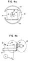
- the magnetic exciting and receiving coils or antennas for the reader are mounted at the end of the arm 12 in an antenna or coil housing 30 as shown in Figure 1 and in Figures 4a and 4b. Accordingly, with the arrangement according to the present invention, and as shown in Figure 2, the bin 14 can be read at any position during its up and down path, i.e. during its upward path and positions 1 and 2 or during its downward path in positions 4 and 5 after being emptied or dumped in position 3.
- the tag 24 preferably is the type which utilizes a single coil or antenna 26 both for receiving and for transmitting, with this single coil being coupled to the tag integrated circuit (IC) 28.
- the tag reader 32 includes an exciter coil 34 which, as shown, preferably includes a primary winding 36 connected to an oscillator and drive circuit 37 and a secondary winding 35 which in turn is connected to a capacitor 40 to form a resonant circuit at the exciter frequency.
- the reader 32 is provided with at least one receive coil 42, and preferably, as will be discussed in more detail below, a pair of parallel connected receive coils 42 and 44.
- receive coil 42 or coils 42, 44 are connected to a demodulator-decoder 46 which demodulates the received signal and decodes same to identify the bin 14 associated with the received code.
- the demodulated and decoded signal provide at the output of the unit 46 is then fed to a host computer 48 for storage and further data processing.
- the exciter coil 34 i.e. both the primary winding 36 and the secondary winding 35 are provided as shown in Figures 4a and 4b as helically wound solenoidal or solenoid type coils, with the axis of the solenoid type exciter coil 34 being substantially perpendicular to the plane of the tag coil 26.
- the exciter coil 34 is mounted on the front end of the robot arm 12 so that the axis of the coil 34 is substantially vertical as shown.
- the solenoidal exciter coil 34 is preferably provided with a rectangular shape in cross section, with the elongated side facing forward, i.e. toward the location of the tag 24. With this orientation, the magnetic excitation field lines 50 which clearly pass, as indicated, through the coil 26 of the tag 24.
- the reader receive coil 42 may be wound around the longitudinal axis of the solenoidal coil 34, and may be disposed adjacent one end of same.
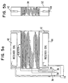
- the solenoidal exciter coils 36 and 38 are helically wound on a generally rectangular coil form 52 which is vertically mounted on the robot arm 12, i.e. the opening in the form is oriented vertically.
- the secondary winding 38 as indicated, has a substantially greater number of turns than the primary winding 36, which is interleaved with the secondary winding at one end thereof. It should be noted, however, that the primary winding 36 can equally be well be at the other end of the secondary winding 38 or disposed in the center thereof.
- a respective receiver coil 42 or 44 Disposed within the opening in the coil form 52 adjacent each end of the secondary winding 38, is a respective receiver coil 42 or 44.
- the receiver coils 42 and 44 are preferably wound flat, i.e. with the windings not being bundled or overlapped, and with the respective receiver coils 42 and 44 being disposed along the axis of the solenoidal exciter coil 34 (36, 35) and perpendicular, i.e. at a 90° angle, to the solenoidal exciter coil 34 or coil form 52.
- the receiver coils 42 and 44 are orientated such that their larger surfaces face the tag 24, with both of the receiver coils 42 and 44 having substantially the same orientation.
- the two receiver coils 42 and 44 are connected electrically in parallel and are wound or connected so that they are 180° out of phase.
- This coil configuration with the indicated connection effectively cancels out substantially all exciter interference and many other unwanted signals, while still favoring the orientation of the tag coil 26 when in a fringe of the reader area.
- the orientation ceases to be a problem.
- Figure 7 shows the excitation field lines 50 from the solenoidal excitation coil 34 relative to the orientation of the tag 26.
- the excitation field includes a further portion 50' extending from each end of the solenoidal coil 34 (only the excitation field lines 50' at one end of the solenoidal coil 34 being shown).
- the respective receiver coils 42 and 44 are disposed within the opening in the field lines 50 and within the major field lines 50' so that very little of this excitation field is coupled into the receiver coils 42 and 44.
- the coils 42 and 44 are wound and connected so that they are 180° out of phase (as indicated by the arrows adjacent the respective coils which denote the direction of winding of the coils). Thus, this tends to couple out other interfering signals. However, as will be appreciated, the field lines 56 transmitted by the tag 26 are received by the coils 42 and 44 to provide an increased range.
- the solenoidal exciter coil 34 is a solenoid type coil wound vertically on a form 52 having a height and width of 17" each and a depth of 3.5".
- the solenoidal coil 34 was wound with number 14 insulated wire with approximately one quarter inch spacing between the windings of a secondary winding 38 having 32 turns and between the windings of a primary winding 36 having 8 turns interleaved between turns of the secondary winding 38.
- Each of the receiver coils 42 and 44 is a flat wound coil with dimensions of three inches by fifteen inches on its broad surface and a thickness of one half inch .
- the coils 42 and 44 were mounted so that they were spaced approximately one and one half inches from the ends respective of the solenoidal exciter coil 34. With such a coil construction and an applied voltage of 24 volts DC at 750 ma., the tag could be turned on and data transmitted at a distance of thirty-eight inches, with an optimum orientation read being approximately 25-31 inches depending on the particular tag configuration.
- a simple switch 58 for example, a mercury switch, is mounted on the robot arm 12, preferably in a hidden position so as to be substantially tamper proof, for example, within the antenna housing 30, so that the contacts are normally open when the arm 12 is in the lowered position (positions 1 and 5 in Figure 2), and close when the arm 12 is raised so as to dump a bin or container 14 (position 3 in Figure 2).
- Closing of the contacts of the switch 58 is detected by the on-board computer 48, which likewise receives the decoded signal from the demodulator and decoder 46.
- the on-board computer 48 should receive signals from both the switch 58 and the demodulator and decoder 46.
- the computer 48 can thus count the number of dumps and determine whether there have been more dumps than recorded bin numbers to indicate a discrepancy.
- this latter feature is utilized together with the solenoidal exciter coil and receiver coil arrangement (34, 42, 44) for the reader according to the above described invention.
- the switch arrangement 58 may be utilized with any type of RFID reader, i.e. its usefulness is not limited to the preferred embodiment of the reader coil arrangement discussed above.
Abstract
Description
- The present invention relates to improved reader for a radio frequency identification (RFID) tag. More particularly, the present invention relates to an improved reader or reading arrangement mounted on the end of a robot arm, which is disposed on a waste or trash vehicle, for picking up containers or bins of trash waste or the like which are provided with an RFID tag.
- It has become increasingly usual in both commercial and residential waste or trash collection for the collector to provide customers with specially designed waste or trash bins which, for collection of the waste or trash, are engaged by a robot arm mounted on a trash or waste vehicle and are lifted vertically to empty the bins into the vehicle or trash truck. The empty bins are then lowered to the ground and returned to the customer. In order for the bins to be engaged and emptied in this manner, it is necessary for the customer to place the bin at a particular location, and preferably with a particular orientation. In the case of residential customers, this generally entails placing the bin adjacent to the curb on the collection day. In this way, the waste or trash truck can move along the curb and sequentially pickup and empty the bins disposed there for collection.
- Since the cost of waste or trash collection is often times dependent on the number of containers which are picked up in a given period of time and since, when private trash collection companies are involved, it is possible to have competing trash collection companies which collect trash on the same day, it is necessary to provide some identification on the individual trash bins or containers which identify the person to which the particular bin or container belongs. Although such identification can be visual, it is preferable to provide some kind of identification which can be read automatically so that the time for such identification can be reduced, and thus the efficiency of the trash collection process improved.
- One such type of identification which has been provided is an RFID tag attached to the container which identifies the container and thus the customer. Generally this tag is attached to the lid of the container or bin and is readable by a reader mounted on the truck. In one such known reader for this purpose, e.g. an inductive loop antenna disposed above the container or bin, the range of the reader is very limited so that difficulty in reading the tag results if the bin or container is not properly oriented adjacent to the curb. For example, if the tag is disposed toward the front of the bin or container, but the container is disposed adjacent to the curb so that it is rotated by 180°, whereby the front of the container faces away from the curb, the reading of the tag may not take place since the distance between the tag and the loop may be greater than the read range. This requires that the truck or vehicle operator or driver stop the vehicle and orient the bin or container prior to pickup by the robot arm. Obviously, this results in an increased cost for the collection operation.
- Therefore the primary object of the present invention to provide a reader for an RFID tag which can read the tag at larger distances and at various orientations so as to permit the reading of the tag even when the bin is not in the preferred orientation so that the driver may remain in the vehicle.
- WO92/09175 discloses a transponder system including a transponder and an interrogator having a transmission coil for producing a high-intensity electromagnetic field for inductively powering the transponder and two receiver coils for receiving a low-intensity electromagnetic field re-radiated by the transponder. The transponder uses a coil to derive both power and a clock pulse from the high-intensity field for powering and driving an identification circuit.
- The object is generally achieved according to the invention by a reader for a radio frequency identification tags which has at least one magnetic field transmitting and receiving coil oriented in a given plane and which is responsive to a received magnetic exciter field of a first frequency to produce and radiate an identifying magnetic field comprised of a carrier at a second different frequency modulated by an identifying code, with the reader comprising: first means for producing a radio frequency signal of the first frequency; a first magnetic field coupling arrangement connected to the output of the first means for producing a corresponding exciter field at the first frequency to be magnetically coupled to the receiving coil of the tag, a second magnetic field coupling arrangement for receiving a field of the second frequency produced by the tag and providing a corresponding electrical signal; circuitry connected to the at least one receiver coil for decoding the received electrical signal, characterised by said first magnetic field coupling arrangement including a solenoidal exciter coil having at least one wound exciter winding and a longitudinal axis disposed substantially perpendicular to the plane of the tag coil, and said second magnetic field coupling arrangement including at least one receiver coil disposed adjacent one end of the solenoidal coil, with said at least one receiver coil (42,44) being disposed along said longitudinal axis of said solenoidal exciter coil (34) and being oriented substantially perpendicular to said solenoidal exciter coil (34).
- According to the disclosed embodiment of the invention, at least the exciter and read coils of the reader are mounted on the end of a robot arm which is moveable in at least the vertical direction, the robot arm is mounted on a trash or waste collection type vehicle for at least vertical direction of movement, the axis of the solenoidal exciter coil is substantially vertical, and the robot arm is designed and used for picking up a trash bin or container having a radio frequency identification tag affixed to its lid with the tag coil being substantially horizontal.
- According to one embodiment of the invention, the receiver coil is wound around the axis of the solenoidal exciter coil.
- However, according to the preferred embodiment of the invention, the receiver coil is disposed along the longitudinal axis of the solenoidal exciter coil and is oriented substantially perpendicular to the solenoidal exciter coil. Still more preferably, a further receiver coil is disposed along the axis of the solenoidal exciter coil at an opposite end of the solenoidal exciter coil from the first receiver coil and is arranged substantially perpendicular to the solenoidal exciter coil, both receiver coils are flat coils, and the two receiver coils are connected in parallel and in phase opposition.
- According to a further feature of the invention, a switch is mounted on the end of the robot arm and is responsive to the position of the arm to be open when the arm is in a lowered position and to be closed when the arm is in a raised position to empty a bin into the truck, and means are disposed on the truck for counting and storing the number of closures of the switch.
-
- Figure 1 is a schematic side view showing a waste truck with a robot arm with a reader for engaging and lifting a waste bin provided with an RFID tag.
- Figure 2 is a schematic front view of a trash truck indicating the lifting and dumping of a trash or waste bin as shown in Figure 1.
- Figure 3 is a schematic block circuit diagram of an RFID tag and a reader according to an embodiment of the invention.
- Figures 4a and 4b are schematic top and side views showing the orientation of the reader exciter and reader coils relative to the RFID tag on the lid of the waste bin.
- Figures 5a and 5b are schematic side and end views, respectively, of the exciter coil and reader receiver coils according to the preferred embodiment of the invention.
- Figures 6a, 6b and 6c are schematic top, side and rear views, respectively, showing the geometrical arrangement of the exciter coil and the receiver coils relative to the tag coil according to the preferred embodiment of the invention shown in Figures 5a and 5b.
- Figure 7 is a schematic side view showing the exciter coil and the exciter field lines relative to the tag coil orientation to the invention.
- Figure 8 is a schematic side view showing the relative orientations of the exciter coil and the receiver coils, as shown in Figure 5a and 5b, relative to the excitation field and receive field from the tag for maximum rejection by the reader receiver coil(s) of the excitation field and noise, and for maximum coupling with the tag receive field transmitted by the tag.
-
- Referring now to Figures 1 and 2, there shown a waste or
trash truck 10 provided with arobot arm 12 which, in a known manner, is mounted on the side of thetruck 10 for lateral movement toward and away from a waste ortrash bin 14 and for vertical movement so as to be able to lift thebin 14 and empty same into the open top of thetruck 10. The relative directions of movement of therobot arm 12 are indicated by the double endedarrows 16 and 18 in Figure 1. The front end of therobot arm 12 is provided with a pair ofgripper arms 20 which, in a known manner, are controllable from on board the vehicle by the operator, and which can at least partially surround thebin 14 to grip same to permit lifting of thebin 14 as shown in Figure 2. - The waste or
trash bin 14 is provided with alid 22 which, in a known manner, is hinged along one side so that it can swing open for the insertion of waste or trash and/or when thebin 14 is inverted for dumping as shown in Figure 2. In order to identify thecontainer 14, anRFID tag 24 is mounted in or on thelid 22 at a desired location, e.g. in the center as shown or possibly toward the front. Thetag 24 is of the type which is responsive to an excitation magnetic field or signal of a first frequency to generate a magnetic field or signal of a second frequency which is modulated with a coded signal identifying thebin 14. Such RFID tags are well known in the art. While any tag which operates in this manner may be utilized, preferably the RFID tag is of the type disclosed in commonly assigned U.S. Patent No. 5,099,227 (but utilizing only magnetic coupling) with a single coil used both for excitation and for information transmission. A specific physical embodiment of a preferred tag which can be utilized is disclosed in commonly assigned co-pending U.S. Patent Application No. 07/823,784, filed January 22, 1992, now U.S. Patent No. 5,382,784, issued on January 17, 1995. In general, such a tag includes as schematically shown in Figure 4a, a relatively flat orthin coil 26 connected to an integrated circuit (IC) 28 disposed within the confines of thecoil 26. Thus, thecoil 26 ofRFID tag 24 is disposed substantially in a horizontal plane within thelid 22 of thebin 14. - In order to read the
tag 24, an RFID reader, for example of the type generally shown in the above mentioned commonly assigned U.S. Patent, is mounted on thetruck 10. To couple the exciter magnetic field of the first frequency to thetag 24 and to receive the modulated magnetic field of the second frequency transmitted from thetag 24, according to the present invention the magnetic exciting and receiving coils or antennas for the reader are mounted at the end of thearm 12 in an antenna orcoil housing 30 as shown in Figure 1 and in Figures 4a and 4b. Accordingly, with the arrangement according to the present invention, and as shown in Figure 2, thebin 14 can be read at any position during its up and down path, i.e. during its upward path andpositions 1 and 2 or during its downward path inpositions 4 and 5 after being emptied or dumped inposition 3. - Turning now to Figure 3, there is shown a basic block circuit for the preferred embodiment of the reader and tag used for the present invention. As indicated above, the
tag 24 preferably is the type which utilizes a single coil orantenna 26 both for receiving and for transmitting, with this single coil being coupled to the tag integrated circuit (IC) 28. To excite thetag 24, the tag reader 32 includes anexciter coil 34 which, as shown, preferably includes aprimary winding 36 connected to an oscillator and drive circuit 37 and a secondary winding 35 which in turn is connected to a capacitor 40 to form a resonant circuit at the exciter frequency. To receive or couple in the magnetic field at the second frequency transmitted by thecoil 26 of thetag 24, the reader 32 is provided with at least one receivecoil 42, and preferably, as will be discussed in more detail below, a pair of parallel connected receivecoils coil 42 orcoils bin 14 associated with the received code. The demodulated and decoded signal provide at the output of the unit 46 is then fed to a host computer 48 for storage and further data processing. - According to the invention, in order to provide an extended range for reading of the
tag 24, theexciter coil 34, i.e. both theprimary winding 36 and the secondary winding 35 are provided as shown in Figures 4a and 4b as helically wound solenoidal or solenoid type coils, with the axis of the solenoidtype exciter coil 34 being substantially perpendicular to the plane of thetag coil 26. In the illustrated embodiment of the invention with thetag coil 26 being oriented in a substantially horizontal plane, theexciter coil 34 is mounted on the front end of therobot arm 12 so that the axis of thecoil 34 is substantially vertical as shown. Preferably, as further shown in Figures 4a and 4b, thesolenoidal exciter coil 34 is preferably provided with a rectangular shape in cross section, with the elongated side facing forward, i.e. toward the location of thetag 24. With this orientation, the magneticexcitation field lines 50 which clearly pass, as indicated, through thecoil 26 of thetag 24. As shown in Figure 4b, the reader receivecoil 42 may be wound around the longitudinal axis of thesolenoidal coil 34, and may be disposed adjacent one end of same. - Turning now to Figures 5a, 5b and 6a-6c, there is shown a preferred embodiment of the arrangement for the
solenoidal exciter coil 34 and thereceiver coil 42, and preferably receivingcoils solenoidal exciter coils rectangular coil form 52 which is vertically mounted on therobot arm 12, i.e. the opening in the form is oriented vertically. Thesecondary winding 38, as indicated, has a substantially greater number of turns than theprimary winding 36, which is interleaved with the secondary winding at one end thereof. It should be noted, however, that theprimary winding 36 can equally be well be at the other end of thesecondary winding 38 or disposed in the center thereof. Disposed within the opening in thecoil form 52 adjacent each end of the secondary winding 38, is arespective receiver coil solenoidal exciter coil 34 orcoil form 52. As can be seen in Figure 6a-6c, the receiver coils 42 and 44 are orientated such that their larger surfaces face thetag 24, with both of the receiver coils 42 and 44 having substantially the same orientation. As further shown in Figure 5a (and in Figure 3) the tworeceiver coils tag coil 26 when in a fringe of the reader area. However, as the tag comes closer to the reader coils, the orientation ceases to be a problem. - Turning now to Figures 7 and 8, the field lines for the various magnetic fields involved between the
tag 26 and thecoils excitation field lines 50 from thesolenoidal excitation coil 34 relative to the orientation of thetag 26. In addition to the donut shapedexcitation field lines 52 shown in Figure 7, which tend to excite thetag 26 with the given orientation, as shown in Figure 8, the excitation field includes a further portion 50' extending from each end of the solenoidal coil 34 (only the excitation field lines 50' at one end of thesolenoidal coil 34 being shown). The respective receiver coils 42 and 44 are disposed within the opening in the field lines 50 and within the major field lines 50' so that very little of this excitation field is coupled into the receiver coils 42 and 44. As indicated above, thecoils tag 26 are received by thecoils - As an example of an exciter and receiver coil arrangement built according to the preferred embodiment of the invention shown in Figures 5a and 5b, the
solenoidal exciter coil 34 is a solenoid type coil wound vertically on aform 52 having a height and width of 17" each and a depth of 3.5". Thesolenoidal coil 34 was wound withnumber 14 insulated wire with approximately one quarter inch spacing between the windings of a secondary winding 38 having 32 turns and between the windings of a primary winding 36 having 8 turns interleaved between turns of the secondary winding 38. Each of the receiver coils 42 and 44 is a flat wound coil with dimensions of three inches by fifteen inches on its broad surface and a thickness of one half inch . Thecoils solenoidal exciter coil 34. With such a coil construction and an applied voltage of 24 volts DC at 750 ma., the tag could be turned on and data transmitted at a distance of thirty-eight inches, with an optimum orientation read being approximately 25-31 inches depending on the particular tag configuration. - Finally, a further problem with waste
collection utilizing bins 14, is the problem of truck operators lifting and dumpingextra waste bins 14 which are not provided withRFID identifying tags 24, and thus for which the truck owner will receive no payment, since there will be no record of such bins being lifted and dumped. To avoid this problem, according to a further feature of the invention, asimple switch 58, for example, a mercury switch, is mounted on therobot arm 12, preferably in a hidden position so as to be substantially tamper proof, for example, within theantenna housing 30, so that the contacts are normally open when thearm 12 is in the lowered position (positions 1 and 5 in Figure 2), and close when thearm 12 is raised so as to dump a bin or container 14 (position 3 in Figure 2). Closing of the contacts of theswitch 58 is detected by the on-board computer 48, which likewise receives the decoded signal from the demodulator and decoder 46. Thus, for each bin orcontainer 14 which is dumped or emptied into thetruck 10, the on-board computer 48 should receive signals from both theswitch 58 and the demodulator and decoder 46. The computer 48 can thus count the number of dumps and determine whether there have been more dumps than recorded bin numbers to indicate a discrepancy. Preferably this latter feature is utilized together with the solenoidal exciter coil and receiver coil arrangement (34, 42, 44) for the reader according to the above described invention. However, it is to be understood that theswitch arrangement 58 may be utilized with any type of RFID reader, i.e. its usefulness is not limited to the preferred embodiment of the reader coil arrangement discussed above.
Claims (15)
- A reader (32) for reading radio frequency identification tags (24) having at least one magnetic field transmitting and receiving coil (26) which is oriented in a given plane and which is responsive to a received magnetic exciter field of a first frequency to produce and radiate an identifying magnetic field comprised of a carrier at a second different frequency modulated by an identifying code; said reader comprising:first means (37) for producing a radio frequency signal of the first frequency;a first magnetic field coupling arrangement (34,36,38) connected to the output of said first means (37) for producing a corresponding exciter field at said first frequency to be magnetically coupled to the receiving coil (26) of the tag (24);a second magnetic field coupling arrangement (42,44) for receiving a field of said second frequency produced by the tag (24) and providing a corresponding electrical signal;circuitry connected to said at least one receiver coil (42,44) for decoding the received electrical signal, which reader (32) is characterised by said first magnetic field coupling arrangement (34,36,38) including a solenoidal exciter coil (34) having at least one wound exciter winding, and a longitudinal axis disposed substantially perpendicular to the plane of the tag coil (26); andsaid second magnetic field coupling arrangement including at least one receiver coil (42,44) disposed adjacent one end of said solenoidal coil (34), with said at least one receiver coil (42,44) being disposed along said longitudinal axis of said solenoidal exciter coil (34) and being oriented substantially perpendicular to said solenoidal exciter coil (34).
- A reader (32) as defined in Claim 1, wherein said reader is mounted on the end of a robot arm (12) which is moveable in at least the vertical direction.
- A reader (32) as defined in Claim 2, wherein said robot arm (12) is mounted on a vehicle (10) for said movement in at least the vertical direction, and said axis of said solenoidal coil (34) is substantially vertical.
- A reader (32) according to any preceding claim, wherein the radio frequency identification tags (24) are affixed to a trash bin and said reader is mourned on the end of a robot arm (12), which is mounted on a trash truck (10) and which is designed and used for picking up a trash bin (14) having a radio frequency identification tag (24) affixed to its lid (22).
- A reader (32) according to any preceding claim, wherein said at least one receiver coil (42,44) is wound concentric with said axis of said solenoidal coil (34).
- A reader (32) according to any one of Claim 4, wherein said at least one receiver coil (42,44) is disposed along said longitudinal axis of said solenoidal exciter coil (34) and is oriented substantially perpendicular to said solenoidal exciter coil (34).
- A reader (32) according to any one of Claims 1 to 4 or 6 including a further said receiver coil (42,44) disposed along said axis of said solenoidal exciter coil (34) adjacent an opposite end of said solenoidal exciter coil (34) and arranged substantially perpendicular to said solenoidal exciter coil (34).
- A reader (32) as defined in Claim 7, wherein said receiver coils (42,44) are flat coils.
- A reader (32) as defined in Claim 7, wherein said receiver coils (42,44) are connected in parallel and in phase opposition.
- A reader (32) according to any preceding claim, wherein said solenoidal exciter coil (34) includes a primary winding (36) connected to said first means (37) and a secondary winding (38) connected in parallel with a capacitor (40) and forming a circuit resonant at said first frequency.
- A reader (32) according to any one of Claims 2, 3, 4 or 6 further comprising: a switch (58) mounted on said end of said robot arm (12) and responsive to the position of said arm (12) to have open contacts when said arm (12) is in a lowered position and to have closed contacts when said arm (12) is in a raised position to empty a bin into said truck (10); and means (48) for counting and storing the number of closures of said switch (58).
- A reader (32) as defined in Claim 11, wherein said switch (58) is a mercury switch.
- A reader (32) as defined in Claim 5, including a further said receiver coil (42,44) disposed along said axis of said solenoidal exciter coil (34) adjacent an opposite end of said solenoidal exciter coil (34) and wound concentric with said axis of said solenoidal exciter coil (35).
- A reader (32) as defined in Claim 13, wherein said receiver coils (42,44) are connected in parallel and in phase opposition.
- A reader (32) as defined in Claim 7, wherein said solenoidal exciter coil (35) produces a toroidal shaped excitation field (50) and a respective field portion (50') enclosing each end of said exciter coil (35); and said receiver coils (42,44) are disposed substantially within the center opening of said toroidal shaped excitation field (50) and within major field lines of the respective end field portions (50'), whereby little of the excitation field is coupled into the respective receiver coils.
Applications Claiming Priority (5)
| Application Number | Priority Date | Filing Date | Title |
|---|---|---|---|
| US23247894A | 1994-04-25 | 1994-04-25 | |
| US232478 | 1994-04-25 | ||
| US312199 | 1994-09-26 | ||
| US08/312,199 US5565846A (en) | 1994-04-25 | 1994-09-26 | Reader system for waste bin pickup vehicles |
| PCT/US1995/004825 WO1995029456A1 (en) | 1994-04-25 | 1995-04-25 | Reader system for waste bin pickup vehicles |
Publications (2)
| Publication Number | Publication Date |
|---|---|
| EP0760985A1 EP0760985A1 (en) | 1997-03-12 |
| EP0760985B1 true EP0760985B1 (en) | 2000-03-08 |
Family
ID=26926041
Family Applications (1)
| Application Number | Title | Priority Date | Filing Date |
|---|---|---|---|
| EP95917068A Expired - Lifetime EP0760985B1 (en) | 1994-04-25 | 1995-04-25 | Reader system for waste bin pickup vehicles |
Country Status (5)
| Country | Link |
|---|---|
| US (1) | US5565846A (en) |
| EP (1) | EP0760985B1 (en) |
| AU (1) | AU719512B2 (en) |
| DE (1) | DE69515478T2 (en) |
| WO (1) | WO1995029456A1 (en) |
Cited By (10)
| Publication number | Priority date | Publication date | Assignee | Title |
|---|---|---|---|---|
| US7336183B2 (en) | 2004-04-30 | 2008-02-26 | Kimberly-Clark Worldwide, Inc. | Decommissioning an electronic data tag |
| US7501951B2 (en) | 2006-09-06 | 2009-03-10 | Casella Waste Systems, Inc. | Systems and methods for identifying and collecting banned waste |
| US7511611B2 (en) | 2006-05-18 | 2009-03-31 | Casella Waste Systems, Inc. | Systems for and methods of asset management in a waste management service environment |
| ES2320289A1 (en) * | 2006-02-27 | 2009-05-20 | Clime, S.A. | Procedure and system for the optimization of the collection and transportation of solid waste (Machine-translation by Google Translate, not legally binding) |
| US7561045B2 (en) | 2006-09-06 | 2009-07-14 | Casella Waste Systems, Inc. | Systems and methods for indicating a quality of grouped items |
| DE102008049744A1 (en) * | 2008-09-30 | 2010-04-01 | Sulo Umwelttechnik Gmbh | RFID antenna |
| US7701346B2 (en) | 2004-04-30 | 2010-04-20 | Jeffrey Dean Lindsay | Deactivating a data tag for user privacy or tamper-evident packaging |
| US7728730B2 (en) | 2006-09-06 | 2010-06-01 | Casella Waste Systems, Inc | Systems and methods for measuring the purity of bales of recyclable materials |
| US7870042B2 (en) | 2006-05-15 | 2011-01-11 | Casella Waste Systems, Inc. | Systems and methods for identifying banned waste in a municipal solid waste environment |
| US7948381B2 (en) | 2004-04-30 | 2011-05-24 | Binforma Group Limited Liability Company | Reversibly deactivating a radio frequency identification data tag |
Families Citing this family (104)
| Publication number | Priority date | Publication date | Assignee | Title |
|---|---|---|---|---|
| US5838233A (en) * | 1996-08-16 | 1998-11-17 | Delco Electronics Corporation | Object orientation sensor device |
| IL119509A (en) * | 1996-10-28 | 2000-02-17 | Hi G Tek Ltd | Electronic tag |
| WO1998038593A1 (en) * | 1997-02-28 | 1998-09-03 | Moba Mobile Automation Gmbh | Container identification system on side-loading refuse collection vehicles with gripper arms |
| US5929760A (en) * | 1997-10-20 | 1999-07-27 | Escort Memory Systems | RFID conveyor antenna |
| US6206282B1 (en) | 1998-03-03 | 2001-03-27 | Pyper Products Corporation | RF embedded identification device |
| US6154137A (en) | 1998-06-08 | 2000-11-28 | 3M Innovative Properties Company | Identification tag with enhanced security |
| US7044373B1 (en) | 1998-08-14 | 2006-05-16 | 3M Innovative Properties Company | Radio frequency identification systems applications |
| EP1770591B1 (en) | 1998-08-14 | 2010-04-28 | 3M Innovative Properties Company | RFID reader |
| US6424262B2 (en) | 1998-08-14 | 2002-07-23 | 3M Innovative Properties Company | Applications for radio frequency identification systems |
| JP2002522999A (en) | 1998-08-14 | 2002-07-23 | スリーエム イノベイティブ プロパティズ カンパニー | Applications to radio frequency identification systems |
| US6060992A (en) * | 1998-08-28 | 2000-05-09 | Taiwan Semiconductor Manufacturing Co., Ltd. | Method and apparatus for tracking mobile work-in-process parts |
| FR2784364B1 (en) * | 1998-10-13 | 2000-12-15 | Plastic Omnium Cie | BIN FOR THE COLLECTION OF WASTE, EQUIPPED WITH A TRANSPONDER |
| US6468638B2 (en) | 1999-03-16 | 2002-10-22 | Alien Technology Corporation | Web process interconnect in electronic assemblies |
| DE10024927A1 (en) * | 1999-08-03 | 2001-07-05 | Aeg Identifikationssys Gmbh | Transponder system has reader arrangement arranged near container holding device and that communicates contactlessly with transponder of container within holding device |
| WO2003030120A1 (en) * | 1999-12-16 | 2003-04-10 | Cardinal Automation, Inc. | System for auditing refuse collection |
| US7342496B2 (en) | 2000-01-24 | 2008-03-11 | Nextreme Llc | RF-enabled pallet |
| US6943678B2 (en) | 2000-01-24 | 2005-09-13 | Nextreme, L.L.C. | Thermoformed apparatus having a communications device |
| US8077040B2 (en) | 2000-01-24 | 2011-12-13 | Nextreme, Llc | RF-enabled pallet |
| JP3690953B2 (en) * | 2000-02-23 | 2005-08-31 | 松下電器産業株式会社 | Delivery article handling system and delivery article handling method |
| US6606247B2 (en) | 2001-05-31 | 2003-08-12 | Alien Technology Corporation | Multi-feature-size electronic structures |
| AU2002357056A1 (en) * | 2001-12-03 | 2003-06-17 | Philip M. Anderson Iii | Portable surgical implement detector |
| US7214569B2 (en) | 2002-01-23 | 2007-05-08 | Alien Technology Corporation | Apparatus incorporating small-feature-size and large-feature-size components and method for making same |
| US7198193B2 (en) * | 2002-06-24 | 2007-04-03 | Datamars S.A. | Method and apparatus for identifying a set of multiple items on conveyor system with multiread transponders |
| US7253735B2 (en) | 2003-03-24 | 2007-08-07 | Alien Technology Corporation | RFID tags and processes for producing RFID tags |
| US20050197062A1 (en) * | 2004-03-02 | 2005-09-08 | Peter Sprogis | Method and apparatus for transponder initiated messaging |
| US7602284B2 (en) * | 2004-03-04 | 2009-10-13 | Ethicon, Inc. | Sterilizer cassette handling system with data link |
| US7309014B2 (en) * | 2004-03-04 | 2007-12-18 | Ethicon, Inc. | Sterilizer cassette handling system with dual visual code reading |
| US8440139B2 (en) * | 2004-03-04 | 2013-05-14 | Ethican, Inc. | Method of delivering liquid sterilant to a sterilizer |
| US7151455B2 (en) * | 2004-04-30 | 2006-12-19 | Kimberly-Clark Worldwide, Inc. | Activating a data tag by load or orientation or user control |
| US20050263421A1 (en) * | 2004-05-28 | 2005-12-01 | Kohler James P | Cassette with encoded lumen claim |
| US20050263422A1 (en) * | 2004-05-28 | 2005-12-01 | Kohler James P | Cassette assembly |
| US7452504B2 (en) * | 2004-05-28 | 2008-11-18 | Ethicon, Inc. | Sterilization/disinfection cycle control |
| GB2416612A (en) * | 2004-07-22 | 2006-02-01 | Lorna Louise Langdon | On-cart recycling data collection system |
| US20060061481A1 (en) * | 2004-09-23 | 2006-03-23 | Kurple William M | Receptacle locator |
| CA2582382A1 (en) | 2004-10-07 | 2006-04-20 | West Pharmaceutical Services, Inc. | Closure for a container |
| US7811530B2 (en) | 2004-10-29 | 2010-10-12 | Ethicon, Inc. | Sterilization cassette and packaging |
| US7615479B1 (en) | 2004-11-08 | 2009-11-10 | Alien Technology Corporation | Assembly comprising functional block deposited therein |
| US7353598B2 (en) | 2004-11-08 | 2008-04-08 | Alien Technology Corporation | Assembly comprising functional devices and method of making same |
| US7551141B1 (en) | 2004-11-08 | 2009-06-23 | Alien Technology Corporation | RFID strap capacitively coupled and method of making same |
| US7688206B2 (en) | 2004-11-22 | 2010-03-30 | Alien Technology Corporation | Radio frequency identification (RFID) tag for an item having a conductive layer included or attached |
| US7385284B2 (en) | 2004-11-22 | 2008-06-10 | Alien Technology Corporation | Transponder incorporated into an electronic device |
| US7330128B1 (en) | 2005-05-23 | 2008-02-12 | Thomas Lombardo | System and method for detecting radiological waste by trash collection vehicles |
| US7542301B1 (en) | 2005-06-22 | 2009-06-02 | Alien Technology Corporation | Creating recessed regions in a substrate and assemblies having such recessed regions |
| US20070031992A1 (en) * | 2005-08-05 | 2007-02-08 | Schatz Kenneth D | Apparatuses and methods facilitating functional block deposition |
| US7298271B2 (en) * | 2005-09-19 | 2007-11-20 | Peter Sprogis | Method and apparatus for providing awards using transponders |
| US8560459B2 (en) | 2005-11-17 | 2013-10-15 | Casella Waste Systems, Inc. | Methods and facilities for a municipal solid waste management system |
| US20070276686A1 (en) * | 2006-01-20 | 2007-11-29 | Count & Crush, Llc | Techniques for processing recyclable containers |
| US20070174071A1 (en) | 2006-01-20 | 2007-07-26 | C&C Acquisition, Llc | Techniques for managing information relating to recyclable containers |
| US20070185612A1 (en) * | 2006-02-08 | 2007-08-09 | Casella Waste Systems, Inc. | Systems and methods for managing inventory of aggregated post-consumer goods |
| US8020767B2 (en) * | 2006-03-21 | 2011-09-20 | Casella Waste Systems, Inc. | Systems and methods for monitoring a quantity of waste in a waste transfer station environment |
| US20070273471A1 (en) * | 2006-05-05 | 2007-11-29 | Casella Waste Systems, Inc. | Systems and methods for controlling access to a site using a combination of identification technologies |
| WO2008002573A2 (en) * | 2006-06-27 | 2008-01-03 | Intercept Pharmaceuticals, Inc. | Bile acid derivatives as fxr ligands for the prevention or treatment of fxr-mediated deseases or conditions |
| US20080077541A1 (en) * | 2006-09-06 | 2008-03-27 | Casella Waste Systems, Inc. | Systems and methods for using billing information to dynamically route vehicles |
| US20080093436A1 (en) * | 2006-10-23 | 2008-04-24 | Cascade Engineering, Inc. | Waste/recycling container with rfid device |
| US20080094224A1 (en) * | 2006-10-23 | 2008-04-24 | Cascade Engineering, Inc. | Rfid-enabled waste/recycling cart |
| US8820639B2 (en) * | 2006-11-03 | 2014-09-02 | Assa Abloy Ab | Security feature RFID card |
| US20080106379A1 (en) * | 2006-11-03 | 2008-05-08 | Lasercard Corporation | Antenna using optical recording media |
| US20080201388A1 (en) * | 2007-02-20 | 2008-08-21 | Luke Wood | System and method for equipment tracking and preventative maintenance scheduling and verification |
| EP2126810A4 (en) | 2007-02-21 | 2011-10-26 | Advanced Custom Engineered Systems & Equipment Co | System for monitoring a container and the items therein |
| US20080251968A1 (en) * | 2007-04-10 | 2008-10-16 | Cascade Engineering, Inc. | Rfid hard case device and method of manufacture |
| US9634730B2 (en) * | 2007-07-09 | 2017-04-25 | Qualcomm Incorporated | Wireless energy transfer using coupled antennas |
| MX2008012207A (en) * | 2007-09-24 | 2009-04-15 | Rehrig Pacific Co | Trackable cart. |
| GB0812021D0 (en) * | 2008-07-02 | 2008-08-06 | Amway Europ Ltd | Electromagnetic interference mitigation |
| US20100071572A1 (en) * | 2008-09-23 | 2010-03-25 | Carroll Robert B | Waste compactor and container monitoring system |
| US7924165B2 (en) * | 2008-09-25 | 2011-04-12 | Ztoa Innovations, Llc | Electronic shark deterrent |
| GB2464272B (en) * | 2008-10-07 | 2011-02-02 | Advanced Mfg Control Systems Ltd | A waste management system for associating refuse bins to corresponding users |
| US8185277B2 (en) * | 2008-11-07 | 2012-05-22 | Advanced Custom Engineered Systems & Equipment Co. | Waste removing and hauling vehicle |
| US20100119341A1 (en) * | 2008-11-07 | 2010-05-13 | Advanced Custom Engineered Systems & Equipment Co. | Method and apparatus for waste removing and hauling |
| US8146798B2 (en) | 2008-11-07 | 2012-04-03 | Advanced Custom Engineered Systems & Equipment Co. | Method and apparatus for monitoring waste removal and administration |
| US8330059B2 (en) * | 2009-01-15 | 2012-12-11 | The Curotto-Can, Inc. | Automated collection and scale system |
| US8753062B2 (en) * | 2009-01-16 | 2014-06-17 | The Curotto-Can, Llc | Gripper system |
| US11725977B2 (en) | 2009-02-19 | 2023-08-15 | The Heil Co. | Automated collection and scale system |
| US8979142B2 (en) | 2009-05-05 | 2015-03-17 | The Curotto-Can, Llc | Locking mechanism |
| FR2950871B1 (en) | 2009-10-02 | 2012-01-20 | Plastic Omnium Cie | DEVICE FOR COLLECTING WASTE, SUCH AS A COLLECTION TRUCK |
| US8556117B2 (en) | 2010-04-30 | 2013-10-15 | The Curotto-Can, Llc | Automated cover |
| US9054542B2 (en) | 2010-06-10 | 2015-06-09 | Access Business Group International Llc | Coil configurations for inductive power transfer |
| US9067730B2 (en) | 2011-04-29 | 2015-06-30 | The Curotto-Can, Llc. | Light-weight collection bin and waste systems including a light-weight collection bin |
| US9103909B2 (en) * | 2011-12-30 | 2015-08-11 | Lyngose Systems Ltd. | System and method for determining whether an object is located within a region of interest |
| JP6193882B2 (en) | 2012-01-06 | 2017-09-06 | アクセス ビジネス グループ インターナショナル リミテッド ライアビリティ カンパニー | Wireless power receiver system |
| WO2013112526A1 (en) | 2012-01-24 | 2013-08-01 | Access Business Group International Llc | Wireless power control system |
| US8645189B2 (en) | 2012-06-12 | 2014-02-04 | International Business Machines Corporation | Leveraging RFID generated consumer behavior through a web map service |
| CN103683523B (en) | 2012-09-07 | 2018-04-13 | 捷通国际有限公司 | System and method for double-direction radio power transmission |
| US9912166B2 (en) | 2012-09-11 | 2018-03-06 | Access Business Group International Llc | Wireless power control |
| AU2013205211B2 (en) * | 2012-10-23 | 2016-05-12 | Xorro Pty Ltd | Distributed Monitoring System and Waste Management System and Method |
| US9208362B1 (en) | 2013-03-11 | 2015-12-08 | United States Of America As Represented By The Administrator Of The National Aeronautics And Space Administration | Methods, systems and apparatuses for radio frequency identification |
| WO2014174153A1 (en) | 2013-04-24 | 2014-10-30 | Teknologian Tutkimuskeskus Vtt | Rfid system with transmission line antenna and related methods |
| US9251388B2 (en) * | 2013-05-15 | 2016-02-02 | Advanced Custom Engineered Systems & Equipment, Co. | Method for deploying large numbers of waste containers in a waste collection system |
| US9735584B2 (en) | 2013-10-17 | 2017-08-15 | Access Business Group International Llc | Wireless power communication |
| US9296326B1 (en) * | 2015-01-02 | 2016-03-29 | Tim Young | System and method for collecting recycling materials |
| MX368185B (en) | 2015-05-06 | 2019-09-23 | Crown Equip Corp | Diagnostic tag for an industrial vehicle tag reader. |
| BR112017023812A2 (en) | 2015-05-06 | 2018-07-31 | Crown Equip Corp | "industrial vehicle and system". |
| BE1024077A9 (en) * | 2015-08-03 | 2017-11-16 | De Vliet Ronny Van | RADIO FREQUENCY IDENTIFICATION ANTENNA HOUSING FOR INDUSTRIAL APPLICATIONS |
| WO2017173381A1 (en) | 2016-03-31 | 2017-10-05 | Advanced Custom Engineered Systems & Equipment Company | Systems & method for interrogating, publishing and analyzing information related to a waste hauling vehicle |
| US10221012B2 (en) | 2016-06-03 | 2019-03-05 | The Heil Co. | Grabber for a front loader refuse vehicle |
| WO2018035297A1 (en) | 2016-08-17 | 2018-02-22 | Fowling Enterprises, Llc | Automated game scoring and pin tracking system |
| US9824337B1 (en) * | 2016-12-19 | 2017-11-21 | Rubicon Global Holdings, Llc | Waste management system implementing receptacle tracking |
| WO2018129316A1 (en) * | 2017-01-05 | 2018-07-12 | Mallady Roy | Container transporter and methods |
| WO2018145176A1 (en) * | 2017-02-10 | 2018-08-16 | Freitas Francineide | Smart rfid rubbish bin |
| DE102017001865A1 (en) * | 2017-03-01 | 2018-09-06 | Va-Q-Tec Ag | Method for checking the functionality of the heat insulation of a transport container |
| US11144056B1 (en) | 2018-01-12 | 2021-10-12 | AI Incorporated | Autonomous refuse container replacement system |
| US11144066B1 (en) | 2018-01-31 | 2021-10-12 | AI Incorporated | Autonomous refuse bag replacement system |
| EP3671664A1 (en) * | 2018-12-21 | 2020-06-24 | emz-Hanauer GmbH & Co. KGaA | System for operating a refuse container and method for operating a refuse container |
| US11673703B1 (en) | 2019-06-07 | 2023-06-13 | Wm Recycle America, L.L.C. | Apparatus and method for applying labels to a customer container from a waste collection, disposal and/or recycling vehicle |
| US11840271B2 (en) | 2020-06-25 | 2023-12-12 | Rehrig Pacific Company | Pallet sled and delivery system |
Family Cites Families (8)
| Publication number | Priority date | Publication date | Assignee | Title |
|---|---|---|---|---|
| US5012236A (en) * | 1989-05-26 | 1991-04-30 | Trovan Limited | Electromagnetic energy transmission and detection apparatus |
| AU665929B2 (en) * | 1989-05-26 | 1996-01-25 | Trovan Limited | Method and apparatus for modulating and dectecting a subcarrier signal for an inductively coupled transponder |
| US5099227A (en) * | 1989-07-18 | 1992-03-24 | Indala Corporation | Proximity detecting apparatus |
| US5099226A (en) * | 1991-01-18 | 1992-03-24 | Interamerican Industrial Company | Intelligent security system |
| US5119894A (en) * | 1991-02-19 | 1992-06-09 | Toter, Inc. | Weighing apparatus for weighing the contents of a refuse container and method |
| US5230393A (en) * | 1991-06-27 | 1993-07-27 | Mezey Armand G | Refuse collection and weighing system |
| DE4125312A1 (en) * | 1991-07-31 | 1993-02-04 | Fac Frank Abels Consult & Tech | Measuring contents weight of identifiable refuse container - weighing container on collection vehicle before and after emptying, storing measured weight and detected identity |
| US5221831A (en) * | 1991-11-29 | 1993-06-22 | Indala Corporation | Flap-type portal reader |
-
1994
- 1994-09-26 US US08/312,199 patent/US5565846A/en not_active Expired - Lifetime
-
1995
- 1995-04-25 DE DE69515478T patent/DE69515478T2/en not_active Expired - Fee Related
- 1995-04-25 WO PCT/US1995/004825 patent/WO1995029456A1/en active IP Right Grant
- 1995-04-25 AU AU23899/95A patent/AU719512B2/en not_active Ceased
- 1995-04-25 EP EP95917068A patent/EP0760985B1/en not_active Expired - Lifetime
Cited By (13)
| Publication number | Priority date | Publication date | Assignee | Title |
|---|---|---|---|---|
| US7948381B2 (en) | 2004-04-30 | 2011-05-24 | Binforma Group Limited Liability Company | Reversibly deactivating a radio frequency identification data tag |
| US7701346B2 (en) | 2004-04-30 | 2010-04-20 | Jeffrey Dean Lindsay | Deactivating a data tag for user privacy or tamper-evident packaging |
| US7336183B2 (en) | 2004-04-30 | 2008-02-26 | Kimberly-Clark Worldwide, Inc. | Decommissioning an electronic data tag |
| ES2320289A1 (en) * | 2006-02-27 | 2009-05-20 | Clime, S.A. | Procedure and system for the optimization of the collection and transportation of solid waste (Machine-translation by Google Translate, not legally binding) |
| US7870042B2 (en) | 2006-05-15 | 2011-01-11 | Casella Waste Systems, Inc. | Systems and methods for identifying banned waste in a municipal solid waste environment |
| US7511611B2 (en) | 2006-05-18 | 2009-03-31 | Casella Waste Systems, Inc. | Systems for and methods of asset management in a waste management service environment |
| US7501951B2 (en) | 2006-09-06 | 2009-03-10 | Casella Waste Systems, Inc. | Systems and methods for identifying and collecting banned waste |
| US7561045B2 (en) | 2006-09-06 | 2009-07-14 | Casella Waste Systems, Inc. | Systems and methods for indicating a quality of grouped items |
| US7728730B2 (en) | 2006-09-06 | 2010-06-01 | Casella Waste Systems, Inc | Systems and methods for measuring the purity of bales of recyclable materials |
| US7994909B2 (en) | 2006-09-06 | 2011-08-09 | Casella Waste Systems, Inc. | Systems and methods for identifying and collecting banned waste |
| US8068029B2 (en) | 2006-09-06 | 2011-11-29 | Re Community Holdings Ii, Inc. | Systems and methods for indicating a quality of grouped items |
| US8542121B2 (en) | 2006-09-06 | 2013-09-24 | Casella Waste Systems, Inc. | Systems and methods for identifying and collecting banned waste |
| DE102008049744A1 (en) * | 2008-09-30 | 2010-04-01 | Sulo Umwelttechnik Gmbh | RFID antenna |
Also Published As
| Publication number | Publication date |
|---|---|
| EP0760985A1 (en) | 1997-03-12 |
| AU2389995A (en) | 1995-11-16 |
| US5565846A (en) | 1996-10-15 |
| WO1995029456A1 (en) | 1995-11-02 |
| DE69515478D1 (en) | 2000-04-13 |
| AU719512B2 (en) | 2000-05-11 |
| DE69515478T2 (en) | 2000-10-19 |
Similar Documents
| Publication | Publication Date | Title |
|---|---|---|
| EP0760985B1 (en) | Reader system for waste bin pickup vehicles | |
| AU634789B2 (en) | Electromagnetic energy transmission and detection system | |
| CN1150497C (en) | Identification tag with enhanced security | |
| US5491483A (en) | Single loop transponder system and method | |
| US5461386A (en) | Inductor/antenna for a recognition system | |
| EP0782214B1 (en) | Ring antennas for resonant cicuits | |
| EP0715045B1 (en) | Lock having inductive key detection and method of construction | |
| US5701121A (en) | Transducer and interrogator device | |
| EP0409880B1 (en) | Actuator and communication system | |
| AU723295B2 (en) | Apparatus for magnetically decoupling an RFID tag | |
| US6848621B2 (en) | Transponder unit and transport unit and card | |
| EP0575013A1 (en) | System for the contactless exchange of data, and responder for use in such a system | |
| CA2124590A1 (en) | Transponder system | |
| WO1990012474A1 (en) | Vehicle tire identification system | |
| WO1995001062A1 (en) | Remote identification system for containers | |
| EP0590589A1 (en) | Transponder antenna with shield | |
| US6118367A (en) | Data carrier system | |
| JP3657481B2 (en) | Non-contact type data storage device for data storage and non-contact ID tag reading device for cafeteria settlement | |
| AU742683B2 (en) | A door handle and a transponder system | |
| US20030076093A1 (en) | Reducing orientation directivity and improving operating distance of magnetic sensor coils in a magnetic field | |
| CN109359719A (en) | A kind of tool box and tool management method | |
| US4888474A (en) | Proximity identification system with lateral flux magnetic rod coupling | |
| JP2000162314A (en) | Mobile body detecting apparatus | |
| JPH0417006A (en) | Device for detecting position of unmanned carrier | |
| JPH03288290A (en) | Non-contact type portable storing medium processing system |
Legal Events
| Date | Code | Title | Description |
|---|---|---|---|
| PUAI | Public reference made under article 153(3) epc to a published international application that has entered the european phase |
Free format text: ORIGINAL CODE: 0009012 |
|
| 17P | Request for examination filed |
Effective date: 19961120 |
|
| AK | Designated contracting states |
Kind code of ref document: A1 Designated state(s): DE FR GB |
|
| 17Q | First examination report despatched |
Effective date: 19980907 |
|
| GRAG | Despatch of communication of intention to grant |
Free format text: ORIGINAL CODE: EPIDOS AGRA |
|
| GRAG | Despatch of communication of intention to grant |
Free format text: ORIGINAL CODE: EPIDOS AGRA |
|
| GRAH | Despatch of communication of intention to grant a patent |
Free format text: ORIGINAL CODE: EPIDOS IGRA |
|
| GRAH | Despatch of communication of intention to grant a patent |
Free format text: ORIGINAL CODE: EPIDOS IGRA |
|
| GRAA | (expected) grant |
Free format text: ORIGINAL CODE: 0009210 |
|
| AK | Designated contracting states |
Kind code of ref document: B1 Designated state(s): DE FR GB |
|
| REF | Corresponds to: |
Ref document number: 69515478 Country of ref document: DE Date of ref document: 20000413 |
|
| ET | Fr: translation filed | ||
| PLBE | No opposition filed within time limit |
Free format text: ORIGINAL CODE: 0009261 |
|
| STAA | Information on the status of an ep patent application or granted ep patent |
Free format text: STATUS: NO OPPOSITION FILED WITHIN TIME LIMIT |
|
| 26N | No opposition filed | ||
| REG | Reference to a national code |
Ref country code: GB Ref legal event code: IF02 |
|
| REG | Reference to a national code |
Ref country code: GB Ref legal event code: 732E |
|
| PGFP | Annual fee paid to national office [announced via postgrant information from national office to epo] |
Ref country code: FR Payment date: 20050408 Year of fee payment: 11 |
|
| PGFP | Annual fee paid to national office [announced via postgrant information from national office to epo] |
Ref country code: GB Payment date: 20050420 Year of fee payment: 11 |
|
| PGFP | Annual fee paid to national office [announced via postgrant information from national office to epo] |
Ref country code: DE Payment date: 20050421 Year of fee payment: 11 |
|
| PG25 | Lapsed in a contracting state [announced via postgrant information from national office to epo] |
Ref country code: GB Free format text: LAPSE BECAUSE OF NON-PAYMENT OF DUE FEES Effective date: 20060425 |
|
| PG25 | Lapsed in a contracting state [announced via postgrant information from national office to epo] |
Ref country code: DE Free format text: LAPSE BECAUSE OF NON-PAYMENT OF DUE FEES Effective date: 20061101 |
|
| GBPC | Gb: european patent ceased through non-payment of renewal fee |
Effective date: 20060425 |
|
| REG | Reference to a national code |
Ref country code: FR Ref legal event code: ST Effective date: 20061230 |
|
| PG25 | Lapsed in a contracting state [announced via postgrant information from national office to epo] |
Ref country code: FR Free format text: LAPSE BECAUSE OF NON-PAYMENT OF DUE FEES Effective date: 20060502 |