EP0761084A1 - Method for controlling and/or regulating agricultural processing and/or distributing machines - Google Patents
Method for controlling and/or regulating agricultural processing and/or distributing machines Download PDFInfo
- Publication number
- EP0761084A1 EP0761084A1 EP96112257A EP96112257A EP0761084A1 EP 0761084 A1 EP0761084 A1 EP 0761084A1 EP 96112257 A EP96112257 A EP 96112257A EP 96112257 A EP96112257 A EP 96112257A EP 0761084 A1 EP0761084 A1 EP 0761084A1
- Authority
- EP
- European Patent Office
- Prior art keywords
- machine
- computer
- area
- specific
- distribution
- Prior art date
- Legal status (The legal status is an assumption and is not a legal conclusion. Google has not performed a legal analysis and makes no representation as to the accuracy of the status listed.)
- Granted
Links
Images


Classifications
-
- A—HUMAN NECESSITIES
- A01—AGRICULTURE; FORESTRY; ANIMAL HUSBANDRY; HUNTING; TRAPPING; FISHING
- A01C—PLANTING; SOWING; FERTILISING
- A01C21/00—Methods of fertilising, sowing or planting
- A01C21/005—Following a specific plan, e.g. pattern
-
- A—HUMAN NECESSITIES
- A01—AGRICULTURE; FORESTRY; ANIMAL HUSBANDRY; HUNTING; TRAPPING; FISHING
- A01B—SOIL WORKING IN AGRICULTURE OR FORESTRY; PARTS, DETAILS, OR ACCESSORIES OF AGRICULTURAL MACHINES OR IMPLEMENTS, IN GENERAL
- A01B79/00—Methods for working soil
- A01B79/005—Precision agriculture
-
- A—HUMAN NECESSITIES
- A01—AGRICULTURE; FORESTRY; ANIMAL HUSBANDRY; HUNTING; TRAPPING; FISHING
- A01C—PLANTING; SOWING; FERTILISING
- A01C17/00—Fertilisers or seeders with centrifugal wheels
- A01C17/006—Regulating or dosing devices
- A01C17/008—Devices controlling the quantity or the distribution pattern
-
- A—HUMAN NECESSITIES
- A01—AGRICULTURE; FORESTRY; ANIMAL HUSBANDRY; HUNTING; TRAPPING; FISHING
- A01M—CATCHING, TRAPPING OR SCARING OF ANIMALS; APPARATUS FOR THE DESTRUCTION OF NOXIOUS ANIMALS OR NOXIOUS PLANTS
- A01M7/00—Special adaptations or arrangements of liquid-spraying apparatus for purposes covered by this subclass
- A01M7/0089—Regulating or controlling systems
-
- A—HUMAN NECESSITIES
- A01—AGRICULTURE; FORESTRY; ANIMAL HUSBANDRY; HUNTING; TRAPPING; FISHING
- A01C—PLANTING; SOWING; FERTILISING
- A01C7/00—Sowing
- A01C7/06—Seeders combined with fertilising apparatus
Definitions
- the invention relates to a method according to the preamble of claim 1.
- DGPS Different Global Position System
- the invention has for its object to achieve the most accurate possible partial crop management in the application of seeds, fertilizers and crop protection agents.
- this object is achieved according to the invention by the characterizing measures of claim 1.
- a very precise processing of the area or a very precise distribution of the material to be distributed to the conditions of the respective partial areas of the field is achieved.
- the computer Based on the position sensor (DGPS), the computer recognizes where it is in the field.
- DGPS position sensor
- an individual processing of the area or distribution of the material on the area is achieved.
- an agricultural machine which is designed as a drill or seeder, to ensure a location-specific seed placement depth, so that the seed is deposited at the optimum depth in the conditions prevailing due to the location.
- the coulter pressure is then adjusted accordingly to achieve the seed placement depth. This adjustment can take place automatically or by hand in accordance with a display device.
- a distributor which is designed as a seeder and has a tramline device
- the switching device for the tramline device is switched by the computer on the basis of the location data determined by the position transmitter.
- the computer stores the location at which a tramline should be created in the field.
- the switching device for the tramline device is actuated by the computer on the basis of the location data determined by the position transmitter, so that the tramline is also created at the correct point.
- An incorrect tramline rhythm which could have occurred in practice in the past due to incorrect operation, is thus reliably avoided. If a seed drill is equipped with a pre-emergence marking, this is switched over depending on the creation of the tramline by the switching device, which is switched by the computer on the basis of the data determined by the position transmitter.
- the sowing quantity of the sowing or precision seed drill is set according to the invention.
- the spreading rate of the fertilizer spreader and / or the amount of granulate is regulated individually in such a way that an area-specific adjustment of the spreading rates of the different spreading rates and Distribution machines regardless of the sowing rates of the other machine.
- An individual regulation of the application rates of the materials for the underfoot fertilization and the microgranulate discharge is possible.
- each material to be applied can be individually adapted to the area-specific conditions.
- a continuous and / or interval-specific adaptation of the application rates of the respective distribution machine, such as fertilizer spreader, field sprayer, and seed drill, in accordance with the predominant area-specific conditions during the Spreading process is carried out by an interpretation of the area-specific stored data of the area traveled.
- the application rate is adjusted as precisely as possible in accordance with the existing nutrient supply to the soil.
- the metering elements of the distribution machines are then adjusted in order to ensure a corresponding output of the materials.
- a continuous and / or specific adjustment of the distribution of the material by the distribution machine takes place in accordance with the area-specific conditions during the application process by interpreting the area-specific, stored data of the area traveled. This not only enables a change in the spread rate depending on the distance traveled over the entire working width, but the distribution within the working width can be adjusted according to the partial areas covered.
- the spreading quantities of the distributing machine are adapted to one side or part of a width in accordance with the predominant surface-specific conditions for the entire or half of the working or part width.
- the computer depending on the current driving speed, performs a pre-calculation of the point in time at which the distribution machine is actually at the location at which it reached it the quantity of material specified there should be distributed.
- the implement automatically switches on again when the tramline or the planned lane for an interruption in work - e.g. for refilling the storage container or similar - is left and started again for further work.
- the work or the application of material is automatically continued at the correct point at which the work was interrupted, without duplicate or incorrect processing.
- the on-board computer uses the planning to calculate in advance at which point it makes sense to fill up the storage container. This optimizes the way of working.
- the characterizing features of claim 15 are provided.
- the maps are rasterized, so that the amount of data is limited and thus considerably reduced compared to the known method.
- a certain degree of inaccuracy is accepted in the screening, but the result is still sufficiently precise with regard to the machines used and the field and soil properties.
- work files for the optimal control of centrifugal fertilizer spreaders and other agricultural machines are created taking into account distribution characteristics in relation to application maps.
- a work file is created on the basis of the rasterized application card and the machine-specific characteristics, and that this work file represents an optimal adaptation between the application card and the distribution characteristic. This results in the most accurate possible application of the material according to the nature of the soil and soil supply of nutrients etc. A particularly good match between the application map and the distribution characteristics of the distributor is achieved in that the grid is applied in the direction of the tramline or in the direction of travel of the distributor .
- the specific properties such as nutrient supply, soil strength and / or soil type, etc. are first entered in a soil map.
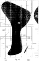
- This can result in a card 1, for example, as shown in detail in FIG.
- the solid lines show the tramlines 2, the intervals at which they are created and the intervals at which the field is to be driven through, in order to ensure an exact connection.
- the lightly shaded area 4 represents an area with a lower nutrient supply than the base area 3, while the darker shaded areas 5 have a higher nutrient supply than the base area 3.
- the areas shaded in the same way thus have a similar or the same nutrient supply.
- the field shown in FIG. 1 in the partial area is stored in a computer 6, the position of the tramlines 2 and the partial areas 3, 4, 5 being stored in terms of location or coordinates.
- a tractor 7 with a centrifugal fertilizer spreader 8 is provided.
- the centrifugal fertilizer spreader 8 is attached to the agricultural tractor 7 via the three-point clutch 9.
- the centrifugal fertilizer spreader 8 has the storage container 10 and the frame 11.
- the centrifugal disks 12, to which the material located in the storage container 10 is fed via a metering device, are arranged below the storage container 10.
- the metering device assigned to each centrifugal disc 12 can be set independently of the other.
- the on-board computer 6 is arranged on the tractor 7.
- this computer station which is designed as an on-board computer 6, a chip card is provided via suitable input devices, such as a keyboard, for example is supplied with the appropriate data via a computer available on the farm, the data about the field and the distribution machine to enter and save. So the ground map, the distribution of the material and the setting of the fertilizer spreader are entered in this computer station, as calculated by the computer on the farm according to a program.
- the computer station 2 is equipped with a GPS system or a DGPS system (Digital Global Position System) 13.
- This system 13 works with satellite support, so that the current location of the tractor 7 or the distribution machine 7 on the field can be determined accordingly.
- the distribution machine 8 is controlled on the basis of this location-determined data in accordance with the floor map 1 and data entered in the computer.
- the fertilizer is spread in a uniform distribution, as represented by the spreading pattern (spreading material distribution) 15, because there is an equal supply of nutrients over the entire spreading and working width.
- the tractor 7 with the distribution machine 8 is located in the area 5 in which the soil is undersupplied. This means that in comparison to area 3, which is highlighted in white, more fertilizer is applied, as can be seen from a comparison with the spread pattern 16.
- the fertilizer is distributed according to the distribution as shown in the spreading pattern 19. Over the area 5, which has an undersupply, more fertilizer is applied, as in the area 4, which has an oversupply. If the centrifugal fertilizer spreader 8 is located at the point 20, more fertilizer is applied in the area 5 in which there is an undersupply than in the area 3 which has a basic supply. The fertilizer is thus distributed in accordance with the distribution as shown in the spread pattern 21.
- a step-by-step or continuous change can be provided by the one distribution characteristic.
- the spread fan can also be taken into account. The control is thus practically based on a three-dimensional scatter pattern.
- the computer 6 continuously determines the specific location of the tractor or the distribution machine via the DGPS system 13, so that it is continuously determined at which point the tractor 6 with the distribution machine 8 is in the field and which nutrient supply at the current location prevails.
- the application rate is set on the basis of this data.
- the distributing machine 8 is able to dispense different amounts of material on the right and left, as shown in the individual scatter patterns 15, 16, 21, which is entered in the map section according to FIG.
- the spreading quantity of the fertilizer spreader 8 is adjusted continuously or at intervals in accordance with the predominant area-specific conditions during the spreading process by interpreting the area-specifically stored data of the area traveled.
- the application rate of the fertilizer spreader 8 is adjusted on one side in accordance with the predominant area-specific conditions per half working width. It is also possible to make adjustments in smaller sections than half the working width if the distributor is designed accordingly.
- the computer in conjunction with the DGPS system and the stored values corresponding to a soil quality or nutrient supply, as shown for example in Fig. 1, intelligently links the application rate actually applied with the actually given nutrient supply for the soil.
- the system can also be used to intelligently adjust the work cycle by switching the fertilizer spreaders and sprayers accordingly.
- a program is stored in the computer 6 so that, depending on the current driving speed, a pre-calculation is carried out at which point in time the distributor 8 is actually at or has reached the location at which the quantity of material specified there is being applied should. This switches off the so-called dead time.
- the program stored in the computer 6 is designed such that the implement 8 automatically switches on again when the tramline or the planned lane for an interruption in work, e.g. Refilling the storage container or the like, is left and started again for further work. This automatically ensures a seamless distribution of the fertilizer.
- the program in the on-board computer 6 is designed such that the on-board computer 6 calculates in advance, based on the planning of the material distribution, at which point it makes sense to refill the storage container 10. This avoids unnecessary empty runs and double runs within the field.
- 5 shows a further control of the distribution of the fertilizer transversely to the direction of travel of the fertilizer spreader 8.
- a specific adjustment of the distribution of the material according to the area-specific conditions during the Spreading process carried out by interpreting the area-specific stored data of the area traveled.
- more material is applied in accordance with the scatter pattern 23. This is possible, for example, by changing the point of application of the fertilizer on the centrifugal discs. This can also be made possible, for example, by changing the blade setting, which is carried out via a remote control device.
- the application rate is reduced in the central area 25 because only a basic supply of the soil with mineral fertilizer is required, while in the area areas 5 a higher fertilizer distribution is required due to the lower nutrient supply to the soil.
- the system according to the invention can, if necessary, not only the scatter pattern, i.e. the fertilizer distribution, but also the spread of the spreading fan in a centrifugal fertilizer spreader.
- the predefined route is stored in the computer 6, which on the monitor 26 of the computer 6 corresponds to the lines 27 which, for example can correspond to the tramlines 2 is shown. Furthermore, the current location of the vehicle 7 on the field is displayed on the monitor 26. If it is now shown as is symbolized by the cross 28 that the tractor is in the intended lane 27, the tractor driver will follow this lane 27. However, if it is now indicated that the tractor 7 is to the right or left of the tramline lane 27, the tractor driver must correct his travel path such that it is again in the lane 27, as represented by the cross 28.
- the correct adherence to the route can be represented, for example, with a green illuminated dot and the deviation from the route with a red illuminated dot.
- the above-described distribution of material can be applied to centrifugal fertilizer spreaders, field sprayers, seeders etc.
- the map in accordance with FIG. 1 it can be stored in the computer at which point the seed is to be deposited at what depth in the soil by sowing coulters.
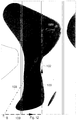
- FIG. 7 shows the coulter 29 of a distribution machine designed as a seed drill, which is arranged on a frame 30.
- the coulter 29 is arranged to be movable in an upright plane on the frame 30 by means of the joint 31.
- the tension spring 33 of a coulter pressure adjusting device 34 is arranged on the arm 32 of the coulter 29 which projects forward.
- the coulter pressure can be set and changed via the hydraulic cylinder 35 and the control unit 36, which is controlled by the computer 6 via the cable 37.
- At least one coulter 29 is equipped with a distance measuring device 38 in order to be able to determine the placement depth of the seed 39 in the soil 40 after a calibration process. The determined distance data are transmitted to the computer 6 via the control unit 36.
- the desired storage depth in the individual partial areas of the field can be stored in the on-board computer analogously to the entry of the nutrient supply or in its place.
- the area 3 with a white background can be provided with a base placement depth of, for example, 4 cm, for the area 4, with a placement depth of 3 cm and for the areas 5 with a placement depth of 5 cm.
- the coulter pressure is regulated accordingly when the machine is at the respective locations.
- the determination of the location where the seeder is located is via the DGPS system determined. This means that the seed placement depth is specified for each location. Based on the entered values, a surface-specific adjustment of the coulter pressure is carried out in accordance with the site-specific conditions in order to achieve the seed placement depth.
- FIG. 8 shows an order combination consisting of a fertilizer spreader 41 with the fertilizer coulter 42, the precision seed drill 43 and the microgranular spreader 44.
- the fertilizer spreader 41 has the metering device 45, via which the fertilizer located in the storage container 46 is supplied in adjustable amounts to the fertilizer coulters 42, via which it is deposited in the ground.
- the precision seed drill 43 has the storage container 47, the metering device 48 and the coulter 49.
- the seed is deposited in the soil in predetermined amounts via the metering device 48.
- a microgranule spreader 44 which has a metering device 50, via which the granules located in the storage container 51 are discharged in adjustable amounts via the discharge lines 52.
- the setting elements of the metering devices 45, 48 and 49 are connected to the computer.
- a program is entered in the computer 6 in accordance with the area-specific conditions, such as can be stored in accordance with a map in accordance with FIG. 1.
- an individual regulation of the application rates of the different application and distribution machines is possible independently of the sowing amounts of the other machine, so that an area-specific adjustment of the application rate can be achieved.
- the current location of the order combination is determined by the DGPS system.
- a distribution machine is equipped with a tramline circuit, this is also switched by the computer 6, so that it is ensured in a predetermined manner that the tramlines are created in the correct place on the field in the correct rhythm. If such a machine is equipped with a pre-emergence marking, it is also actuated by the computer 6 in a predetermined rhythm depending on the tramline switching.
- the specific properties such as, for example, are first placed in a soil map Nutrient supply, soil strength and / or soil type etc. entered. This results, for example, in an application card 101, as shown in detail in FIG.
- the solid lines show the tramlines 102, the intervals at which they are created and the intervals at which the field is to be driven through, in order to ensure an exact connection.
- the lightly shaded area 104 represents an area with a lower nutrient supply compared to the base area 103, while the darker shaded areas 105 have a higher nutrient supply than the base area 3.
- the areas shaded in the same way thus have a similar or the same nutrient supply.
- a grid 106 is placed over the map according to FIG. 10.
- the surfaces 103, 104, 105 are then determined in accordance with the distribution characteristic and the soil properties in accordance with FIG. 11 shows the rastered application card 107 of the card 101 according to FIG. 9.
- a work file is created on the basis of the rasterized application card 107 and the machine-specific distribution characteristic of the distribution machine used in each case.
- This work file represents an optimal adaptation between the application card 107 and the distribution characteristic of the distribution machine used.
- the metering elements of the distribution machine are then controlled or regulated in accordance with the work file, so that the material to be distributed is distributed in the desired manner.
- the grid 106 is advantageously applied in the direction of the tramlines 102, as is shown in FIGS. 10 and 11.
- the dosing member on the headlands is automatically switched off on the basis of the position transmitter for generating field coordinate signals (GPS) in connection with the stored field data (application card 107).
- GPS field coordinate signals
- sensors such as radar sensors, steering angle sensors or wheel sensors (measuring the distance) are provided on the computer to increase the accuracy of the GPS signals.
- FIG. 12 shows the map according to FIG. 9, in which, for example, a soil sample is to be taken at point A.
- a direction finder By means of a direction finder, the shortest way can be traveled from the starting point B to the point A, as this is represented by the line 108.
- this has disadvantages if seeds have already been sown in the field. This method will be used when the field is harvested or in a meadow when there is no consideration for the vegetation.
- the route 109 will be driven using the tramlines to get to point A for a sample.
- a map of the field with the tramlines 102 created is stored in the computer, that the computer displays the shortest route using the tramlines 102 to the predetermined point A for sampling in the field, in particular calculates it and / or printed.
- a corresponding display or other suitable display devices are then provided on the computer.
Abstract
Description
Die Erfindung betrifft ein Verfahren gemäß des Oberbegriffes des Patentanspruches 1.The invention relates to a method according to the preamble of
In der Landwirtschaft sind verschiedene Verfahren zum Steuern und/oder Regeln von landwirtschaftlichen Bearbeitungs- und/oder Verteilmaschinen bekannt, die sich zur momentanen Positionsermittlung der Maschine auf dem Feld auf das sogenannte DGPS (Differential Global Position System) stützen. Bei diesem Verfahren sind Rechner vorgesehen, in welchem maschinenspezifische Daten zur Erstellung der Maschine je Standort und Fläche eingespeichert sind.In agriculture, various methods for controlling and / or regulating agricultural processing and / or distributing machines are known, which are based on the so-called DGPS (Differential Global Position System) for the current determination of the position of the machine in the field. In this method, computers are provided in which machine-specific data for creating the machine are stored per location and area.
Der Erfindung liegt die Aufgabe zugrunde, eine möglichst genaue teilschlagspezifische Bewirtschaftung bei der Ausbringung von Saatgut, Düngemitteln und Pflanzenschutzmitteln zu erreichen.The invention has for its object to achieve the most accurate possible partial crop management in the application of seeds, fertilizers and crop protection agents.
Diese Aufgabe wird in einer Ausführungsform erfindungsgemäß durch die kennzeichnenden Maßnahmen des Anspruches 1 gelöst. Infolge dieser Maßnahmen wird eine sehr genaue Bearbeitung der Fläche bzw. eine sehr genaue Verteilung des auszubringenden Materials an die Gegebenheiten der jeweiligen Teilflächen des Feldes erreicht. Der Rechner erkennt aufgrund des Positionsgebers (DGPS), an welcher Stelle er sich auf dem Feld befindet. In Abhängigkeit der eingespeicherten maschinenspezifischen Daten zur Einstellung der Maschine je Standort und Fläche wird ein individuelle Bearbeitung der Fläche bzw. Verteilung des Materials auf der Fläche erreicht.In one embodiment, this object is achieved according to the invention by the characterizing measures of
So ist es bei einer landwirtschaftlichen Maschine, die als Drill- oder Sämaschine ausgebildet ist, entsprechend des Anspruches 2 möglich, eine standortspezifische Saatgutablagetiefe zu gewährleisten, so daß das Saatgut in der aufgrund des Standortes vorherrschenden Bedingungen in optimaler Tiefe abgelegt wird. Hierzu wird dann der Schardruck zur Erreichung der Saatgutablagetiefe entsprechend angepaßt. Diese Anpassung kann automatisch oder von Hand entsprechend einer Anzeigevorrichtung erfolgen.So it is possible with an agricultural machine, which is designed as a drill or seeder, to ensure a location-specific seed placement depth, so that the seed is deposited at the optimum depth in the conditions prevailing due to the location. For this the coulter pressure is then adjusted accordingly to achieve the seed placement depth. This adjustment can take place automatically or by hand in accordance with a display device.
Desweiteren ist bei einer Verteilmaschine, die als Sämaschine ausgebildet ist und eine Fahrgasseneinrichtung aufweist, gemäß des Anspruches 3 vorgesehen, daß die Schalteinrichtung für die Fahrgasseneinrichtung von dem Rechner aufgrund der von dem Positionsgeber ermittelten Standortdaten geschaltet wird. Hierbei ist in dem Rechner eingespeichert, an welcher Stelle auf dem Feld eine Fahrgasse angelegt werden soll. Wenn diese Stelle auf dem Feld erreicht wird, wird durch den Rechner aufgrund der von dem Positionsgeber ermittelten Standortdaten die Schaltvorrichtung für die Fahrgasseneinrichtung betätigt, so daß die Fahrgasse jeweils auch an der richtigen Stelle angelegt wird. Ein falscher Fahrgassenrhytmus, wie er in der Vergangenheit in der Praxis aufgrund von Fehlbedienungen vorkommen konnte, wird somit sicher vermieden. Falls eine Sämaschine mit einer Vorauflaufmarkierung ausgestattet ist, wird diese in Abhängigkeit von dem Anlegen der Fahrgasse von der Schalteinrichtung, die von dem Rechner aufgrund der von dem Positionsgeber ermittelten Daten geschaltet wird, mit umgeschaltet.Furthermore, it is provided in a distributor, which is designed as a seeder and has a tramline device, that the switching device for the tramline device is switched by the computer on the basis of the location data determined by the position transmitter. The computer stores the location at which a tramline should be created in the field. When this point in the field is reached, the switching device for the tramline device is actuated by the computer on the basis of the location data determined by the position transmitter, so that the tramline is also created at the correct point. An incorrect tramline rhythm, which could have occurred in practice in the past due to incorrect operation, is thus reliably avoided. If a seed drill is equipped with a pre-emergence marking, this is switched over depending on the creation of the tramline by the switching device, which is switched by the computer on the basis of the data determined by the position transmitter.
Bei einer Verteilmaschine, die als Sä- oder Einzelkornsämaschine ausgebildet ist, wird erfindungsgemäß die Aussaatmenge der Sä- oder Einzelkornsämaschine je Standort eingestellt.In the case of a distribution machine which is designed as a sowing or precision seed drill, the sowing quantity of the sowing or precision seed drill is set according to the invention.
Bei einer Verteilmaschine, die aus einer Einzelkornsämaschine mit einem Düngerstreuer und einem Mikrogranulatstreuer besteht, ist gemäß des Anspruches 6 vorgesehen, daß eine individuelle Regelung der Ausbringmenge des Düngerstreuers und/oder der Granulatmengen derart erfolgt, daß eine flächenspezifische Anpassung der Ausbringmengen der verschiedenen Ausbring-und Verteilmaschinen unabhängig von den Aussaatmengen der jeweils anderen Maschine erfolgt. Somit ist also eine individuelle Regelung der Ausbringmengen der Materialien für die Unterfußdüngung und des Mikrogranulataustrages möglich. Somit kann also individuell jedes auszubringende Material den flächenspezifischen Gegebenheiten individuell angepaßt werden.In a distributor that consists of a precision seed drill with a fertilizer spreader and a microgranular spreader, it is provided according to claim 6 that the spreading rate of the fertilizer spreader and / or the amount of granulate is regulated individually in such a way that an area-specific adjustment of the spreading rates of the different spreading rates and Distribution machines regardless of the sowing rates of the other machine. An individual regulation of the application rates of the materials for the underfoot fertilization and the microgranulate discharge is possible. Thus, each material to be applied can be individually adapted to the area-specific conditions.
Desweiteren ist erfindungsgemäß vorgesehen, daß ein laufendes und/oder intervallweises spezifisches Anpassen der Ausbringmengen der jeweiligen Verteilmaschine, wie Düngerstreuer, Feldspritze, Drillmaschine entsprechend den überwiegenden flächenspezifischen Gegebenheiten während des Ausbringvorganges durch eine Interpretation der flächenspezifischen abgespeicherten Daten der befahrenen Fläche erfolgt. Infolge dieser Maßnahmen wird eine möglichst genaue Anpassung der Ausbringmenge entsprechend der vorhandenen Nährstoffversorgung des Bodens erreicht. Somit kann also vorab festgelegt werden, welche jeweilige Ausbringmenge von Saatgut, Düngemitteln oder Pflanzenschutzmitteln an der jeweiligen Stelle der zu bearbeitenden Fläche ausgebracht werden soll. Entsprechend dieser Festlegung erfolgt dann die Einstellung der Dosierorgane der Verteilmaschinen, um eine entsprechende Ausbringung der Materialien zu gewährleisten.Furthermore, it is provided according to the invention that a continuous and / or interval-specific adaptation of the application rates of the respective distribution machine, such as fertilizer spreader, field sprayer, and seed drill, in accordance with the predominant area-specific conditions during the Spreading process is carried out by an interpretation of the area-specific stored data of the area traveled. As a result of these measures, the application rate is adjusted as precisely as possible in accordance with the existing nutrient supply to the soil. Thus, it can be determined in advance which application rate of seed, fertilizer or crop protection agent is to be applied at the respective point on the area to be worked. In accordance with this definition, the metering elements of the distribution machines are then adjusted in order to ensure a corresponding output of the materials.
Desweiteren ist vorgesehen, daß eine laufende und/oder spezifische Anpassung der Verteilung des Materials durch die Verteilmaschine entsprechend den flächenspezifischen Gegebenheiten während des Ausbringvorganges durch die Interpretation der flächenspezifischen, abgespeicherten Daten der befahrenen Fläche erfolgt. So wird nicht nur eine Veränderung der Ausbringmenge in Abhängigkeit des gefahrenen Weges über die gesamte Arbeitsbreite ermöglicht, sondern es kann die Verteilung innerhalb der Arbeitsbreite entsprechend der überfahrenen Teilflächen angepaßt werden.Furthermore, it is provided that a continuous and / or specific adjustment of the distribution of the material by the distribution machine takes place in accordance with the area-specific conditions during the application process by interpreting the area-specific, stored data of the area traveled. This not only enables a change in the spread rate depending on the distance traveled over the entire working width, but the distribution within the working width can be adjusted according to the partial areas covered.
Hierbei kann vorgesehen sein, daß ein halbseitiges- oder teilbreitenspezifisches Anpassen der Ausbringmengen der Verteilmaschine entsprechend den überwiegenden flächenspezifischen Gegebenheiten je ganzer oder halber Arbeits-oder Teilbreite erfolgt.It can be provided here that the spreading quantities of the distributing machine are adapted to one side or part of a width in accordance with the predominant surface-specific conditions for the entire or half of the working or part width.
Desweiteren ist erfindungsgemäß nach Anspruch 11 vorgesehen, daß mittels einer geeigneten Anzeigevorrichtung das Einhalten der vorgesehen Fahrspur zum Einhalten der Fahrabstände zu der vorhergehenden Fahrspur angezeigt bzw. die Fahrspur und/oder die Fahrspuren angezeigt werden. Dieses ist vor allem beim Befahren von Flächen, bei denen Orientierungshilfen, wie beispielsweise Fahrgassen fehlen, wie dieses beispielsweise beim Düngen auf Grünland der Fall ist, für das genaue Anschlußfahren von großer Bedeutung.Furthermore, according to the invention it is provided according to
Um eine möglichst genaue und exakte Anpassung der Ausbringmengen zu erreichen, ist gemäß des Anspruches 12 vorgesehen, daß der Rechner in Abhängigkeit der aktuellen Fahrgeschwindigkeit eine Vorausberechnung durchführt, zu welchem Zeitpunkt die Verteilmaschine tatsächlich an dem Standort sich befindet bzw. diesen erreicht hat, an dem die jeweils dort festgelegte Menge Material ausgebracht werden soll.In order to achieve the most accurate and exact possible adjustment of the application rates, it is provided according to
Desweiteren ist erfindungsgemäß vorgesehen, daß sich das Arbeitsgerät automatisch wieder einschaltet, wenn die Fahrgasse oder die geplante Fahrspur für eine Arbeitsunterbrechung - z.B. zum Nachfüllen des Vorratsbehälters o.ä. - verlassen wird und für die Weiterarbeit wieder angefahren wird. Somit wird also die Arbeit oder das Ausbringen von Material automatisch an der richtigen Stelle, an der die Arbeit unterbrochen worden ist, wieder fortgesetzt, ohne daß Doppel-oder Fehlbearbeitung entsteht.Furthermore, it is provided according to the invention that the implement automatically switches on again when the tramline or the planned lane for an interruption in work - e.g. for refilling the storage container or similar - is left and started again for further work. Thus, the work or the application of material is automatically continued at the correct point at which the work was interrupted, without duplicate or incorrect processing.
Weiterhin ist erfindungsgemäß vorgesehen, daß der Bordcomputer aufgrund der Planung vorausberechnet, an welcher Stelle es sinnvoll ist, den Vorratsbehälter aufzufüllen. Somit wird eine Optimierung der Arbeitsweise erreicht.Furthermore, it is provided according to the invention that the on-board computer uses the planning to calculate in advance at which point it makes sense to fill up the storage container. This optimizes the way of working.
Um weiterhin auf einfache Weise die Datenmenge, die in dem Rechner einzuspeichern ist, erheblich zu reduzieren, wobei jedoch eine ausreichend genaue Ausbringung gewährleistet bleibt, sind die kennzeichnenden Merkmale des Patentanspruches 15 vorgesehen. Infolge dieser Maßnahmen werden die Karten gerastert, so daß die Datenmenge begrenzt und somit erheblich gegenüber dem bekannten Verfahren reduziert wird. Bei der Rasterung akzeptiert man eine gewisse Ungenauigkeit, wobei das Ergebnis jedoch noch ausreichend genau, im Hinblick auf die zum Einsatz kommenden Maschinen und der Feld- und Bodeneigenschaften, ist. Somit werden also Arbeitsdateien zur optimalen Ansteuerung von Zentrifugaldüngerstreuern und anderen landwirtschaftlichen Maschinen unter Berücksichtigung von Verteilcharakteristiken im Bezug auf Applikationskarten erstellt.In order to further reduce the amount of data that is to be stored in the computer in a simple manner, while ensuring a sufficiently precise output, the characterizing features of
Weiterhin ist erfindungsgemäß vorgesehen, daß aufgrund der gerasterten Applikationskarte und der maschinenspezifischen Charakteristik eine Arbeitsdatei erstellt wird, und daß diese Arbeitsdatei eine optimale Anpassung zwischen Applikationskarte und Verteilcharakteristik darstellt. Hierdurch ergibt sich eine möglichst genaue Ausbringung des Materials entsprechend der Bodenbeschaffenheit und Bodenversorgung an Nährstoffen etc.. Eine besonders gute Abstimmung zwischen Applikationskarte und Verteilcharakteristik der Verteilmaschine wird dadurch erreicht, daß die Rasterung in Richtung der Fahrgasse bzw. in Richtung der Fahrtrichtung der Verteilmaschine angelegt wird.Furthermore, it is provided according to the invention that a work file is created on the basis of the rasterized application card and the machine-specific characteristics, and that this work file represents an optimal adaptation between the application card and the distribution characteristic. This results in the most accurate possible application of the material according to the nature of the soil and soil supply of nutrients etc. A particularly good match between the application map and the distribution characteristics of the distributor is achieved in that the grid is applied in the direction of the tramline or in the direction of travel of the distributor .
Zusammenfassend wird also folgender Grundgedanke verfolgt:In summary, the following basic idea is pursued:
Bei einer flächenspezifischen Bewirtschaftung werden für eine angepaßte Düngerabgabe unter der Hinzunahme von Bodenproben, Ertragskarten, Klimadaten usw. Appliationskarten erstellt. Diese Karten werden dann gerastert, um die Datenmenge zu begrenzen. Bei der Rasterung akzeptiert man eine gewisse Ungenauigkeit. Bedingt durch den dreidimensionalen Streufächer eines Schleuderstreuers ist eine genau der Rasterung entsprechende Ausbringung des Streugutes nicht möglich. In dem Bordcomputer wird eine Arbeitsdatei hinterlegt, so daß sich eine optimale Anpassung zwischen Applikationskarte und Verteilcharakteristik beim Düngen, beispielsweise mit einem Schleuderstreuer ergibt.In the case of area-specific cultivation, application maps are created for an adapted fertilizer delivery with the addition of soil samples, yield maps, climate data etc. These maps are then rasterized to limit the amount of data. A certain degree of inaccuracy is accepted when screening. Due to the three-dimensional spreading fan of a centrifugal spreader, it is not possible to spread the spreading material exactly according to the grid. A work file is stored in the on-board computer, so that there is an optimal adaptation between the application map and the distribution characteristic when fertilizing, for example with a centrifugal spreader.
Weitere Einzelheiten der Erfindung sind den übrigen Unteransprüchen, der Beispielsbeschreibung und den Zeichnungen zu entnehmen. Hierbei zeigen
- Fig.1
- den Ausschnitt einer Bodenkarte eines Feldes,
- Fig.2
- eine an einen Ackerschlepper angebaute als Schleuderdüngerstreuer ausgebildete Verteilmaschine in der Seitenansicht und in Prinzipdarstellung,
- Fig.3
- ein Standortbestimmungssystem in Prinzipdarstellung,
- Fig.4
- das Abstreuen eines Feldes mit einem Zentrifugaldüngerstreuer in Prinzipdarstellung nach der Bodenkarte gemäß Fig. 1,
- Fig.5
- ein weiteres Abstreuen eines Feldes in Prinzipdarstellung,
- Fig.6
- den Monitor eines Bordcomputers zum Befahren eines Feldes,
- Fig.7
- das Säschar einer Drillmaschine,
- Fig.8
- eine Bestellkombination in Seitenansicht und in Prinzipdarstellung,
- Fig.9
- den Ausschnitt einer Bodenkarte eines Feldes,
- Fig.10
- die Bodenkarte gemäß Fig.9 mit einem darüber gelegten Raster,
- Fig.11
- die Bodenkarte gemäß Fig.9, wobei die Flächenbereiche entsprechend des Rasters nach Fig.10 gerastert sind und
- Fig.12
- eine weitere Bodenkarte, auf welcher der optimale Fahrweg zur Entnahme einer Bodenprobe dargestellt ist.
- Fig. 1
- a section of a ground map of a field,
- Fig. 2
- a side view and a schematic representation of a spreading machine mounted on a tractor as a centrifugal fertilizer spreader,
- Fig. 3
- a location determination system in principle,
- Fig. 4
- the spreading of a field with a centrifugal fertilizer spreader in a basic representation according to the soil map according to FIG. 1,
- Fig. 5
- another spreading of a field in principle,
- Fig. 6
- the monitor of an on-board computer for driving in a field,
- Fig. 7
- the coulter of a seed drill,
- Fig. 8
- an order combination in side view and in principle,
- Fig. 9
- a section of a ground map of a field,
- Fig. 10
- 9 the bottom map according to FIG. 9 with a grid placed above it,
- Fig. 11
- the bottom map according to Figure 9, wherein the surface areas are rasterized according to the grid of Figure 10 and
- Fig. 12
- another soil map, on which the optimal route for taking a soil sample is shown.
Zur bedarfsgerechten Bewirtschaftung von Flächen werden zunächst in eine Bodenkarte die spezifischen Beschaffenheiten, wie beispielsweise Nährstoffversorgung, Bodenfestigkeit und/oder Bodenart etc. eingetragen. Hierdurch kann sich beispielsweise eine Karte 1 ergeben, wie sie in Fig.1 ausschnittsweise dargestellt ist. Mit den durchzogenen Linien sind die Fahrgassen 2 dargestellt, in welchen Abständen sie angelegt und in welchen Abständen das Feld durchfahren werden soll, um so ein genaues Anschlußfahren zu gewährleisten.For the needs-based management of areas, the specific properties, such as nutrient supply, soil strength and / or soil type, etc. are first entered in a soil map. This can result in a
Desweiteren sind verschiedene Teilflächen unterschiedlich schattiert dargestellt. Die weiß unterlegte Fläche 3 stellt die überwiegende Beschaffenheit des Feldes, beispielsweise die Basisbeschaffenheit dieses Feldes dar.Furthermore, different partial areas are shown differently shaded. The
Die hell schattierte Fläche 4 stellt einen Bereich mit einer gegenüber der Basisfläche 3 niedrigeren Nährstoffversorgung dar, während die dunkler schattierten Flächen 5 eine höhere Nährstoffversorgung als die Basisfläche 3 aufweisen. Die in gleicher weise schattierten Flächen weisen also eine ähnliche oder gleiche Nährstoffversorgung auf.The lightly shaded
Das gemäß Fig.1 im Teilbereich dargestellte Feld ist in einem Rechner 6 abgespeichert, wobei die Lage der Fahrgassen 2 und die Teilflächen 3, 4, 5 standort- bzw. koordinatenmäßig abgespeichert sind.The field shown in FIG. 1 in the partial area is stored in a computer 6, the position of the
Um auf dem Feld Mineraldünger zu verteilen, ist ein Ackerschlepper 7 mit einem Zentrifugaldüngerstreuer 8 gemäß Fig.2 vorgesehen. An dem Ackerschlepper 7 ist über die Dreipunktkupplung 9 der Zentrifugaldüngerstreuer 8 angebaut. Der Zentrifugaldüngerstreuer 8 weist den Vorratsbehälter 10 und den Rahmen 11 auf. Unterhalb des Vorratsbehälters 10 sind die Schleuderscheiben 12 angeordnet, denen das sich im Vorratsbehälter 10 befindliche Material über eine Dosiereinrichtung zugeführt wird. Die jeder Schleuderscheibe 12 zugeordnete Dosiereinrichtung ist unabhängig von der anderen einstellbar.In order to distribute mineral fertilizers in the field, a
Auf dem Ackerschlepper 7 ist der Bordrechner 6 angeordnet. In dieser als Bordrechner 6 ausgebildeten Rechnerstation sind über geeignete Eingabevorrichtungen, wie beispielsweise eine Tastatur, eine Chipkarte, welche über einen auf dem Hof vorhandenen Rechner mit entsprechenden Daten versorgt ist, die Daten über das Feld sowie der Verteilmaschine einzugeben und zu speichern. So sind in dieser Rechnerstation die Bodenkarte, die Verteilung des Materials und die Einstellung des Düngerstreuers eingegeben, wie sie von dem Rechner auf dem Hof entsprechend eines Programmes berechnet worden sind.The on-board computer 6 is arranged on the
Desweiteren ist die Rechnerstation 2 mit einem GPS-System oder einem DGPS-System (Digital Global Position System) 13 ausgestattet. Dieses System 13 arbeitet sattelitengestützt, so daß der aktuelle Standort des Schleppers 7 bzw. der Verteilmaschine 7 auf dem Acker entsprechend genau zu bestimmen ist. Anhand dieser standortermittelten Daten wird die Verteilmaschine 8 entsprechend der in dem Rechner eingegebenen Bodenkarte 1 und Daten gesteuert.Furthermore, the
Dieses soll anhand der Bodenkarten gemäß Fig.4 und 5 näher erläutert werden.This will be explained in more detail with the aid of the soil maps according to FIGS. 4 and 5.
Wenn der Schlepper 7 mit der Verteilmaschine 8 sich an der Stelle 14 befindet, wird der Dünger in gleichmäßiger Verteilung, wie dieses durch das Streubild (Streugutverteilung) 15 dargestellt ist, ausgebracht, weil über die gesamte Verteil-und Arbeitsbreite eine gleiche Nährstoffversorgung herrscht. Der Schlepper 7 mit der Verteilmaschine 8 befindet sich in dem Bereich 5, in welchem der Boden unterversorgt ist. Dieses bedeutet also, daß im Vergleich zu dem Bereich 3, welcher weiß unterlegt ist, mehr Dünger ausgebracht wird, wie dieses ein Vergleich mit dem Streubild 16 zu sehen ist. Die Verteilmaschine 8, die sich an der Stelle 17 in einem Bereich der Basisversorgung befindet, verteilt den Dünger wie es in dem Streubild 16 dargestellt ist.When the
Wenn der Schlepper 7 mit der Verteilmaschine 8 in den Bereich 18 kommt, wird der Dünger gemäß der Verteilung, wie sie in dem Streubild 19 dargestellt ist, verteilt. Über den Bereich 5, der eine Unterversorgung aufweist, wird mehr Dünger ausgebracht, wie in dem Bereich 4, der eine Überversorgung aufweist. Wenn der Schleuderdüngerstreuer 8 sich an der Stelle 20 befindet, wird in dem Flächenbereich 5, in dem ein Unterversorgung herrscht, mehr Dünger ausgebracht, als in dem Bereich 3, der eine Basisversorgung aufweist. Der Dünger wird also gemäß der Verteilung, wie sie in dem Streubild 21 dargestellt ist, verteilt. Der Übergang von der einen Verteilcharakteristik zu der anderen, d.h. bei dem Überfahren verschiedener Nährstoffversorgungsbereiche oder dem Wechsel von einem Bereich in einem anderen erfolgt die Verteilung, wie sie in den Streubildern dargestellt ist, bzw. deren Übergang entsprechend der Vorgabe des Rechners.When the
Hierbei kann eine stufen- oder kontinuierlich laufende Veränderung (Übergangsbereiche werden berücksichtigt) von der einen Verteilcharakteristik vorgesehen sein. Neben der Verteilcharakteristik (Streubild) kann auch der Streufächer berücksichtigt werden. Somit erfolgt die Regelung quasi nach einem dreidimensionalen Streubild.A step-by-step or continuous change (transition areas are taken into account) can be provided by the one distribution characteristic. In addition to the distribution characteristics (spread pattern), the spread fan can also be taken into account. The control is thus practically based on a three-dimensional scatter pattern.
Der Rechner 6 ermittelt über das DGPS-System 13 laufend den spezifischen Standort des Schleppers bzw. der Verteilmaschine, so daß laufend festgestellt wird, an welcher Stelle der Schlepper 6 mit der Verteilmaschine 8 auf dem Acker sich befindet und welche Nährstoffversorgung an dem jeweils aktuellen Standort herrscht. Anhand dieser Daten wird die Ausbringmenge eingestellt. Die Verteilmaschine 8 ist in der Lage rechts und links verschiedene Mengen Material auszubringen, wie dieses in den einzelnen Streubildern 15, 16, 21, die in dem Kartenausschnitt gemäß Fig.4 eingetragen ist, dargestellt ist.The computer 6 continuously determines the specific location of the tractor or the distribution machine via the
Somit erfolgt ein laufendes bzw. intervallweises spezifisches Anpassen der Ausbringmenge des Düngerstreuers 8 entsprechend den überwiegenden flächenspezifischen Gegebenheiten während des Ausbringvorganges durch eine Interpretation der flächenspezifisch abgespeicherten Daten der befahrenen Fläche. Hierbei erfolgt gemäß dem Ausführungsbeispiel gemäß Fig.4 ein halbseitiges Anpassen der Ausbringmenge des Düngerstreuers 8 entsprechend den überwiegenden flächenspezifischen Gegebenheiten je halber Arbeitsbreite. Auch ist es möglich in kleineren Teilbreiten als halbe Arbeitsbreite eine Anpassung vorzunehmen, wenn die Verteilmaschine entsprechend ausgebildet ist. Es erfolgt also über den Rechner in Verbindung mit dem DGPS-System und den abgespeicherten Werten entsprechend einer Bodenbeschaffenheits- oder Nährstoffversorgungsheit, wie sie beispielsweise in Fig.1 dargestellt ist, eine intellegente Verknüpfung der tatsächlich ausgebrachten Ausbringmenge mit der tatsächlich gegebenen Nährstoffversorgung des Bodens. Auch kann eine intellegente Anpassung der Arbeitsreite durch entsprechendes Schalten bei Düngerstreuern und Feldspritzen mit diesem System erfolgen.Thus, the spreading quantity of the fertilizer spreader 8 is adjusted continuously or at intervals in accordance with the predominant area-specific conditions during the spreading process by interpreting the area-specifically stored data of the area traveled. Here, according to the exemplary embodiment according to FIG. 4, the application rate of the fertilizer spreader 8 is adjusted on one side in accordance with the predominant area-specific conditions per half working width. It is also possible to make adjustments in smaller sections than half the working width if the distributor is designed accordingly. The computer, in conjunction with the DGPS system and the stored values corresponding to a soil quality or nutrient supply, as shown for example in Fig. 1, intelligently links the application rate actually applied with the actually given nutrient supply for the soil. The system can also be used to intelligently adjust the work cycle by switching the fertilizer spreaders and sprayers accordingly.
Desweiteren ist in dem Rechner 6 ein Programm abgespeichert, so daß in Abhängigkeit der aktuellen Fahrgeschwindigkeit einer Vorausberechnung durchgeführt wird, zu welchem Zeitpunkt die Verteilmaschine 8 tatsächlich an dem Standort sich befindet bzw. diesen erreicht hat, an dem die jeweils dort festgelegte Menge Material ausgebracht werden soll. Hierdurch wird die sog. Totzeit ausgeschaltet.Furthermore, a program is stored in the computer 6 so that, depending on the current driving speed, a pre-calculation is carried out at which point in time the distributor 8 is actually at or has reached the location at which the quantity of material specified there is being applied should. This switches off the so-called dead time.
Desweiteren ist das in dem Rechner 6 abgespeicherte Programm derart ausgelegt, daß sich das Arbeitsgerät 8 automatisch wieder einschaltet, wenn die Fahrgasse oder die geplante Fahrspur für eine Arbeitsunterbrechung, z.B. Nachfüllen des Vorratsbehälters o.ä., verlassen wird und für die Weiterarbeit wieder angefahren wird. Hierdurch wird automatisch ein nahtloses Verteilen des Düngers erreicht. Um zu verhindern, daß innerhalb einer Arbeitsbahn der Vorratsbehälter 10 nachgefüllt werden muß, ist das Programm in dem Bordcomputer 6 derart ausgelegt, daß der Bordcomputer 6 aufgrund der Planung der Materialverteilung vorausberechnet, an welcher Stelle es sinnvoll ist, den Vorratsbehälter 10 wieder aufzufüllen. Somit werden unnötige Leerfahrten und Doppelfahrten innerhalb des Feldes vermieden.Furthermore, the program stored in the computer 6 is designed such that the implement 8 automatically switches on again when the tramline or the planned lane for an interruption in work, e.g. Refilling the storage container or the like, is left and started again for further work. This automatically ensures a seamless distribution of the fertilizer. In order to prevent the
Die Fig.5 zeigt eine weitere Steuerung der Verteilung des Düngers quer zur Fahrtrichtung des Düngerstreuers 8. Wie insbesondere die Streubilder 15, 18, 19, 21, 23 erkennen lassen, wird so eine spezifische Anpassung der Verteilung des Materials entsprechend den flächenspezifischen Gegebenheiten während des Ausbringvorganges durch die Interpretation der flächenspezifischen abgespeicherten Daten der befahrenen Fläche durchgeführt. Wie zu erkennen ist, wird an der Stelle 22, an der ebenfalls eine Unterversorgung herrscht, mehr Material gemäß des Streubildes 23 ausgebracht. Dieses ist beispielsweise dadurch möglich, daß der Aufgabepunkt des Düngers auf die Schleuderscheiben verändert wird. Auch kann dieses beispielsweise durch eine Änderung der Schaufeleinstellung welche über eine Ferndbedienungseinrichtung durchgeführt wird, ermöglicht werden.5 shows a further control of the distribution of the fertilizer transversely to the direction of travel of the fertilizer spreader 8. As can be seen in particular from the
Bei der Darstellung der Düngerverteilung gemäß des Streubildes 24 erfolgt im mittleren Bereich 25 eine Reduzierung der Ausbringmenge, weil hier nur eine Basisversorgung des Bodens mit Mineraldünger erforderlich ist, während in den Flächenbereichen 5 eine höhere Düngerverteilung aufgrund der geringeren Nährstoffversorgung des Bodens erforderlich ist. Das erfindungsgemäße System kann erforderlichenfalls nicht nur das Streubild, d.h. die Düngerverteilung, berücksichtigen, sondern auch die Ausladung des Streufächers bei einem Zentrifugaldüngerstreuer.In the representation of the fertilizer distribution according to the
Um auf Flächen, wie beispielsweise Grünland, auf denen keine Fahrgassen 2 oder andere Orientierungshilfen angelegt sind, ein genaues Anschlußverfahren zu ermöglichen, ist in dem Rechner 6 der vorgegebene Fahrweg eingespeichert, der auf dem Monitor 26 des Rechners 6 entsprechend den Linien 27, die beispielsweise den Fahrgassen 2 entsprechen können, dargestellt wird. Desweiteren wird auf dem Monitor 26 der jeweilige aktuelle Standort des Fahrzeuges 7 auf dem Acker angezeigt. Wenn nun angezeigt wird, wie durch das Kreuz 28 symbollisiert ist, der Schlepper sich in der vorgesehenen Fahrspur 27 befindet, wird der Schlepperfahrer dieser Spur 27 folgen. Falls nun jedoch angezeigt wird, daß der Schlepper 7 sich rechts oder links neben der Fahrgassenspur 27 befindet, so muß der Schlepperfahrer seinen Fahrweg derart korrigieren, daß er sich wieder, wie durch das Kreuz 28 dargestellt ist, in der Spur 27 befindet. Das korrekte Einhalten des Fahrwegs kann beispielsweise mit einem grünen Leuchtpunkt und das Abweichen von dem Fahrweg mit einem roten Leuchtpunkt dargestellt werden.In order to enable an exact connection method on areas such as grassland, on which no
Das vorbeschriebene Verteilen von Material kann sowohl bei Schleuderdüngerstreuern, Feldspritzen, Sämaschinen etc. angewendet werden.The above-described distribution of material can be applied to centrifugal fertilizer spreaders, field sprayers, seeders etc.
Desweiteren kann nach der Karte gemäß Fig.1 in dem Rechner abgespeichert werden, an welcher Stelle das Saatgut in welcher Tiefe im Boden durch Säschare abgelegt werden soll.Furthermore, according to the map in accordance with FIG. 1, it can be stored in the computer at which point the seed is to be deposited at what depth in the soil by sowing coulters.
Die Fig.7 zeigt das Säschar 29 einer als Sämaschine ausgebildeten Verteilmaschine, welches an einem Rahmen 30 angeordnet ist. Das Säschar 29 ist mittels des Gelenkes 31 an dem Rahmen 30 in aufrechter Ebene bewegbar angeordnet. Desweiteren ist an dem nach vorne ragenden Arm 32 des Säschares 29 die Zugfeder 33 einer Schardruckeinstelleinrichtung 34 angeordnet. Der Schardruck kann über den Hydraulikzylinder 35 und der Steuereinheit 36, die von dem Rechner 6 über das Kabel 37 angesteuert wird, eingestellt und verändert werden. Zumindest ein Säschar 29 ist mit einer Abstandsmeßeinrichtung 38 ausgerüstet, um so nach einem Eichvorgang die Ablagetiefe des Saatgutes 39 im Boden 40 ermitteln zu können. Die ermittelten Abstandsdaten werden über die Steuereinheit 36 an den Rechnern 6 übermittelt.7 shows the
Nach der Karte gemäß Fig. 1 kann analog zu der Eintragung der Nährstoffversorgung oder an deren Stelle die gewünschte Ablagetiefe in den einzelnen Teilflächen des Feldes in dem Bordrechner abgespeichert werden. Hierbei kann beispielsweise die weiß unterlegte Fläche 3 eine Basisablagetiefe von beispielsweise 4 cm, für die Fläche 4, in einer Ablagetiefe von 3 cm und für die Flächen 5 eine Ablagetiefe von 5 cm vorgesehen sein. Der Schardruck wird dann entsprechend geregelt, wenn die Maschine sich an den jeweiligen Orten befindet. Die Feststellung des Ortes, an dem sich die Sämaschine befindet, wird über das DGPS-System ermittelt. Somit wird standortspezifisch die Saatablagetiefe vorgegeben. Anhand der eingegebenen Werte erfolgt entsprechend den standortspezifischen Gegebenheiten eine flächenspezifische Anpassung des Schardruckes zur Erreichung der Saatgutablagetiefe.According to the map according to FIG. 1, the desired storage depth in the individual partial areas of the field can be stored in the on-board computer analogously to the entry of the nutrient supply or in its place. In this case, for example, the
Die Fig.8 zeigt eine Bestellkombination, bestehend aus einem Düngerstreuer 41 mit dem Düngersäschar 42, der Einzelkornsämaschine 43 und dem Mikrogranulatstreuer 44.8 shows an order combination consisting of a
Der Düngerstreuer 41 weist die Dosiereinrichtung 45 auf, über welche der sich in dem Vorratsbehälter 46 befindliche Dünger in einstellbaren Mengen den Düngersäscharen 42 zugeführt wird, über welche er im Boden abgelegt wird.The
Die Einzelkornsämaschine 43 weist den Vorratsbehälter 47, die Dosiereinrichtung 48 und das Säschar 49 auf. Über die Dosiereinrichtung 48 wird das Saatgut in vorbestimmten Mengen im Boden abgelegt.The
Desweiteren ist ein Mikrogranulatstreuer 44 vorgesehen, der eine Dosiereinrichtung 50 aufweist, über die das sich im Vorratsbehälter 51 befindliche Granulat über die Ausbringleitungen 52 in einstellbaren Mengen ausgebracht wird. Die Einstellorgane der Dosiereinrichtungen 45, 48 und 49 sind mit dem Rechner verbunden. In dem Rechner 6 ist ein Programm entsprechend den flächenspezifischen Gegebenheiten, wie sie entsprechend einer Karte gemäß Fig. 1 abgespeichert sein können, eingegeben. Hierbei ist eine individuelle Regelung der Ausbringmengen der verschiedenen Ausbring- und Verteilmaschinen unabhängig von den Aussaatmengen der jeweils anderen Maschine möglich, so daß eine flächenspezifische Anpassung der Ausbringmenge erreicht werden kann. Der aktuelle Standort der Bestellkombination wird durch das DGPS-System bestimmt.Furthermore, a
Wenn eine Verteilmaschine mit einer Fahrgassenschaltung ausgerüstet ist, wird diese ebenfalls von dem Rechner 6 geschaltet, so daß in vorgegebener Weise sichergestellt ist, daß die Fahrgassen an der richtigen Stelle auf dem Feld im richtigen Rythmus angelegt ist. Sollte eine derartige Maschine mit einer Vorauflaufmarkierung ausgerüstet sein, so wird sie ebenfalls von dem Rechner 6 im vorgegebenen Rythmus in Abhängigkeit der Fahrgassenschaltung betätigt.If a distribution machine is equipped with a tramline circuit, this is also switched by the computer 6, so that it is ensured in a predetermined manner that the tramlines are created in the correct place on the field in the correct rhythm. If such a machine is equipped with a pre-emergence marking, it is also actuated by the computer 6 in a predetermined rhythm depending on the tramline switching.
Zur bedarfsgerechten Bewirtschaftung von Flächen werden gemäß Fig. 9 zunächst in eine Bodenkarte die spezifischen Beschaffenheiten, wie beispielsweise Nährstoffversorgung, Bodenfestigkeit und/oder Bodenart etc. eingetragen. Hierdurch ergibt sich beispielsweise eine Applikationskarte 101, wie sie in Fig.9 ausschnittsweise dargestellt ist. Mit den durchzogenen Linien sind die Fahrgassen 102 dargestellt, in welchen Abständen sie angelegt und in welchen Abständen das Feld durchfahren werden soll, um so eine genaues Anschlußfahren zu gewährleisten.For the needs-based management of areas, according to FIG. 9, the specific properties, such as, for example, are first placed in a soil map Nutrient supply, soil strength and / or soil type etc. entered. This results, for example, in an
Desweiteren sind verschiedene Teilfächen unterschiedich schattiert dargestellt. Die weiß unterlegte Fläche 103 stellt die überwiegende Beschaffenheit des Feldes, beispielsweise die Basisbeschaffenheit dieses Feldes dar.Furthermore, different partial areas are shown differently shaded. The
Die hell schattierte Fläche 104 stellt einen Bereich mit einer gegenüber der Basisfläche 103 niedrigeren Nährstoffversorgung dar, während die dunkler schattierten Flächen 105 einen höheren Nährstoffversorgung als die Basisfläche 3 aufweisen. Die in gleicher Weise schattierten Flächen weisen also eine ähnliche oder gleiche Nährstoffversorgung auf.The lightly shaded
Um nun die Datenmenge zu begrenzen und eine einfachere, jedoch ausreichend genaue Steuerung der Ausbringmenge einer Verteilmaschine erreichen zu können, wird über die Karte gemäß Fig.9 ein Raster 106, wie dieses in Fig.10 dargestellt ist, gelegt. Entsprechend dieses Rasters 106 werden dann die Flächen 103, 104, 105 entsprechend der Verteilcharakteristik und der Bodenbeschaffenheit entsprechend Fig.12 festgelegt. Die Fig.11 zeigt also die gerasterte Applikationskarte 107 der Karte 101 gemäß Fig.9.In order to limit the amount of data and to be able to achieve a simpler, but sufficiently precise control of the spread rate of a distribution machine, a
Desweiteren wird aufgrund der gerasterten Applikationskarte 107 und der maschinenspezifischen Verteilcharakteristik der jeweils zum Einsatz kommenden Verteilmaschine eine Arbeitsdatei erstellt. Diese Arbeitsdatei stellt eine optimale Anpassung zwischen der Applikationskarte 107 und Verteilcharakteristik der zum Einsatz kommenden Verteilmaschine dar.Furthermore, a work file is created on the basis of the rasterized
Entsprechend der Arbeitsdatei werden dann die Dosierorgane der Verteilmaschine gesteuert bzw. geregelt, so daß in gewünschter Weise das auszubringende Verteilgut ausgebracht wird.The metering elements of the distribution machine are then controlled or regulated in accordance with the work file, so that the material to be distributed is distributed in the desired manner.
In vorteilhafter Weise wird die Rasterung 106 in Richtung der Fahrgassen 102 angelegt, wie dieses in den Fig.10 und 11 dargestellt ist.The
Desweiteren ist erfindungsgemäß vorgesehen, daß das Dosierorgan am Vorgewende automatisch aufgrund des Positionsgebers zum Erzeugen von Feldkoordinatensignalen (GPS) in Verbindung mit den abgespeicherten Felddaten (Applikationskarte 107) abgeschaltet wird.Furthermore, it is provided according to the invention that the dosing member on the headlands is automatically switched off on the basis of the position transmitter for generating field coordinate signals (GPS) in connection with the stored field data (application card 107).
Desweiteren ist es möglich, daß an dem Rechner zur Erhöhung der Genauigkeit der GPS-Signale zusätzliche Sensoren, wie Radar-, Lenkwinkelgeber- oder Radsensoren (Messung der Wegstrecke) vorgesehen sind.Furthermore, it is possible that additional sensors, such as radar sensors, steering angle sensors or wheel sensors (measuring the distance) are provided on the computer to increase the accuracy of the GPS signals.
Ebenfalls ist es möglich, daß der Öffnungs- und Schließvorgang der Dosierorgane bzw. des Dosierorganes eines Schleuderdüngerstreuers unter Berücksichtigung der Überlappung am Vorgewende mit der Fahrgasse entsprechenden Vorgabe in der Karte durchgeführt wird.It is also possible for the opening and closing process of the metering elements or the metering element of a centrifugal fertilizer spreader to be carried out on the map, taking into account the overlap at the headlands with the tramline.
Die Fig.12 zeigt die Karte gemäß Fig.9, bei welcher beispielsweise an der Stelle A eine Bodenprobe entnommen werden soll. Mittels einer Peileinrichtung kann auf kürzestem Wege von dem Ausgangspunkt B zu der Stelle A gefahren werden,wie dieses durch die Linie 108 dargestellt ist. Dieses hat jedoch Nachteile, wenn bereits auf dem Feld Nutzsaatgut ausgesät worden ist. Dieses Verfahren wird man anwenden, wenn der Acker abgeerntet ist oder auf einer Wiese, wenn auf dem Bewuchs keine Rücksicht zu nehmen ist.12 shows the map according to FIG. 9, in which, for example, a soil sample is to be taken at point A. By means of a direction finder, the shortest way can be traveled from the starting point B to the point A, as this is represented by the
Wenn jedoch das Feld eingesät ist und Fahrgassen 102 angelegt sind, wird man entlang der Strecke 109 fahren unter Benutzung der Fahrgassen, um zu dem Punkt A zu gelangen, um dort eine Probe entnehmen zu können. Hierzu kann dann beispielsweise vorgesehen sein, daß in dem Rechner eine Karte des Feldes mit den angelegten Fahrgassen 102 abgespeichert ist, daß der Rechner den kürzesten Weg unter Benutzung der Fahrgassen 102 zu dem vorbestimmten Punkt A zur Probenentnahme auf dem Feld ermittelt, insbesondere errechnet, anzeigt und/oder ausdruckt. Hierzu sind dann an dem Rechner ein entsprechendes Display oder andere geeignete Anzeigevorrichtungen vorgesehen.However, if the field has been sown and
Claims (21)
Priority Applications (3)
| Application Number | Priority Date | Filing Date | Title |
|---|---|---|---|
| EP01128098A EP1181857B1 (en) | 1995-09-06 | 1996-07-30 | Method for controlling and/or regulating agricultural processing and/or distributing machines |
| EP98114443A EP0878119B1 (en) | 1995-09-06 | 1996-07-30 | Method for controlling and/or regulating agricultural processing and/or distributing machines |
| EP03029506A EP1402766B1 (en) | 1995-09-06 | 1996-07-30 | Method for controlling and/or regulating agricultural processing and/or distributing machines |
Applications Claiming Priority (4)
| Application Number | Priority Date | Filing Date | Title |
|---|---|---|---|
| DE19532870A DE19532870A1 (en) | 1995-09-06 | 1995-09-06 | Controlling and/or regulating agricultural processing and/or distribution machine |
| DE19532870 | 1995-09-06 | ||
| DE19603426 | 1996-01-31 | ||
| DE19603426A DE19603426A1 (en) | 1995-09-06 | 1996-01-31 | Method for controlling and / or regulating agricultural processing and / or distributing machines |
Related Child Applications (1)
| Application Number | Title | Priority Date | Filing Date |
|---|---|---|---|
| EP98114443A Division EP0878119B1 (en) | 1995-09-06 | 1996-07-30 | Method for controlling and/or regulating agricultural processing and/or distributing machines |
Publications (3)
| Publication Number | Publication Date |
|---|---|
| EP0761084A1 true EP0761084A1 (en) | 1997-03-12 |
| EP0761084B1 EP0761084B1 (en) | 1999-02-24 |
| EP0761084B2 EP0761084B2 (en) | 2002-05-02 |
Family
ID=7771388
Family Applications (4)
| Application Number | Title | Priority Date | Filing Date |
|---|---|---|---|
| EP96112257A Expired - Lifetime EP0761084B2 (en) | 1995-09-06 | 1996-07-30 | Method for controlling and/or regulating agricultural processing and/or distributing machines |
| EP03029506A Expired - Lifetime EP1402766B1 (en) | 1995-09-06 | 1996-07-30 | Method for controlling and/or regulating agricultural processing and/or distributing machines |
| EP01128098A Expired - Lifetime EP1181857B1 (en) | 1995-09-06 | 1996-07-30 | Method for controlling and/or regulating agricultural processing and/or distributing machines |
| EP98114443A Expired - Lifetime EP0878119B1 (en) | 1995-09-06 | 1996-07-30 | Method for controlling and/or regulating agricultural processing and/or distributing machines |
Family Applications After (3)
| Application Number | Title | Priority Date | Filing Date |
|---|---|---|---|
| EP03029506A Expired - Lifetime EP1402766B1 (en) | 1995-09-06 | 1996-07-30 | Method for controlling and/or regulating agricultural processing and/or distributing machines |
| EP01128098A Expired - Lifetime EP1181857B1 (en) | 1995-09-06 | 1996-07-30 | Method for controlling and/or regulating agricultural processing and/or distributing machines |
| EP98114443A Expired - Lifetime EP0878119B1 (en) | 1995-09-06 | 1996-07-30 | Method for controlling and/or regulating agricultural processing and/or distributing machines |
Country Status (3)
| Country | Link |
|---|---|
| EP (4) | EP0761084B2 (en) |
| DE (6) | DE19532870A1 (en) |
| DK (4) | DK1402766T3 (en) |
Cited By (19)
| Publication number | Priority date | Publication date | Assignee | Title |
|---|---|---|---|---|
| EP0860105A1 (en) * | 1997-02-20 | 1998-08-26 | Amazonen-Werke H. Dreyer GmbH & Co. KG | System for spreading different kind of material in one movement |
| EP0870423A1 (en) * | 1997-04-10 | 1998-10-14 | Amazonen-Werke H. Dreyer GmbH & Co. KG | Method for depositing only one fertilizer, or more than one simultaneously, with a fertilizer spreader |
| EP1692929A1 (en) | 2005-02-16 | 2006-08-23 | Amazonen-Werke H. Dreyer GmbH & Co. KG | Method for regulating and/or controlling agricultural centrifugal fertilizer spreaders |
| DE102010051580A1 (en) | 2010-11-08 | 2012-05-10 | ALTEK Gesellschaft für Allgemeine Landtechnik mbH | Valve for an agricultural spraying machine |
| EP1674324B2 (en) † | 2004-12-22 | 2014-05-07 | CLAAS Selbstfahrende Erntemaschinen GmbH | Agricultural working machine |
| EP2798929A1 (en) | 2013-05-03 | 2014-11-05 | Sulky-Burel | Method for automatic parameterisation of a task controller of an agricultural machine, corresponding computer program, control unit and agricultural machine |
| EP2984916A1 (en) * | 2014-08-11 | 2016-02-17 | CLAAS E-Systems KGaA mbH & Co KG | Method for planning a path of an agricultural machine |
| US9772625B2 (en) | 2014-05-12 | 2017-09-26 | Deere & Company | Model referenced management and control of a worksite |
| US10114348B2 (en) | 2014-05-12 | 2018-10-30 | Deere & Company | Communication system for closed loop control of a worksite |
| CN108917590A (en) * | 2018-05-11 | 2018-11-30 | 农业部南京农业机械化研究所 | Plant protection drone operation quality detection device and its detection method |
| EP3412127A1 (en) * | 2017-06-06 | 2018-12-12 | Amazonen-Werke H. Dreyer GmbH & Co. KG | Method for the application of distributed material on an agricultural area and agricultural distributor |
| US10182522B2 (en) | 2017-01-17 | 2019-01-22 | Cnh Industrial America Llc | Depth control of an agricultural fertilizer row unit |
| US10264724B2 (en) | 2017-01-17 | 2019-04-23 | Cnh Industrial America Llc | Depth and down pressure control of an agricultural fertilizer row unit |
| DE102018120945A1 (en) * | 2018-08-28 | 2020-03-05 | Amazonen-Werke H. Dreyer Gmbh & Co. Kg | Method for determining the necessary spread rate for an agricultural area to be worked |
| WO2020076510A3 (en) * | 2018-10-11 | 2020-05-22 | Mtd Products Inc | Localized data mapping for indoor and outdoor applications |
| WO2020164834A1 (en) * | 2019-02-14 | 2020-08-20 | Zf Friedrichshafen Ag | Trajectory determination for agricultural machines using grid maps |
| WO2020169817A1 (en) * | 2019-02-21 | 2020-08-27 | Exel Industries | Agricultural device and method for dispensing a liquid |
| US11832609B2 (en) | 2020-12-21 | 2023-12-05 | Deere & Company | Agricultural sprayer with real-time, on-machine target sensor |
| US11944087B2 (en) | 2020-12-21 | 2024-04-02 | Deere & Company | Agricultural sprayer with real-time, on-machine target sensor |
Families Citing this family (28)
| Publication number | Priority date | Publication date | Assignee | Title |
|---|---|---|---|---|
| DE19742463B4 (en) * | 1997-09-26 | 2007-06-21 | Claas Selbstfahrende Erntemaschinen Gmbh | Measurements mapping procedure |
| DE19751475A1 (en) | 1997-11-20 | 1999-05-27 | Amazonen Werke Dreyer H | Method for controlling and / or regulating agricultural processing and / or distributing machines |
| DE19961442A1 (en) * | 1999-12-20 | 2001-07-12 | Griepentrog Hans Werner | Appliance for controlling agricultural machines based on the position of plants previously determined by employing a GPS system |
| DE10303516A1 (en) * | 2003-01-30 | 2004-08-12 | Amazonen-Werke H. Dreyer Gmbh & Co. Kg | Device for working and / or cultivating agricultural land |
| FR2882496B1 (en) * | 2005-02-25 | 2010-01-22 | Sulky Burel | METHOD FOR OPTIMIZING AND ADJUSTING SPREADING, SPREADING MACHINE AND CORRESPONDING COMPUTER PROGRAM |
| FR2882498B1 (en) * | 2005-02-25 | 2008-12-12 | Sulky Burel Soc Par Actions Si | SPREAD OPTIMIZATION METHOD, SPREADING MACHINE, AND CORRESPONDING COMPUTER PROGRAM |
| FR2882497B1 (en) * | 2005-02-25 | 2007-05-11 | Sulky Burel Soc Par Actions Si | METHOD FOR OPTIMIZING AND ADJUSTING SPREADING, SPREADING MACHINE AND CORRESPONDING COMPUTER PROGRAM |
| DE102007038262A1 (en) * | 2007-08-13 | 2009-02-26 | Kverneland Asa | Seed and / or fertilizer distribution machine |
| NZ562273A (en) | 2007-10-04 | 2009-11-27 | David Stanley Hoyle | Spreader with GPS guided spread pattern |
| DE102007049652B4 (en) | 2007-10-11 | 2019-04-25 | Amazonen-Werke H. Dreyer Gmbh & Co. Kg | Method and device for controlling a fertilizer spreader |
| DE102010006169B4 (en) * | 2010-01-29 | 2015-04-09 | Lemken Gmbh & Co. Kg | Double disc coulter with depth control roller |
| DE102011050474A1 (en) | 2011-05-19 | 2012-11-22 | Amazonen-Werke H. Dreyer Gmbh & Co.Kg | Agricultural device |
| DE102011050887A1 (en) | 2011-06-07 | 2012-12-13 | Amazonen-Werke H. Dreyer Gmbh & Co.Kg | Agricultural apparatus e.g. combine harvester, has on-board computer that is provided to send optical and acoustic signal indicating numbers of processing stripes that are under processing condition to operator |
| DE102011050885A1 (en) | 2011-06-07 | 2012-12-13 | Amazonen-Werke H. Dreyer Gmbh & Co.Kg | Agricultural device with storage container |
| DE102013216270A1 (en) | 2013-08-16 | 2015-02-19 | Deere & Company | Method and arrangement for mapping an agricultural field |
| SE537880C2 (en) | 2013-11-04 | 2015-11-10 | Väderstad Verken Ab | A system and method of an agricultural machine to optimize working capacity |
| DE102014102489A1 (en) | 2014-02-26 | 2015-08-27 | Amazonen-Werke H. Dreyer Gmbh & Co. Kg | control unit |
| DE102016207510A1 (en) | 2016-05-02 | 2017-11-02 | Deere & Company | Pneumatic seed drill |
| RU2643258C2 (en) * | 2016-05-31 | 2018-01-31 | Федеральное государственное бюджетное научное учреждение "Агрофизический научно-исследовательский институт" (ФГБНУ АФИ) | Method and device of simultaneous differentiated application of loose agrochemicals and sowing |
| EP3262914A1 (en) * | 2016-07-01 | 2018-01-03 | Amazonen-Werke H. Dreyer GmbH & Co. KG | Control system and method for controlling the distribution characteristics of a centrifugal broadcaster |
| DE102016214554A1 (en) | 2016-08-05 | 2018-02-08 | Deere & Company | Method for optimizing a working parameter of a machine for applying agricultural material to a field and corresponding machine |
| DE102016218860A1 (en) | 2016-09-29 | 2018-03-29 | Deere & Company | Method for calculating optimized fill quantities for a machine for spreading agricultural material and for creating an optimized path plan |
| DE102017109036A1 (en) * | 2017-04-27 | 2018-10-31 | Amazonen-Werke H. Dreyer Gmbh & Co. Kg | Seeder for spreading seed and / or fertilizer |
| US10827663B2 (en) | 2017-10-13 | 2020-11-10 | Deere & Company | Actuator for setting a seed depth for a row unit on a planter |
| US10537055B2 (en) | 2017-10-13 | 2020-01-21 | Deere & Company | Actuated seed depth setting for a planter row unit |
| US10779462B2 (en) | 2017-10-13 | 2020-09-22 | Deere & Company | Calibrating an actuator for setting a seed depth for a row unit on a planter |
| DE102018204895A1 (en) | 2018-03-29 | 2019-10-02 | Deere & Company | Method for determining a working parameter of an agricultural machine with determination of a root horizon |
| DE102022121027A1 (en) | 2022-08-19 | 2024-02-22 | Amazonen-Werke H. Dreyer SE & Co. KG | Spreading system for spreading fertilizer and method for spreading fertilizer |
Citations (10)
| Publication number | Priority date | Publication date | Assignee | Title |
|---|---|---|---|---|
| EP0181308A1 (en) * | 1984-11-06 | 1986-05-14 | Soil Teq. Inc. | Method and apparatus for spreading fertilizer |
| EP0266527A1 (en) * | 1985-08-02 | 1988-05-11 | Amazonen-Werke H. Dreyer GmbH & Co. KG | Drill |
| US5220876A (en) * | 1992-06-22 | 1993-06-22 | Ag-Chem Equipment Co., Inc. | Variable rate application system |
| EP0570792A1 (en) * | 1992-05-18 | 1993-11-24 | Amazonen-Werke H. Dreyer GmbH & Co. KG | Process to draw marking rows with a seeder |
| EP0578988A1 (en) * | 1992-07-17 | 1994-01-19 | Amazonen-Werke H. Dreyer GmbH & Co. KG | Spreader or sprayer for agricultural products |
| DE4342171A1 (en) * | 1993-07-17 | 1994-05-19 | Georg Duerrstein | Agricultural land treatment using controlled fertiliser and manure spreading - using satellite global positioning system to determine instantaneous position of tractor for storage in and delivery from control computer |
| DE4423083A1 (en) * | 1993-07-13 | 1995-01-19 | Deutsche Aerospace | Process for working a surface area on the ground, and arrangement for carrying out the process |
| WO1995004450A1 (en) * | 1993-08-05 | 1995-02-16 | Tyler Limited Partnership | Method of fertilizer application |
| EP0726024A1 (en) * | 1995-02-13 | 1996-08-14 | Amazonen-Werke H. Dreyer GmbH & Co. KG | Method for controlling and/or regulating dosing devices of agricultural spreaders |
| EP0730819A1 (en) * | 1995-03-10 | 1996-09-11 | Amazonen-Werke H. Dreyer GmbH & Co. KG | Device for creating travel lanes with a sowing machine |
-
1995
- 1995-09-06 DE DE19532870A patent/DE19532870A1/en not_active Withdrawn
-
1996
- 1996-01-31 DE DE19603426A patent/DE19603426A1/en not_active Withdrawn
- 1996-07-30 EP EP96112257A patent/EP0761084B2/en not_active Expired - Lifetime
- 1996-07-30 DE DE59609788T patent/DE59609788D1/en not_active Expired - Lifetime
- 1996-07-30 DE DE59611355T patent/DE59611355D1/en not_active Expired - Lifetime
- 1996-07-30 EP EP03029506A patent/EP1402766B1/en not_active Expired - Lifetime
- 1996-07-30 EP EP01128098A patent/EP1181857B1/en not_active Expired - Lifetime
- 1996-07-30 EP EP98114443A patent/EP0878119B1/en not_active Expired - Lifetime
- 1996-07-30 DE DE59610987T patent/DE59610987D1/en not_active Expired - Lifetime
- 1996-07-30 DK DK03029506T patent/DK1402766T3/en active
- 1996-07-30 DK DK96112257T patent/DK0761084T4/en active
- 1996-07-30 DE DE59601333T patent/DE59601333D1/en not_active Expired - Fee Related
- 1996-07-30 DK DK01128098T patent/DK1181857T3/en active
- 1996-07-30 DK DK98114443T patent/DK0878119T3/en active
Patent Citations (10)
| Publication number | Priority date | Publication date | Assignee | Title |
|---|---|---|---|---|
| EP0181308A1 (en) * | 1984-11-06 | 1986-05-14 | Soil Teq. Inc. | Method and apparatus for spreading fertilizer |
| EP0266527A1 (en) * | 1985-08-02 | 1988-05-11 | Amazonen-Werke H. Dreyer GmbH & Co. KG | Drill |
| EP0570792A1 (en) * | 1992-05-18 | 1993-11-24 | Amazonen-Werke H. Dreyer GmbH & Co. KG | Process to draw marking rows with a seeder |
| US5220876A (en) * | 1992-06-22 | 1993-06-22 | Ag-Chem Equipment Co., Inc. | Variable rate application system |
| EP0578988A1 (en) * | 1992-07-17 | 1994-01-19 | Amazonen-Werke H. Dreyer GmbH & Co. KG | Spreader or sprayer for agricultural products |
| DE4423083A1 (en) * | 1993-07-13 | 1995-01-19 | Deutsche Aerospace | Process for working a surface area on the ground, and arrangement for carrying out the process |
| DE4342171A1 (en) * | 1993-07-17 | 1994-05-19 | Georg Duerrstein | Agricultural land treatment using controlled fertiliser and manure spreading - using satellite global positioning system to determine instantaneous position of tractor for storage in and delivery from control computer |
| WO1995004450A1 (en) * | 1993-08-05 | 1995-02-16 | Tyler Limited Partnership | Method of fertilizer application |
| EP0726024A1 (en) * | 1995-02-13 | 1996-08-14 | Amazonen-Werke H. Dreyer GmbH & Co. KG | Method for controlling and/or regulating dosing devices of agricultural spreaders |
| EP0730819A1 (en) * | 1995-03-10 | 1996-09-11 | Amazonen-Werke H. Dreyer GmbH & Co. KG | Device for creating travel lanes with a sowing machine |
Cited By (25)
| Publication number | Priority date | Publication date | Assignee | Title |
|---|---|---|---|---|
| EP0860105A1 (en) * | 1997-02-20 | 1998-08-26 | Amazonen-Werke H. Dreyer GmbH & Co. KG | System for spreading different kind of material in one movement |
| EP0870423A1 (en) * | 1997-04-10 | 1998-10-14 | Amazonen-Werke H. Dreyer GmbH & Co. KG | Method for depositing only one fertilizer, or more than one simultaneously, with a fertilizer spreader |
| EP1674324B2 (en) † | 2004-12-22 | 2014-05-07 | CLAAS Selbstfahrende Erntemaschinen GmbH | Agricultural working machine |
| EP1692929A1 (en) | 2005-02-16 | 2006-08-23 | Amazonen-Werke H. Dreyer GmbH & Co. KG | Method for regulating and/or controlling agricultural centrifugal fertilizer spreaders |
| DE102010051580A1 (en) | 2010-11-08 | 2012-05-10 | ALTEK Gesellschaft für Allgemeine Landtechnik mbH | Valve for an agricultural spraying machine |
| WO2012062525A1 (en) | 2010-11-08 | 2012-05-18 | Altek Ges. Für Allgem. Landtechnik Mbh | Valve for an agricultural spraying machine |
| EP2798929A1 (en) | 2013-05-03 | 2014-11-05 | Sulky-Burel | Method for automatic parameterisation of a task controller of an agricultural machine, corresponding computer program, control unit and agricultural machine |
| US9772625B2 (en) | 2014-05-12 | 2017-09-26 | Deere & Company | Model referenced management and control of a worksite |
| US10114348B2 (en) | 2014-05-12 | 2018-10-30 | Deere & Company | Communication system for closed loop control of a worksite |
| US10705490B2 (en) | 2014-05-12 | 2020-07-07 | Deere & Company | Communication system for closed loop control of a worksite |
| EP2984916A1 (en) * | 2014-08-11 | 2016-02-17 | CLAAS E-Systems KGaA mbH & Co KG | Method for planning a path of an agricultural machine |
| US10182522B2 (en) | 2017-01-17 | 2019-01-22 | Cnh Industrial America Llc | Depth control of an agricultural fertilizer row unit |
| US10813278B2 (en) | 2017-01-17 | 2020-10-27 | Cnh Industrial America Llc | Depth and down pressure control of an agricultural fertilizer row unit |
| US10264724B2 (en) | 2017-01-17 | 2019-04-23 | Cnh Industrial America Llc | Depth and down pressure control of an agricultural fertilizer row unit |
| EP3412127A1 (en) * | 2017-06-06 | 2018-12-12 | Amazonen-Werke H. Dreyer GmbH & Co. KG | Method for the application of distributed material on an agricultural area and agricultural distributor |
| CN108917590A (en) * | 2018-05-11 | 2018-11-30 | 农业部南京农业机械化研究所 | Plant protection drone operation quality detection device and its detection method |
| DE102018120945A1 (en) * | 2018-08-28 | 2020-03-05 | Amazonen-Werke H. Dreyer Gmbh & Co. Kg | Method for determining the necessary spread rate for an agricultural area to be worked |
| CN113597261A (en) * | 2018-10-11 | 2021-11-02 | Mtd产品公司 | Localized data mapping for indoor and outdoor applications |
| WO2020076510A3 (en) * | 2018-10-11 | 2020-05-22 | Mtd Products Inc | Localized data mapping for indoor and outdoor applications |
| US11712008B2 (en) | 2018-10-11 | 2023-08-01 | Mtd Products Inc | Localized data mapping for indoor and outdoor applications |
| WO2020164834A1 (en) * | 2019-02-14 | 2020-08-20 | Zf Friedrichshafen Ag | Trajectory determination for agricultural machines using grid maps |
| WO2020169817A1 (en) * | 2019-02-21 | 2020-08-27 | Exel Industries | Agricultural device and method for dispensing a liquid |
| NL2022612B1 (en) * | 2019-02-21 | 2020-08-31 | Exel Ind | Agricultural device and method for dispensing a liquid |
| US11832609B2 (en) | 2020-12-21 | 2023-12-05 | Deere & Company | Agricultural sprayer with real-time, on-machine target sensor |
| US11944087B2 (en) | 2020-12-21 | 2024-04-02 | Deere & Company | Agricultural sprayer with real-time, on-machine target sensor |
Also Published As
| Publication number | Publication date |
|---|---|
| EP0761084B1 (en) | 1999-02-24 |
| DK0761084T4 (en) | 2002-08-26 |
| DE59610987D1 (en) | 2004-05-19 |
| EP0761084B2 (en) | 2002-05-02 |
| EP1402766A1 (en) | 2004-03-31 |
| DE19532870A1 (en) | 1997-03-13 |
| DE19603426A1 (en) | 1997-08-07 |
| DK1402766T3 (en) | 2006-07-10 |
| EP1402766B1 (en) | 2006-06-07 |
| DK1181857T3 (en) | 2004-05-10 |
| EP0878119A2 (en) | 1998-11-18 |
| EP1181857A1 (en) | 2002-02-27 |
| EP0878119B1 (en) | 2002-10-09 |
| DE59601333D1 (en) | 1999-04-01 |
| DE59611355D1 (en) | 2006-07-20 |
| DE59609788D1 (en) | 2002-11-14 |
| EP0878119A3 (en) | 1999-01-27 |
| DK0761084T3 (en) | 1999-09-27 |
| EP1181857B1 (en) | 2004-04-14 |
| DK0878119T3 (en) | 2002-10-28 |
Similar Documents
| Publication | Publication Date | Title |
|---|---|---|
| EP0761084A1 (en) | Method for controlling and/or regulating agricultural processing and/or distributing machines | |
| EP3278645B1 (en) | Method for optimizing an operating parameter of a machine for the application of agricultural material to a field and corresponding machine | |
| EP0458107B1 (en) | Board computer system for combinations of agricultural machines and implements | |
| DE60118850T3 (en) | Method of monitoring and controlling the application of an agricultural commodity | |
| EP3141096B1 (en) | Method for the application of seed particles or plants on a field and a corresponding machine | |
| EP3300571B1 (en) | Method for calculating optimized fill quantities for a machine for the application of agricultural material and for creating an optimized route plan | |
| EP2622955B2 (en) | Agricultural machine with a system for automatically adjusting a processing parameter and associated method | |
| EP0726024B1 (en) | Method for controlling and/or regulating dosing devices of agricultural spreaders | |
| EP0578988B2 (en) | Spreader or sprayer for agricultural products | |
| DE10303516A1 (en) | Device for working and / or cultivating agricultural land | |
| EP3788855A1 (en) | Agricultural precision seed drill and method | |
| EP0843958B1 (en) | Method for controlling and/or regulating agricultural working and/or distributing machines | |
| EP0917816B1 (en) | Process for controlling and/or regulating agricultural spreading machines | |
| DE102006054934A1 (en) | Robot, has handling device for automatically handling surface by appropriate driving of surface according to instruction, so that visible contours of surface are generated on base surface | |
| EP3403496B1 (en) | Method for the determination of the required application rate for agricultural material | |
| DE19921996A1 (en) | Device for spreading out agricultural material like fertilizer and insecticide spray incorporates a reservoir container and one or nozzle devices for feeding in regulated amounts of material to be spread out. | |
| EP3895532A1 (en) | Agricultural working machine, system for an agricultural working machine and method for determining a position of working elements |
Legal Events
| Date | Code | Title | Description |
|---|---|---|---|
| PUAI | Public reference made under article 153(3) epc to a published international application that has entered the european phase |
Free format text: ORIGINAL CODE: 0009012 |
|
| AK | Designated contracting states |
Kind code of ref document: A1 Designated state(s): DE DK FR GB NL |
|
| 17P | Request for examination filed |
Effective date: 19970509 |
|
| 17Q | First examination report despatched |
Effective date: 19970620 |
|
| GRAG | Despatch of communication of intention to grant |
Free format text: ORIGINAL CODE: EPIDOS AGRA |
|
| GRAG | Despatch of communication of intention to grant |
Free format text: ORIGINAL CODE: EPIDOS AGRA |
|
| GRAH | Despatch of communication of intention to grant a patent |
Free format text: ORIGINAL CODE: EPIDOS IGRA |
|
| GRAH | Despatch of communication of intention to grant a patent |
Free format text: ORIGINAL CODE: EPIDOS IGRA |
|
| GRAA | (expected) grant |
Free format text: ORIGINAL CODE: 0009210 |
|
| AK | Designated contracting states |
Kind code of ref document: B1 Designated state(s): DE DK FR GB NL |
|
| GBT | Gb: translation of ep patent filed (gb section 77(6)(a)/1977) |
Effective date: 19990224 |
|
| REF | Corresponds to: |
Ref document number: 59601333 Country of ref document: DE Date of ref document: 19990401 |
|
| ET | Fr: translation filed | ||
| REG | Reference to a national code |
Ref country code: DK Ref legal event code: T3 |
|
| PLBI | Opposition filed |
Free format text: ORIGINAL CODE: 0009260 |
|
| PLBF | Reply of patent proprietor to notice(s) of opposition |
Free format text: ORIGINAL CODE: EPIDOS OBSO |
|
| 26 | Opposition filed |
Opponent name: MAASLAND N.V. Effective date: 19991119 |
|
| NLR1 | Nl: opposition has been filed with the epo |
Opponent name: MAASLAND N.V. |
|
| PLBF | Reply of patent proprietor to notice(s) of opposition |
Free format text: ORIGINAL CODE: EPIDOS OBSO |
|
| PLBF | Reply of patent proprietor to notice(s) of opposition |
Free format text: ORIGINAL CODE: EPIDOS OBSO |
|
| PLBQ | Unpublished change to opponent data |
Free format text: ORIGINAL CODE: EPIDOS OPPO |
|
| PLAB | Opposition data, opponent's data or that of the opponent's representative modified |
Free format text: ORIGINAL CODE: 0009299OPPO |
|
| PLBQ | Unpublished change to opponent data |
Free format text: ORIGINAL CODE: EPIDOS OPPO |
|
| PLAB | Opposition data, opponent's data or that of the opponent's representative modified |
Free format text: ORIGINAL CODE: 0009299OPPO |
|
| R26 | Opposition filed (corrected) |
Opponent name: MAASLAND N.V. Effective date: 19991119 |
|
| R26 | Opposition filed (corrected) |
Opponent name: MAASLAND N.V. Effective date: 19991119 |
|
| NLR1 | Nl: opposition has been filed with the epo |
Opponent name: MAASLAND N.V. |
|
| NLR1 | Nl: opposition has been filed with the epo |
Opponent name: MAASLAND N.V. |
|
| PLAW | Interlocutory decision in opposition |
Free format text: ORIGINAL CODE: EPIDOS IDOP |
|
| PLAW | Interlocutory decision in opposition |
Free format text: ORIGINAL CODE: EPIDOS IDOP |
|
| REG | Reference to a national code |
Ref country code: GB Ref legal event code: IF02 |
|
| PUAH | Patent maintained in amended form |
Free format text: ORIGINAL CODE: 0009272 |
|
| STAA | Information on the status of an ep patent application or granted ep patent |
Free format text: STATUS: PATENT MAINTAINED AS AMENDED |
|
| 27A | Patent maintained in amended form |
Effective date: 20020502 |
|
| AK | Designated contracting states |
Kind code of ref document: B2 Designated state(s): DE DK FR GB NL |
|
| NLR2 | Nl: decision of opposition | ||
| REG | Reference to a national code |
Ref country code: DK Ref legal event code: T4 |
|
| GBTA | Gb: translation of amended ep patent filed (gb section 77(6)(b)/1977) | ||
| ET3 | Fr: translation filed ** decision concerning opposition | ||
| NLR3 | Nl: receipt of modified translations in the netherlands language after an opposition procedure | ||
| PGFP | Annual fee paid to national office [announced via postgrant information from national office to epo] |
Ref country code: GB Payment date: 20040708 Year of fee payment: 9 |
|
| PGFP | Annual fee paid to national office [announced via postgrant information from national office to epo] |
Ref country code: DE Payment date: 20040731 Year of fee payment: 9 |
|
| PG25 | Lapsed in a contracting state [announced via postgrant information from national office to epo] |
Ref country code: GB Free format text: LAPSE BECAUSE OF NON-PAYMENT OF DUE FEES Effective date: 20050730 |
|
| PG25 | Lapsed in a contracting state [announced via postgrant information from national office to epo] |
Ref country code: DE Free format text: LAPSE BECAUSE OF NON-PAYMENT OF DUE FEES Effective date: 20060201 |
|
| GBPC | Gb: european patent ceased through non-payment of renewal fee |
Effective date: 20050730 |
|
| PGFP | Annual fee paid to national office [announced via postgrant information from national office to epo] |
Ref country code: DK Payment date: 20070724 Year of fee payment: 12 |
|
| REG | Reference to a national code |
Ref country code: DK Ref legal event code: EBP |
|
| PG25 | Lapsed in a contracting state [announced via postgrant information from national office to epo] |
Ref country code: DK Free format text: LAPSE BECAUSE OF NON-PAYMENT OF DUE FEES Effective date: 20080731 |
|
| PGFP | Annual fee paid to national office [announced via postgrant information from national office to epo] |
Ref country code: FR Payment date: 20110727 Year of fee payment: 16 |
|
| PGFP | Annual fee paid to national office [announced via postgrant information from national office to epo] |
Ref country code: NL Payment date: 20110715 Year of fee payment: 16 |
|
| REG | Reference to a national code |
Ref country code: NL Ref legal event code: V1 Effective date: 20130201 |
|
| REG | Reference to a national code |
Ref country code: FR Ref legal event code: ST Effective date: 20130329 |
|
| PG25 | Lapsed in a contracting state [announced via postgrant information from national office to epo] |
Ref country code: FR Free format text: LAPSE BECAUSE OF NON-PAYMENT OF DUE FEES Effective date: 20120731 Ref country code: NL Free format text: LAPSE BECAUSE OF NON-PAYMENT OF DUE FEES Effective date: 20130201 |