EP0762439A2 - Dispositif limiteur de courant - Google Patents
Dispositif limiteur de courant Download PDFInfo
- Publication number
- EP0762439A2 EP0762439A2 EP96304363A EP96304363A EP0762439A2 EP 0762439 A2 EP0762439 A2 EP 0762439A2 EP 96304363 A EP96304363 A EP 96304363A EP 96304363 A EP96304363 A EP 96304363A EP 0762439 A2 EP0762439 A2 EP 0762439A2
- Authority
- EP
- European Patent Office
- Prior art keywords
- current limiting
- current
- limiting device
- resistance
- short
- Prior art date
- Legal status (The legal status is an assumption and is not a legal conclusion. Google has not performed a legal analysis and makes no representation as to the accuracy of the status listed.)
- Ceased
Links
Images


Classifications
-
- H—ELECTRICITY
- H01—ELECTRIC ELEMENTS
- H01H—ELECTRIC SWITCHES; RELAYS; SELECTORS; EMERGENCY PROTECTIVE DEVICES
- H01H9/00—Details of switching devices, not covered by groups H01H1/00 - H01H7/00
- H01H9/30—Means for extinguishing or preventing arc between current-carrying parts
- H01H9/46—Means for extinguishing or preventing arc between current-carrying parts using arcing horns
- H01H9/465—Shunt circuit closed by transferring the arc onto an auxiliary electrode
-
- H—ELECTRICITY
- H01—ELECTRIC ELEMENTS
- H01C—RESISTORS
- H01C7/00—Non-adjustable resistors formed as one or more layers or coatings; Non-adjustable resistors made from powdered conducting material or powdered semi-conducting material with or without insulating material
- H01C7/02—Non-adjustable resistors formed as one or more layers or coatings; Non-adjustable resistors made from powdered conducting material or powdered semi-conducting material with or without insulating material having positive temperature coefficient
- H01C7/027—Non-adjustable resistors formed as one or more layers or coatings; Non-adjustable resistors made from powdered conducting material or powdered semi-conducting material with or without insulating material having positive temperature coefficient consisting of conducting or semi-conducting material dispersed in a non-conductive organic material
-
- H—ELECTRICITY
- H01—ELECTRIC ELEMENTS
- H01C—RESISTORS
- H01C7/00—Non-adjustable resistors formed as one or more layers or coatings; Non-adjustable resistors made from powdered conducting material or powdered semi-conducting material with or without insulating material
- H01C7/10—Non-adjustable resistors formed as one or more layers or coatings; Non-adjustable resistors made from powdered conducting material or powdered semi-conducting material with or without insulating material voltage responsive, i.e. varistors
- H01C7/12—Overvoltage protection resistors
-
- H—ELECTRICITY
- H02—GENERATION; CONVERSION OR DISTRIBUTION OF ELECTRIC POWER
- H02H—EMERGENCY PROTECTIVE CIRCUIT ARRANGEMENTS
- H02H9/00—Emergency protective circuit arrangements for limiting excess current or voltage without disconnection
- H02H9/02—Emergency protective circuit arrangements for limiting excess current or voltage without disconnection responsive to excess current
- H02H9/026—Current limitation using PTC resistors, i.e. resistors with a large positive temperature coefficient
-
- H—ELECTRICITY
- H01—ELECTRIC ELEMENTS
- H01H—ELECTRIC SWITCHES; RELAYS; SELECTORS; EMERGENCY PROTECTIVE DEVICES
- H01H33/00—High-tension or heavy-current switches with arc-extinguishing or arc-preventing means
- H01H33/02—Details
- H01H33/04—Means for extinguishing or preventing arc between current-carrying parts
- H01H33/16—Impedances connected with contacts
- H01H33/161—Variable impedances
- H01H2033/163—Variable impedances using PTC elements
Definitions
- This invention relates generally to devices for general circuit protection including electrical distribution and motor control applications, more particularly to simple, reusable, potentially low cost devices that can be tailored to a plurality of applications and most particularly to current limiting devices for relatively high power applications where the system voltage is equal to or greater than 100V and the short-circuit current is equal to or greater than 100A utilizing an electrically conductive composite material and an inhomogeneous distribution of resistance structure.
- One current limiting device presently being used includes a filled polymer material which exhibits what is commonly referred to as a PTCR (positive-temperature coefficient of resistance) or PTC effect.
- PTCR positive-temperature coefficient of resistance
- PTC effect The unique attribute of the PTCR or PTC effect is that at a certain switch temperature the PTCR material undergoes a transformation from a more conducting material to a more resistive material.
- the PTCR material typically polyethylene loaded with carbon black
- these prior current limiting devices are placed in the circuit to be protected.
- the current limiting device Under normal circuit conditions, the current limiting device is in a highly conducting state.
- the PTCR material heats up through resistive heating until the temperature is above the switch temperature. At this point, the PTCR material resistance changes to a high resistance state and the short-circuit current is limited.
- the current limiting device cools down to below the switch temperature and returns to the highly conducting state. In the highly conducting state, the current limiting device is again capable of switching to the high resistance state in response to future short-circuit events.
- U. S. Patent 5,382,938 describes a PTC element comprising a body of an electrically conductive polymer composition having a resistivity with a positive temperature coefficient, the body defining two parallel end surfaces and two electrodes arranged in contact with the end surfaces for carrying current through the body.
- the polymer composition of the body includes a polymer material and an electrically conductive powdered material distributed in the polymer material.
- the expression PTC element is the accepted term for an element which exhibits a positive temperature coefficient of resistance with a switch temperature as shown in Fig. 1 of U. S. Patent 5,382,938. At least one of the parallel surfaces on the body is in free contact with an electrode or with a parallel surface on another body of electrically conductive polymer composition.
- a pressure device inserts a pressure directed perpendicularly to the parallel surfaces on the body, or the bodies, on the electrodes.
- the pressure device is preferably provided with a pressure-exerting device with the ability to be resilient. After changing from a low resistance to a high resistance state, the PTC element retums to the initial resistance and is reusable after having been subjected to short-circuit currents.
- the parallel surfaces on the body, or the bodies, of polymer composition may be concentric. PTC elements are used in electric circuits as overcurrent protection.
- U. S. Patent 5,313,184 describes an electric resistor having a resistor body arranged between two contact terminals.
- the resistor core includes an element with PTC behavior, which, below a material-specific temperature, forms an electrically conducting path running between the two contact terminals.
- the resistor can be simple and inexpensive, but still having high rate current-carrying capacity protected against local and overall overvoltages. This is achieved by the resistor core additionally containing a material having varistor behavior.
- the varistor material is connected in parallel with at least one subsection of the electrically conducting path, forming at least one varistor, and is brought into intimate electrical contact with the part of the PTC material forming the at least one subsection.
- the parallel connection of the element with PTC behavior and the varistor can be realized both by a microscopic construction and by a macroscopic arrangement.
- European Patent 0,640,995 A1 describes an electrical resistance element containing a resistive material that has PTC characteristics and is arranged between two plane-parallel electrodes that are subjected to pressure, whereby the resistive material consists of a polymer matrix and two filler components that consist of electrically conducting particles, wherein the two filler components are embedded in the polymer matrix.
- the resistivity of the resistive material changes, in a step-like manner above a limiting temperature value, in a surface layer that lies on the electrodes and that contain at least the first of the two filler components.
- the second of the two filler components is selected in such a way that a composite material that contains at least a polymer matrix and the second filler component exhibits PTC characteristics with a step characteristic that is higher by at least one order of magnitude, relative to the surface layer.
- this composite material has a resistivity that is lower, by at least one order of magnitude, than a composite material that is formed from the polymer matrix and the first filler component.
- One embodiment of the present invention includes a current limiting device comprising: an electrically conducting composite material having no PTC effect and including an electrically conductive filler; at least two electrodes operatively positioned relative to the composite material; an inhomogeneous distribution of resistance operatively positioned between the outer electrodes; and means for exerting compressive pressure on the electrically conductive composite material.
- the present invention provides a current limiter comprising a material that does not exhibit any PTC effect.
- the present invention comprises a current limiting device utilizing a composite material comprising a low pyrolysis or vaporization temperature binder and an electrically conducting filler combined with an inhomogeneous distribution of resistance structure.
- the binder should be chosen such that significant gas evolution occurs at low ( ⁇ 800°C) temperature.
- the inhomogeneous distribution structure is typically chosen so that at least one selected thin layer of the current limiting device has much higher resistance than the rest of the current limiting device.
- the advantageous results of the invention are obtained because, during a short-circuit, adiabatic resistive heating of this selected thin layer followed by rapid thermal expansion and gas evolution from the binding material leads to a partial or complete physical separation of the current limiting device at the selected thin layer which produces a higher over-all device resistance to electric current flow.
- the current limiting device limits the flow of current through the shortcircuited current path.
- the current limiting device regains its low resistance state due to the compressive pressure built into the current limiting device allowing thereby electrical current to flow normally.
- the current limiting of the present invention is reusable for many such short circuit conditions, depending upon such factors, among others, as the severity and duration of each short circuit.
- a current limiting device is constructed using an electrically conductive composite material so that there is an inhomogeneous distribution of resistance throughout the device.
- the inhomogeneous resistance distribution should be arranged so that at least one thin layer of the current limiting device is positioned perpendicular to the direction of current flow and has a much higher resistance than the average resistance for an average layer of the same size and orientation in the device.
- the current limiting device must be under compressive pressure in a direction perpendicular to the selected thin high resistance layer.
- One example current limiting device in accordance with the present invention, comprises a highly conducting composite material with low pyrolysis temperature binder and conducting filler that is pressure contacted to electrodes so that there is a significant contact resistance between the material and one or both electrodes.
- the device In operation, the device is placed in series with the electrical circuit to be protected. During normal operation, the resistance of the limiting device is low (in this example the resistance of the current limiting device would be equal to the resistance of the highly conducting composite material plus the resistance of the electrodes plus the contact resistance).
- the resistive heating of the device is believed to be adiabatic.
- the selected thin, more resistive layer of the current limiting device heats up much faster than the rest of the current limiting device.
- the thin layer heats up so quickly that thermal expansion of and/or gas evolution from the thin layer cause a separation within the current limiting device at the thin layer.
- the current limiting device of the present invention is effective in limiting the short-circuited current so that the other components of the circuit are not harmed by the short circuit.
- the current limiting device of the present invention, when properly designed, returns or reforms into its nonseparated state due to compressive pressure which acts to push the separated layers together. It is believed that once the layers of the current limiting device have returned to the nonseparated state or the low resistance state, the current limiting device is fully operational for future current-limiting operations in response to other short-circuit conductors.
- Alternative embodiments of the current limiting device of the present invention can be made by employing a parallel current path containing a resistor, varistor, or other linear or nonlinear elements to achieve goals such as controlling the maximum voltage that may appear across the current limiting device in a particular circuit or to provide an alternative path for some of the circuit energy in order to increase the usable lifetime of the current limiting device.
- the electrically conductive composite material comprised an elastomer, specifically silicone, as the binder material and a metal, specifically silver, as the filler material and had a resistivity of about 0.004 ohm-cm.
- the silver-filled curable silicone material was made by mixing two parts, A & B.
- the A part comprised a vinyl silicone organopolysiloxane fluid having terminal dimethylvinylsiloxy units and dimethylsiloxy units with a viscosity of 400 cps at 25°C (23g), the following silver particles from Ames Goldsmith Corp.
- the B part comprised the vinyl silicone organopolysiloxane fluid having terminal dimethylvinylsiloxy units and dimethylsiloxy units with a viscosity of 400 cps (2g), dimethyl maleate (14 ⁇ L) and Karstedt's platinum catalyst (83 ⁇ L of a 5% platinum solution in xylene) [for details see U.S. Patent 3,775,452, B.D. Karstedt (1973)].
- the A component (40g) and B component (0.44g) were mixed and then poured into a mold and then cured in a Carver press at 150°C, 30 minutes at 5000 pounds pressure.
- the electrodes were made up of copper electroplated with nickel and were pressure contacted to the composite material. It should be noted that neither the electrically conductive composite material nor the electrode material exhibit any PTCR switching effect.
- the electrodes were about 1/4 inch in diameter and were centered on the material which had about a 3/4 inch diameter and a thickness dimension of about 1/8 inch. Pressure was applied by placing a force of about 3.7 kg across the electrodes which resulted in a pressure of about 170 PSI.
- the example current limiting device acted as a simple resistor with a resistance of about 0.06 ohm when less than about 30A of current was applied through the device.
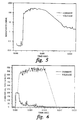
- Figure 2 shows a voltage pulse utilized to simulate a short-circuit condition. For about the first millisecond, the voltage is about 2.5V simulating normal circuit operation. The voltage then jumps to about 100V for about 3 milliseconds simulating a short-circuit condition. The voltage is then reduced back to about 2.5V in about 4 milliseconds simulating the correction of the short-circuit.
- Figure 3 illustrates the current through the current limiting device and voltage across it when the voltage pulse, shown in Figure 2, is applied to the current limiting device.
- Figure 4 illustrates a close-up of the early portion of the simulated short-circuit. It should be noted that when the voltage climbs to about 100V, the current climbs to about 190A and then suddenly drops to a low value of about 1A, then stays at that low value for the duration of the pulse. Thus, the current has been limited from a prospective value of about 1,667A (100V/0.06 ohm) to a value of less than 1A.
- Figure 5 illustrates the resistance of the current limiting device as a function of time. Note that the resistance switches by a factor of greater than 3,000 when the about 100V pulse hits the sample current limiting device. After the completion of this pulse test, the current limiting device resistance returned to its initial value of about 0.06A (measured using a 30A current probe). The current limiting device was thus ready for further current limiting operations. In fact, the current limiting device was put through three more current-limiting operations without any type of failure and, based upon the low level of damage to both the material and the electrodes, there appears to be no reason to believe that the current limiting device could not have worked many more times.
- FIG. 6-8 Another example of current limiting, according to the present invention, using a preferred electrically conductive composite material are shown in Figures 6-8.
- This example utilizes the current limiter device structure shown in Figure 1 with a composite material comprising a thermoset binder, specifically an epoxy binder (Epoxy-Technology Inc. N30 material) and a metal, specifically nickel powder, as the conducting filler material.
- This material has a resistivity of about 0.02-0.03 ohm-cm and does not exhibit a PTCR effect.
- the devices used in these examples had nickel-electroplated copper electrodes that were about 1/4 inch in diameter and were centered on the material which had a 3/4 inch diameter and a thickness of about 1/8 inch.
- the sample current limiting device acted as a simple resistor with a resistance of about 0.1 ohm when less than 30A of current was applied through the current limiting device.
- Figure 6 illustrates the current through and the voltage across the device when a voltage pulse of approximately 500V intended to simulate short-circuit conditions was applied across the device.
- the current rises to about 200A and then maintains that value for about 1.2 milliseconds.
- This initial current value of about 200A is limited by the output capability of the voltage pulsing apparatus used in this test. Due to this instrumental limitation, the voltage does not reach 500V during this initial 1.2 milliseconds. However, during this initial 1.2 milliseconds the voltage across the device rises as the device transitions into its high resistance state.
- the current has been forced down to values below about 50A by the action of the current limiter as the current limiter reaches its high resistance state and the full 500V is measured across the current limiter device.
- the current remained at a level below about 50A until the voltage across the device was terminated at 14 milliseconds.
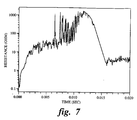
- Figure 7 illustrates the resistance of the current limiter device obtained from the data obtained from Figure 6 by dividing the voltage waveform by the current waveform. Note that at the beginning of the voltage pulse the resistance was about 0.1 ohm and that the resistance rises to values greater than about 10 ohm after about 1.2 milliseconds and maintained this high resistance state until the voltage pulse terminated at 14 milliseconds. After this demonstration of current limiting, it was verified that the current limiting device regained its initial low resistance value of 0.1A under low current ( ⁇ 30A) conditions. This test sequence was repeated successfully with the same device for a total of three operations with 500V short-circuit simulation voltage pulses in order to prove that this current limiting device could perform as a reusable current limiter.
- Figure 8 illustrates that the current limiting device of the present invention can also be used as a reusable current-limiter for alternating current (AC) circuits.
- the current limiting device used in the experiment illustrated by Figure 8 was identical in material and construction to the device used in the previous example for direct current (DC) circuits.
- Figure 8 illustrates the current and voltage waveform when about a 60Hz AC voltage pulse with about 370V amplitude and about 150 milliseconds time duration was applied to the current limiting device.
- the AC pulse was applied with a closing phase angle of approximately 120 degrees for approximately 40 milliseconds. Note that the current increased to a value of approximately +100A, then decreased and crossed 0A as the voltage crossed 0V and then increased in magnitude to a value of approximately -100A.
- the current magnitude was then forced down to a level of less than about 2A by the action of the current limiting device even as the voltage magnitude continued to rise.
- the current magnitude then remained at a level of less than about 2A as the AC voltage continued to oscillate between +370 and -370V for approximately 195 milliseconds when the AC voltage pulse was terminated.
- the current limiting device attained a high resistance state with a greater than 185 ohm resistance value.
- the current limiting device of the present invention works more than once (as opposed to a fuse); is triggered by heating at the interface due to contact resistance; requires a low pyrolysis/decomposition/ablation temperature binder ( ⁇ 800°C) such as organic binder with electrically conducting filler; is combined with metal and/or semiconductor electrodes under pressure; does not require that the material exhibit PTCR effect; limits AC and DC voltage/current waveforms; has been tested to voltages up to 500V (presently unclear what upper limit may be); and has electrodes which can be integrally attached or simply pressure contacted to the material.
- a low pyrolysis/decomposition/ablation temperature binder ⁇ 800°C
- organic binder with electrically conducting filler is combined with metal and/or semiconductor electrodes under pressure
- limits AC and DC voltage/current waveforms has been tested to voltages up to 500V (presently unclear what upper limit may be); and has electrodes which can be integrally attached or simply pressure contacted to the material.
- thermoset binder specifically, an epoxy binder with a metal filler, specifically silver, as the conducting filler was prepared using the following silver particles from Ames Goldsmith Corp. Ag 4300 (5.6g), Ag 1036 (4.2g), Ag 1024 (4.2g) and a two component commercial epoxy (Epotek 301) obtained from Epoxy Technology Inc.
- the epoxy resin (2.3g) was mixed with the hardener (0.6g) and then the silver particles were added and the mixture was placed in a Teflon® mold and cured at 60C for 1 hour.
- the electrodes were made of Ni-coated Cu.
- thermoset binder specifically an epoxy binder with a metal, specifically Silver, as the conducting filler was prepared using Ablebon® 967-1 (Commercial Conducting Adhesive Material from Ablestik Electronic Materials & Adhesives (a subsidiary of National Starch and Chemical Company) was placed in a Teflon® mold and cured at 80C for about 2 hours.
- the electrodes were made of Ni-coated Cu.
- thermoset binder specifically an epoxy binder with a metal, specifically Nickel, as the conducting filler was prepared using Epotek N30 (Commercial Conducting Adhesive Material from Epoxy Technology Inc.) was placed in a Teflon® mold and cured at 150C for about 1 hour. With this specific electrically conductive composite material, separate current limiting devices having the electrodes made of Ni-coated Cu, Stainless Steel, Ag-coated Cu and Cu were tested.
- An elastomer binder specifically a Silicone binder with a two component metal conducting filler, specifically Silver + Aluminum, as the conducting filler was prepared by mixing two parts, A & B.
- the A part comprised a vinyl silicone organopolysiloxane fluid having terminal dimethylvinylsiloxy units and dimethylsiloxy units (400 cps, 23g), 37.3g of aluminum powder, the following silver particles from Ames Goldsmith Corp. Ag 4300 (46.6g), Ag 1036 (37.3g) and Ag 1024 (37.3g), and a silicone hydride siloxane fluid having terminal trimethyl siloxy units to provide a fluid with about 0.8% by weight chemically combined hydrogen attached to silicon (1g).
- the B part comprised vinyl silicone organopolysiloxane fluid having terminal dimethylvinylsiloxy units and dimethylsiloxy units with a viscosity of 400 cps (2g), dimethyl maleate (14 ⁇ L) and Karstedt's platinum catalyst, mentioned above (83 ⁇ L of a 5% platinum solution in xylene).
- the A component (40g) and B component (0.44g) were mixed and then poured into a mold and then cured in a Carver press at about 150°C for about 30 minutes at about 5000 pounds pressure.
- the electrodes were made of either Ni-coated Cu or an n-type Si (semiconductor).
- An elastomer binder, specifically a Silicone binder, with a metal conducting filler, specifically Silver only, as the conducting filler was prepared by mixing two parts, A & B.
- the A part comprised a vinyl silicone organopolysiloxane fluid having terminal dimethylvinylsiloxy units and dimethylsiloxy units (400 cps, 23g), the following silver particles from Ames Goldsmith Corp. Ag 4300 (46.6g), Ag 1036 (37.3g) and Ag 1024 (37.3g), and a silicone hydride siloxane fluid having terminal trimethyl siloxy units to provide a fluid with about 0.8% by weight chemically combined hydrogen attached to silicon (1g).
- the B part was comprised the vinyl silicone organopolysiloxane fluid having terminal dimethylvinylsiloxy units and dimethylsiloxy units with a viscosity of 400 cps (2g), dimethyl maleate (14 ⁇ L) and Karstedt's platinum catalyst, as mentioned above (83 ⁇ L of a 5% platinum solution in xylene).
- the A component (40g) and B component (0.44g) were mixed and then poured into a mold and then cured in a Carver press at 150°C, 30 minutes at 5000 pounds pressure.
- the electrodes were made of Ni-coated Cu.
- An elastomer binder specifically a silver-filled, curable silicone was made from two parts, A & B.
- the A part comprised a vinyl silicone organopolysiloxane fluid having terminal dimethylvinylsiloxy units and dimethylsiloxy units (400 cps, 33g), the following silver particles from Ames Goldsmith Corp. Ag 4300 (46.6g), Ag 1036 (37.3g) and Ag 1024 (37.3g), alpha quartz (Minusil, 23g) and a silicone hydride siloxane fluid having terminal trimethyl siloxy units to provide a fluid with about 0.8% by weight chemically combined hydrogen attached to silicon (2g).
- the B part comprised the vinyl silicone organopolysiloxane fluid having terminal dimethylvinylsiloxy units and dimethylsiloxy units with a viscosity of 400 cps (10g), dimethyl maleate (70 ⁇ L) and Karstedt's platinum catalyst, as mentioned above (415 ⁇ L of a 5% platinum solution in xylene).
- the A component (40g) and B component (0.5g) were mixed and then poured into a mold and then cured in a Carver press at about 150°C for about 30 minutes at about 5000 pounds pressure.
- the electrodes were made of Ni-coated Cu.
- a reinforced elastomer binder specifically a curable silicone reinforced with fumed silica, with a two component metal filler, specifically, silver and aluminum was made with an A part and a B part.
- the A part was composed of an elastomer binder, specifically a vinyl silicone organopolysiloxane fluid having terminal dimethylvinylsiloxy units and dimethylsiloxy units (400 cps, 23g), a silicone hydride siloxane fluid having terminal trimethyl siloxy units to provide a fluid with about 0.8% by weight chemically combined hydrogen attached to silicon (2g), doubly treated fumed silica (300 m 2 /g, treated with cyclooctamethyltetrasiloxane and with hexamethyldisilazane, 1.2g),aluminum powder (37.3g), silver particles from Ames Goldsmith Corp.
- the B part was composed of the vinyl silicone organopolysiloxane fluid having terminal dimethylvinylsiloxy units and dimethylsiloxy units (400 cps, 2g), dimethylmaleate (14 ⁇ L) and Karstedt's platinum catalyst (83 ⁇ L).
- a curable formulation was prepared by combining the A part (40g) and the B part (0.44g) and then hand mixing and placing in a mold. Cure was accomplished in a Carver press at 5000 pounds pressure and 150°C for 30 min.
- the electrodes were made of Ni-coated Cu.
- An elastomer binder specifically a nickel filled silicone, was made from two parts, A & B.
- the A part consisted of a vinyl silicone organopolysiloxane fluid having terminal dimethylvinylsiloxy units and dimethylsiloxy units (400 cps, 25g), nickel powder (INCO type 123, 100g) and a silicone hydride siloxane fluid having terminal trimethyl siloxy units to provide a fluid with about 0.8% by weight chemically combined hydrogen attached to silicon (2g).
- the B part was composed of the vinyl silicone organopolysiloxane fluid having terminal dimethylvinylsiloxy units and dimethylsiloxy units with a viscosity of 400 cps (10g), dimethyl maleate (70 ⁇ L) and Karstedt's platinum catalyst (415 ⁇ L of a 5% platinum solution in xylene).
- the A component (40g) and B component (0.5g) were mixed and then poured into a mold and then cured in a Carver press at 150°C, 30 minutes at 5000 pounds pressure.
- the electrodes were made of Ni-coated Cu.
- thermoplastic binder specifically polytetrafluoroethylene binder, with a semiconductor conducting filler, specifically Carbon Black was commercially obtained.
- GS-2100-080-5000-SC Common Conductive Fluoropolymer from W. L. Gore & Associates, Inc.
- electrodes made of Ni-coated Cu were utilized.
- thermoplastic binder specifically Poly(ethylene glycol) with a metal filler, specifically Silver, as the conducting filler was made.
- a silver particle mixture comprising the following particles from Ames Goldsmith Corp., Ag 4300 (2.8g), Ag 1036 (2.1g), Ag 1024 (2.1g) was heated to about 80C and then poured into molten Poly(ethyleneglycol) (MW8000) at about 80°C and mixed. The material was then poured into a Teflon® mold and allowed to harden at room temperature.
- the electrodes were made of Ni-coated Cu.
- the electrodes when tested as a current limiter, were pressed against the electrically conductive composite material at pressures ranging from about six (6) to about three hundred seventy (370) PSI. Specifically, the pressure used in examples 3, 4, 6, 7 and 11 was about 170 PSI; examples 5, 8 and 10 was about 370 PSI; and examples 9 and 12 was about 6 PSI. While the above pressure range was actually tested, it may be possible that the device of the present invention will perform properly at higher or lower pressures.
- a binder material having a low pyrolysis or vaporization temperature such as: a thermoplastic (for example, polytetrafluoroethylene, poly(ethyleneglycol), polyethylene, polycarbonate, polyimide, polyamide, polymethylmethacrylate, polyester etc.); a thermoset plastic (for example, epoxy, polyester, polyurethane, phenolic, alkyd); an elastomer (for example, silicone (polyorganosiloxane), (poly)urethane, isoprene rubber, neoprene, etc.); an organic or inorganic crystal; combined with an electrically conducting filler such as a metal (for example, nickel, silver, copper, etc.) or a semiconductor (for example, carbon black, titanium dioxide, etc.) with a particulate or foam structure; combined with a metal or semiconductor electrode pressure contacted to the electrically conducting composite material, could also perform effectively in the current limiter of the present invention.
- a thermoplastic for example, polytetrafluoro
- Third phase fillers could be used to improve specific properties of the composite such as the mechanical properties; dielectric properties; or to provide arc-quenching properties or flame-retardant properties.
- Materials which could be used as a third phase filler in the composite material include: a filler selected from reinforcing fillers such as fumed silica, or extending fillers such as precipitated silica and mixtures thereof.
- fillers include titanium dioxide, lithopone, zinc oxide, diatomaceous silicate, silica aerogel, iron oxide, diatomaceous earth, calcium carbonate, silazane treated silicas, silicone treated silicas, glass fibers, magnesium oxide, chromic oxide, zirconium oxide, alpha-quartz, calcined clay, carbon, graphite, cork, cotton sodium bicarbonate, boric acid, alumina-hydrate, etc..
- additives may include: impact modifiers for preventing damage to the current limiter such as cracking upon sudden impact; flame retardant for preventing flame formation and/or inhibiting flame formation in the current limiter; dyes and colorants for providing specific color components in response to customer requirements; UV screens for preventing reduction in component physical properties due to exposure to sunlight or other forms of UV radiation.
- the current limiter of the present invention could be utilized with parallel linear or nonlinear circuit element(s) such as resistor(s) or varistor(s).
Applications Claiming Priority (2)
| Application Number | Priority Date | Filing Date | Title |
|---|---|---|---|
| US08/514,076 US5614881A (en) | 1995-08-11 | 1995-08-11 | Current limiting device |
| US514076 | 1995-08-11 |
Publications (2)
| Publication Number | Publication Date |
|---|---|
| EP0762439A2 true EP0762439A2 (fr) | 1997-03-12 |
| EP0762439A3 EP0762439A3 (fr) | 1997-10-15 |
Family
ID=24045702
Family Applications (1)
| Application Number | Title | Priority Date | Filing Date |
|---|---|---|---|
| EP96304363A Ceased EP0762439A3 (fr) | 1995-08-11 | 1996-06-11 | Dispositif limiteur de courant |
Country Status (5)
| Country | Link |
|---|---|
| US (2) | US5614881A (fr) |
| EP (1) | EP0762439A3 (fr) |
| JP (1) | JP3896175B2 (fr) |
| CN (1) | CN1076896C (fr) |
| BR (1) | BR9602736A (fr) |
Cited By (7)
| Publication number | Priority date | Publication date | Assignee | Title |
|---|---|---|---|---|
| EP0852385A1 (fr) * | 1997-01-02 | 1998-07-08 | General Electric Company | Dispositif de limitation du courant |
| FR2759490A1 (fr) * | 1997-02-10 | 1998-08-14 | Gen Electric | Ensemble de disjoncteur a element de suppression du courant pour la protection des moteurs a induction |
| EP0896344A2 (fr) * | 1997-07-21 | 1999-02-10 | General Electric Company | Dispositif limitateur de courant en matériau composite électriquement conducteur et procédé de fabrication du matériau électriquement conducteur |
| WO1999036927A1 (fr) * | 1998-01-14 | 1999-07-22 | General Electric Company | Coupe-circuit a fonction d'interruption d'arc amelioree |
| WO2001047078A2 (fr) * | 1999-12-23 | 2001-06-28 | Mcgraw Edison Company | Joint elastique forme entre des composants electriques |
| EP1187278A2 (fr) * | 2000-08-28 | 2002-03-13 | Takashi Katoda | Elément principal d'un dispositif de protection contre les surtensions |
| US8085520B2 (en) | 2004-01-23 | 2011-12-27 | Cooper Technologies Company | Manufacturing process for surge arrester module using pre-impregnated composite |
Families Citing this family (69)
| Publication number | Priority date | Publication date | Assignee | Title |
|---|---|---|---|---|
| US5614881A (en) * | 1995-08-11 | 1997-03-25 | General Electric Company | Current limiting device |
| US6232866B1 (en) * | 1995-09-20 | 2001-05-15 | The United States Of America As Represented By The Administrator Of The National Aeronautics And Space Administration | Composite material switches |
| DE19542162C2 (de) * | 1995-11-11 | 2000-11-23 | Abb Research Ltd | Überstrombegrenzer |
| JP3544092B2 (ja) * | 1997-01-31 | 2004-07-21 | 東レ・ダウコーニング・シリコーン株式会社 | 高電圧電気絶縁部品用液状シリコーンゴム組成物およびその製造方法 |
| US5859578A (en) * | 1997-03-04 | 1999-01-12 | General Electric Company | Current limiting shunt for current limiting circuit breakers |
| US7336468B2 (en) | 1997-04-08 | 2008-02-26 | X2Y Attenuators, Llc | Arrangement for energy conditioning |
| US7321485B2 (en) | 1997-04-08 | 2008-01-22 | X2Y Attenuators, Llc | Arrangement for energy conditioning |
| US7301748B2 (en) | 1997-04-08 | 2007-11-27 | Anthony Anthony A | Universal energy conditioning interposer with circuit architecture |
| US7274549B2 (en) * | 2000-12-15 | 2007-09-25 | X2Y Attenuators, Llc | Energy pathway arrangements for energy conditioning |
| US9054094B2 (en) | 1997-04-08 | 2015-06-09 | X2Y Attenuators, Llc | Energy conditioning circuit arrangement for integrated circuit |
| US5847630A (en) * | 1997-08-01 | 1998-12-08 | General Electric Company | Compact circuit breaker incorporating a polymer current limiter |
| EP0968503A1 (fr) * | 1997-08-28 | 2000-01-05 | General Electric Company | Dispositif limiteur de courant et son procede de fabrication |
| EP0938736B1 (fr) * | 1997-09-18 | 2004-12-15 | General Electric Company | Disjoncteur limiteur de courant comprenant un commutateur de courant |
| US5968419A (en) * | 1997-12-08 | 1999-10-19 | Westinghouse Electric Company Llc | Conductive polymer compositions, electrical devices and methods of making |
| US6290879B1 (en) | 1998-05-20 | 2001-09-18 | General Electric Company | Current limiting device and materials for a current limiting device |
| US6124780A (en) * | 1998-05-20 | 2000-09-26 | General Electric Company | Current limiting device and materials for a current limiting device |
| US6133820A (en) * | 1998-08-12 | 2000-10-17 | General Electric Company | Current limiting device having a web structure |
| US5963121A (en) * | 1998-11-11 | 1999-10-05 | Ferro Corporation | Resettable fuse |
| US6631058B1 (en) * | 1998-12-22 | 2003-10-07 | Rockwell Automation Technologies, Inc. | Method and apparatus for reducing arc retrogression in a circuit interrupter |
| US6674619B2 (en) | 1998-12-22 | 2004-01-06 | Rockwell Automation Technologies, Inc. | Method for interrupting an electrical circuit |
| US6665157B2 (en) | 1998-12-22 | 2003-12-16 | Rockwell Automation Technologies, Inc. | Apparatus for interrupting an electrical circuit |
| US6667863B1 (en) * | 1998-12-22 | 2003-12-23 | Rockwell Automation Technologies, Inc. | Method and apparatus for interrupting current through deionization of arc plasma |
| US6594126B1 (en) * | 1998-12-22 | 2003-07-15 | Rockwell Automation Technologies, Inc. | Method and apparatus for extinguishing an arc through material surface ablation |
| US6661628B2 (en) | 1998-12-22 | 2003-12-09 | Rockwell Automation Technologies, Inc. | Method for interrupting a current-carrying path |
| US6157528A (en) | 1999-01-28 | 2000-12-05 | X2Y Attenuators, L.L.C. | Polymer fuse and filter apparatus |
| US6144540A (en) | 1999-03-09 | 2000-11-07 | General Electric Company | Current suppressing circuit breaker unit for inductive motor protection |
| US6157286A (en) | 1999-04-05 | 2000-12-05 | General Electric Company | High voltage current limiting device |
| US7190251B2 (en) | 1999-05-25 | 2007-03-13 | Varatouch Technology Incorporated | Variable resistance devices and methods |
| US6404323B1 (en) * | 1999-05-25 | 2002-06-11 | Varatouch Technology Incorporated | Variable resistance devices and methods |
| US6459358B1 (en) | 1999-09-27 | 2002-10-01 | Eaton Corporation | Flexible moldable conductive current-limiting materials |
| US6248970B1 (en) | 1999-11-05 | 2001-06-19 | Siemens Energy & Automation, Inc. | ARC chute for a molded case circuit breaker |
| US6323751B1 (en) | 1999-11-19 | 2001-11-27 | General Electric Company | Current limiter device with an electrically conductive composite material and method of manufacturing |
| US6300586B1 (en) * | 1999-12-09 | 2001-10-09 | General Electric Company | Arc runner retaining feature |
| US6281461B1 (en) | 1999-12-27 | 2001-08-28 | General Electric Company | Circuit breaker rotor assembly having arc prevention structure |
| US6388553B1 (en) | 2000-03-02 | 2002-05-14 | Eaton Corproation | Conductive polymer current-limiting fuse |
| US6359544B1 (en) * | 2000-10-10 | 2002-03-19 | Therm-O-Disc Incorporated | Conductive polymer compositions containing surface treated kaolin clay and devices |
| CA2425946A1 (fr) * | 2000-10-17 | 2002-04-25 | X2Y Attenuators, Llc | Amalgame de protection et chemins d'energie proteges et autres elements pour circuit(s) ou unique ou multiples dote(s) d'un noeud de reference commun |
| US7193831B2 (en) * | 2000-10-17 | 2007-03-20 | X2Y Attenuators, Llc | Energy pathway arrangement |
| US6411191B1 (en) | 2000-10-24 | 2002-06-25 | Eaton Corporation | Current-limiting device employing a non-uniform pressure distribution between one or more electrodes and a current-limiting material |
| DE60134493D1 (de) * | 2000-12-12 | 2008-07-31 | Japan Science & Tech Agency | Lenkmechanismus für elektrisches fahrzeug |
| US6597551B2 (en) * | 2000-12-13 | 2003-07-22 | Huladyne Corporation | Polymer current limiting device and method of manufacture |
| US6798331B2 (en) * | 2001-02-08 | 2004-09-28 | Qortek, Inc. | Current control device |
| US7425885B2 (en) * | 2001-02-15 | 2008-09-16 | Integral Technologies, Inc. | Low cost electrical fuses manufactured from conductive loaded resin-based materials |
| US7180718B2 (en) * | 2003-01-31 | 2007-02-20 | X2Y Attenuators, Llc | Shielded energy conditioner |
| US7474772B2 (en) * | 2003-06-25 | 2009-01-06 | Atrua Technologies, Inc. | System and method for a miniature user input device |
| US7587072B2 (en) | 2003-08-22 | 2009-09-08 | Authentec, Inc. | System for and method of generating rotational inputs |
| KR20060120683A (ko) | 2003-12-22 | 2006-11-27 | 엑스2와이 어테뉴에이터스, 엘.엘.씨 | 내부적으로 차폐된 에너지 컨디셔너 |
| US20050179657A1 (en) * | 2004-02-12 | 2005-08-18 | Atrua Technologies, Inc. | System and method of emulating mouse operations using finger image sensors |
| DE502004007984D1 (de) | 2004-07-08 | 2008-10-16 | Abb Schweiz Ag | Lichtbogenlöscheinrichtung für Schutzschalter |
| US7630188B2 (en) | 2005-03-01 | 2009-12-08 | X2Y Attenuators, Llc | Conditioner with coplanar conductors |
| US7817397B2 (en) | 2005-03-01 | 2010-10-19 | X2Y Attenuators, Llc | Energy conditioner with tied through electrodes |
| US20070061126A1 (en) * | 2005-09-01 | 2007-03-15 | Anthony Russo | System for and method of emulating electronic input devices |
| US7684953B2 (en) * | 2006-02-10 | 2010-03-23 | Authentec, Inc. | Systems using variable resistance zones and stops for generating inputs to an electronic device |
| CN101395683A (zh) | 2006-03-07 | 2009-03-25 | X2Y衰减器有限公司 | 能量调节装置结构 |
| US9235274B1 (en) | 2006-07-25 | 2016-01-12 | Apple Inc. | Low-profile or ultra-thin navigation pointing or haptic feedback device |
| JP5287154B2 (ja) * | 2007-11-08 | 2013-09-11 | パナソニック株式会社 | 回路保護素子およびその製造方法 |
| US8247726B2 (en) * | 2009-07-22 | 2012-08-21 | Eaton Corporation | Electrical switching apparatus and arc chute assembly therefor |
| US8421890B2 (en) | 2010-01-15 | 2013-04-16 | Picofield Technologies, Inc. | Electronic imager using an impedance sensor grid array and method of making |
| US8791792B2 (en) | 2010-01-15 | 2014-07-29 | Idex Asa | Electronic imager using an impedance sensor grid array mounted on or about a switch and method of making |
| US8866347B2 (en) | 2010-01-15 | 2014-10-21 | Idex Asa | Biometric image sensing |
| US20130279769A1 (en) | 2012-04-10 | 2013-10-24 | Picofield Technologies Inc. | Biometric Sensing |
| KR102117186B1 (ko) | 2012-04-20 | 2020-06-02 | 비쉐이-실리코닉스 | 전류 제한 시스템 및 방법 |
| US8836404B2 (en) | 2012-08-02 | 2014-09-16 | Vishay-Siliconix | Circuit for preventing reverse conduction |
| US9029727B2 (en) * | 2013-01-24 | 2015-05-12 | Eaton Corporation | Arc runners suitable for DC molded case circuit breakers and related methods |
| FR3048555B1 (fr) * | 2016-03-02 | 2018-03-16 | Commissariat A L'energie Atomique Et Aux Energies Alternatives | Structure de commutateur comportant plusieurs canaux de materiau a changement de phase et electrodes de commande interdigitees |
| CN106099482B (zh) * | 2016-08-26 | 2019-01-18 | 徐州巨业机械制造有限公司 | 抗杂音耳机孔 |
| CN107946109B (zh) * | 2017-12-23 | 2021-01-12 | 珠海德利和电气有限公司 | 一种避雷器拉弧保护装置 |
| US10483068B1 (en) | 2018-12-11 | 2019-11-19 | Eaton Intelligent Power Limited | Switch disconnector systems suitable for molded case circuit breakers and related methods |
| CN110033910B (zh) * | 2019-05-10 | 2024-03-26 | 成都铁达电子股份有限公司 | 一种可实现定向炸裂的压敏电阻 |
Citations (5)
| Publication number | Priority date | Publication date | Assignee | Title |
|---|---|---|---|---|
| US3648002A (en) * | 1970-05-04 | 1972-03-07 | Essex International Inc | Current control apparatus and methods of manufacture |
| US4107640A (en) * | 1975-11-19 | 1978-08-15 | Kabushiki Kaisha Tokai Rika Denki Seisakusho | Current limiting element for preventing electrical overcurrent |
| US4292261A (en) * | 1976-06-30 | 1981-09-29 | Japan Synthetic Rubber Company Limited | Pressure sensitive conductor and method of manufacturing the same |
| EP0640995A1 (fr) * | 1993-08-25 | 1995-03-01 | Abb Research Ltd. | Résistance électrique et application de cette résistance dans un limiteur de courant |
| DE4330607A1 (de) * | 1993-09-09 | 1995-03-16 | Siemens Ag | Limiter zur Strombegrenzung |
Family Cites Families (37)
| Publication number | Priority date | Publication date | Assignee | Title |
|---|---|---|---|---|
| US2933574A (en) * | 1954-04-26 | 1960-04-19 | Westinghouse Electric Corp | Circuit interrupters |
| DE1149648B (de) * | 1961-06-16 | 1963-05-30 | Bosch Gmbh Robert | Impulsgeber fuer elektrische Signalanlagen, wie Blinklichtanlagen, insbesondere zur Fahrtrichtungsanzeige von Kraftfahrzeugen |
| US3243753A (en) * | 1962-11-13 | 1966-03-29 | Kohler Fred | Resistance element |
| US3673121A (en) * | 1970-01-27 | 1972-06-27 | Texas Instruments Inc | Process for making conductive polymers and resulting compositions |
| US4017715A (en) * | 1975-08-04 | 1977-04-12 | Raychem Corporation | Temperature overshoot heater |
| US4101862A (en) * | 1976-11-19 | 1978-07-18 | K.K. Tokai Rika Denki Seisakusho | Current limiting element for preventing electrical overcurrent |
| US4304987A (en) * | 1978-09-18 | 1981-12-08 | Raychem Corporation | Electrical devices comprising conductive polymer compositions |
| US4317027A (en) * | 1980-04-21 | 1982-02-23 | Raychem Corporation | Circuit protection devices |
| US4511772A (en) * | 1983-05-11 | 1985-04-16 | Eaton Corporation | Arc extinguishing structure for electrical switching device |
| EP0225207B1 (fr) * | 1985-10-31 | 1991-05-15 | Merlin Gerin | Chaîne cinématique de transmission entre le mécanisme de commande et les pôles d'un disjoncteur électrique à boîtier isolant moulé |
| US4649455A (en) * | 1986-04-28 | 1987-03-10 | General Electric Company | Rating plug for molded case circuit breaker |
| US4652975A (en) * | 1986-04-28 | 1987-03-24 | General Electric Company | Mounting arrangement for circuit breaker current sensing transformers |
| US4746896A (en) * | 1986-05-08 | 1988-05-24 | North American Philips Corp. | Layered film resistor with high resistance and high stability |
| US4754247A (en) * | 1987-06-12 | 1988-06-28 | General Electric Company | Molded case circuit breaker accessory enclosure |
| US4789848A (en) * | 1987-09-03 | 1988-12-06 | General Electric Company | Molded case circuit breaker latch and operating mechanism assembly |
| US5166658A (en) * | 1987-09-30 | 1992-11-24 | Raychem Corporation | Electrical device comprising conductive polymers |
| US5068634A (en) * | 1988-01-11 | 1991-11-26 | Electromer Corporation | Overvoltage protection device and material |
| NO880529L (no) * | 1988-02-08 | 1989-08-09 | Ramu Int | Selvbegrensede elektrisk varmeelement. |
| JPH01225031A (ja) * | 1988-03-02 | 1989-09-07 | Yaskawa Electric Mfg Co Ltd | 事故電流限流装置 |
| US4806893A (en) * | 1988-03-03 | 1989-02-21 | General Electric Company | Molded case circuit breaker actuator-accessory unit |
| US4963849A (en) * | 1989-04-28 | 1990-10-16 | General Electric Company | Compact current limiting circuit breaker |
| US4970481A (en) * | 1989-11-13 | 1990-11-13 | General Electric Company | Current limiting circuit breaker contact arm configuration |
| SE465524B (sv) * | 1990-02-08 | 1991-09-23 | Asea Brown Boveri | Anordning foer oeverlast- och kortslutningsskydd i elektriska anlaeggningar |
| JPH047801A (ja) * | 1990-04-25 | 1992-01-13 | Daito Tsushinki Kk | Ptc素子 |
| SE468026B (sv) * | 1990-06-05 | 1992-10-19 | Asea Brown Boveri | Saett att framstaella en elektrisk anordning |
| US5260848A (en) * | 1990-07-27 | 1993-11-09 | Electromer Corporation | Foldback switching material and devices |
| US5382938A (en) * | 1990-10-30 | 1995-01-17 | Asea Brown Boveri Ab | PTC element |
| JPH05295269A (ja) * | 1991-11-29 | 1993-11-09 | General Electric Co <Ge> | 熱硬化性オルガノポリシロキサン組成物、予備生成済み潜伏性白金触媒およびそれの調製方法 |
| DE4142523A1 (de) * | 1991-12-21 | 1993-06-24 | Asea Brown Boveri | Widerstand mit ptc - verhalten |
| DE4221309A1 (de) * | 1992-06-29 | 1994-01-05 | Abb Research Ltd | Strombegrenzendes Element |
| FR2696273B1 (fr) * | 1992-09-25 | 1994-11-18 | Telemecanique | Disjoncteur électrique à soufflage magnétique. |
| DE4232969A1 (de) * | 1992-10-01 | 1994-04-07 | Abb Research Ltd | Elektrisches Widerstandselement |
| US5451919A (en) * | 1993-06-29 | 1995-09-19 | Raychem Corporation | Electrical device comprising a conductive polymer composition |
| FR2714520B1 (fr) * | 1993-12-24 | 1996-01-19 | Telemecanique | Appareil électrique interrupteur à contacts séparables. |
| US5436274A (en) * | 1994-09-30 | 1995-07-25 | General Electric Company | Preparation of silicone foams of low density and small cell size |
| US5539370A (en) * | 1995-02-17 | 1996-07-23 | General Electric Company | Inductive motor protective circuit breaker |
| US5614881A (en) * | 1995-08-11 | 1997-03-25 | General Electric Company | Current limiting device |
-
1995
- 1995-08-11 US US08/514,076 patent/US5614881A/en not_active Expired - Fee Related
-
1996
- 1996-06-10 JP JP14634496A patent/JP3896175B2/ja not_active Expired - Fee Related
- 1996-06-11 EP EP96304363A patent/EP0762439A3/fr not_active Ceased
- 1996-06-11 CN CN96110099A patent/CN1076896C/zh not_active Expired - Fee Related
- 1996-06-11 BR BR9602736A patent/BR9602736A/pt not_active IP Right Cessation
-
1997
- 1997-02-10 US US08/797,152 patent/US5877467A/en not_active Expired - Fee Related
Patent Citations (5)
| Publication number | Priority date | Publication date | Assignee | Title |
|---|---|---|---|---|
| US3648002A (en) * | 1970-05-04 | 1972-03-07 | Essex International Inc | Current control apparatus and methods of manufacture |
| US4107640A (en) * | 1975-11-19 | 1978-08-15 | Kabushiki Kaisha Tokai Rika Denki Seisakusho | Current limiting element for preventing electrical overcurrent |
| US4292261A (en) * | 1976-06-30 | 1981-09-29 | Japan Synthetic Rubber Company Limited | Pressure sensitive conductor and method of manufacturing the same |
| EP0640995A1 (fr) * | 1993-08-25 | 1995-03-01 | Abb Research Ltd. | Résistance électrique et application de cette résistance dans un limiteur de courant |
| DE4330607A1 (de) * | 1993-09-09 | 1995-03-16 | Siemens Ag | Limiter zur Strombegrenzung |
Cited By (12)
| Publication number | Priority date | Publication date | Assignee | Title |
|---|---|---|---|---|
| EP0852385A1 (fr) * | 1997-01-02 | 1998-07-08 | General Electric Company | Dispositif de limitation du courant |
| FR2759490A1 (fr) * | 1997-02-10 | 1998-08-14 | Gen Electric | Ensemble de disjoncteur a element de suppression du courant pour la protection des moteurs a induction |
| EP0896344A2 (fr) * | 1997-07-21 | 1999-02-10 | General Electric Company | Dispositif limitateur de courant en matériau composite électriquement conducteur et procédé de fabrication du matériau électriquement conducteur |
| EP0896344A3 (fr) * | 1997-07-21 | 1999-07-07 | General Electric Company | Dispositif limitateur de courant en matériau composite électriquement conducteur et procédé de fabrication du matériau électriquement conducteur |
| US6191681B1 (en) | 1997-07-21 | 2001-02-20 | General Electric Company | Current limiting device with electrically conductive composite and method of manufacturing the electrically conductive composite |
| WO1999036927A1 (fr) * | 1998-01-14 | 1999-07-22 | General Electric Company | Coupe-circuit a fonction d'interruption d'arc amelioree |
| WO2001047078A2 (fr) * | 1999-12-23 | 2001-06-28 | Mcgraw Edison Company | Joint elastique forme entre des composants electriques |
| WO2001047078A3 (fr) * | 1999-12-23 | 2002-01-03 | Mc Graw Edison Co | Joint elastique forme entre des composants electriques |
| US6483685B1 (en) | 1999-12-23 | 2002-11-19 | Mcgraw Edison Company | Compliant joint between electrical components |
| EP1187278A2 (fr) * | 2000-08-28 | 2002-03-13 | Takashi Katoda | Elément principal d'un dispositif de protection contre les surtensions |
| EP1187278A3 (fr) * | 2000-08-28 | 2005-07-06 | Takashi Katoda | Elément principal d'un dispositif de protection contre les surtensions |
| US8085520B2 (en) | 2004-01-23 | 2011-12-27 | Cooper Technologies Company | Manufacturing process for surge arrester module using pre-impregnated composite |
Also Published As
| Publication number | Publication date |
|---|---|
| JPH09168233A (ja) | 1997-06-24 |
| US5877467A (en) | 1999-03-02 |
| CN1076896C (zh) | 2001-12-26 |
| JP3896175B2 (ja) | 2007-03-22 |
| CN1146088A (zh) | 1997-03-26 |
| US5614881A (en) | 1997-03-25 |
| EP0762439A3 (fr) | 1997-10-15 |
| BR9602736A (pt) | 1998-09-08 |
Similar Documents
| Publication | Publication Date | Title |
|---|---|---|
| US5614881A (en) | Current limiting device | |
| US6128168A (en) | Circuit breaker with improved arc interruption function | |
| CA1262470A (fr) | Methode de regulation d'un appareil de chauffage | |
| US4967176A (en) | Assemblies of PTC circuit protection devices | |
| US4475138A (en) | Circuit protection devices comprising PTC element | |
| US5691689A (en) | Electrical circuit protection devices comprising PTC conductive liquid crystal polymer compositions | |
| CN1262057C (zh) | 电子开关 | |
| US4785163A (en) | Method for monitoring a heater | |
| EP1233427B1 (fr) | Dispositifs de protection monocouches et multicouches à tension variable | |
| US6711807B2 (en) | Method of manufacturing composite array structure | |
| US5565826A (en) | Overload protective system | |
| US6133820A (en) | Current limiting device having a web structure | |
| US5545679A (en) | Positive temperature coefficient conductive polymer made from thermosetting polyester resin and conductive fillers | |
| EP0725993B1 (fr) | Systeme de protection contre les surcharges | |
| US20020011591A1 (en) | Current limiting device and materials for a current limiting device | |
| US5929744A (en) | Current limiting device with at least one flexible electrode | |
| US6411191B1 (en) | Current-limiting device employing a non-uniform pressure distribution between one or more electrodes and a current-limiting material | |
| EP0852385A1 (fr) | Dispositif de limitation du courant | |
| US6535103B1 (en) | Current limiting arrangement and method | |
| WO1999010898A1 (fr) | Dispositif limiteur de courant et son procede de fabrication | |
| US5977861A (en) | Current limiting device with grooved electrode structure | |
| PT102038B (pt) | Dispositivo limitador de corrente | |
| Sun et al. | The voltage dependence of switching in a polymer current limiter device | |
| Duggal | An upper limit for high power switching with a polymer current limiter device | |
| Fang et al. | Limit current surges with+ TC resistors |
Legal Events
| Date | Code | Title | Description |
|---|---|---|---|
| PUAI | Public reference made under article 153(3) epc to a published international application that has entered the european phase |
Free format text: ORIGINAL CODE: 0009012 |
|
| AK | Designated contracting states |
Kind code of ref document: A2 Designated state(s): DE ES FR IT |
|
| PUAL | Search report despatched |
Free format text: ORIGINAL CODE: 0009013 |
|
| AK | Designated contracting states |
Kind code of ref document: A3 Designated state(s): DE ES FR IT |
|
| PUAL | Search report despatched |
Free format text: ORIGINAL CODE: 0009013 |
|
| 17P | Request for examination filed |
Effective date: 19980714 |
|
| 17Q | First examination report despatched |
Effective date: 20020829 |
|
| STAA | Information on the status of an ep patent application or granted ep patent |
Free format text: STATUS: THE APPLICATION HAS BEEN REFUSED |
|
| 18R | Application refused |
Effective date: 20080425 |