EP0763369B1 - Needle shield with collapsible cover - Google Patents
Needle shield with collapsible cover Download PDFInfo
- Publication number
- EP0763369B1 EP0763369B1 EP96306465A EP96306465A EP0763369B1 EP 0763369 B1 EP0763369 B1 EP 0763369B1 EP 96306465 A EP96306465 A EP 96306465A EP 96306465 A EP96306465 A EP 96306465A EP 0763369 B1 EP0763369 B1 EP 0763369B1
- Authority
- EP
- European Patent Office
- Prior art keywords
- needle
- handle
- distal
- proximal portion
- proximal
- Prior art date
- Legal status (The legal status is an assumption and is not a legal conclusion. Google has not performed a legal analysis and makes no representation as to the accuracy of the status listed.)
- Expired - Lifetime
Links
Images


Classifications
-
- A—HUMAN NECESSITIES
- A61—MEDICAL OR VETERINARY SCIENCE; HYGIENE
- A61M—DEVICES FOR INTRODUCING MEDIA INTO, OR ONTO, THE BODY; DEVICES FOR TRANSDUCING BODY MEDIA OR FOR TAKING MEDIA FROM THE BODY; DEVICES FOR PRODUCING OR ENDING SLEEP OR STUPOR
- A61M25/00—Catheters; Hollow probes
- A61M25/01—Introducing, guiding, advancing, emplacing or holding catheters
- A61M25/06—Body-piercing guide needles or the like
- A61M25/0612—Devices for protecting the needle; Devices to help insertion of the needle, e.g. wings or holders
- A61M25/0631—Devices for protecting the needle; Devices to help insertion of the needle, e.g. wings or holders having means for fully covering the needle after its withdrawal, e.g. needle being withdrawn inside the handle or a cover being advanced over the needle
-
- A—HUMAN NECESSITIES
- A61—MEDICAL OR VETERINARY SCIENCE; HYGIENE
- A61M—DEVICES FOR INTRODUCING MEDIA INTO, OR ONTO, THE BODY; DEVICES FOR TRANSDUCING BODY MEDIA OR FOR TAKING MEDIA FROM THE BODY; DEVICES FOR PRODUCING OR ENDING SLEEP OR STUPOR
- A61M5/00—Devices for bringing media into the body in a subcutaneous, intra-vascular or intramuscular way; Accessories therefor, e.g. filling or cleaning devices, arm-rests
- A61M5/178—Syringes
- A61M5/31—Details
- A61M5/32—Needles; Details of needles pertaining to their connection with syringe or hub; Accessories for bringing the needle into, or holding the needle on, the body; Devices for protection of needles
- A61M5/3205—Apparatus for removing or disposing of used needles or syringes, e.g. containers; Means for protection against accidental injuries from used needles
- A61M5/321—Means for protection against accidental injuries by used needles
- A61M5/3243—Means for protection against accidental injuries by used needles being axially-extensible, e.g. protective sleeves coaxially slidable on the syringe barrel
-
- A—HUMAN NECESSITIES
- A61—MEDICAL OR VETERINARY SCIENCE; HYGIENE
- A61M—DEVICES FOR INTRODUCING MEDIA INTO, OR ONTO, THE BODY; DEVICES FOR TRANSDUCING BODY MEDIA OR FOR TAKING MEDIA FROM THE BODY; DEVICES FOR PRODUCING OR ENDING SLEEP OR STUPOR
- A61M5/00—Devices for bringing media into the body in a subcutaneous, intra-vascular or intramuscular way; Accessories therefor, e.g. filling or cleaning devices, arm-rests
- A61M5/178—Syringes
- A61M5/31—Details
- A61M5/32—Needles; Details of needles pertaining to their connection with syringe or hub; Accessories for bringing the needle into, or holding the needle on, the body; Devices for protection of needles
- A61M5/3205—Apparatus for removing or disposing of used needles or syringes, e.g. containers; Means for protection against accidental injuries from used needles
- A61M5/321—Means for protection against accidental injuries by used needles
- A61M5/322—Retractable needles, i.e. disconnected from and withdrawn into the syringe barrel by the piston
- A61M5/3232—Semi-automatic needle retraction, i.e. in which triggering of the needle retraction requires a deliberate action by the user, e.g. manual release of spring-biased retraction means
-
- A—HUMAN NECESSITIES
- A61—MEDICAL OR VETERINARY SCIENCE; HYGIENE
- A61M—DEVICES FOR INTRODUCING MEDIA INTO, OR ONTO, THE BODY; DEVICES FOR TRANSDUCING BODY MEDIA OR FOR TAKING MEDIA FROM THE BODY; DEVICES FOR PRODUCING OR ENDING SLEEP OR STUPOR
- A61M5/00—Devices for bringing media into the body in a subcutaneous, intra-vascular or intramuscular way; Accessories therefor, e.g. filling or cleaning devices, arm-rests
- A61M5/178—Syringes
- A61M5/31—Details
- A61M5/32—Needles; Details of needles pertaining to their connection with syringe or hub; Accessories for bringing the needle into, or holding the needle on, the body; Devices for protection of needles
- A61M5/3205—Apparatus for removing or disposing of used needles or syringes, e.g. containers; Means for protection against accidental injuries from used needles
- A61M5/321—Means for protection against accidental injuries by used needles
- A61M5/3243—Means for protection against accidental injuries by used needles being axially-extensible, e.g. protective sleeves coaxially slidable on the syringe barrel
- A61M5/3257—Semi-automatic sleeve extension, i.e. in which triggering of the sleeve extension requires a deliberate action by the user, e.g. manual release of spring-biased extension means
-
- A—HUMAN NECESSITIES
- A61—MEDICAL OR VETERINARY SCIENCE; HYGIENE
- A61M—DEVICES FOR INTRODUCING MEDIA INTO, OR ONTO, THE BODY; DEVICES FOR TRANSDUCING BODY MEDIA OR FOR TAKING MEDIA FROM THE BODY; DEVICES FOR PRODUCING OR ENDING SLEEP OR STUPOR
- A61M5/00—Devices for bringing media into the body in a subcutaneous, intra-vascular or intramuscular way; Accessories therefor, e.g. filling or cleaning devices, arm-rests
- A61M5/178—Syringes
- A61M5/31—Details
- A61M5/32—Needles; Details of needles pertaining to their connection with syringe or hub; Accessories for bringing the needle into, or holding the needle on, the body; Devices for protection of needles
- A61M5/3205—Apparatus for removing or disposing of used needles or syringes, e.g. containers; Means for protection against accidental injuries from used needles
- A61M5/321—Means for protection against accidental injuries by used needles
- A61M5/3243—Means for protection against accidental injuries by used needles being axially-extensible, e.g. protective sleeves coaxially slidable on the syringe barrel
- A61M5/3275—Means for protection against accidental injuries by used needles being axially-extensible, e.g. protective sleeves coaxially slidable on the syringe barrel being connected to the needle hub or syringe by radially deflectable members, e.g. longitudinal slats, cords or bands
Definitions
- the subject invention relates to a needle shield having a collapsible cover. More particularly, this invention relates to a safety catheter having a collapsible cover that will safely and automatically shield the sharp distal tip of the introducer needle after the needle has been used to place the catheter into a patient.
- Sharp needles are typically used in health care procedures as part of a hypodermic needle assembly, a blood collection assembly or an intravenous (IV) catheter assembly.
- IV catheters are initially placed over an introducer needle for insertion into a patient's vein to inject fluid into, withdraw blood from or monitor certain physiological conditions of a patient.
- a medical technician inserts the tip of the catheter and introducer needle into a vein, the medical technician advances the catheter completely into the vein and withdraws the introducer needle from the catheter and the patient for disposal.
- USA-4,927,416 discloses a user-protective holder for use with a hypodermic syringe comprises a unitary tubular holder member adapted to be received over the syringe barrel, a coupling device for securing the holder member to the finger flanges of the barrel, and a tubular protective sheath received over the barrel in a retracted position in which the needle is exposed for use and movable along the barrel to an extended position in which the needle is received entirely within the sheath such that the sheath protects the user against needle pricks.
- a releasable latch device couples the sheath to the holder member in the retracted position.
- the needle shield assembly of this invention includes a handle having a proximal portion and a distal portion for receiving the needle after use.
- a needle hub is located inside the handle and has a needle attached at its proximal end to a needle hub.
- a spring or other biasing mechanism is operatively connected to the needle hub for urging the needle hub and needle toward the proximal portion of the handle.
- a movable latch engages the needle hub to maintain the needle hub adjacent to the distal portion of the handle with the sharp distal tip of the needle extending beyond the distal portion of the handle until the medical technician desires to shield the needle.
- a needle tip guard is located in the distal portion of the handle for preventing unwanted distal movement of the needle with respect to the handle after the needle has been shielded therein.
- the proximal portion of the handle is collapsible yet non-elastic so that when the sharp distal tip of the needle extends beyond the distal portion of the handle, the proximal portion is collapsed minimizing the length of the handle extending proximally of the needle hub. This minimizes the length of the assembly thus making it easier for the medical technician to handle the assembly during the procedure for inserting the needle into the patient. In addition, minimizing the length of the assembly facilitates packaging of the assembly by minimizing the amount of material needed and the size of the shipping crates needed.
- the collapsible proximal portion of the handle extends to its full length under the force of the spring or manually to allow the handle to cover the entire length of the needle
- the non-elasticity of the proximal portion prevents it from being stretched and thus, prevents the sharp distal tip of the needle from being moved too far proximally inside the handle.
- the tip guard is biased against the needle when the needle extends distally beyond the distal portion of the handle and slides along the shaft of the needle as the proximal portion of the handle extends to its full length. After the proximal portion of the handle extends to the point where the distal tip of the needle is withdrawn into the distal portion of the handle, the tip guard moves toward an unbiased condition over the distal tip of the needle. Thus, the tip guard prevents distal movement of the needle with respect to the handle that could re-expose the distal tip of the used needle.
- the proximal portion of the handle could take a number of forms.
- the proximal portion could be formed from a flexible sleeve of impermeable, non-elastic material with low elongation characteristics, such as polyester, canvas, cloth or thin, flexible metal.
- the proximal portion of the handle could be formed from telescoping tubes.
- the tubes should be thin-walled, but sufficiently rigid to prevent kinking and to ensure smooth telescoping movement. Interlocking means between adjacent tubes, such as cooperating flanges on adjacent tubes, are used to prevent complete separation of the telescoping tubes during extension.
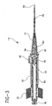
- the needle shield assembly 10 of this invention includes a handle 20, a needle 30, a needle hub 35, a latch 40, a spring 50 and a needle tip guard 60.
- a catheter 70 attached to a catheter hub 75 is located over needle 30.
- Needle hub 35 which can include a flashback chamber, is located inside handle 20.
- a removable vent plug 39 can be placed in the proximal end of needle hub 35. The removability of vent plug 39 allows a syringe or guidewire (not shown) to be inserted through needle hub 35 and needle 30 into a patient to facilitate placement of catheter 70 into the patient or to otherwise treat the patient.
- Needle 30 has a sharp distal tip and is connected at its proximal end to needle hub 35 so that when needle hub 35 is adjacent to the distal end of handle 20, the sharp distal tip of needle 30 extends beyond the distal end of handle 20.
- Spring 50 is located about needle 30 and between the distal end of handle 20 and needle hub 35 to urge needle 30 toward the proximal end of handle 20.
- Latch 40 preferably defines a keyhole opening through which needle hub 35 extends so that latch 40 engages needle hub 35 when needle hub 35 is adjacent to the distal end of handle 20 to hold needle hub 35 against the bias of spring 50.
- latch 40 can be depressed to allow spring 50 to urge needle hub 35, and thus needle 30, toward the proximal end of handle 20. This withdraws needle 30 into handle 20.
- Such a latch is disclosed in pending U.S. patent application Serial No. 08/364,635 filed on December 27, 1994, published as US 5,501,675, the disclosure of which is hereby expressly incorporated by reference.
- Handle 20 has a distal portion 21 and a proximal portion 22.
- Distal portion 21 is formed from a relatively rigid material such as polycarbonate, however, any clean, rigid, medical grade plastic is acceptable. Distal portion 21 should be long enough to house spring 50 and permit viewing of flashback in the flashback chamber portion of needle hub 35.
- Proximal portion 22 is collapsible and non-elastic. The material used for proximal portion 22 must be sufficiently flexible to allow it to be stored and used in the collapsed state and thereafter to extend but not stretch significantly when the medical technician desires to shield needle 30 in handle 20. In one embodiment shown in FIGS. 1-6, proximal portion 22 is formed from a flexible, impermeable, non-elastic material with low elongation characteristics. Acceptable materials for proximal portion 22 include, polyester, canvas, cloth or thin, flexible metal. Proximal portion 22 is bonded to distal portion 21 by any suitable means such as by using a force fit, ultrasonic welding or the use of a
- proximal portion 22 When needle hub 35 is adjacent to the distal end of handle 20, proximal portion 22 can be collapsed to thereby minimize the length of proximal portion 22. As seen in FIG. 3, proximal portion 22 preferably has a bellows configuration to facilitate collapsing and extending thereof. It is to be understood that other configurations for proximal portion 22 are acceptable. With proximal portion 22 in its collapsed condition, handle 20 is easier to manipulate when catheter 70 is inserted into a patient via needle 30. After needle 30 has been used to place catheter 70 into a patient and latch 40 is depressed to allow needle 30 to be retracted into handle 20, proximal portion 22 extends as needle hub 35 moves proximally.
- Proximal portion 22 must have a sufficient length in its fully extended position to allow the sharp distal tip of needle 30 to be withdrawn inside distal portion 21 of handle 20 but must not be too long and must not stretch so as to allow the sharp distal tip of needle 30 to be withdrawn into proximal portion 22. If proximal portion 22 were too long in its fully extended position or if proximal portion 22 were to unduly stretch, the sharp distal tip of needle 30 could become adjacent to proximal portion 22 raising the possibility that needle 30 could puncture the material of proximal portion 22 and expose needle 30.
- the proximal end of proximal portion 22 is preferably bonded directly to the proximal portion of needle hub 35.
- Needle tip guard 60 is securely mounted in distal portion 21 of handle 20.
- Needle tip guard 60 is formed from a resilient material, preferably a stainless steel shim, and includes a mounting leg 64 and a shielding leg 66.
- Mounting leg 64 preferably defines a hole through which needle 30 passes.
- shielding leg 66 is in sliding engagement with the shaft of needle 30 so as to be biased toward the portion of distal portion 21 to which mounting leg 64 is mounted.
- the distal tip thereof will move proximally of shielding leg 66 of needle tip guard 60.
- shielding leg 66 will resiliently move toward an undeflected condition and will safely cover the sharp distal tip of needle 20.
- needle 30 could be moved further proximally so as to be proximal of mounting leg 64.
- shielding leg 66 of needle tip guard 60 any distal movement of needle 30 relative to handle 20 that could conceivably re-expose needle 30 is prevented by shielding leg 66 of needle tip guard 60.
- proximal portion 22 of handle 20 is formed from a telescoping tube 26 that engages a slidable portion 36 of needle hub 35.
- Slidable portion 36 includes a tongue portion that engages a slot 37 formed in the outer wall of needle hub 35 to allow slidable portion 36 to slide along substantially the entire length of needle hub 35.
- tube 26 and slidable portion 36 are formed from stainless steel although other materials such as rigid plastics could be used.
- Tube 26 and slidable portion 36 each have a wall thickness selected to prevent kinking during the shielding operation, and to ensure smooth telescoping movement. A small wall thickness such as between about 0.0051 cm (0.002 inches) to about 0.0127 cm (0.005 inches) is acceptable.
- the distal end of tube 26 is connected directly to the proximal end of distal portion 21. As shown in FIGS. 7 and 8, tube 26 could be threaded onto distal portion 21. Alternative bonding methods could be used or tube 26 and distal portion 21 could be formed as one piece.
- the proximal end of tube 26 includes an inwardly extending locking flange 26a.
- the distal end of slidable portion 36 includes an outwardly extending locking flange 36a.
- slot 37 includes a stop at its distal end to prevent continued movement of slidable portion 36.
- This particular configuration for the second embodiment minimizes the number of pieces needed to manufacture needle shield assembly 10 and minimizes its bulk.
- a plurality of nested telescoping tubes could be used to form proximal portion 22 with one end of the plurality of nested telescoping tubes affixed to distal portion 21 and the other end affixed to needle hub 35.
- the plurality of nested telescoping tubes would be connected to one another by flanges similar to flanges 26a and 36a shown in the second embodiment of FIGS. 7 and 8. It is to be understood that any number of tubes could be used and the telescoping tubes could be telescoped inside of or outside of distal portion 21. The number of tubes chosen will affect the length and diameter of handle 20 when proximal portion 22 is in the collapsed condition for insertion of needle 20 into a patient.
- a needle shield assembly is provided that is not bulky, that is simple and easy to use and that completely covers the entire needle as well as the sharp distal tip after use.
Description
Claims (5)
- A needle shield (10) comprising:characterised in that :a needle (30) having a sharp distal tip and a proximal end;a needle hub (35) having a proximal end and a distal end affixed to the proximal end of the needle (30);a generally hollow handle (20) having a proximal portion and a distal portion, one of the proximal portion or the distal portion being collapsible and non-elastic, the needle hub (35) being disposed in and affixed to the generally hollow handle (20);a spring (50) engaged with the needle hub (35) to bias the needle hub (35) toward the proximal portion of the handle (20);a moveable latch (40) engaged with the needle hub (35) to hold the needle hub (35) against the bias of the spring (50)the shield additionally comprises a flexible tip guard (60) affixed to the distal portion of the handle biased for covering the sharp distal tip of the needle (30) and preventing relative distal movement of the needle (30) after the needle (30) has been withdrawn into the handle (20).
- The needle shield of Claim 1 wherein the proximal portion of the hollow handle (20) is collapsible and non-elastic and the needle hub (35) is affixed to the proximal portion of the hollow handle (20).
- The needle shield of Claim 2 wherein the proximal portion of the handle (20) is formed from an impermeable flexible material.
- The needle shield of Claim 2 wherein the proximal portion is formed from a tube in sliding relation to the distal portion for telescoping movement between a collapsed condition where the distal end of the needle (30) is exposed and an extended condition where the distal end of the needle (30) is surrounded by the shield (10).
- The needle shield of Claim 4, wherein the proximal portion and the distal portion are movingly interlocked with one another for preventing complete separation of the proximal portion and the distal portion.
Applications Claiming Priority (2)
| Application Number | Priority Date | Filing Date | Title |
|---|---|---|---|
| US53157695A | 1995-09-18 | 1995-09-18 | |
| US531576 | 1995-09-18 |
Publications (2)
| Publication Number | Publication Date |
|---|---|
| EP0763369A1 EP0763369A1 (en) | 1997-03-19 |
| EP0763369B1 true EP0763369B1 (en) | 2002-01-09 |
Family
ID=24118209
Family Applications (1)
| Application Number | Title | Priority Date | Filing Date |
|---|---|---|---|
| EP96306465A Expired - Lifetime EP0763369B1 (en) | 1995-09-18 | 1996-09-05 | Needle shield with collapsible cover |
Country Status (6)
| Country | Link |
|---|---|
| US (1) | US5695474A (en) |
| EP (1) | EP0763369B1 (en) |
| JP (1) | JP3174278B2 (en) |
| CA (1) | CA2185187A1 (en) |
| DE (1) | DE69618405T2 (en) |
| ES (1) | ES2171213T3 (en) |
Cited By (12)
| Publication number | Priority date | Publication date | Assignee | Title |
|---|---|---|---|---|
| US6656158B2 (en) | 2002-04-23 | 2003-12-02 | Insulet Corporation | Dispenser for patient infusion device |
| US6656159B2 (en) | 2002-04-23 | 2003-12-02 | Insulet Corporation | Dispenser for patient infusion device |
| US6669669B2 (en) | 2001-10-12 | 2003-12-30 | Insulet Corporation | Laminated patient infusion device |
| US6692457B2 (en) | 2002-03-01 | 2004-02-17 | Insulet Corporation | Flow condition sensor assembly for patient infusion device |
| US6699218B2 (en) | 2000-11-09 | 2004-03-02 | Insulet Corporation | Transcutaneous delivery means |
| US6723072B2 (en) | 2002-06-06 | 2004-04-20 | Insulet Corporation | Plunger assembly for patient infusion device |
| US6749587B2 (en) | 2001-02-22 | 2004-06-15 | Insulet Corporation | Modular infusion device and method |
| US6768425B2 (en) | 2000-12-21 | 2004-07-27 | Insulet Corporation | Medical apparatus remote control and method |
| US6830558B2 (en) | 2002-03-01 | 2004-12-14 | Insulet Corporation | Flow condition sensor assembly for patient infusion device |
| EP2143456A1 (en) | 2008-07-08 | 2010-01-13 | Kunststofftechnik Waidhofen an der Thaya GmbH | Cannula protection and disposable injection system |
| CN108525102A (en) * | 2017-03-01 | 2018-09-14 | C·R·巴德股份有限公司 | Catheter insertion apparatus |
| TWI688416B (en) * | 2019-08-21 | 2020-03-21 | 林忠信 | Syringe |
Families Citing this family (164)
| Publication number | Priority date | Publication date | Assignee | Title |
|---|---|---|---|---|
| US5685855A (en) * | 1996-07-23 | 1997-11-11 | Erskine; Timothy J. | Protected needle catheter placement device with sampling provisions and method for its use |
| US5800395A (en) | 1996-12-05 | 1998-09-01 | Mdc Investment Holdings, Inc. | Medical device with retractable needle |
| US7524306B2 (en) * | 1997-11-12 | 2009-04-28 | Mdc Investment Holdings, Inc. | Catheter insertion device with retractable needle |
| US5957892A (en) * | 1998-03-12 | 1999-09-28 | Specialized Health Products, Inc. | Safety catheter insertion apparatus and methods |
| US6001117A (en) * | 1998-03-19 | 1999-12-14 | Indigo Medical, Inc. | Bellows medical construct and apparatus and method for using same |
| US6749588B1 (en) * | 1998-04-09 | 2004-06-15 | Becton Dickinson And Company | Catheter and introducer needle assembly with needle shield |
| US6126637A (en) * | 1998-04-15 | 2000-10-03 | Science Incorporated | Fluid delivery device with collapsible needle cover |
| US6547762B1 (en) * | 1999-05-13 | 2003-04-15 | Mdc Investment Holdings, Inc. | Retractable needle medical device |
| PL345957A1 (en) * | 1998-07-31 | 2002-01-14 | Mdc Invest Holding | Retractable needle medical device |
| US6669671B1 (en) | 1998-12-22 | 2003-12-30 | Owais Mohammad | Retractable needle with dual locking mechanisms |
| US6302868B1 (en) | 1998-12-22 | 2001-10-16 | Owais Mohammad | Retractable hypodermic needle assembly and method of making the same |
| US6379337B1 (en) * | 1998-12-22 | 2002-04-30 | Owais Mohammad M. B. B. S. | Retractable safety needles for medical applications |
| AUPP798998A0 (en) * | 1998-12-31 | 1999-01-28 | Prestidge, Dean Brian | A parenteral catheter assembly |
| JP4348578B2 (en) * | 1999-04-26 | 2009-10-21 | 株式会社ジェイ・エム・エス | Wing needle device |
| US6416497B1 (en) | 1999-08-27 | 2002-07-09 | Dispomedic 2000 Ltd. | Needle protection holder |
| US7029461B2 (en) | 1999-11-04 | 2006-04-18 | Tyco Healthcare Group Lp | Safety shield for medical needles |
| US6254575B1 (en) | 1999-11-04 | 2001-07-03 | Specialized Health Products | Reaccessible medical needle safety devices and methods |
| US6592556B1 (en) | 2000-07-19 | 2003-07-15 | Tyco Healthcare Group Lp | Medical needle safety apparatus and methods |
| US8226617B2 (en) | 1999-11-04 | 2012-07-24 | Tyco Healthcare Group Lp | Safety shield apparatus and mounting structure for use with medical needle devices |
| US6280420B1 (en) | 1999-11-04 | 2001-08-28 | Specialized Health Products | Reaccessible medical needle safety devices and methods |
| US6776775B1 (en) | 1999-12-23 | 2004-08-17 | Owais Mohammad | Hypodermic syringe needle assembly and method of making the same |
| GB0003790D0 (en) | 2000-02-18 | 2000-04-05 | Astrazeneca Uk Ltd | Medical device |
| DE60104466T2 (en) | 2000-04-04 | 2005-08-04 | Nipro Corp. | Indwelling needle assembly |
| US6629958B1 (en) | 2000-06-07 | 2003-10-07 | Ronald P. Spinello | Leak sealing needle |
| US6558354B1 (en) * | 2000-08-04 | 2003-05-06 | Becton Dickinson And Company | Adapter for connecting an introducer needle assembly to a catheter introducer |
| ES2287156T3 (en) | 2000-09-08 | 2007-12-16 | Insulet Corporation | DEVICES AND SYSTEMS FOR THE INFUSION OF A PATIENT. |
| US6500142B1 (en) | 2000-10-04 | 2002-12-31 | Sage Products, Inc. | Covered suction device with closure |
| JP2002119589A (en) * | 2000-10-18 | 2002-04-23 | Nipro Corp | Dwelling needle assembly |
| JP4013239B2 (en) * | 2000-10-23 | 2007-11-28 | ニプロ株式会社 | Indwelling needle assembly |
| US6461362B1 (en) | 2001-04-30 | 2002-10-08 | Mdc Investment Holdings, Inc. | Catheter insertion device with retractable needle |
| US6773417B2 (en) * | 2001-07-06 | 2004-08-10 | Ispg, Inc. | Epidural space locating device |
| EP1425577A4 (en) * | 2001-08-10 | 2004-12-29 | Symyx Technologies Inc | Apparatuses and methods for creating and testing pre-formulations and systems for same |
| US8066678B2 (en) | 2001-12-17 | 2011-11-29 | Bard Access Systems, Inc. | Safety needle with collapsible sheath |
| US7001363B2 (en) | 2002-04-05 | 2006-02-21 | F. Mark Ferguson | Safety shield for medical needles |
| EP2298404B1 (en) * | 2002-06-20 | 2016-08-10 | Becton Dickinson and Company | Catheter and introducer needle assembly with needle shield |
| ES2763438T3 (en) * | 2002-06-20 | 2020-05-28 | Becton Dickinson Co | Catheter and introducer needle assembly with needle protection |
| JP4496075B2 (en) * | 2002-06-21 | 2010-07-07 | ベクトン・ディキンソン・アンド・カンパニー | Induction needle assembly design method and assembly |
| JP3808806B2 (en) | 2002-06-26 | 2006-08-16 | メディキット株式会社 | Indwelling needle |
| US7128727B2 (en) * | 2002-09-30 | 2006-10-31 | Flaherty J Christopher | Components and methods for patient infusion device |
| WO2004032995A2 (en) * | 2002-10-10 | 2004-04-22 | Becton, Dickinson And Company | Method of delivering local anesthesia |
| US6814725B2 (en) | 2002-11-20 | 2004-11-09 | Raymond Gutierrez | I.V. catheter assembly with blood exposure prevention |
| US7125396B2 (en) * | 2002-12-30 | 2006-10-24 | Cardinal Health 303, Inc. | Safety catheter system and method |
| JP4648615B2 (en) * | 2003-04-04 | 2011-03-09 | 株式会社ジェイ・エム・エス | Medical needle device with a winged shield |
| WO2005016438A1 (en) * | 2003-07-17 | 2005-02-24 | Garry Tsaur | Retractable packaging |
| US7513888B2 (en) * | 2004-02-17 | 2009-04-07 | Smiths Medical Asd, Inc. | Needle guards |
| US7776016B1 (en) | 2004-02-26 | 2010-08-17 | C. R. Bard, Inc. | Huber needle safety enclosure |
| FR2867081B1 (en) * | 2004-03-02 | 2006-05-26 | Vygon | SLIDING SAFETY DEVICE FOR PLACING A CANNULA INTO A VEIN |
| EP1755714A1 (en) * | 2004-05-14 | 2007-02-28 | Safety Medical Products Limited | Improved syringe with retractable needle |
| WO2006032995A2 (en) * | 2004-09-24 | 2006-03-30 | Tecnomedica S.R.L. | Cannula device |
| US9162037B2 (en) | 2005-07-06 | 2015-10-20 | Vascular Pathways, Inc. | Intravenous catheter insertion device and method of use |
| US7632243B2 (en) * | 2005-08-08 | 2009-12-15 | Smiths Medical Asd, Inc. | Duckbill catheter release mechanism |
| US8162881B2 (en) * | 2005-08-08 | 2012-04-24 | Smiths Medical Asd, Inc. | Needle guard mechanism with angled strut wall |
| US7597681B2 (en) * | 2005-08-08 | 2009-10-06 | Smiths Medical Asd, Inc. | Needle guard mechanism with shroud |
| US7753877B2 (en) * | 2005-08-08 | 2010-07-13 | Smiths Medical Asd, Inc. | Needle guard strut wall clip |
| US8403886B2 (en) * | 2005-08-08 | 2013-03-26 | Smiths Medical Asd, Inc. | Needle guard clip with lip |
| US7682341B2 (en) | 2005-11-09 | 2010-03-23 | Medikit Co., Ltd | Indwelling needle |
| ATE433774T1 (en) * | 2005-11-10 | 2009-07-15 | Medikit Co Ltd | lingering needle |
| JP4714011B2 (en) * | 2005-11-28 | 2011-06-29 | メディキット株式会社 | Indwelling needle assembly |
| US8834407B2 (en) * | 2006-01-20 | 2014-09-16 | Medline Industries, Inc. | Covered yankauer suction device and methods of using same |
| US20070191777A1 (en) * | 2006-02-16 | 2007-08-16 | Medex, Inc. | Enclosed Needle Device with Fluid Path Access |
| US7658725B2 (en) * | 2006-02-16 | 2010-02-09 | Smiths Medical Asd, Inc. | Enclosed needle device with duckbill release mechanism |
| US8496627B2 (en) | 2006-03-21 | 2013-07-30 | Covidien Lp | Passive latch ring safety shield for injection devices |
| WO2007121505A1 (en) * | 2006-04-24 | 2007-11-01 | Analytica Limited | A needle assembly |
| US10085884B2 (en) | 2006-06-30 | 2018-10-02 | Aquesys, Inc. | Intraocular devices |
| US8828070B2 (en) | 2010-11-15 | 2014-09-09 | Aquesys, Inc. | Devices for deploying intraocular shunts |
| US8308701B2 (en) | 2010-11-15 | 2012-11-13 | Aquesys, Inc. | Methods for deploying intraocular shunts |
| US8852137B2 (en) | 2010-11-15 | 2014-10-07 | Aquesys, Inc. | Methods for implanting a soft gel shunt in the suprachoroidal space |
| US8801766B2 (en) | 2010-11-15 | 2014-08-12 | Aquesys, Inc. | Devices for deploying intraocular shunts |
| EP2043572B1 (en) * | 2006-06-30 | 2014-12-31 | Aquesys Inc. | Apparatus for relieving pressure in an organ |
| US8852256B2 (en) | 2010-11-15 | 2014-10-07 | Aquesys, Inc. | Methods for intraocular shunt placement |
| US20120123316A1 (en) | 2010-11-15 | 2012-05-17 | Aquesys, Inc. | Intraocular shunts for placement in the intra-tenon's space |
| US8663303B2 (en) | 2010-11-15 | 2014-03-04 | Aquesys, Inc. | Methods for deploying an intraocular shunt from a deployment device and into an eye |
| US8974511B2 (en) | 2010-11-15 | 2015-03-10 | Aquesys, Inc. | Methods for treating closed angle glaucoma |
| US9095411B2 (en) | 2010-11-15 | 2015-08-04 | Aquesys, Inc. | Devices for deploying intraocular shunts |
| US8758290B2 (en) | 2010-11-15 | 2014-06-24 | Aquesys, Inc. | Devices and methods for implanting a shunt in the suprachoroidal space |
| US8721702B2 (en) | 2010-11-15 | 2014-05-13 | Aquesys, Inc. | Intraocular shunt deployment devices |
| JP5108882B2 (en) * | 2006-07-06 | 2012-12-26 | バスキュラー・パスウェイズ・インコーポレイテッド | Venous catheter insertion device |
| US20080033370A1 (en) | 2006-08-03 | 2008-02-07 | Becton, Dickinson And Company | Binary needle attachment mechanisms |
| JP4994775B2 (en) | 2006-10-12 | 2012-08-08 | 日本コヴィディエン株式会社 | Needle point protector |
| US8057431B2 (en) | 2006-12-21 | 2011-11-15 | B. Braun Melsungen Ag | Hinged cap for needle device |
| ES2800176T3 (en) | 2007-03-07 | 2020-12-28 | Becton Dickinson Co | Blood collection safety kit with indicator |
| US8888713B2 (en) * | 2007-03-07 | 2014-11-18 | Becton, Dickinson And Company | Safety blood collection assembly with indicator |
| US8597253B2 (en) | 2007-04-20 | 2013-12-03 | Bard Access Systems | Huber needle with safety sheath |
| EP2272432B1 (en) * | 2007-05-07 | 2012-03-14 | Vascular Pathways Inc. | Intravenous catheter insertion and blood sample devices |
| US7736342B2 (en) * | 2007-05-30 | 2010-06-15 | Smiths Medical Asd, Inc. | Enclosed needle cannula device with proximal end cap |
| US8603009B2 (en) | 2008-03-07 | 2013-12-10 | Becton, Dickinson And Company | Flashback blood collection needle |
| US8795198B2 (en) * | 2008-03-07 | 2014-08-05 | Becton, Dickinson And Company | Flashback blood collection needle |
| JP4533944B2 (en) * | 2008-05-14 | 2010-09-01 | 本田技研工業株式会社 | Instrument panel for vehicle |
| US8231582B2 (en) | 2008-12-11 | 2012-07-31 | Bard Access Systems, Inc. | Device for removing a Huber needle from a patient |
| JP2011045544A (en) * | 2009-08-27 | 2011-03-10 | Terumo Corp | Indwelling needle assembly |
| US9872971B2 (en) | 2010-05-14 | 2018-01-23 | C. R. Bard, Inc. | Guidewire extension system for a catheter placement device |
| US11925779B2 (en) | 2010-05-14 | 2024-03-12 | C. R. Bard, Inc. | Catheter insertion device including top-mounted advancement components |
| US10384039B2 (en) | 2010-05-14 | 2019-08-20 | C. R. Bard, Inc. | Catheter insertion device including top-mounted advancement components |
| US9950139B2 (en) | 2010-05-14 | 2018-04-24 | C. R. Bard, Inc. | Catheter placement device including guidewire and catheter control elements |
| US8932258B2 (en) | 2010-05-14 | 2015-01-13 | C. R. Bard, Inc. | Catheter placement device and method |
| WO2012023938A1 (en) | 2010-08-19 | 2012-02-23 | West Pharmaceutical Services, Inc. | Rigid needle shield |
| US20140066894A1 (en) | 2010-09-10 | 2014-03-06 | C. R. Bard, Inc. | Self-Sealing Pad for a Needle-Based Infusion Set |
| US10525234B2 (en) | 2010-09-10 | 2020-01-07 | C. R. Bard, Inc. | Antimicrobial/haemostatic interface pad for placement between percutaneously placed medical device and patient skin |
| CA2806393A1 (en) | 2010-09-10 | 2012-03-15 | C.R. Bard, Inc. | Systems for isolation of a needle-based infusion set |
| US20160256317A1 (en) | 2010-11-15 | 2016-09-08 | Aquesys, Inc. | Methods for implanting intraocular shunts |
| US8585629B2 (en) | 2010-11-15 | 2013-11-19 | Aquesys, Inc. | Systems for deploying intraocular shunts |
| WO2012068132A1 (en) * | 2010-11-15 | 2012-05-24 | Aquesys, Inc. | Devices for deploying intraocular shunts |
| US8690833B2 (en) | 2011-01-31 | 2014-04-08 | Vascular Pathways, Inc. | Intravenous catheter and insertion device with reduced blood spatter |
| ES2750035T3 (en) | 2011-02-25 | 2020-03-24 | Bard Inc C R | Medical component insertion device including a retractable needle |
| US8486024B2 (en) | 2011-04-27 | 2013-07-16 | Covidien Lp | Safety IV catheter assemblies |
| USD903101S1 (en) | 2011-05-13 | 2020-11-24 | C. R. Bard, Inc. | Catheter |
| WO2013032779A2 (en) | 2011-08-26 | 2013-03-07 | Eli Lilly And Company | Refill module for an injection device |
| WO2013048975A1 (en) | 2011-09-26 | 2013-04-04 | Covidien Lp | Safety catheter |
| EP2760521B1 (en) | 2011-09-26 | 2016-01-06 | Covidien LP | Safety iv catheter and needle assembly |
| US8834422B2 (en) | 2011-10-14 | 2014-09-16 | Covidien Lp | Vascular access assembly and safety device |
| AU2012335825B2 (en) | 2011-11-07 | 2017-02-16 | Safety Syringes, Inc. | Contact trigger release needle guard |
| US9610195B2 (en) | 2013-02-27 | 2017-04-04 | Aquesys, Inc. | Intraocular shunt implantation methods and devices |
| US10080682B2 (en) | 2011-12-08 | 2018-09-25 | Aquesys, Inc. | Intrascleral shunt placement |
| US8765210B2 (en) | 2011-12-08 | 2014-07-01 | Aquesys, Inc. | Systems and methods for making gelatin shunts |
| US9808373B2 (en) | 2013-06-28 | 2017-11-07 | Aquesys, Inc. | Intraocular shunt implantation |
| US8852136B2 (en) | 2011-12-08 | 2014-10-07 | Aquesys, Inc. | Methods for placing a shunt into the intra-scleral space |
| MX2011013382A (en) | 2011-12-12 | 2013-06-20 | Equipos Medicos Vizcarra S A | Safety peripheral intravenous catheter having a quick, painless puncture system. |
| WO2013149186A1 (en) | 2012-03-30 | 2013-10-03 | Insulet Corporation | Fluid delivery device with transcutaneous access tool, insertion mechansim and blood glucose monitoring for use therewith |
| US9078981B2 (en) * | 2012-09-21 | 2015-07-14 | Boston Scientific Scimed Inc. | Catheter system including an embolism protection device |
| JP6059497B2 (en) * | 2012-10-03 | 2017-01-11 | メディキット株式会社 | Needle assembly |
| EP2905042B1 (en) * | 2012-10-05 | 2019-05-01 | Medikit Co., Ltd. | Medical safety needle which prevents re-exposure of needle tip |
| WO2014063353A1 (en) * | 2012-10-26 | 2014-05-01 | Zhang Jianming | Puncture needle tube component of indwelling needle with needle tip protective sleeve |
| CN104884104A (en) | 2012-11-29 | 2015-09-02 | 诺和诺德股份有限公司 | Injection device with integrated needle shield |
| CN105102054B (en) | 2013-01-30 | 2018-04-20 | 血管通路股份有限公司 | The system and method placed for venipuncture and conduit |
| MX2013001219A (en) * | 2013-01-30 | 2014-07-30 | Equipos Médicos Vizcarra S A | Closed peripheral intravenous catheter with safety system cpivcss. |
| EP2952220B1 (en) * | 2013-01-30 | 2019-11-13 | Equipos Médicos Vizcarra, S.A. | Peripheral intravenous catheter with bellows-type passive safety system ivcbts |
| US9125723B2 (en) | 2013-02-19 | 2015-09-08 | Aquesys, Inc. | Adjustable glaucoma implant |
| US10159600B2 (en) | 2013-02-19 | 2018-12-25 | Aquesys, Inc. | Adjustable intraocular flow regulation |
| US9585790B2 (en) | 2013-11-14 | 2017-03-07 | Aquesys, Inc. | Intraocular shunt inserter |
| US9555221B2 (en) | 2014-04-10 | 2017-01-31 | Smiths Medical Asd, Inc. | Constant force hold tip protector for a safety catheter |
| WO2016037127A1 (en) | 2014-09-05 | 2016-03-10 | C.R. Bard, Inc. | Catheter insertion device including retractable needle |
| USD903100S1 (en) | 2015-05-01 | 2020-11-24 | C. R. Bard, Inc. | Catheter placement device |
| JP7016261B2 (en) | 2015-05-15 | 2022-02-21 | シー・アール・バード・インコーポレーテッド | Catheter indwelling device with extendable needle safety component |
| BR112017025859A2 (en) | 2015-06-03 | 2018-08-14 | Aquesys, Inc. | external ab intraocular shunt placement |
| CN105056329B (en) * | 2015-07-28 | 2018-11-06 | 王维文 | A kind of medicine dissolving device |
| CN105214176B (en) * | 2015-09-10 | 2019-03-05 | 宁波市鄞州扬锐医用工程有限公司 | A kind of safety syringe-drum with telescopic protective cover |
| EP3377133B1 (en) | 2015-11-20 | 2021-07-14 | Tc1 Llc | System architecture that allows patient replacement of vad controller/interface module without disconnection of old module |
| EP3677226B1 (en) | 2015-11-20 | 2021-12-22 | Tc1 Llc | Improved connectors and cables for use with ventricle assist systems |
| EP3711788B1 (en) | 2015-11-20 | 2022-08-03 | Tc1 Llc | Blood pump controllers having daisy-chained batteries |
| EP3377136B1 (en) | 2015-11-20 | 2020-05-06 | Tc1 Llc | Energy management of blood pump controllers |
| EP3380061A4 (en) | 2015-11-24 | 2019-07-24 | Insulet Corporation | Wearable automated medication delivery system |
| WO2017091584A1 (en) | 2015-11-25 | 2017-06-01 | Insulet Corporation | Wearable medication delivery device |
| WO2017210627A1 (en) | 2016-06-02 | 2017-12-07 | Aquesys, Inc. | Intraocular drug delivery |
| JP7021180B2 (en) * | 2016-07-14 | 2022-02-16 | サノフィ-アベンティス・ドイチュラント・ゲゼルシャフト・ミット・ベシュレンクテル・ハフツング | Body arrangement for drug delivery device |
| WO2018049413A1 (en) | 2016-09-12 | 2018-03-15 | C.R. Bard, Inc. | Blood control for a catheter insertion device |
| WO2018156548A1 (en) | 2017-02-22 | 2018-08-30 | Insulet Corporation | Needle insertion mechanisms for drug containers |
| US10603446B2 (en) * | 2017-04-03 | 2020-03-31 | Becton, Dickinson And Company | IV catheter with integral extension set and a spring powered needle safety |
| US11147957B2 (en) * | 2017-07-19 | 2021-10-19 | Becton, Dickinson And Company | Systems and methods to improve instrument guidance within an intravenous catheter assembly |
| WO2019067367A1 (en) | 2017-09-26 | 2019-04-04 | Insulet Corporation | Needle mechanism module for drug delivery device |
| US11246753B2 (en) | 2017-11-08 | 2022-02-15 | Aquesys, Inc. | Manually adjustable intraocular flow regulation |
| US11147931B2 (en) | 2017-11-17 | 2021-10-19 | Insulet Corporation | Drug delivery device with air and backflow elimination |
| US11389626B2 (en) | 2018-03-07 | 2022-07-19 | Bard Access Systems, Inc. | Guidewire advancement and blood flashback systems for a medical device insertion system |
| US11135089B2 (en) | 2018-03-09 | 2021-10-05 | Aquesys, Inc. | Intraocular shunt inserter |
| US10952898B2 (en) | 2018-03-09 | 2021-03-23 | Aquesys, Inc. | Intraocular shunt inserter |
| US11389641B2 (en) | 2018-03-21 | 2022-07-19 | Tc1 Llc | Modular flying lead cable and methods for use with heart pump controllers |
| US10953145B2 (en) | 2018-03-21 | 2021-03-23 | Tci Llc | Driveline connectors and methods for use with heart pump controllers |
| EP3787707B1 (en) | 2018-04-30 | 2023-12-27 | Tc1 Llc | Improved blood pump connectors |
| US11224736B2 (en) | 2018-05-31 | 2022-01-18 | Tc1 Llc | Blood pump controllers |
| EP3758612B1 (en) * | 2018-06-20 | 2023-04-19 | Boston Scientific Scimed, Inc. | Sheath for enabling needle exchange and needle-sharp safety |
| US11097083B2 (en) | 2018-07-17 | 2021-08-24 | Becton, Dickinson And Company | Systems and methods to improve instrument guidance within an intravenous catheter assembly |
| USD921884S1 (en) | 2018-07-27 | 2021-06-08 | Bard Access Systems, Inc. | Catheter insertion device |
| CN213312819U (en) | 2019-08-19 | 2021-06-01 | 贝克顿·迪金森公司 | Midline catheter placement device |
| US20210212618A1 (en) * | 2020-01-09 | 2021-07-15 | Becton, Dickinson And Company | Extension set for improving patency of a vascular access device |
| US20210290914A1 (en) * | 2020-03-23 | 2021-09-23 | Becton, Dickinson And Company | Vascular access device assembly facilitating single-handed probe advancement with a support member |
Family Cites Families (35)
| Publication number | Priority date | Publication date | Assignee | Title |
|---|---|---|---|---|
| US3867937A (en) * | 1972-12-07 | 1975-02-25 | Boris Schwartz | Flexible protective sheath for catheter |
| US3994295A (en) * | 1975-08-22 | 1976-11-30 | Wulff Goldwyn L | Hypodermic syringe needle mounting |
| US4702737A (en) * | 1986-07-14 | 1987-10-27 | Pizzino Joanne L | Dual dose syringe |
| US4731059A (en) * | 1986-10-14 | 1988-03-15 | Medical Safety Products, Inc. | Combination needle shield/needle guard device positively locked onto detachable needle assemblies for an evacuated blood collection system and a hypodermic syringe |
| US4832696A (en) * | 1987-03-05 | 1989-05-23 | Luther Medical Products, Inc. | Assembly of needle and protector |
| US4762516A (en) * | 1987-03-05 | 1988-08-09 | Luther Medical Products, Inc. | Assembly of needle catheter protector |
| US4747831A (en) * | 1987-04-29 | 1988-05-31 | Phase Medical, Inc. | Cannula insertion set with safety retracting needle |
| US4725267A (en) * | 1987-05-06 | 1988-02-16 | Vaillancourt Vincent L | Post-injection needle sheath |
| US4834718A (en) * | 1987-06-01 | 1989-05-30 | Michael McDonald | Safety needle apparatus |
| US4804372A (en) * | 1987-09-08 | 1989-02-14 | Laico Joseph P | Protective sheath for hypodermic needle |
| US4950252A (en) * | 1987-11-02 | 1990-08-21 | Luther Medical Products, Inc. | Single hand actuated locking safety catheter and method of use |
| US4927416A (en) * | 1987-12-02 | 1990-05-22 | National Medical Device Corporation | User-protective hypodermic syringe holder |
| US4846805A (en) * | 1987-12-04 | 1989-07-11 | Icu Medical, Inc. | Catheter insert device |
| US4935013A (en) * | 1988-02-23 | 1990-06-19 | Habley Medical Technology Corporation | Collapsible needle cover |
| US4950250A (en) * | 1988-02-23 | 1990-08-21 | Habley Medical Technology Corporation | Collapsible needle cover |
| US4897083A (en) * | 1988-05-09 | 1990-01-30 | Martell Michael D | Syringe needle guard |
| US4978344A (en) * | 1988-08-11 | 1990-12-18 | Dombrowski Mitchell P | Needle and catheter assembly |
| CA1315166C (en) * | 1988-10-05 | 1993-03-30 | John S. Parry | Injection devices |
| US4944728A (en) * | 1988-10-17 | 1990-07-31 | Safe Medical Devices, Inc. | Intravenous catheter placement device |
| US4921491A (en) * | 1989-04-03 | 1990-05-01 | Champ Raynido A | Disposable needle system with chemical disinfectant means |
| US5219338A (en) * | 1990-01-18 | 1993-06-15 | Haworth Warren D | Safety syringe with collapsible needle guard |
| US5106379A (en) * | 1991-04-09 | 1992-04-21 | Leap E Jack | Syringe shielding assembly |
| US5273540A (en) * | 1991-04-26 | 1993-12-28 | Luther Medical Products | Nonreusable needle and catheter assembly |
| IT1251532B (en) * | 1991-10-31 | 1995-05-16 | Pasquale Mastronardi | NEEDLE CANNULA PROVIDED WITH SAFETY DEVICE |
| AU3245393A (en) * | 1991-12-09 | 1993-07-19 | Square One Medical | Rotary lock for needle sheaths |
| AU651745B2 (en) * | 1991-12-13 | 1994-07-28 | Covidien Ag | Locking pneumoneedle |
| US5242416A (en) * | 1992-01-09 | 1993-09-07 | Hutson Clifford L | Shield assembly for needle syringes |
| US5304136A (en) * | 1992-02-07 | 1994-04-19 | Becton, Dickinson And Company | Needle sheath |
| AU3997493A (en) * | 1992-06-05 | 1993-12-09 | Critikon, Inc. | Catheter with needle guard and extended flash chamber |
| AU4131793A (en) * | 1992-06-26 | 1994-01-06 | Critikon, Inc. | Catheter with extensible, two-piece needle guard |
| US5332092A (en) * | 1993-02-16 | 1994-07-26 | Ultradent Products, Inc. | Protective syringe sheath and method of use |
| US5334149A (en) * | 1993-07-13 | 1994-08-02 | Marvin Nortman | Post-injection sheath for a hypodermic syringe needle |
| US5376075A (en) * | 1993-08-31 | 1994-12-27 | Haughton; Victor M. | Catheter sharp retraction system |
| US5419766A (en) * | 1993-09-28 | 1995-05-30 | Critikon, Inc. | Catheter with stick protection |
| US5336199A (en) * | 1993-11-12 | 1994-08-09 | Castillo Leo S | Medical needle and needle sheath assembly |
-
1996
- 1996-09-05 DE DE69618405T patent/DE69618405T2/en not_active Expired - Fee Related
- 1996-09-05 ES ES96306465T patent/ES2171213T3/en not_active Expired - Lifetime
- 1996-09-05 EP EP96306465A patent/EP0763369B1/en not_active Expired - Lifetime
- 1996-09-10 CA CA002185187A patent/CA2185187A1/en not_active Abandoned
- 1996-09-18 JP JP24626996A patent/JP3174278B2/en not_active Expired - Lifetime
-
1997
- 1997-01-09 US US08/781,549 patent/US5695474A/en not_active Expired - Fee Related
Cited By (15)
| Publication number | Priority date | Publication date | Assignee | Title |
|---|---|---|---|---|
| US6699218B2 (en) | 2000-11-09 | 2004-03-02 | Insulet Corporation | Transcutaneous delivery means |
| US6768425B2 (en) | 2000-12-21 | 2004-07-27 | Insulet Corporation | Medical apparatus remote control and method |
| US6749587B2 (en) | 2001-02-22 | 2004-06-15 | Insulet Corporation | Modular infusion device and method |
| US6669669B2 (en) | 2001-10-12 | 2003-12-30 | Insulet Corporation | Laminated patient infusion device |
| US6692457B2 (en) | 2002-03-01 | 2004-02-17 | Insulet Corporation | Flow condition sensor assembly for patient infusion device |
| US6830558B2 (en) | 2002-03-01 | 2004-12-14 | Insulet Corporation | Flow condition sensor assembly for patient infusion device |
| US7887505B2 (en) | 2002-03-01 | 2011-02-15 | Insulet Corporation | Flow condition sensor assembly for patient infusion device |
| US6656158B2 (en) | 2002-04-23 | 2003-12-02 | Insulet Corporation | Dispenser for patient infusion device |
| US6656159B2 (en) | 2002-04-23 | 2003-12-02 | Insulet Corporation | Dispenser for patient infusion device |
| US6723072B2 (en) | 2002-06-06 | 2004-04-20 | Insulet Corporation | Plunger assembly for patient infusion device |
| EP2143456A1 (en) | 2008-07-08 | 2010-01-13 | Kunststofftechnik Waidhofen an der Thaya GmbH | Cannula protection and disposable injection system |
| WO2010003829A1 (en) | 2008-07-08 | 2010-01-14 | Kunststofftechnik Waidhofen An Der Thaya Gmbh | Cannula protector and single-use syringe system |
| CN108525102A (en) * | 2017-03-01 | 2018-09-14 | C·R·巴德股份有限公司 | Catheter insertion apparatus |
| CN108525102B (en) * | 2017-03-01 | 2022-01-11 | C·R·巴德股份有限公司 | Catheter insertion device |
| TWI688416B (en) * | 2019-08-21 | 2020-03-21 | 林忠信 | Syringe |
Also Published As
| Publication number | Publication date |
|---|---|
| DE69618405T2 (en) | 2002-08-01 |
| CA2185187A1 (en) | 1997-03-19 |
| JPH09103492A (en) | 1997-04-22 |
| DE69618405D1 (en) | 2002-02-14 |
| EP0763369A1 (en) | 1997-03-19 |
| US5695474A (en) | 1997-12-09 |
| JP3174278B2 (en) | 2001-06-11 |
| ES2171213T3 (en) | 2002-09-01 |
Similar Documents
| Publication | Publication Date | Title |
|---|---|---|
| EP0763369B1 (en) | Needle shield with collapsible cover | |
| US5792122A (en) | Telescoping needle shield | |
| US5772636A (en) | Catheter assembly with interlocking telescoping needle shield | |
| US7344516B2 (en) | Catheter-advancement actuated needle retraction system | |
| US7291130B2 (en) | Safety needle and catheter assembly | |
| US5795339A (en) | Catheter-advancement actuated needle retraction system | |
| US5865806A (en) | One step catheter advancement automatic needle retraction system | |
| US5549571A (en) | Butterfly assembly with retractable needle cannula | |
| US6730062B2 (en) | Safety catheter with non-removable retractable needle | |
| US6485469B1 (en) | Shielded dental safety needle | |
| JP2010099534A (en) | Compact needle point shield | |
| NZ286744A (en) | Catheter with needle point guard: non-round outer section of needle engages needle guard on withdrawal | |
| AU2006202547A1 (en) | Safety shield for medical needles | |
| CA2663089A1 (en) | Safety needle assembly | |
| US5512050A (en) | Needle assembly with collapsible and retractable sheath | |
| CA2520353C (en) | Safety needle and catheter assembly | |
| US5356387A (en) | Needle guard assembly with drawstring for a syringe | |
| WO2001023028A1 (en) | Catheter and dual feature introducer needle assembly with needle shield |
Legal Events
| Date | Code | Title | Description |
|---|---|---|---|
| PUAI | Public reference made under article 153(3) epc to a published international application that has entered the european phase |
Free format text: ORIGINAL CODE: 0009012 |
|
| AK | Designated contracting states |
Kind code of ref document: A1 Designated state(s): DE ES FR GB IT |
|
| 17P | Request for examination filed |
Effective date: 19970912 |
|
| 17Q | First examination report despatched |
Effective date: 20000223 |
|
| GRAG | Despatch of communication of intention to grant |
Free format text: ORIGINAL CODE: EPIDOS AGRA |
|
| GRAG | Despatch of communication of intention to grant |
Free format text: ORIGINAL CODE: EPIDOS AGRA |
|
| GRAH | Despatch of communication of intention to grant a patent |
Free format text: ORIGINAL CODE: EPIDOS IGRA |
|
| GRAH | Despatch of communication of intention to grant a patent |
Free format text: ORIGINAL CODE: EPIDOS IGRA |
|
| GRAA | (expected) grant |
Free format text: ORIGINAL CODE: 0009210 |
|
| REG | Reference to a national code |
Ref country code: GB Ref legal event code: IF02 |
|
| AK | Designated contracting states |
Kind code of ref document: B1 Designated state(s): DE ES FR GB IT |
|
| REF | Corresponds to: |
Ref document number: 69618405 Country of ref document: DE Date of ref document: 20020214 |
|
| ET | Fr: translation filed | ||
| PGFP | Annual fee paid to national office [announced via postgrant information from national office to epo] |
Ref country code: FR Payment date: 20020819 Year of fee payment: 7 |
|
| PGFP | Annual fee paid to national office [announced via postgrant information from national office to epo] |
Ref country code: GB Payment date: 20020828 Year of fee payment: 7 |
|
| REG | Reference to a national code |
Ref country code: ES Ref legal event code: FG2A Ref document number: 2171213 Country of ref document: ES Kind code of ref document: T3 |
|
| PGFP | Annual fee paid to national office [announced via postgrant information from national office to epo] |
Ref country code: DE Payment date: 20020930 Year of fee payment: 7 |
|
| PGFP | Annual fee paid to national office [announced via postgrant information from national office to epo] |
Ref country code: ES Payment date: 20021009 Year of fee payment: 7 |
|
| PLBE | No opposition filed within time limit |
Free format text: ORIGINAL CODE: 0009261 |
|
| STAA | Information on the status of an ep patent application or granted ep patent |
Free format text: STATUS: NO OPPOSITION FILED WITHIN TIME LIMIT |
|
| 26N | No opposition filed | ||
| PG25 | Lapsed in a contracting state [announced via postgrant information from national office to epo] |
Ref country code: GB Free format text: LAPSE BECAUSE OF NON-PAYMENT OF DUE FEES Effective date: 20030905 |
|
| PG25 | Lapsed in a contracting state [announced via postgrant information from national office to epo] |
Ref country code: ES Free format text: LAPSE BECAUSE OF NON-PAYMENT OF DUE FEES Effective date: 20030906 |
|
| PG25 | Lapsed in a contracting state [announced via postgrant information from national office to epo] |
Ref country code: DE Free format text: LAPSE BECAUSE OF NON-PAYMENT OF DUE FEES Effective date: 20040401 |
|
| GBPC | Gb: european patent ceased through non-payment of renewal fee | ||
| PG25 | Lapsed in a contracting state [announced via postgrant information from national office to epo] |
Ref country code: FR Free format text: LAPSE BECAUSE OF NON-PAYMENT OF DUE FEES Effective date: 20040528 |
|
| REG | Reference to a national code |
Ref country code: FR Ref legal event code: ST |
|
| REG | Reference to a national code |
Ref country code: ES Ref legal event code: FD2A Effective date: 20030906 |
|
| PG25 | Lapsed in a contracting state [announced via postgrant information from national office to epo] |
Ref country code: IT Free format text: LAPSE BECAUSE OF NON-PAYMENT OF DUE FEES Effective date: 20050905 |