EP0764942A1 - Flexible circuit for magnetic head assembly having reduced stiffness area for minimizing the effects of roll and pitch - Google Patents
Flexible circuit for magnetic head assembly having reduced stiffness area for minimizing the effects of roll and pitch Download PDFInfo
- Publication number
- EP0764942A1 EP0764942A1 EP96115327A EP96115327A EP0764942A1 EP 0764942 A1 EP0764942 A1 EP 0764942A1 EP 96115327 A EP96115327 A EP 96115327A EP 96115327 A EP96115327 A EP 96115327A EP 0764942 A1 EP0764942 A1 EP 0764942A1
- Authority
- EP
- European Patent Office
- Prior art keywords
- flex circuit
- slider
- flexure
- transducer
- load beam
- Prior art date
- Legal status (The legal status is an assumption and is not a legal conclusion. Google has not performed a legal analysis and makes no representation as to the accuracy of the status listed.)
- Withdrawn
Links
Images

Classifications
-
- G—PHYSICS
- G11—INFORMATION STORAGE
- G11B—INFORMATION STORAGE BASED ON RELATIVE MOVEMENT BETWEEN RECORD CARRIER AND TRANSDUCER
- G11B5/00—Recording by magnetisation or demagnetisation of a record carrier; Reproducing by magnetic means; Record carriers therefor
- G11B5/48—Disposition or mounting of heads or head supports relative to record carriers ; arrangements of heads, e.g. for scanning the record carrier to increase the relative speed
- G11B5/4806—Disposition or mounting of heads or head supports relative to record carriers ; arrangements of heads, e.g. for scanning the record carrier to increase the relative speed specially adapted for disk drive assemblies, e.g. assembly prior to operation, hard or flexible disk drives
- G11B5/4853—Constructional details of the electrical connection between head and arm
-
- G—PHYSICS
- G11—INFORMATION STORAGE
- G11B—INFORMATION STORAGE BASED ON RELATIVE MOVEMENT BETWEEN RECORD CARRIER AND TRANSDUCER
- G11B5/00—Recording by magnetisation or demagnetisation of a record carrier; Reproducing by magnetic means; Record carriers therefor
- G11B5/48—Disposition or mounting of heads or head supports relative to record carriers ; arrangements of heads, e.g. for scanning the record carrier to increase the relative speed
- G11B5/4806—Disposition or mounting of heads or head supports relative to record carriers ; arrangements of heads, e.g. for scanning the record carrier to increase the relative speed specially adapted for disk drive assemblies, e.g. assembly prior to operation, hard or flexible disk drives
- G11B5/486—Disposition or mounting of heads or head supports relative to record carriers ; arrangements of heads, e.g. for scanning the record carrier to increase the relative speed specially adapted for disk drive assemblies, e.g. assembly prior to operation, hard or flexible disk drives with provision for mounting or arranging electrical conducting means or circuits on or along the arm assembly
Definitions
- This invention relates to magnetic head assemblies used in magnetic disk drive storage systems and in particular to the replacement of the transducer wiring with a flex (flexible) circuit in the head gimbal assembly (HGA) of a head assembly.
- HGA head gimbal assembly
- a disk drive typically includes a number of magnetic disks mounted to a common spindle for rotation. Each magnetic disk surface has an associated head arm assembly which includes a head gimbal assembly.
- the head arm assemblies are generally attached to an actuator for positioning a transducer, which is joined to the head gimbal assemblies, with reference to data tracks on the magnetic disks.
- disk drive manufacturers want the space required for the head gimbal assemblies between adjacent magnetic disk surfaces to be as small as possible.
- a head gimbal assembly is comprised of an air bearing slider on which a magnetic transducer is deposited.
- the slider is attached to a flexure which in turn is attached to a load beam.
- Transducer wires are connected to the transducer.
- the load beam exerts a force on the flexure/slider combination towards the surface of a disk.
- ABS air bearing surface
- the transducer can be a inductive type transducer which requires two transducer wires or a magnetoresistive type transducer which requires four or more transducer wires.
- the transducer preferably is a thin film transducer which is deposited directly onto the slider. Over time the size of the slider has been reduced allowing the data track density on the magnetic disks to be increased thereby resulting in an increased storage capacity for a disk drive system having the same size magnetic disk.
- the slider size has decreased from a standard size, i.e., 0.160 inch long, 0.125 inch wide, and 0.0345 inch high, to a macro size (70% of standard), then to a nano size (50% of standard) and now to a pico size (25-35% of standard).
- the stiffness of a wire is a function of the diameter, i.e. gauge of the wire and the length of the wire. As the wire length becomes shorter, the stiffness of the wire increases. As the diameter of the wire decreases, the resistivity of the wire increases resulting in a decrease in the signal-to-noise ratio, and the stiffness decreases for a given length of wire. Where a wire is bonded along the wire's length at several locations, the length of the wire defines the stiffness of the wire between two adjacent bonding points.
- a transducer wire is attached to a bonding pad on the slider and to a point on the load beam.
- the stiffness of the transducer wire places stress on the bond between the bonding wire and the bonding pad, and adversely affects the freedom of movement of the flexure/slider combination and the overall flying characteristics of the slider.
- the prior art has increased the length of the transducer wires as much as possible to form a loop between the bonding point of the transducer wires on the load beam and the bonding pads on the slider. This loop is referred to as a service loop.
- transducer wires used with inductive type transducers were commonly 44 gauge, had a wire diameter of 0.002 inch, and had a service loop length of 0.2 inch which yielded a relative stiffness of 0.5 for the two transducer wires.
- the transducer wires used with inductive type transducers were commonly reduced to 48 gauge, a wire diameter of 0.0012 inch, and had a service loop length of 0.15 inch which yielded a relative stiffness of 0.36 for the two transducer wires.
- the four transducer wires are made of 48 gauge, with a wire diameter of 0.0012 inch, and a service loop length of 0.15 inch. This results in the undesirable relative stiffness of 0.73 for the four transducer wires.
- the transducer wire size can be changed to 50 gauge, a wire diameter of 0.001 inch, and if the service loop length remains at 0.15 inch, the relative stiffness will be decreased to 0.36 for the four transducer wires.
- the increase in the gauge of the transducer wire will have the adverse effects of increasing the resistivity of the wire thereby decreasing the signal-to-noise ratio characteristic of the transducer wire and will decrease production yields because of the increased likelihood of damage to the thinner wires.
- One wiring approach is for the four wires to be routed along the edge of load beam and bonded to the load beam at a bonding point near the slider. The wires then are directed over the top of the flexure to the transducer bonding pads.
- the size of the service loop is the wire length between the bonding point on the load beam and bonding pads. This routing of the four wires over the top of flexure has the adverse effect of increasing the spacing between adjacent magnetic disk surfaces thereby increasing the overall size of the disk drive.
- transducer wires Another wiring approach is for the four transducer wires to be routed along the edge of load beam.
- the transducer wires are divided into two groups wherein the first group of transducer wires is bonded to load beam at a point on one side of the load beam and the second group of transducer wires is bonded to the load beam at a point on the second side of the load beam.
- Each group of wires then forms a service loop along one side of the slider from the bonding point on the sides of the load beam to the bonding pads.
- This transducer wire routing has the advantages of decreasing the space between adjacent magnetic disk surfaces and the use of two service loops that aid in maintaining the stability and flying characteristics of the slider.
- This routing has the disadvantage of restricting how close the head gimbal assembly can come to the spindle because the service loops will be the first point of contact with the spindle thereby deceasing the number of usable tracks on each magnetic disk surface.
- a service loop is formed by routing the transducer wires along the non-spindle side of slider from the bonding point on the load beam to bonding pads.
- This routing of the wires has the advantages of decreasing the space between adjacent magnetic disk surfaces and increases how close the head gimbal assembly can come to the spindle because a service loop will no longer be the first point of contact with the spindle. This routing has the disadvantage that the service loop will bias the slider on one side thereby adversely affecting the flying characteristics of the slider.
- the transducer conductors of a head arm assembly are incorporated into a single flex circuit which is used to route the transducer conductors from the wiring connection points located on the actuator to the bonding points on the slider.
- the flex circuit is bonded to the load beam at a point to the rear of the slider and is routed between the flexure and the slider to the bonding pads on the forward face of the slider.
- a service loop is provided by a narrow portion of the flex circuit which is symmetrically located on the center axis of the load beam from the bonding point on the load beam to the point where the flex circuit first enters between the flexure and the slider.
- the flex circuit makes a transition from the surface of the load beam to the side of the load beam to provide the transducer conductors at the required location on the actuator.
- actuator 10 has four arms 11 to which six head gimbal assemblies 12 are attached for common movement by actuator 10.
- Actuator 10 has six transducer wiring terminals 13 where each wiring terminal 13 receives the four transducer conductors from a transducer 14 on a slider 15 carried by one of the six head gimbal assemblies 12.
- Flex circuits 16 contain the wiring for connecting transducer 14 to wiring terminals 13 on actuator 10.
- Each flex circuit 16 is shown as being routed from the slider side of a head gimbal assembly 12 along a side of arm 11 to a wiring terminal 13 on actuator 10.
- the flex circuits 16 on the arm 11 of the actuator 10 having two head gimbal assemblies 12 are overlapped along the side of actuator arm 1 and then the respective ends of each of the flex circuits 16 fan out to mate with a wiring terminal 13 on actuator 10.
- FIG. 2 is an exploded view of portion 2 of FIG. 1 and shows the fanning out of the end of the flex circuits 16 to allow ease in bonding each conductor 17 of the flex circuits 16 to a bonding pad 18 located at a wiring terminal 13.
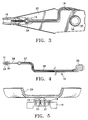
- FIG. 3 shows the slider 15 of a head gimbal assembly 12.
- Head gimbal assembly 12 is composed of a load beam 20, flexure 19, slider 15 and flex circuit 16.
- Slider 15 includes transducer 14 (see Fig. 1) and transducer bonding pad 21 (see Fig. 5) and is connected to flexure 19.
- Flexure 19 is connected to load beam 20 and allows roll and pitch movement of the slider 15.
- Load beam 20 has a mounting ring 23 which is used to connect the head gimbal assembly 12 to arm 11 of actuator 10.
- Load beam 20 and flexure 19 have an alignment hole 24 which is used to align the six head gimbal assemblies 12 with each other with reference to actuator 10.
- Flex circuit 16 is shown being routed from the side of load beam 20 to the center of load beam 20 and then symmetrically along the centerline of load beam 20 and flexure 19 to prevent any biasing of the load beam 20 by flex circuit 16.
- Flex circuit 16 is symmetrically routed around alignment hole 24 to prevent any further biasing of the load beam 20 by flex circuit 16.
- Flex circuit 16 narrows before passing between slider 15 and flexure 19 so as to provide a length of the flex circuit 16 that has low stiffness characteristics. The narrow length of the flex circuit 16 is not bonded to flexure 19 or the load beam 20. Flex circuit 16 is bonded to flexure 19 in the area of alignment hole 24 and to the load beam at various points between alignment hole 24 and mounting ring 23.
- a service loop is formed by the portion of the flex circuit 16 between the point that flex circuit 16 is bonded to flexure 19 in the area of alignment hole 24 and the first point of passage of flex circuit 16 between flexure 19 and slider 15.
- the service loop is therefore located to the rear of the slider 15 and does not have any adverse effects on the flying characteristics if the slider 15.
- FIG. 4 illustrates the flex circuit 16 of the invention.
- Flex circuit 16 has a first area 25 wherein the four conductor are widened and spaced further apart to ease connecting of the four conductors to the bonding pads 18 on wiring terminals 13 on actuator 10.
- the configuration of the four conductor bonding pads in area 25 are designed to mate with the bonding pads 13 configuration of wiring terminals 18 on actuator 10.
- Area 26 of flex circuit 16 is of the length required to extend the four conductors from area 25 to the center line of the load beam 20 of the head gimbal assembly 12 with which the flex circuit 16 is to be used with.
- the size of the conductors may be enlarged in areas 25, 26, 27 and 29 to reduce the line resistance of each of the conductors.
- Area 28 of flex circuit 16 is designed to be symmetrical about the center line of the load beam 20 and/or flexure 19 to minimize any adverse roll and pitch effects the flex circuit 16 may have on the load beam 20 and flexure 16 when bonded to the load beam 20 and/or flexure 16.
- Area 28 of the flex circuit 16 is reduced in width so as to reduce the stiffness of the flex circuit 16 in area 28.
- the stiffness is reduced to minimize the effect of the flex circuit 16 being connected to the slider 15 and to allow the slider 15 to have approximately the same roll and pitch characteristics as the slider 15 would have had if the flex circuit 16 was not attached to the slider 15.
- the stiffness of the area 28 is proportional to the width of area 28 multiplied by the cube of the thickness of area 28 divided by the cube of the length of area 28.
- the thickness of the flex circuit 16 in area 28 has a greater effect on the stiffness than the width of the flex circuit 28.
- the thickness of the flex circuit 16 is bounded by physical restraints to have a minimum thickness range of 1.7 to 2.7 mils. In the manufacture of a flex circuit 16, the thickness of the flex circuit 16 remains constant through all areas of the flex circuit 16. Thus for a given flex circuit 16 the design parameters that can be adjusted are the width and length of the flex circuit 16.
- the bonding of the flex circuit 16 to the load beam and/or flexure advantageously increases the yaw characteristic of the head gimbal assembly thereby allowing a head gimbal assembly using the flex circuit 16 to be used at higher track densities than the same head gimbal assembly using individual wires in a service loop configuration
- Area 29 of flex circuit 16 is enlarged in width and provides that the four conductors be located approximate to the transducer bonding pad 21 on slider 15.
- An opening 30 is provided in flex circuit 16 to allow the physical joining of the slider 15 to the portion of the flexure 19 that allows movement of slider 15. Slider 15, flexure 19 and area 29 of flex circuit 16 will move as a single unit.
- Four conductors 31 are provided at the end of area 28 for bonding to transducer bonding pads 21 on slider 15.
- FIG. 5 illustrates the four conductors 31 of flex circuit 16 being bonded to the four transducer bonding pads 21 on slider 15. Flex circuit 16 is shown as being sandwiched between flexure 19 and slider 15 to form a single movable unit.
Abstract
A head gimbal assembly (12) for use in disk drive systems comprising a load beam (20), a flexure (19) physically connected to the load beam (20), a slider (15) physically connected to the flexure (19) for movement with the flexure (19). The slider (15) includes a transducer (14) and n bonding pads (18) to which the transducer (14) is electrically connected. A flex circuit (16) is provided having n conductors connected to the n bonding pads (18) for providing electrical connection to the transducer (14), a portion of the flex circuit (16) being routed between the flexure (19) and the slider (15) such that the portion, flexure (19) and slider (15) moves as a single unit, and a reduced stiffness area to minimize the effects on roll and pitch characteristics of the slider (15) due to said flex circuit (16) being connected to said n bonding pads (18) on said slider (15) and being routed between the flexure (19) and slider (15).
Description
- This invention relates to magnetic head assemblies used in magnetic disk drive storage systems and in particular to the replacement of the transducer wiring with a flex (flexible) circuit in the head gimbal assembly (HGA) of a head assembly.
- A disk drive typically includes a number of magnetic disks mounted to a common spindle for rotation. Each magnetic disk surface has an associated head arm assembly which includes a head gimbal assembly. The head arm assemblies are generally attached to an actuator for positioning a transducer, which is joined to the head gimbal assemblies, with reference to data tracks on the magnetic disks. In an effort to make disk drives smaller, disk drive manufacturers want the space required for the head gimbal assemblies between adjacent magnetic disk surfaces to be as small as possible.
- A head gimbal assembly is comprised of an air bearing slider on which a magnetic transducer is deposited. The slider is attached to a flexure which in turn is attached to a load beam. Transducer wires are connected to the transducer. The load beam exerts a force on the flexure/slider combination towards the surface of a disk. As the disk is rotated, an air bearing is created between the air bearing surface (ABS) of the slider and the surface of the disk which exerts a force on the head gimbal assembly away from the surface of the disk.
- The transducer can be a inductive type transducer which requires two transducer wires or a magnetoresistive type transducer which requires four or more transducer wires. The transducer preferably is a thin film transducer which is deposited directly onto the slider. Over time the size of the slider has been reduced allowing the data track density on the magnetic disks to be increased thereby resulting in an increased storage capacity for a disk drive system having the same size magnetic disk. The slider size has decreased from a standard size, i.e., 0.160 inch long, 0.125 inch wide, and 0.0345 inch high, to a macro size (70% of standard), then to a nano size (50% of standard) and now to a pico size (25-35% of standard).
- The stiffness of a wire is a function of the diameter, i.e. gauge of the wire and the length of the wire. As the wire length becomes shorter, the stiffness of the wire increases. As the diameter of the wire decreases, the resistivity of the wire increases resulting in a decrease in the signal-to-noise ratio, and the stiffness decreases for a given length of wire. Where a wire is bonded along the wire's length at several locations, the length of the wire defines the stiffness of the wire between two adjacent bonding points.
- In the prior art, a transducer wire is attached to a bonding pad on the slider and to a point on the load beam. The stiffness of the transducer wire places stress on the bond between the bonding wire and the bonding pad, and adversely affects the freedom of movement of the flexure/slider combination and the overall flying characteristics of the slider. In order to reduce these adverse effects of the transducer wires on the head gimbal assembly, the prior art has increased the length of the transducer wires as much as possible to form a loop between the bonding point of the transducer wires on the load beam and the bonding pads on the slider. This loop is referred to as a service loop.
- In a standard size slider, transducer wires used with inductive type transducers were commonly 44 gauge, had a wire diameter of 0.002 inch, and had a service loop length of 0.2 inch which yielded a relative stiffness of 0.5 for the two transducer wires.
- In a nano size slider, the transducer wires used with inductive type transducers were commonly reduced to 48 gauge, a wire diameter of 0.0012 inch, and had a service loop length of 0.15 inch which yielded a relative stiffness of 0.36 for the two transducer wires.
- However when a magnetoresistive type transducer with four transducer wires is used, the four transducer wires are made of 48 gauge, with a wire diameter of 0.0012 inch, and a service loop length of 0.15 inch. This results in the undesirable relative stiffness of 0.73 for the four transducer wires. To reduce the relative stiffness of the four transducer wires, the transducer wire size can be changed to 50 gauge, a wire diameter of 0.001 inch, and if the service loop length remains at 0.15 inch, the relative stiffness will be decreased to 0.36 for the four transducer wires. The increase in the gauge of the transducer wire will have the adverse effects of increasing the resistivity of the wire thereby decreasing the signal-to-noise ratio characteristic of the transducer wire and will decrease production yields because of the increased likelihood of damage to the thinner wires.
- One wiring approach is for the four wires to be routed along the edge of load beam and bonded to the load beam at a bonding point near the slider. The wires then are directed over the top of the flexure to the transducer bonding pads. The size of the service loop is the wire length between the bonding point on the load beam and bonding pads. This routing of the four wires over the top of flexure has the adverse effect of increasing the spacing between adjacent magnetic disk surfaces thereby increasing the overall size of the disk drive.
- Another wiring approach is for the four transducer wires to be routed along the edge of load beam. The transducer wires are divided into two groups wherein the first group of transducer wires is bonded to load beam at a point on one side of the load beam and the second group of transducer wires is bonded to the load beam at a point on the second side of the load beam. Each group of wires then forms a service loop along one side of the slider from the bonding point on the sides of the load beam to the bonding pads. This transducer wire routing has the advantages of decreasing the space between adjacent magnetic disk surfaces and the use of two service loops that aid in maintaining the stability and flying characteristics of the slider. This routing has the disadvantage of restricting how close the head gimbal assembly can come to the spindle because the service loops will be the first point of contact with the spindle thereby deceasing the number of usable tracks on each magnetic disk surface.
- Another wiring approach is for the four wires to be routed along the edge of the load beam and bonded to the load beam at a point along the non-spindle side of the load beam near the slider. A service loop is formed by routing the transducer wires along the non-spindle side of slider from the bonding point on the load beam to bonding pads. This routing of the wires has the advantages of decreasing the space between adjacent magnetic disk surfaces and increases how close the head gimbal assembly can come to the spindle because a service loop will no longer be the first point of contact with the spindle. This routing has the disadvantage that the service loop will bias the slider on one side thereby adversely affecting the flying characteristics of the slider.
- According to this invention, the transducer conductors of a head arm assembly are incorporated into a single flex circuit which is used to route the transducer conductors from the wiring connection points located on the actuator to the bonding points on the slider. The flex circuit is bonded to the load beam at a point to the rear of the slider and is routed between the flexure and the slider to the bonding pads on the forward face of the slider. A service loop is provided by a narrow portion of the flex circuit which is symmetrically located on the center axis of the load beam from the bonding point on the load beam to the point where the flex circuit first enters between the flexure and the slider. The flex circuit makes a transition from the surface of the load beam to the side of the load beam to provide the transducer conductors at the required location on the actuator.
- The advantages of the invention are that it:
- 1. Enables disk drive manufacturers to have tighter disk spacing;
- 2. Enables disk drive manufacturers to pack more data tracks per disk by allowing the slider to fly closer to the spindle hub;
- 3. Eliminates flying height variations induced by the service loop or loops:
- 4. Eliminates any disturbances/noise induced in the service loop due to variation in the flying height of the slider;
- 5. Simplifies head assembly process;
- 6. Facilitates elimination of conformal coating presently placed upon bonding pads after the transducer conductors have been bonded to the bonding pad by reducing the strain upon the bond itself;
- 7. Eliminates need for high bond strength thereby possibly eliminating the need to strip the insulation from the transducer conductors before bonding since successful bonding can be obtained without first stripping the transducer conductors although the resulting bond will still be electrically acceptable but weaker in strength;
- 8. Makes the service loop portion of the flex circuit symmetrical about the head suspension centerline to eliminate roll bias;
- 9. Controls the head gimbal assembly gimbaling pitch and roll stiffness by the flex circuit bonding location and the size of the flex circuit that forms the service loop;
- 10. Allows variations in the conductor size in the flex circuit along the length of the flex circuit to reduce the overall resistance of a conductor in the flex circuit;
- 11. Increases the head gimbal assembly yaw stiffness thereby permitting faster settling time and higher track density;
- 12. Provides wide exposed ends of the conductors which facilitates conductor bonding and increases bond strength; and
- 13. Allows the flex circuit to be designed to meet the physical parameters of the head gimbal assembly so as to provide transducer wiring with consistent effects on the stiffness and flying characteristics of the head gimbal assembly.
- The above and other features and advantages of the present invention will become apparent from the following detailed description of the accompanying drawings, in which:
- FIG. 1 is a side view of six head gimbal assemblies of the invention connected to an actuator;
- FIG. 2 is an exploded plan view showing the connection of two flex circuits bonded to two transducer wiring locations on the actuator;
- FIG. 3 is a plan view of the flex circuit routing along the surface of the load beam of a head gimbal assembly;
- FIG. 4 is a side view of the flex circuit of the invention: and
- Fig. 5 is a front end view illustrating the connection of the flex circuit to the transducer bonding pads of the slider.
- Referring to FIG. 1,
actuator 10 has fourarms 11 to which sixhead gimbal assemblies 12 are attached for common movement byactuator 10.Actuator 10 has sixtransducer wiring terminals 13 where eachwiring terminal 13 receives the four transducer conductors from atransducer 14 on aslider 15 carried by one of the sixhead gimbal assemblies 12.Flex circuits 16 contain the wiring for connectingtransducer 14 towiring terminals 13 onactuator 10. Eachflex circuit 16 is shown as being routed from the slider side of ahead gimbal assembly 12 along a side ofarm 11 to awiring terminal 13 onactuator 10. Theflex circuits 16 on thearm 11 of theactuator 10 having twohead gimbal assemblies 12 are overlapped along the side of actuator arm 1 and then the respective ends of each of theflex circuits 16 fan out to mate with awiring terminal 13 onactuator 10. - FIG. 2 is an exploded view of
portion 2 of FIG. 1 and shows the fanning out of the end of theflex circuits 16 to allow ease in bonding eachconductor 17 of theflex circuits 16 to abonding pad 18 located at awiring terminal 13. - FIG. 3 shows the
slider 15 of ahead gimbal assembly 12.Head gimbal assembly 12 is composed of aload beam 20,flexure 19,slider 15 andflex circuit 16.Slider 15 includes transducer 14 (see Fig. 1) and transducer bonding pad 21 (see Fig. 5) and is connected toflexure 19.Flexure 19 is connected to loadbeam 20 and allows roll and pitch movement of theslider 15.Load beam 20 has a mountingring 23 which is used to connect thehead gimbal assembly 12 toarm 11 ofactuator 10.Load beam 20 andflexure 19 have analignment hole 24 which is used to align the sixhead gimbal assemblies 12 with each other with reference toactuator 10. -
Flex circuit 16 is shown being routed from the side ofload beam 20 to the center ofload beam 20 and then symmetrically along the centerline ofload beam 20 andflexure 19 to prevent any biasing of theload beam 20 byflex circuit 16.Flex circuit 16 is symmetrically routed aroundalignment hole 24 to prevent any further biasing of theload beam 20 byflex circuit 16.Flex circuit 16 narrows before passing betweenslider 15 andflexure 19 so as to provide a length of theflex circuit 16 that has low stiffness characteristics. The narrow length of theflex circuit 16 is not bonded to flexure 19 or theload beam 20.Flex circuit 16 is bonded toflexure 19 in the area ofalignment hole 24 and to the load beam at various points betweenalignment hole 24 and mountingring 23. A service loop is formed by the portion of theflex circuit 16 between the point thatflex circuit 16 is bonded toflexure 19 in the area ofalignment hole 24 and the first point of passage offlex circuit 16 betweenflexure 19 andslider 15. The service loop is therefore located to the rear of theslider 15 and does not have any adverse effects on the flying characteristics if theslider 15. - FIG. 4 illustrates the
flex circuit 16 of the invention.Flex circuit 16 has afirst area 25 wherein the four conductor are widened and spaced further apart to ease connecting of the four conductors to thebonding pads 18 onwiring terminals 13 onactuator 10. The configuration of the four conductor bonding pads inarea 25 are designed to mate with thebonding pads 13 configuration ofwiring terminals 18 onactuator 10.Area 26 offlex circuit 16 is of the length required to extend the four conductors fromarea 25 to the center line of theload beam 20 of thehead gimbal assembly 12 with which theflex circuit 16 is to be used with. The size of the conductors may be enlarged inareas Area 28 offlex circuit 16 is designed to be symmetrical about the center line of theload beam 20 and/orflexure 19 to minimize any adverse roll and pitch effects theflex circuit 16 may have on theload beam 20 andflexure 16 when bonded to theload beam 20 and/orflexure 16. -
Area 28 of theflex circuit 16 is reduced in width so as to reduce the stiffness of theflex circuit 16 inarea 28. The stiffness is reduced to minimize the effect of theflex circuit 16 being connected to theslider 15 and to allow theslider 15 to have approximately the same roll and pitch characteristics as theslider 15 would have had if theflex circuit 16 was not attached to theslider 15. - The stiffness of the
area 28 is proportional to the width ofarea 28 multiplied by the cube of the thickness ofarea 28 divided by the cube of the length ofarea 28. The thickness of theflex circuit 16 inarea 28 has a greater effect on the stiffness than the width of theflex circuit 28. The thickness of theflex circuit 16 is bounded by physical restraints to have a minimum thickness range of 1.7 to 2.7 mils. In the manufacture of aflex circuit 16, the thickness of theflex circuit 16 remains constant through all areas of theflex circuit 16. Thus for a givenflex circuit 16 the design parameters that can be adjusted are the width and length of theflex circuit 16. It has been found that with a flex thickness of 2.7 mils and thearea 28 having an approximate length of 0.170 mils and a width of 16 mils, that the roll head gimbal assembly stiffness using theflex circuit 16 of four conductor will be 0.69 gr/degree. The prior art head gimbal assembly using services loops of four wires has a stiffness of 0.8 gr/degree. The use of aflex circuit 16 allows a greater degree of freedom of movement of the slider than the prior art use of individual wires within a series loop. It has further been found the bonding of theflex circuit 16 to the load beam and/or flexure advantageously increases the yaw characteristic of the head gimbal assembly thereby allowing a head gimbal assembly using theflex circuit 16 to be used at higher track densities than the same head gimbal assembly using individual wires in a service loop configuration -
Area 29 offlex circuit 16 is enlarged in width and provides that the four conductors be located approximate to thetransducer bonding pad 21 onslider 15. Anopening 30 is provided inflex circuit 16 to allow the physical joining of theslider 15 to the portion of theflexure 19 that allows movement ofslider 15.Slider 15,flexure 19 andarea 29 offlex circuit 16 will move as a single unit. Fourconductors 31 are provided at the end ofarea 28 for bonding totransducer bonding pads 21 onslider 15. - FIG. 5 illustrates the four
conductors 31 offlex circuit 16 being bonded to the fourtransducer bonding pads 21 onslider 15.Flex circuit 16 is shown as being sandwiched betweenflexure 19 andslider 15 to form a single movable unit. - While the embodiments of the present invention are described above, it is contemplated that modifications may be made thereto for particular applications without departing from the spirit and scope of the present invention. Accordingly, it is intended that the embodiments described be considered only as illustrative of the present invention and that the scope thereof should not be limited thereto but be determined by reference to the claims hereinafter provided.
Claims (18)
- A head gimbal assembly (12) for coaction with an actuator arm used in disk drive systems comprising:a load beam (20);a flexure (19) physically connected to said load beam (20) for allowing movement of said flexure (19);an air bearing slider (15) physically connected to said flexure (19) for movement with said flexure (19), said slider (15) having a rear end disposed towards said load beam, said slider including a transducer (14) and a number n of bonding pads (18) to which said transducer (14) is electrically connected, said actuator arm having a number of wiring terminals;at least one flex circuit (16) having a number of conductors connected to said n bonding pads (18) for connecting said bonding pads to said wiring terminals of said actuator arm, a portion of said flex circuit (16) being routed between said flexure (19) and said rear end of said slider (15) to form a service loop therebetween towards the front part of said flexure (19), wherein said service loop, said flexure (19) and said slider (15) move as a single unit; anda reduced stiffness area of said flex circuit (16) formed by said service loop being narrowed relative to other areas of said flex circuit (16) for minimizing the effects on roll and pitch of said slider (15).
- The head gimbal assembly (12) of Claim 1, wherein said reduced stiffness area of said flex circuit (16) is located symmetrically about the center line of said load beam (20) and is connected to said load beam (20).
- The head gimbal assembly (12) of Claims 1 or 2, wherein said flex circuit (16) is routed along the center of said flexure (19) and then along the side of said load beam.
- The head gimbal assembly (12) of any one of Claims 1 to 3, wherein said flex circuit (16) has an area (25) in which said ends of said conductors are enlarged for ease in connecting to said bonding pads.
- The head gimbal assembly (12) of any one of Claims 1 to 4, wherein said slider (15) has opposing first and second sides and said bonding pads (18) are located on said first side of said slider (15); andsaid flex circuit (16) having a narrow area first and second ends wherein said first end is located adjacent to said second side of said slider (15).
- The head gimbal assembly (12) of any one of Claim 1-5, wherein said flex circuit (16) is bonded to said load beam (20) at a point on said flex circuit (16) adjacent to said second end of said narrow area of said flex circuit (16).
- A flex circuit (16) for use in a head gimbal assembly (12) used in disk drive systems, said head gimbal assembly (12) including a load beam (20), a flexure (19) physically connected to said load beam (20) for allowing movement of said flexure (19) and a slider (15) physically connected to said flexure (19) for movement with said flexure (19) where said slider (15) includes a transducer (14) and bonding pads (18) to which said transducer (14) is electrically connected, said flex circuit (16) comprising:conductors connected to said bonding pads (18) for providing electrical connection to said transducer (14);a portion of said flex circuit (16) being routed between said flexure (19) and said slider (15) such that said portion, said flexure (19) and said slider (15) moves as a single unit; anda reduced stiffness area to minimize the effects on roll and pitch characteristics of said slider (15).
- The flex circuit (16) of Claim 7 wherein said reduced stiffness area of said flex circuit (16) is located in said flex circuit (16) such that said reduced stiffness area will be symmetrically located about the centerline of said load beam (20) when said flex circuit (16) is connected to said load beam.
- The flex circuit (16) of Claims 7 or 8 wherein said flex circuit (16) is routed and connected to the side of said load beam for providing said m conductors in an orientation for connecting to said n bonding pads.
- The flex circuit (16) of any one of Claims 7 to 9 further comprising:an area (25) in which said ends of said m conductors are enlarged for connecting to said n bonding pads.
- The flex circuit (16) of any one of Claims 7 to 10, where said slider (15) has opposing first and second sides and said bonding pads (18) are located on said first side of said slider (15), wherein:
said portion of said flex circuit (16) has first and second ends and said first end is located adjacent to said second side of said slider (15). - The flex circuit (16) of Claim 11, wherein said flex circuit (16) is bonded to said load beam (20) at a point on said flex circuit (16) adjacent to said second end of said portion of said flex circuit (16).
- An apparatus comprising:an actuator (10) having an actuator arm (11) and two transducer wiring terminals (13) where each wiring terminal has n terminal connecting points;two head gimbal assemblies (12) oppositely mounted on said actuator arm (11) where each head gimbal assembly (12) includes:a transducer (14) having n transducer (14) connecting points;a flex circuit (16) having n conductors for electrically connecting the n transducer (14) connecting points to said n terminal connecting points of one of said two transducer wiring terminals (13) where said flex circuit (16) makes a transition from a first orientation on said head gimbal assembly (12) to a connection orientation to match the orientation of said n terminal connecting points on one of said two transducer wiring terminals (13) on said actuator (10), and after said flex circuit (16) makes said transition to said connection orientation, said flex circuit (16) is routed along a side of said actuator arm (11);where each of said flex circuits (16) on said two flex circuits (16) are overlapping and routed along the same said side of said actuator arm (11) to the location of said two transducer wiring terminals (13) on said actuator (10) and said flex circuits (16) diverge and are routed to one of said two transducer wiring terminals (13) on said actuator (10).
- The apparatus of Claim 13 wherein each of said head gimbal assemblies (12) comprises:a load beam (20);a flexure (19) physically connected to said load beam (20);a slider (15) physically connected to said flexure (19) for movement with said flexure (19), said slider (15) including a transducer (14) and n bonding pads (18) to which said transducer (14) is electrically connected; anda flex circuit (16) having n conductors connected to said n bonding pads (18) for providing electrical connection to said transducer (14), a portion of said flex circuit (16) being routed between said flexure (19) and said slider (15) such that said portion, said flexure (19) and said slider (15) moves as a single unit, and a reduced stiffness area to minimize the effects on roll and pitch characteristics of said slider (15) due to said flex circuit (16) being connected to said n bonding pads (18) on said slider (15).
- The apparatus of Claim 13 or 14, wherein said reduced stiffness area of said flex circuit (16) is located symmetrically about the centerline of said load beam (20) and is connected to said load beam (20).
- The apparatus of any one of Claims 13 to 15, wherein said flex circuit (16) has an area in which said ends of said n conductors are enlarged for connecting to said n terminal connecting points of one of said two transducer wiring terminals (13) on said actuator (10).
- The apparatus of any one of Claims 13 to 16, wherein:
said slider (15) has opposing first and second sides and said n bonding pads (18) are located on said first side of said slider (15); and
said narrow area of said flex circuit (16) has first and second ends and said first end is located adjacent to said second side of said slider (15). - The apparatus of Claim 17, wherein said flex circuit (16) is bonded to said load beam at a point on said flex circuit (16) or on said load beam (20) adjacent to said second end of said narrow area of said flex circuit (16).
Applications Claiming Priority (2)
| Application Number | Priority Date | Filing Date | Title |
|---|---|---|---|
| US53351895A | 1995-09-25 | 1995-09-25 | |
| US533518 | 1995-09-25 |
Publications (1)
| Publication Number | Publication Date |
|---|---|
| EP0764942A1 true EP0764942A1 (en) | 1997-03-26 |
Family
ID=24126306
Family Applications (1)
| Application Number | Title | Priority Date | Filing Date |
|---|---|---|---|
| EP96115327A Withdrawn EP0764942A1 (en) | 1995-09-25 | 1996-09-24 | Flexible circuit for magnetic head assembly having reduced stiffness area for minimizing the effects of roll and pitch |
Country Status (3)
| Country | Link |
|---|---|
| US (1) | US5859749A (en) |
| EP (1) | EP0764942A1 (en) |
| JP (1) | JPH09167454A (en) |
Cited By (6)
| Publication number | Priority date | Publication date | Assignee | Title |
|---|---|---|---|---|
| US5883758A (en) * | 1996-08-07 | 1999-03-16 | Hutchinson Technology Incorporated | Lead structure with stainless steel base for attachment to a suspension |
| US5982584A (en) * | 1996-12-19 | 1999-11-09 | Hutchinson Technology Incorporated | Integrated lead suspension flexure with serially arranged metal-backed and suspended insulator portions for hygrothermal compensation |
| US6147839A (en) * | 1996-12-23 | 2000-11-14 | Hutchinson Technology, Inc. | Head suspension with outriggers extending across a spring region |
| US6381100B1 (en) | 1996-12-19 | 2002-04-30 | Hutchinson Technology Incorporated | Integrated lead suspension flexure with balanced parallel leads for insulator layer hygrothermal compensation |
| US6612016B1 (en) | 1997-12-18 | 2003-09-02 | Hutchinson Technology Incorporated | Method of making integrated lead suspension flexure with balanced parallel leads for insulator layer hygrothermal compensation |
| US6765763B2 (en) | 2000-06-16 | 2004-07-20 | Seagate Technology Llc | Actuator system for disc drive |
Families Citing this family (18)
| Publication number | Priority date | Publication date | Assignee | Title |
|---|---|---|---|---|
| KR950020658A (en) * | 1993-12-07 | 1995-07-24 | 새끼자와 다다시 | Magnetic disk device |
| JPH08203030A (en) * | 1995-01-25 | 1996-08-09 | Sony Corp | Magnetic head device and method for manufacturing the same |
| JPH11195214A (en) * | 1997-12-26 | 1999-07-21 | Tdk Corp | Manufacture of magnetic head device |
| US6202288B1 (en) | 1997-12-26 | 2001-03-20 | Tdk Corporation | Method for manufacturing magnetic head suspension assembly with head IC chip |
| US6399889B1 (en) | 1998-09-14 | 2002-06-04 | Seagate Technology Llc | Head interconnect circuit with alignment finger |
| US6266869B1 (en) | 1999-02-17 | 2001-07-31 | Applied Kinetics, Inc. | Method for assembling components |
| US7191512B2 (en) * | 1998-09-29 | 2007-03-20 | Applied Kinetics, Inc. | Tray system for holding and positioning components |
| US7127799B2 (en) * | 1998-10-02 | 2006-10-31 | Applied Kinetics, Inc. | Head gimbal assembly method |
| WO2000030081A1 (en) * | 1998-11-13 | 2000-05-25 | Tdk Corporation | Record/reproduce head support mechanism and record/reproduce apparatus |
| US6154343A (en) * | 1998-12-18 | 2000-11-28 | Magnecomp Corp. | Suspension manufacturing method and product |
| US6278585B1 (en) | 1999-04-19 | 2001-08-21 | International Business Machines Corporation | Transducer suspension termination system |
| US6636383B1 (en) * | 2000-03-17 | 2003-10-21 | Maxtor Corporation | Disk drive actuator arm assembly with unitary flex cable |
| JP2001266511A (en) * | 2000-03-24 | 2001-09-28 | Toshiba Corp | Head suspension assembly and magnetic disk unit provided with head suspension assembly |
| US6522504B1 (en) * | 2001-01-31 | 2003-02-18 | Western Digital Technologies, Inc. | Head stack assembly and disk drive using a reversed direction head gimbal assembly |
| US7027141B2 (en) * | 2001-05-03 | 2006-04-11 | Applied Kinetics, Inc. | Static attitude determination and adjust of head suspension components |
| KR100438777B1 (en) * | 2001-11-06 | 2004-07-05 | 삼성전자주식회사 | Hard disk drive comprising flexible printed circuit with hole |
| US7593194B2 (en) * | 2004-11-30 | 2009-09-22 | International Business Machines Corporation | Tape recording head promoting lateral motion |
| WO2009003318A1 (en) * | 2007-07-05 | 2009-01-08 | Sae Magnetics (H.K.) Ltd. | Suspension design for high shock performance soldering ball bonding |
Citations (5)
| Publication number | Priority date | Publication date | Assignee | Title |
|---|---|---|---|---|
| JPS62217476A (en) * | 1985-10-28 | 1987-09-24 | Hitachi Ltd | Magnetic head assembly |
| EP0434261A1 (en) * | 1989-12-22 | 1991-06-26 | Seagate Technology International | Apparatus for supporting a conductor sleeve in a head gimbal assembly |
| WO1993017416A1 (en) * | 1992-02-27 | 1993-09-02 | Hutchinson Technology Incorporated | Gimbal for magnetic head suspension systems |
| WO1994016438A1 (en) * | 1993-01-07 | 1994-07-21 | Hutchinson Technology Incorporated | Improved transducer gimbal structure |
| JPH0831127A (en) * | 1994-07-07 | 1996-02-02 | Nec Corp | Magnetic head device |
Family Cites Families (7)
| Publication number | Priority date | Publication date | Assignee | Title |
|---|---|---|---|---|
| US4379316A (en) * | 1981-06-11 | 1983-04-05 | Siemens Corporation | Read/write head carriage assembly for a floppy disk drive |
| JPS6119083A (en) * | 1984-07-05 | 1986-01-27 | キヤノン電子株式会社 | Conductive member |
| US4811143A (en) * | 1986-03-31 | 1989-03-07 | Kabushiki Kaisha Toshiba | Head supporting mechanism for maintaining close operative relationship between magnetic heads and a flexible disk |
| US4819094A (en) * | 1986-08-12 | 1989-04-04 | Oberg Gary R | Damped magnetic head suspension assembly |
| US5185683A (en) * | 1987-12-21 | 1993-02-09 | Hutchinson Technology, Inc. | Suspension arm mounting assembly |
| JP2616631B2 (en) * | 1992-04-23 | 1997-06-04 | 日本電気株式会社 | Magnetic head |
| JP2935802B2 (en) * | 1993-12-09 | 1999-08-16 | アルプス電気株式会社 | Levitated magnetic head device |
-
1996
- 1996-09-24 EP EP96115327A patent/EP0764942A1/en not_active Withdrawn
- 1996-09-25 JP JP8252846A patent/JPH09167454A/en active Pending
-
1997
- 1997-04-14 US US08/840,260 patent/US5859749A/en not_active Expired - Lifetime
Patent Citations (5)
| Publication number | Priority date | Publication date | Assignee | Title |
|---|---|---|---|---|
| JPS62217476A (en) * | 1985-10-28 | 1987-09-24 | Hitachi Ltd | Magnetic head assembly |
| EP0434261A1 (en) * | 1989-12-22 | 1991-06-26 | Seagate Technology International | Apparatus for supporting a conductor sleeve in a head gimbal assembly |
| WO1993017416A1 (en) * | 1992-02-27 | 1993-09-02 | Hutchinson Technology Incorporated | Gimbal for magnetic head suspension systems |
| WO1994016438A1 (en) * | 1993-01-07 | 1994-07-21 | Hutchinson Technology Incorporated | Improved transducer gimbal structure |
| JPH0831127A (en) * | 1994-07-07 | 1996-02-02 | Nec Corp | Magnetic head device |
Non-Patent Citations (2)
| Title |
|---|
| PATENT ABSTRACTS OF JAPAN vol. 12, no. 79 (P - 676) 12 March 1988 (1988-03-12) * |
| PATENT ABSTRACTS OF JAPAN vol. 96, no. 9 28 June 1996 (1996-06-28) * |
Cited By (7)
| Publication number | Priority date | Publication date | Assignee | Title |
|---|---|---|---|---|
| US5883758A (en) * | 1996-08-07 | 1999-03-16 | Hutchinson Technology Incorporated | Lead structure with stainless steel base for attachment to a suspension |
| US5982584A (en) * | 1996-12-19 | 1999-11-09 | Hutchinson Technology Incorporated | Integrated lead suspension flexure with serially arranged metal-backed and suspended insulator portions for hygrothermal compensation |
| US6381100B1 (en) | 1996-12-19 | 2002-04-30 | Hutchinson Technology Incorporated | Integrated lead suspension flexure with balanced parallel leads for insulator layer hygrothermal compensation |
| US6147839A (en) * | 1996-12-23 | 2000-11-14 | Hutchinson Technology, Inc. | Head suspension with outriggers extending across a spring region |
| US6612016B1 (en) | 1997-12-18 | 2003-09-02 | Hutchinson Technology Incorporated | Method of making integrated lead suspension flexure with balanced parallel leads for insulator layer hygrothermal compensation |
| US6765763B2 (en) | 2000-06-16 | 2004-07-20 | Seagate Technology Llc | Actuator system for disc drive |
| SG165146A1 (en) * | 2000-06-16 | 2010-10-28 | Seagate Technology Llc | Actuator system for disc drive |
Also Published As
| Publication number | Publication date |
|---|---|
| JPH09167454A (en) | 1997-06-24 |
| US5859749A (en) | 1999-01-12 |
Similar Documents
| Publication | Publication Date | Title |
|---|---|---|
| US5859749A (en) | Flexible circuit for magnetic head assembly | |
| US5956209A (en) | Integrated suspension flexure having a compliant tip termination platform | |
| EP1174860B1 (en) | Magnetic head supporting mechanism | |
| US6275358B1 (en) | Conductor trace array having passive stub conductors | |
| US5986853A (en) | Transducer suspension system | |
| US5737152A (en) | Suspension with multi-layered integrated conductor trace array for optimized electrical parameters | |
| US5995328A (en) | Multi-layered integrated conductor trace array interconnect structure having optimized electrical parameters | |
| US6125014A (en) | Via-less connection using interconnect traces between bond pads and a transducer coil of a magnetic head slider | |
| US7006330B1 (en) | Head stack assembly including a ground conductive pad for grounding a slider to a gimbal | |
| US20080253025A1 (en) | Method and apparatus for providing an additional ground pad and electric al connection for grounding a magnetic recording head | |
| US7110222B2 (en) | System and apparatus for assembling hard disk drive integrated lead suspensions to arm electronics cables via additional degrees of freedom at the tail termination and impedance grooming thereof | |
| JPH10507028A (en) | Integrated head / electronic circuit interconnect suspension for data recording disk drive | |
| JPH06168414A (en) | Combination system of thin-film magnetic-head converter and suspension part as well as its manufacture | |
| US7113372B2 (en) | HGA plateau gimbal design | |
| US3323116A (en) | Electromagnetic transducer and method of fabrication | |
| US5835306A (en) | Integrated gimbal suspension assembly with assymetric bond pad | |
| JP2001501762A (en) | Flex circuit flexure with integrated high compliance gimbal | |
| US6219202B1 (en) | Slider suspension assembly and method for attaching a slider to a suspension in a data-recording disk file including a flexible integrated cable having an aperture therein for permitting electrical contact | |
| US6351348B1 (en) | Minimal stiffness conductors for a head gimbal assembly | |
| US6747849B1 (en) | High performance suspension with reduced flow-induced vibration | |
| CA2221966A1 (en) | Suspension with integrated conductor having controlled capacitance | |
| US20030128474A1 (en) | Low electrical impedance slider grounding | |
| US5771138A (en) | Head gimbal assembly with transducer wires attached at two points to slider | |
| KR20020072247A (en) | Magnetic transducer with integrated charge bleed resistor | |
| JPH0954930A (en) | Magnetic head supporting mechanism |
Legal Events
| Date | Code | Title | Description |
|---|---|---|---|
| PUAI | Public reference made under article 153(3) epc to a published international application that has entered the european phase |
Free format text: ORIGINAL CODE: 0009012 |
|
| AK | Designated contracting states |
Kind code of ref document: A1 Designated state(s): DE NL |
|
| 17P | Request for examination filed |
Effective date: 19970716 |
|
| 17Q | First examination report despatched |
Effective date: 20000426 |
|
| STAA | Information on the status of an ep patent application or granted ep patent |
Free format text: STATUS: THE APPLICATION IS DEEMED TO BE WITHDRAWN |
|
| 18D | Application deemed to be withdrawn |
Effective date: 20000907 |