EP0765093A2 - Method for detecting overload situations in subscriber connection modules of a communication system - Google Patents
Method for detecting overload situations in subscriber connection modules of a communication system Download PDFInfo
- Publication number
- EP0765093A2 EP0765093A2 EP96113852A EP96113852A EP0765093A2 EP 0765093 A2 EP0765093 A2 EP 0765093A2 EP 96113852 A EP96113852 A EP 96113852A EP 96113852 A EP96113852 A EP 96113852A EP 0765093 A2 EP0765093 A2 EP 0765093A2
- Authority
- EP
- European Patent Office
- Prior art keywords
- overload
- utilization
- communication
- measured
- gzs
- Prior art date
- Legal status (The legal status is an assumption and is not a legal conclusion. Google has not performed a legal analysis and makes no representation as to the accuracy of the status listed.)
- Granted
Links
- 238000004891 communication Methods 0.000 title claims abstract description 73
- 238000000034 method Methods 0.000 title claims abstract description 51
- 230000011664 signaling Effects 0.000 claims abstract description 45
- 230000005540 biological transmission Effects 0.000 claims description 15
- 238000012545 processing Methods 0.000 claims description 11
- 238000003860 storage Methods 0.000 claims description 7
- 238000001514 detection method Methods 0.000 claims description 5
- 230000006870 function Effects 0.000 claims 1
- 101150010006 slmo gene Proteins 0.000 abstract description 13
- 238000012546 transfer Methods 0.000 abstract description 2
- 238000010408 sweeping Methods 0.000 abstract 1
- 238000005259 measurement Methods 0.000 description 6
- LPLLVINFLBSFRP-UHFFFAOYSA-N 2-methylamino-1-phenylpropan-1-one Chemical compound CNC(C)C(=O)C1=CC=CC=C1 LPLLVINFLBSFRP-UHFFFAOYSA-N 0.000 description 3
- 241000132539 Cosmos Species 0.000 description 3
- 235000005956 Cosmos caudatus Nutrition 0.000 description 3
- 230000015572 biosynthetic process Effects 0.000 description 3
- 238000010586 diagram Methods 0.000 description 2
- 238000007781 pre-processing Methods 0.000 description 2
- 238000013461 design Methods 0.000 description 1
- 230000000977 initiatory effect Effects 0.000 description 1
- 238000012432 intermediate storage Methods 0.000 description 1
- 238000012544 monitoring process Methods 0.000 description 1
- 238000012360 testing method Methods 0.000 description 1
- 230000001960 triggered effect Effects 0.000 description 1
- 230000000007 visual effect Effects 0.000 description 1
Images

Classifications
-
- H—ELECTRICITY
- H04—ELECTRIC COMMUNICATION TECHNIQUE
- H04Q—SELECTING
- H04Q11/00—Selecting arrangements for multiplex systems
- H04Q11/04—Selecting arrangements for multiplex systems for time-division multiplexing
- H04Q11/0428—Integrated services digital network, i.e. systems for transmission of different types of digitised signals, e.g. speech, data, telecentral, television signals
-
- H—ELECTRICITY
- H04—ELECTRIC COMMUNICATION TECHNIQUE
- H04Q—SELECTING
- H04Q2213/00—Indexing scheme relating to selecting arrangements in general and for multiplex systems
- H04Q2213/13096—Digital apparatus individually associated with a subscriber line, digital line circuits
-
- H—ELECTRICITY
- H04—ELECTRIC COMMUNICATION TECHNIQUE
- H04Q—SELECTING
- H04Q2213/00—Indexing scheme relating to selecting arrangements in general and for multiplex systems
- H04Q2213/13103—Memory
-
- H—ELECTRICITY
- H04—ELECTRIC COMMUNICATION TECHNIQUE
- H04Q—SELECTING
- H04Q2213/00—Indexing scheme relating to selecting arrangements in general and for multiplex systems
- H04Q2213/13106—Microprocessor, CPU
-
- H—ELECTRICITY
- H04—ELECTRIC COMMUNICATION TECHNIQUE
- H04Q—SELECTING
- H04Q2213/00—Indexing scheme relating to selecting arrangements in general and for multiplex systems
- H04Q2213/13164—Traffic (registration, measurement,...)
-
- H—ELECTRICITY
- H04—ELECTRIC COMMUNICATION TECHNIQUE
- H04Q—SELECTING
- H04Q2213/00—Indexing scheme relating to selecting arrangements in general and for multiplex systems
- H04Q2213/13166—Fault prevention
-
- H—ELECTRICITY
- H04—ELECTRIC COMMUNICATION TECHNIQUE
- H04Q—SELECTING
- H04Q2213/00—Indexing scheme relating to selecting arrangements in general and for multiplex systems
- H04Q2213/13176—Common channel signaling, CCS7
-
- H—ELECTRICITY
- H04—ELECTRIC COMMUNICATION TECHNIQUE
- H04Q—SELECTING
- H04Q2213/00—Indexing scheme relating to selecting arrangements in general and for multiplex systems
- H04Q2213/13204—Protocols
-
- H—ELECTRICITY
- H04—ELECTRIC COMMUNICATION TECHNIQUE
- H04Q—SELECTING
- H04Q2213/00—Indexing scheme relating to selecting arrangements in general and for multiplex systems
- H04Q2213/1332—Logic circuits
Definitions
- Program-controlled communication systems have a central controller and subscriber connection modules connected to it, by means of which communication connections are implemented for connecting communication terminals.
- a subscriber line module provides 24 communication lines to which at least 24 communication terminals can be connected.
- a signaling channel - known in the art as a D channel - with, for example, a standardized transmission capacity of 16 kbit / s is routed via each of these communication connections. Signaling messages are transmitted both to the communication terminal and to the communication system via the signaling channel.
- a considerably higher flow of signaling messages from the communication system to the communication terminals occurs. This can lead to an excessive flow of signaling messages to the communication terminal, and thus to an overload of the subscriber line modules, in particular for certain uses of the communication terminal.
- the subscriber line modules each have a microprocessor system, with the aid of which the processing requests transmitted by the processes implemented in the subscriber line modules are processed.
- the processes are organized as independent tasks, which have different priority levels with regard to message processing.
- the resource processing capacity of the Microprocessor system is provided within a subscriber line module for message processing in interprocess communication and for resource management of the other resources on the subscriber line module. An overload of the microprocessor system is caused both by a considerable flood of messages in the direction of communication terminals and by the messages to be transmitted to the central control.
- a known method of determining the overload of a subscriber line module is to use the number of free memory elements of a memory element pool managed by the operating system.
- the storage elements are temporarily assigned to the respective processes or tasks for intermediate storage before information, i.e. the respective process can save its data or information on the memory elements assigned to it.
- the object on which the invention is based is to design a method for detecting an overload of a subscriber line module in such a way that a general fault condition or failure of the subscriber line module is avoided after detection by targeted countermeasures.
- the object is achieved by the features of patent claim 1.
- the essential aspect of the method according to the invention is to be seen in that, in order to detect an overload, the load on the microprocessor system, the signaling channels directed to the communication terminals and the memory element pool is measured continuously, and the overload of the subscriber line module is detected by comparing the measured loads with predetermined load limits.
- targeted or general, fast-acting countermeasures can be initiated.
- One of these countermeasures can be seen, for example, in the fact that the formation and transmission of signaling messages, which significantly influence the processor processing resources, is restricted to the communication devices causing a flood of signaling messages.
- those communication terminals to which the greatest number of signaling messages are currently being transmitted and a corresponding countermeasure, namely no longer to transmit all signaling messages, can be specifically determined.
- individual or all communication connections can be taken out of operation in order to avoid a currently pending overload of the respective subscriber line module - claims 16 and 17.
- overload levels are advantageously identified by comparing the measured workloads with different, predetermined load limits - claim 2.
- This overload strategy is useful in a multi-level countermeasure strategy, the individual countermeasures representing part or parts of an overall strategy.
- the subscriber line module is overloaded detected when the measured workloads are exceeded above the specified workload limits. Consequently, falling below the predetermined utilization limits constitutes a normal load - claim 3. In order to suppress extremely short-term overloads and incorrect measurements, exceeding or falling below utilization limits is only determined if these are measured within a predetermined time interval - claim 4.
- the utilization of the microprocessor system is advantageously determined by the number of idle tasks processed within a predetermined time interval. If the measured number falls below a predetermined number of idle tasks representing the load limit, an overload of the microprocessor system is detected - claim 5. The number of idle tasks is advantageously detected by a counter - claim 6.
- the utilization of the signaling channel is measured particularly advantageously by determining an overall message length.
- the message lengths of the individual signaling messages are recorded for each signaling channel and summed to form a total message length. If this total message length exceeds a limit message length representing the utilization limit within a time interval, the overload is recognized by the signaling to the communication terminals.
- a first overload state of a subscriber line module is determined when the load limits are constantly exceeded within a overload interval.
- a message indicating the first overload condition is formed - claim 8. This additional measure avoids the initiation of countermeasures in the event of a short-term violation individual utilization limits and when they are identified, targeted countermeasures can be initiated.
- the overload of the memory element pool is advantageously determined by measuring the memory elements that are still free.
- the measured free memory elements are compared with a predetermined number representing the utilization limit, and if the number falls below the predetermined number, an overload of the memory element pool is determined - claim 9.
- the utilization of the memory element pool is advantageously measured after each transmission of a signaling message to a connected communication terminal - claim 10 This point in time is advantageous because if the utilization limit is exceeded, further transmission of messages can be avoided.
- Communication terminals KE can be connected to the communication system KS or the subscriber line module SLMO.
- the communication terminals KE are operated in the stimulus method (S) - all settings of the communication terminal KE are made from the communication system KS - or according to a protocol method (P) - after transmitting a signaling message si, the communication terminal KE independently carries out the settings.
- the signaling messages si are transmitted via a signaling channel D, each via a communication connection KA, together with the useful information ni, for example digitized voice information.
- the subscriber line module SLMO is connected to a control device CCU that coordinates and controls the communication system KS. 1 further shows the program structure of the subscriber line module SLMO shown as an example, a similar program structure being implemented in the other subscriber line modules SLMO (not shown).
- the program structure is structured in various processes explained below. The processes are organized as independent tasks, which have different priority levels with regard to message processing - messages from the central control device CCU or from the communication terminals KE or to these.
- HDLC TASK Communication between the central control device CCU and the subscriber line module SLMO is implemented in this by the two HDLC transmission routines HDLC TASK, HDLC INT.
- Both HDLC transmission routines HDLC TASK, HDLC INT contain driver routines for message traffic, the first HDLC transmission routine HDLC TASK for sending messages m to the central control unit CCU and the second HDLC transmission routine HDLC INT for receiving Messages m from the central control unit CCU is responsible.
- the requirements of the HDLC transmission routines HDLC TASK, HDLC INT are processed with the highest priority.
- the two HDLC transmission routines HDLC TASK, HDLC INT communicate with an apron device handler VDH, in which a processing preprocessing (call processing) of the signaling information si transmitted by the communication terminals KE is carried out.
- a processing preprocessing call processing
- the apron device handler VDH is a process realized by a program module IWU-S for the preprocessing of switching procedures of a stimulus communication terminal KE (S) and further a process realized by a program IWU-S0 for processing the switching messages a "protocol" communication terminal KE (P) - for example an ISDN communication terminal with an S0 interface - is provided.
- a layer 3 program L3P which communicates in particular with the program IWU-S via a defined interface IS, is included in particular for the formation of special messages for the display devices of stimulus communication terminals KE (S).
- the layer 3 program L3P is preferably provided for the formation and handling of display messages for all stimulus communication terminals KE (S) connected to the respective subscriber line module SLMO, the information content of these display messages being visual in the respective stimulus communication terminals KE in a display device is shown.
- layer 2 is implemented according to the OSI reference model for user network signaling and information transfer both in the direction of the central control device CCU and in the direction of the communication terminals KE. This layer 2 takes over for the layer 3, ie the network layer, the secure transmission of the signaling information si in both directions.
- the layer 2 program L2P communicates with a layer 1 program L1P, which represents the link to the circuitry transmission and power supply devices for the respectively connected communication terminals KE.
- This layer 1 program L1P activates and deactivates the communication connections KA, controls test loops and performs power management.
- An operating system COSMOS is implemented for the administration and operation of the microprocessor system resources.
- This operating system COSMOS also manages the memory elements SE of a memory element pool SEP and temporarily allocates them to the respective processes or program modules, as required - in particular for message processing - the memory element pool SEP with its memory elements SE is indicated by a dashed rectangle in the operating system block.
- a counter Z is provided in the operating system COSMOS, with the aid of which the still free memory elements SE of the memory element pool SEP are counted.
- a safety and operating technology program module STB For operational control, i.e. The operational settings of the SLMO subscriber connection module are provided by a safety and operating technology program module STB.
- This operating technology program module STB also provides all operating parameters with regard to the load limits required for overload detection. These are, in particular, operating parameters via a microprocessor system utilization limit GZS, the total limit message length gznl, and the interval times IV and a memory element pool utilization limit GZ.
- the message lengths L of the signaling messages si to be transmitted in each case in the direction of the communication terminal KE are ascertained in the layer 2 program L2P and transmitted to an overload routine URL.
- the overload routine URL has a memory element pool measuring routine SEP-MR, a signaling channel measuring routine D-MR, an overload program UP and a communication port-related signaling channel measuring routine KAD-MR.
- the overload status is communicated in particular to the process implemented by the program IWU-S for the control of stimulus communication terminals KE (S) by level 1 and level 2 overload messages by 1.2.
- the overload messages By transmitting the overload messages by 1.2, the transmission of display messages to individual, particularly overloaded communication connections KA or to all or the transmission of all signaling messages si to individual or particularly overloaded communication connections KA is prevented.
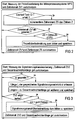
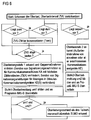
- FIGS. 2 to 6 The methods implemented in the measurement routines D-MR, SEP-MR and in the overload program UP are shown in FIGS. 2 to 6.
- the respective flowcharts are essentially self-explanatory and in particular show the method steps leading to the detection of an overload with regard to measuring the process load of the microprocessor MPS, measuring the signaling channel load, measuring the load of the memory element pool SEP, measuring the communication port-specific signaling channel load and one Detect overload, including different levels of overload.
- FIG. 1 The respective flowcharts are essentially self-explanatory and in particular show the method steps leading to the detection of an overload with regard to measuring the process load of the microprocessor MPS, measuring the signaling channel load, measuring the load of the memory element pool SEP, measuring the communication port-specific signaling channel load and one Detect overload, including different levels of overload.
Abstract
Description
Programmgesteuerte Kommunikationssysteme weisen eine zentrale Steuerung und mit dieser verbundene Teilnehmeranschlußmodule auf, durch die für einen Anschluß von Kommunikationsendgeräten Kommunikationsanschlüsse realisiert sind. Beispielsweise stellt ein Teilnehmeranschlußmodul 24 Kommunikationsanschlüsse zur Verfügung, an die zumindest 24 Kommunikationsendgeräte anschließbar sind. Über jeden dieser Kommunikationsanschlüsse ist ein Signalisierungskanal - in der Fachwelt als D-Kanal bekannt - mit beispielsweise einer standardisierten Übertragungskapazität von 16 kBit/s geführt. Über den Signalisierungskanal werden sowohl an das Kommunikationsendgerät als auch an das Kommunikationssystem Signalisierungsnachrichten übermittelt. Durch die vermittlungstechnischen Einstellungen der Bedieneroberfläche der Kommunikationsendgeräte - insbesondere bei Stimulus-Kommunikationsendgeräten - durch das Kommunikationssystem tritt ein erheblich höherer Fluß von Signalisierungsnachrichten vom Kommunikationssystem zu den Kommunikationsendgeräten auf. Dies kann insbesondere bei bestimmten Benutzungen des Kommunikationsendgerätes zu einem überhöhten Fluß von Signalisierungsnachrichten zum Kommunikationsendgerät und damit zu einer Überlastung der Teilnehmeranschlußmodule führen.Program-controlled communication systems have a central controller and subscriber connection modules connected to it, by means of which communication connections are implemented for connecting communication terminals. For example, a subscriber line module provides 24 communication lines to which at least 24 communication terminals can be connected. A signaling channel - known in the art as a D channel - with, for example, a standardized transmission capacity of 16 kbit / s is routed via each of these communication connections. Signaling messages are transmitted both to the communication terminal and to the communication system via the signaling channel. As a result of the switching-related settings of the user interface of the communication terminals - in particular in the case of stimulus communication terminals - through the communication system, a considerably higher flow of signaling messages from the communication system to the communication terminals occurs. This can lead to an excessive flow of signaling messages to the communication terminal, and thus to an overload of the subscriber line modules, in particular for certain uses of the communication terminal.
Des weiteren weisen die Teilnehmeranschlußmodule jeweils ein Mikroprozessorsystem auf, mit dessen Hilfe die von den in den Teilnehmeranschlußmodulen implementierten Prozessen übermittelten Verarbeitungsanforderungen abgearbeitet werden. Hierbei sind die Prozesse als eigenständige Tasks organisiert, welche bezüglich der Nachrichten-Verarbeitung verschiedene Prioritätsebenen aufweisen. Die Ressource Verarbeitungskapazität des Mikroprozessorsystems ist innerhalb eines Teilnehmeranschlußmoduls für die Nachrichtenverarbeitung bei der Interprozeß-Kommunikation und für die Ressourcen-Verwaltung der weiteren Ressourcen auf dem Teilnehmeranschlußmodul vorgesehen. Eine Überlastung des Mikroprozessorsystems wird sowohl durch eine erhebliche Meldungsflut in Richtung Kommunikationsendgeräte als auch durch die zur zentralen Steuerung zu übermittelnden Meldungen verursacht.Furthermore, the subscriber line modules each have a microprocessor system, with the aid of which the processing requests transmitted by the processes implemented in the subscriber line modules are processed. The processes are organized as independent tasks, which have different priority levels with regard to message processing. The resource processing capacity of the Microprocessor system is provided within a subscriber line module for message processing in interprocess communication and for resource management of the other resources on the subscriber line module. An overload of the microprocessor system is caused both by a considerable flood of messages in the direction of communication terminals and by the messages to be transmitted to the central control.
Ein bekanntes Verfahren, die Überlast eines Teilnehmeranschlußmoduls zu ermitteln, ist die Anzahl der noch freien Speicherelemente eines durch das Betriebssystem verwalteten Speicherelementepools heranzuziehen. Die Speicherelemente werden den jeweiligen Prozessen bzw. Tasken für die Zwischenspeicherung vor Informationen temporär zugeordnet, d.h. der jeweilige Prozeß kann seine Daten bzw. Informationen auf dem ihm zugeordneten Speicherelementen speichern.A known method of determining the overload of a subscriber line module is to use the number of free memory elements of a memory element pool managed by the operating system. The storage elements are temporarily assigned to the respective processes or tasks for intermediate storage before information, i.e. the respective process can save its data or information on the memory elements assigned to it.
Eine ausschließliche Überwachung des Speicherelementepools für eine Beurteilung der Überlast ist nachteilig, da bei dieser Methode der Überlastzustand zu spät erkannt wird und somit schnell wirkende Gegenmaßnahmen nicht eingeleitet werden können. Das Teilnehmeranschlußmodul wird nach dem Überschreiten einer Überlastschwelle in einen Störzustand gesteuert, der nur durch einen Restart, d.h. einen Reset des Teilnehmeranschlußmoduls aufgehoben werden kann.Exclusive monitoring of the memory element pool for an assessment of the overload is disadvantageous, since with this method the overload condition is recognized too late and countermeasures that act quickly cannot be initiated. After a overload threshold is exceeded, the subscriber line module is controlled into a fault state which is only triggered by a restart, i.e. a reset of the subscriber line module can be canceled.
Die der Erfindung zugrundeliegende Aufgabe besteht darin, ein Verfahren zum Erkennen einer Überlast eines Teilnehmeranschlußmoduls derart auszugestalten, daß nach einem Erkennen durch gezielte Gegenmaßnahmen ein allgemeiner Störzustand bzw. ein Ausfall des Teilnehmeranschlußmoduls vermieden wird. Die Aufgabe wird durch die Merkmale des Patentanspruchs 1 gelöst.The object on which the invention is based is to design a method for detecting an overload of a subscriber line module in such a way that a general fault condition or failure of the subscriber line module is avoided after detection by targeted countermeasures. The object is achieved by the features of patent claim 1.
Der wesentliche Aspekt des erfindungsgemäßen Verfahrens ist darin zu sehen, daß zum Erkennen einer Überlast die Auslastung des Mikroprozessorsystems, der zu den Kommunikationsendgeräten gerichteten Signalisierungskanäle und des Speicherelementepools kontinuierlich gemessen wird und durch Vergleiche der gemessenen Auslastungen mit vorgegebenen Auslastungsgrenzen die Überlastung des Teilnehmeranschlußmoduls erkannt wird. Nach einem Erkennen zumindest zweier oder dreier Überlastungen können gezielte oder pauschale, schnellwirkende Gegenmaßnahmen eingeleitet werden. Eine dieser Gegenmaßnahmen ist beispielsweise darin zu sehen, daß das die Prozessorverarbeitungs-Ressourcen erheblich beeinflussende Bilden und Übermitteln von Signalisierungsnachrichten an die eine Signalisierungsnachrichtenflut verursachenden Kommunikationsgeräte eingeschränkt wird. Hierbei können gezielt diejenigen Kommunikationsendgeräte ermittelt werden - Anspruch 11 - an die die größte Anzahl von Signalisierungsnachrichten aktuell übermittelt wird und eine entsprechende Gegenmaßnahme, nämlich nicht mehr alle Signalisierungsnachrichten zu übertragen, eingeleitet werden. Insbesondere sind dies Signalisierungsnachrichten, die in den Kommunikationsendgeräten optisch oder sprachlich ausgegeben werden - Anspruch 14. Als weitere Gegenmaßnahme können einzelne oder alle Kommunikationsanschlüsse außer Betrieb genommen werden, um eine aktuell anstehende Überlastung des jeweiligen Teilnehmeranschlußmoduls zu vermeiden - Anspruch 16 und 17.The essential aspect of the method according to the invention is to be seen in that, in order to detect an overload, the load on the microprocessor system, the signaling channels directed to the communication terminals and the memory element pool is measured continuously, and the overload of the subscriber line module is detected by comparing the measured loads with predetermined load limits. After recognizing at least two or three overloads, targeted or general, fast-acting countermeasures can be initiated. One of these countermeasures can be seen, for example, in the fact that the formation and transmission of signaling messages, which significantly influence the processor processing resources, is restricted to the communication devices causing a flood of signaling messages. In this case, those communication terminals to which the greatest number of signaling messages are currently being transmitted and a corresponding countermeasure, namely no longer to transmit all signaling messages, can be specifically determined. In particular, these are signaling messages that are output optically or verbally in the communication terminals - claim 14. As a further countermeasure, individual or all communication connections can be taken out of operation in order to avoid a currently pending overload of the respective subscriber line module - claims 16 and 17.
Mehrere Überlastungsstufen werden vorteilhaft durch Vergleiche der gemessenen Auslastungen jeweils mit unterschiedlichen, vorgegebenen Auslastungsgrenzen erkannt - Anspruch 2. Diese Überlaststrategie ist bei einer mehrstufigen Gegenmaßnahmenstrategie sinnvoll, wobei die einzelnen Gegenmaßnahmen einen Teil oder Teile einer Gesamtstrategie repräsentieren.Several overload levels are advantageously identified by comparing the measured workloads with different, predetermined load limits - claim 2. This overload strategy is useful in a multi-level countermeasure strategy, the individual countermeasures representing part or parts of an overall strategy.
Gemäß einer vorteilhaften Ausgestaltung des erfindungsgemäßen Verfahrens wird eine Überlastung des Teilnehmeranschlußmoduls bei Überschreiten der gemessenen Auslastungen über die vorgegebenen Auslastungsgrenzen erkannt. Folglich stellt ein Unterschreiten der vorgegebenen Auslastungsgrenzen eine Normalbelastung dar - Anspruch 3. Um extrem kurzfristige Überlastungen und Fehlmessungen zu unterdrücken, ist das Überschreiten oder Unterschreiten von Auslastungsgrenzen nur dann bestimmt, wenn diese innerhalb eines vorgegebenen Zeitintervalls gemessen werden - Anspruch 4.According to an advantageous embodiment of the method according to the invention, the subscriber line module is overloaded detected when the measured workloads are exceeded above the specified workload limits. Consequently, falling below the predetermined utilization limits constitutes a normal load - claim 3. In order to suppress extremely short-term overloads and incorrect measurements, exceeding or falling below utilization limits is only determined if these are measured within a predetermined time interval - claim 4.
Vorteilhafterweise wird die Auslastung des Mikroprozessorsystems durch die Anzahl der verarbeiteten Leerlauf-Tasken innerhalb eines vorgegebenen Zeitintervalls bestimmt. Unterschreitet die gemessene Anzahl eine die Auslastungsgrenze repräsentierende vorgegebene Anzahl von Leerlauf-Tasken, ist eine Überlastung des Mikroprozessorsystems erkannt - Anspruch 5. Vorteilhaft wird die Anzahl der Leerlauf-Tasken durch einen Zähler erfaßt - Anspruch 6.The utilization of the microprocessor system is advantageously determined by the number of idle tasks processed within a predetermined time interval. If the measured number falls below a predetermined number of idle tasks representing the load limit, an overload of the microprocessor system is detected - claim 5. The number of idle tasks is advantageously detected by a counter - claim 6.
Die Auslastung des Signalisierungskanals wird besonders vorteilhaft durch Bestimmen einer Gesamtnachrichtenlänge gemessen. Hierbei werden die Nachrichtenlängen der einzelnen Signalisierungsnachrichten für jeden Signalisierungskanal erfaßt und zu einer Gesamtnachrichtenlänge summiert. Überschreitet diese Gesamtnachrichtenlänge innerhalb eines Zeitintervalls eine die Auslastungsgrenze repräsentierende Grenznachrichtenlänge, ist die Überlastung durch die Signalisierung zu den Kommunikationsendgeräten erkannt - Anspruch 7.The utilization of the signaling channel is measured particularly advantageously by determining an overall message length. The message lengths of the individual signaling messages are recorded for each signaling channel and summed to form a total message length. If this total message length exceeds a limit message length representing the utilization limit within a time interval, the overload is recognized by the signaling to the communication terminals.
Ein erster Überlastungszustand eines Teilnehmeranschlußmoduls ist dann bestimmt, wenn innerhalb eines Überlastungsintervalls die Auslastungsgrenzen ständig überschritten werden. Hierbei wird eine den ersten Überlastungszustand anzeigende Meldung gebildet - Anspruch 8. Diese zusätzliche Maßnahme vermeidet das Einleiten von Gegenmaßnahmen bei kurzfristigem Überschreiten einzelner Auslastungsgrenzen und bei einem Erkennen können gezielte Gegenmaßnahmen eingeleitet werden.A first overload state of a subscriber line module is determined when the load limits are constantly exceeded within a overload interval. Here, a message indicating the first overload condition is formed - claim 8. This additional measure avoids the initiation of countermeasures in the event of a short-term violation individual utilization limits and when they are identified, targeted countermeasures can be initiated.
Die Überlastung des Speicherelementepools wird in vorteilhafter Weise durch die Messung der noch freien Speicherelemente bestimmt. Hierbei werden die gemessenen freien Speicherelemente mit einer die Auslastungsgrenze repräsentierenden, vorgegebenen Anzahl verglichen und bei Unterschreiten der vorgegebenen Anzahl wird eine Überlastung des Speicherelementepools bestimmt - Anspruch 9. Vorteilhaft wird die Auslastung des Speicherelementepools nach jedem Senden einer Signalisierungsnachricht an ein angeschlossenes Kommunikationsendgerät gemessen - Anspruch 10. Dieser Zeitpunkt ist vorteilhaft, da bei einem evtl. Überschreiten der Auslastungsgrenze ein weiteres Aussenden von Nachrichten vermieden werden kann.The overload of the memory element pool is advantageously determined by measuring the memory elements that are still free. Here, the measured free memory elements are compared with a predetermined number representing the utilization limit, and if the number falls below the predetermined number, an overload of the memory element pool is determined - claim 9. The utilization of the memory element pool is advantageously measured after each transmission of a signaling message to a connected communication terminal - claim 10 This point in time is advantageous because if the utilization limit is exceeded, further transmission of messages can be avoided.
Weitere vorteilhafte Ausgestaltungen des erfindungsgemäßen Verfahrens sind den weiteren Ansprüchen zu entnehmen.Further advantageous embodiments of the method according to the invention can be found in the further claims.
Im folgenden wird das erfindungsgemäße Verfahren anhand eines Blockschaltbildes und von fünf Ablaufdiagrammen erläutert. Dabei zeigen
- FIG 1
- eine Programmstruktur eines Teilnehmeranschlußmoduls in einem Kommunikationssystem,
- FIG 2
- in einem Ablaufdiagramm die Messung der Prozeßauslastung des Mikroprozessorsystems,
- FIG 3
- in einem Ablaufdiagramm die Messung der Signalisierungskanalauslastung,
- FIG 4
- in einem Ablaufdiagramm die Messung der Auslastung des Speicherelementepools,
- FIG 5
- in einem Ablaufdiagramm die Messung der kommunikationsanschluß-spezifischen Signalisierungskanalauslastung und
- FIG 6
- in einem Ablaufdiagramm das Erkennen der Überlast.
- FIG. 1
- a program structure of a subscriber line module in a communication system,
- FIG 2
- in a flow chart the measurement of the process utilization of the microprocessor system,
- FIG 3
- in a flow chart the measurement of the signaling channel utilization,
- FIG 4
- in a flowchart the measurement of the utilization of the storage element pool,
- FIG 5
- in a flow chart the measurement of the communication port-specific signaling channel utilization and
- FIG 6
- recognizing the overload in a flow chart.
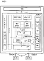
FIG 1 zeigt ein Kommunikationssystem KS, in dem beispielhaft ein Teilnehmeranschlußmodul SLMO dargestellt ist. An das Kommunikationssystem KS bzw. das Teilnehmeranschlußmodul SLMO sind Kommunikationsendgeräte KE anschließbar. Die Kommunikationsendgeräte KE werden im Stimulus-Verfahren (S) - alle Einstellungen des Kommunikationsendgerätes KE werden vom Kommunikationssystem KS aus vorgenommen - oder nach einem Protokoll-Verfahren (P) - nach Übermitteln einer Signalisierungsnachricht si nimmt das Kommunikationsendgerät KE selbständig die Einstellungen vor - betrieben. Die Signalisierungsnachrichten si werden über einen über jeweils einen Kommunikationsanschluß KA geführten Signalisierungskanal D zusammen mit den Nutzinformationen ni - beispielsweise digitalisierte Sprachinformationen - übertragen. Im Kommunikationssystem KS ist das Teilnehmeranschlußmodul SLMO mit einer das Kommunikationssystem KS koordinierende und steuernde Steuereinrichtung CCU verbunden. FIG 1 zeigt weiterhin die Programmstruktur des beispielhaft dargestellten Teilnehmeranschlußmoduls SLMO, wobei in den weiteren nicht dargestellten Teilnehmeranschlußmodulen SLMO eine gleichartige Programmstruktur realisiert ist. Die Programmstruktur ist in verschiedene nachstehend erläuterte Prozesse strukturiert. Die Prozesse sind als eigenständige Tasken organisiert, die bezüglich der Nachrichtenverarbeitung - Nachrichten von der zentralen Steuereinrichtung CCU oder von den Kommunikationsendgeräten KE oder zu diesen - unterschiedliche Prioritätsebenen aufweisen.1 shows a communication system KS, in which a subscriber line module SLMO is shown as an example. Communication terminals KE can be connected to the communication system KS or the subscriber line module SLMO. The communication terminals KE are operated in the stimulus method (S) - all settings of the communication terminal KE are made from the communication system KS - or according to a protocol method (P) - after transmitting a signaling message si, the communication terminal KE independently carries out the settings. The signaling messages si are transmitted via a signaling channel D, each via a communication connection KA, together with the useful information ni, for example digitized voice information. In the communication system KS, the subscriber line module SLMO is connected to a control device CCU that coordinates and controls the communication system KS. 1 further shows the program structure of the subscriber line module SLMO shown as an example, a similar program structure being implemented in the other subscriber line modules SLMO (not shown). The program structure is structured in various processes explained below. The processes are organized as independent tasks, which have different priority levels with regard to message processing - messages from the central control device CCU or from the communication terminals KE or to these.
Die Kommunikation zwischen der zentralen Steuereinrichtung CCU und dem Teilnehmeranschlußmodul SLMO wird in diesem durch die beiden HDLC-Übertragungsroutinen HDLC TASK, HDLC INT realisiert. Beide HDLC-Übertragungsroutinen HDLC TASK, HDLC INT enthalten Treiberroutinen für den Nachrichtenverkehr, wobei die erste HDLC-Übertragungsroutine HDLC TASK für das Senden von Nachrichten m zu der zentralen Steuereinrichtung CCU und die zweite HDLC-Übertragungsroutine HDLC INT für das Empfangen von Nachrichten m von der zentrale Steuereinrichtung CCU zuständig ist. Im Teilnehmeranschlußmodul SLMO werden die Anforderungen der HDLC-Übertragungsroutinen HDLC TASK, HDLC INT mit höchster Priorität verarbeitet. Die beiden HDLC-Übertragungsroutinen HDLC TASK, HDLC INT kommunizieren mit einem Vorfeld-Device-Handler VDH, in dem eine vermittlungstechnische Vorverarbeitung (Call Processing) der von den Kommunikationsendgeräten KE übermittelten Signalisierungsinformationen si durchgeführt wird. Im Vorfeld-Device-Handler VDH ist ein durch ein Programmmodul IWU-S realisierter Prozeß für die Vorverarbeitung von vermittlungstechnischen Prozeduren eines Stimulus-Kommunikationsendgerätes KE(S) und des weiteren ein durch ein Programm-IWU-S0 realisierter Prozeß für die Verarbeitung der vermittlungstechnischen Meldungen eines "Protokoll"-Kommunikationsendgerätes KE(P) - z.B. ein ISDN-Kommunikationsendgerät mit einer S0-Schnittstelle - vorgesehen. Des weiteren ist insbesondere für das Bilden von speziellen Meldungen für die Anzeigeeinrichtungen von Stimulus-Kommunikationsendgeräten KE(S) ein Schicht-3-Programm L3P enthalten, das insbesondere mit dem Programm IWU-S über eine definierte Schnittstelle IS kommuniziert. Das Schicht-3-Programm L3P ist vorzugsweise für das Bilden und das Handling von Anzeigemeldungen für alle an das jeweilige Teilnehmeranschlußmodul SLMO angeschlossene Stimulus-Kommunikationsendgeräte KE(S) vorgesehen, wobei der Informationsinhalt dieser Anzeigemeldungen in den jeweiligen Stimulus-Kommunikationsendgeräten KE in einer Anzeigeeinrichtung optisch angezeigt wird.Communication between the central control device CCU and the subscriber line module SLMO is implemented in this by the two HDLC transmission routines HDLC TASK, HDLC INT. Both HDLC transmission routines HDLC TASK, HDLC INT contain driver routines for message traffic, the first HDLC transmission routine HDLC TASK for sending messages m to the central control unit CCU and the second HDLC transmission routine HDLC INT for receiving Messages m from the central control unit CCU is responsible. In the subscriber line module SLMO, the requirements of the HDLC transmission routines HDLC TASK, HDLC INT are processed with the highest priority. The two HDLC transmission routines HDLC TASK, HDLC INT communicate with an apron device handler VDH, in which a processing preprocessing (call processing) of the signaling information si transmitted by the communication terminals KE is carried out. In the apron device handler VDH is a process realized by a program module IWU-S for the preprocessing of switching procedures of a stimulus communication terminal KE (S) and further a process realized by a program IWU-S0 for processing the switching messages a "protocol" communication terminal KE (P) - for example an ISDN communication terminal with an S0 interface - is provided. Furthermore, a layer 3 program L3P, which communicates in particular with the program IWU-S via a defined interface IS, is included in particular for the formation of special messages for the display devices of stimulus communication terminals KE (S). The layer 3 program L3P is preferably provided for the formation and handling of display messages for all stimulus communication terminals KE (S) connected to the respective subscriber line module SLMO, the information content of these display messages being visual in the respective stimulus communication terminals KE in a display device is shown.
In einem weiteren Schicht-2-Programm L2P ist die Schicht 2 gemäß dem OSI-Referenzmodell für Benutzer-Netz-Signalisierung und Informationstransfer sowohl in Richtung zentraler Steuereinrichtung CCU als auch in Richtung der Kommunikationsendgeräte KE realisiert. Diese Schicht 2 übernimmt für die Schicht 3, d.h. die Vermittlungsschicht das gesicherte Übermitteln der Signalisierungsinformationen si in beide Richtungen.In a further layer 2 program L2P, layer 2 is implemented according to the OSI reference model for user network signaling and information transfer both in the direction of the central control device CCU and in the direction of the communication terminals KE. This layer 2 takes over for the layer 3, ie the network layer, the secure transmission of the signaling information si in both directions.
Das Schicht-2-Programm L2P kommuniziert mit einem Schicht-1-Programm L1P, das das Bindeglied zu den schaltungstechnischen Übertragungs- und Stromversorgungseinrichtungen für die jeweilig angeschlossenen Kommunikationsendgeräte KE darstellt. Durch dieses Schicht-1-Programm L1P werden die Kommunikationsanschlüsse KA aktiviert und deaktiviert, Testschleifen gesteuert sowie ein Powermanagement durchgeführt.The layer 2 program L2P communicates with a layer 1 program L1P, which represents the link to the circuitry transmission and power supply devices for the respectively connected communication terminals KE. This layer 1 program L1P activates and deactivates the communication connections KA, controls test loops and performs power management.
Für die Verwaltung und den Betrieb der Mikroprozessorsystem-Ressourcen ist ein Betriebssystem COSMOS realisiert. Durch dieses Betriebssystem COSMOS werden auch die Speicherelemente SE eines Speicherelementepools SEP verwaltet und den jeweiligen Prozessen bzw. Programmodulen nach entsprechender Anforderung - insbesondere bei der Nachrichtenverarbeitung - temporär zugeteilt - der Speicherelementepool SEP mit seinen Speicherelementen SE ist durch ein strichliertes Rechteck im Betriebssystemblock angedeutet. Des weiteren ist im Betriebssystem COSMOS ein Zähler Z vorgesehen, mit dessen Hilfe die noch freien Speicherelemente SE des Speicherelementepools SEP gezählt werden.An operating system COSMOS is implemented for the administration and operation of the microprocessor system resources. This operating system COSMOS also manages the memory elements SE of a memory element pool SEP and temporarily allocates them to the respective processes or program modules, as required - in particular for message processing - the memory element pool SEP with its memory elements SE is indicated by a dashed rectangle in the operating system block. Furthermore, a counter Z is provided in the operating system COSMOS, with the aid of which the still free memory elements SE of the memory element pool SEP are counted.
Für die betriebstechnische Steuerung, d.h. die betriebstechnischen Einstellungen des Teilnehmeranschlußmoduls SLMO ist ein Sicherungs- und Betriebstechnikprogrammodul STB vorgesehen. Von diesem Betriebstechnikprogrammodul STB werden auch alle Betriebsparameter hinsichtlich der für die Überlasterkennung erforderlichen Auslastungsgrenzen zur Verfügung gestellt. Dies sind insbesondere Betriebsparameter über eine Mikroprozessorsystem-Auslastungsgrenze GZS, die Grenzgesamtnachrichtenlänge gznl, und der Intervallzeiten IV sowie einer Speicherelementepool-Auslastungsgrenze GZ.For operational control, i.e. The operational settings of the SLMO subscriber connection module are provided by a safety and operating technology program module STB. This operating technology program module STB also provides all operating parameters with regard to the load limits required for overload detection. These are, in particular, operating parameters via a microprocessor system utilization limit GZS, the total limit message length gznl, and the interval times IV and a memory element pool utilization limit GZ.
Des weiteren werden im Schicht-2-Programm L2P die Nachrichtenlängen L der jeweils in Richtung Kommunikationsendgerät KE zu übermittelnden Signalisierungsnachrichten si festgestellt und an eine Überlastroutine URL übermittelt. Für das Erkennen des Überlastzustandes weist die Überlastroutine URL eine Speicherelementepool-Meßroutine SEP-MR, eine Signalisierungskanal-Meßroutine D-MR, ein Überlastprogramm UP sowie eine kommunikationsanschlußbezogene Signalisierungskanal-Meßroutine KAD-MR auf. Der Überlaststatus wird insbesondere dem durch das Programm IWU-S realisierten Prozeß für die Steuerung von Stimulus-Kommunikationsendgeräten KE(S) durch Stufe1- und Stufe2-Überlastmeldungen um1,2 mitgeteilt. Durch Übermitteln der Überlastmeldungen um1,2 wird das Aussenden von Anzeigemeldungen an einzelne, besonders überlastete Kommunikationsanschlüsse KA oder an alle oder das Aussenden aller Signalisierungsmeldungen si an einzelne oder besonders überlastete Kommunikationsanschlüsse KA unterbunden.Furthermore, the message lengths L of the signaling messages si to be transmitted in each case in the direction of the communication terminal KE are ascertained in the layer 2 program L2P and transmitted to an overload routine URL. To detect the overload condition, the overload routine URL has a memory element pool measuring routine SEP-MR, a signaling channel measuring routine D-MR, an overload program UP and a communication port-related signaling channel measuring routine KAD-MR. The overload status is communicated in particular to the process implemented by the program IWU-S for the control of stimulus communication terminals KE (S) by level 1 and level 2 overload messages by 1.2. By transmitting the overload messages by 1.2, the transmission of display messages to individual, particularly overloaded communication connections KA or to all or the transmission of all signaling messages si to individual or particularly overloaded communication connections KA is prevented.
Die in den Meßroutinen D-MR, SEP-MR und im Überlastprogramm UP realisierten Verfahren sind in den FIG 2 bis 6 dargestellt. Die jeweiligen Ablaufdiagramme sind im wesentlichen sich selbst erläuternd und zeigen insbesondere die zur Erkennung einer Überlast führenden Verfahrensschritte bezüglich einer Messung der Prozeßauslastung des Mikroprozessors MPS, der Messung der Signalisierungskanalauslastung, der Messung der Auslastung des Speicherelementepools SEP, der Messung der kommunikationsanschluß-spezifischen Signalisierungskanalauslastung und einem Erkennen der Überlast einschließlich unterschiedlicher Überlastungsstufen. In FIG 6 ist das Umstellen bzw. das Zurückstellen auf den nicht überlasteten Zustand des Teilnehmernanschlußmoduls SLMO nicht dargestellt, wobei bei einem nicht ständigen Vorliegen der Überlastung des Mikroprozessorsystems MPS und des Signalisierungskanals D während des Überlastungsintervalls ZVU eine die Rücksetzung der ersten Überlaststufe bewirkende Rücksetzmeldung rsm gebildet und an den durch das Programmodul IWU-S realisierten Prozeß übermittelt wird. Analog hierzu wird bei Nicht-Vorliegen einer Speicherelementepool-Überlastmeldung sepum eine die Rücksetzung der zweiten Überlastungsstufe bewirkende Rucksetzmeldung rsm gebildet und an die betroffenen Einheiten übermittelt. Liegt keine die Überlastung anzeigende Meldung um1,2 vor, wird folglich auch kein Überlastungszustand des Teilnehmeranschlußmodul SLMO gemeldet, d.h. das Teilnehmeranschlußmodul SLMO befindet sich im Normalbetrieb. In FIG 6 ist dieser Zusammenhang durch die Bezeichnung rsm angedeutet, wobei jedoch unterschiedliche Verfahrensabläufe - nicht dargestellt - zu berücksichtigen sind.The methods implemented in the measurement routines D-MR, SEP-MR and in the overload program UP are shown in FIGS. 2 to 6. The respective flowcharts are essentially self-explanatory and in particular show the method steps leading to the detection of an overload with regard to measuring the process load of the microprocessor MPS, measuring the signaling channel load, measuring the load of the memory element pool SEP, measuring the communication port-specific signaling channel load and one Detect overload, including different levels of overload. FIG. 6 does not show the changeover or the resetting to the non-overloaded state of the subscriber line module SLMO, wherein if the overload of the microprocessor system MPS and the signaling channel D is not constant during the overload interval ZVU, a reset message rsm which causes the first overload stage to be reset is formed and is transmitted to the process implemented by the program module IWU-S. Analogously to this, if a storage element pool overload message sepum is not present, a reset of the second overload level is effected Reset message rsm formed and transmitted to the affected units. If there is no message indicating the overload by 1.2, there is consequently no overload status of the subscriber line module SLMO, ie the subscriber line module SLMO is in normal operation. This relationship is indicated in FIG. 6 by the designation rsm, although different process sequences - not shown - must be taken into account.
Claims (18)
Applications Claiming Priority (2)
| Application Number | Priority Date | Filing Date | Title |
|---|---|---|---|
| DE19534940A DE19534940C2 (en) | 1995-09-20 | 1995-09-20 | Method for recognizing overload situations in subscriber line modules of a communication system |
| DE19534940 | 1995-09-20 |
Publications (3)
| Publication Number | Publication Date |
|---|---|
| EP0765093A2 true EP0765093A2 (en) | 1997-03-26 |
| EP0765093A3 EP0765093A3 (en) | 2000-01-05 |
| EP0765093B1 EP0765093B1 (en) | 2006-10-18 |
Family
ID=7772690
Family Applications (1)
| Application Number | Title | Priority Date | Filing Date |
|---|---|---|---|
| EP96113852A Expired - Lifetime EP0765093B1 (en) | 1995-09-20 | 1996-08-29 | Method for detecting overload situations in subscriber connection modules of a communication system |
Country Status (4)
| Country | Link |
|---|---|
| US (1) | US5964840A (en) |
| EP (1) | EP0765093B1 (en) |
| CN (1) | CN1085455C (en) |
| DE (1) | DE19534940C2 (en) |
Cited By (1)
| Publication number | Priority date | Publication date | Assignee | Title |
|---|---|---|---|---|
| DE10056523A1 (en) * | 2000-11-15 | 2002-05-23 | Tenovis Gmbh & Co Kg | Method for generating charge information in a telecommunication network |
Families Citing this family (3)
| Publication number | Priority date | Publication date | Assignee | Title |
|---|---|---|---|---|
| US6718170B1 (en) * | 1999-07-01 | 2004-04-06 | Qualcomm Incorporated | Dynamic allocation of microprocessor resources in a wireless communication device |
| US20020120702A1 (en) * | 2001-02-26 | 2002-08-29 | Schiavone Vincent J. | Method and apparatus for dynamic prioritization of electronic mail messages |
| US8954549B2 (en) * | 2010-06-07 | 2015-02-10 | Red Hat Israel, Ltd. | Automatic detection of a network interface on a host for accessing networked storage |
Citations (5)
| Publication number | Priority date | Publication date | Assignee | Title |
|---|---|---|---|---|
| EP0121236A2 (en) * | 1983-03-31 | 1984-10-10 | Siemens Aktiengesellschaft | Circuit arrangement for telecommunication installations, especially for telephone exchanges comprising information processors and devices for overload control |
| US4511762A (en) * | 1983-06-06 | 1985-04-16 | Siemens Corporate Research & Support, Inc. | Overload detection and control system for a telecommunications exchange |
| EP0316250A2 (en) * | 1987-11-09 | 1989-05-17 | International Business Machines Corporation | Apparatus and method for monitoring workstation controller performance |
| EP0553753A1 (en) * | 1992-01-31 | 1993-08-04 | Siemens Aktiengesellschaft | Private branch exchange with grouped lines |
| GB2278027A (en) * | 1993-04-19 | 1994-11-16 | Hewlett Packard Co | Methods and apparatus for monitoring networks |
Family Cites Families (5)
| Publication number | Priority date | Publication date | Assignee | Title |
|---|---|---|---|---|
| US5313454A (en) * | 1992-04-01 | 1994-05-17 | Stratacom, Inc. | Congestion control for cell networks |
| US5604866A (en) * | 1993-09-30 | 1997-02-18 | Silicon Graphics, Inc. | Flow control system having a counter in transmitter for decrementing and incrementing based upon transmitting and received message size respectively for indicating free space in receiver |
| US5574861A (en) * | 1993-12-21 | 1996-11-12 | Lorvig; Don | Dynamic allocation of B-channels in ISDN |
| JPH088971A (en) * | 1994-06-20 | 1996-01-12 | Nec Corp | Distributed packet exchange and flow control execution controlling method therefor |
| US5487072A (en) * | 1994-06-30 | 1996-01-23 | Bell Communications Research Inc. | Error monitoring algorithm for broadband signaling |
-
1995
- 1995-09-20 DE DE19534940A patent/DE19534940C2/en not_active Expired - Fee Related
-
1996
- 1996-08-29 EP EP96113852A patent/EP0765093B1/en not_active Expired - Lifetime
- 1996-09-19 US US08/715,913 patent/US5964840A/en not_active Expired - Lifetime
- 1996-09-20 CN CN96112344A patent/CN1085455C/en not_active Expired - Lifetime
Patent Citations (5)
| Publication number | Priority date | Publication date | Assignee | Title |
|---|---|---|---|---|
| EP0121236A2 (en) * | 1983-03-31 | 1984-10-10 | Siemens Aktiengesellschaft | Circuit arrangement for telecommunication installations, especially for telephone exchanges comprising information processors and devices for overload control |
| US4511762A (en) * | 1983-06-06 | 1985-04-16 | Siemens Corporate Research & Support, Inc. | Overload detection and control system for a telecommunications exchange |
| EP0316250A2 (en) * | 1987-11-09 | 1989-05-17 | International Business Machines Corporation | Apparatus and method for monitoring workstation controller performance |
| EP0553753A1 (en) * | 1992-01-31 | 1993-08-04 | Siemens Aktiengesellschaft | Private branch exchange with grouped lines |
| GB2278027A (en) * | 1993-04-19 | 1994-11-16 | Hewlett Packard Co | Methods and apparatus for monitoring networks |
Non-Patent Citations (1)
| Title |
|---|
| HASSELGREN J ET AL: "HANDLING OVERLOAD IN AXE 10" ERICSSON REVIEW, Bd. 72, Nr. 3, Seite 124-131 XP000543265 STOCKHOLM ISSN: 0014-0171 * |
Cited By (2)
| Publication number | Priority date | Publication date | Assignee | Title |
|---|---|---|---|---|
| DE10056523A1 (en) * | 2000-11-15 | 2002-05-23 | Tenovis Gmbh & Co Kg | Method for generating charge information in a telecommunication network |
| DE10056523B4 (en) * | 2000-11-15 | 2006-06-01 | Tenovis Gmbh & Co. Kg | A method for generating charge information in a telecommunications network |
Also Published As
| Publication number | Publication date |
|---|---|
| EP0765093A3 (en) | 2000-01-05 |
| US5964840A (en) | 1999-10-12 |
| DE19534940A1 (en) | 1997-03-27 |
| CN1085455C (en) | 2002-05-22 |
| CN1151642A (en) | 1997-06-11 |
| EP0765093B1 (en) | 2006-10-18 |
| DE19534940C2 (en) | 1998-07-02 |
Similar Documents
| Publication | Publication Date | Title |
|---|---|---|
| DE69632240T2 (en) | Method and system for controlling transmission speeds of sources in ATM networks | |
| DE112010001370B4 (en) | Signal transmission device for an elevator | |
| EP0470283B1 (en) | Method and circuit arrangement for determining the quality of virtual circuits going through an ATM switching arrangement | |
| DE60132312T2 (en) | LOAD CONTROL | |
| EP0510222B1 (en) | Method for overload defence in an exchange of a communication network | |
| EP0765093B1 (en) | Method for detecting overload situations in subscriber connection modules of a communication system | |
| DE69908782T2 (en) | ERROR CONTROL AND CORRECTION IN A DATA COMMUNICATION SYSTEM | |
| EP0591234B1 (en) | Process for detecting the nature of data-falsifying interference | |
| EP0360917B1 (en) | Method and circuit arrangement for controlling a serial interface circuit | |
| DE102020121542A1 (en) | Communication facility, communication system and protocol switching method | |
| DE69731375T2 (en) | Multiple Interrupt Handling Method and Device | |
| DE4417777C2 (en) | Communication system | |
| DE102019218827B3 (en) | METHOD, DEVICE AND SYSTEM FOR OPTIMIZING DATA TRANSFER BETWEEN CONTROL DEVICES AND CLOUD SYSTEMS | |
| DE10325263A1 (en) | Ensuring maximum response times in complex or distributed secure and / or non-secure systems | |
| DE3403454C2 (en) | ||
| DE3233221A1 (en) | CIRCUIT ARRANGEMENT FOR TRANSMITTING SIGNALS BETWEEN SUBSCRIBER CONNECTION LINES AND AT LEAST ONE TRANSMISSION LINE OF A SERVICE-INTEGRATED TELECOMMUNICATION SYSTEM | |
| DE19532929C2 (en) | Procedure for reducing alarm messages in load situations | |
| DE3613898A1 (en) | Communication system having a number of subscriber stations accessing a common transmission network | |
| EP0477613B1 (en) | Procedure for the consistent selection of events occuring in a communications system | |
| DE3311919C2 (en) | ||
| DE69631366T2 (en) | Method and device for correcting transmission errors and detecting errors during the transmission of data via a data transmission medium | |
| EP0385126A2 (en) | In-service monitoring and/or control apparatus for transmission devices of the electrical information transmission technique | |
| DE3110600A1 (en) | STATION FOR REMOTE CONTROL DEVICES | |
| DE10129397C2 (en) | Method for monitoring a high bit rate data transmission and associated components | |
| EP0777361A2 (en) | Apparatus and method for communication between transmission and/or reception station and a switching station |
Legal Events
| Date | Code | Title | Description |
|---|---|---|---|
| PUAI | Public reference made under article 153(3) epc to a published international application that has entered the european phase |
Free format text: ORIGINAL CODE: 0009012 |
|
| AK | Designated contracting states |
Kind code of ref document: A2 Designated state(s): BE FR GB NL |
|
| PUAL | Search report despatched |
Free format text: ORIGINAL CODE: 0009013 |
|
| AK | Designated contracting states |
Kind code of ref document: A3 Designated state(s): BE FR GB NL |
|
| RIC1 | Information provided on ipc code assigned before grant |
Free format text: 7H 04Q 3/545 A, 7H 04Q 11/04 B |
|
| 17P | Request for examination filed |
Effective date: 20000531 |
|
| GRAP | Despatch of communication of intention to grant a patent |
Free format text: ORIGINAL CODE: EPIDOSNIGR1 |
|
| GRAS | Grant fee paid |
Free format text: ORIGINAL CODE: EPIDOSNIGR3 |
|
| GRAA | (expected) grant |
Free format text: ORIGINAL CODE: 0009210 |
|
| AK | Designated contracting states |
Kind code of ref document: B1 Designated state(s): BE FR GB NL |
|
| PG25 | Lapsed in a contracting state [announced via postgrant information from national office to epo] |
Ref country code: NL Free format text: LAPSE BECAUSE OF FAILURE TO SUBMIT A TRANSLATION OF THE DESCRIPTION OR TO PAY THE FEE WITHIN THE PRESCRIBED TIME-LIMIT Effective date: 20061018 |
|
| REG | Reference to a national code |
Ref country code: GB Ref legal event code: FG4D Free format text: NOT ENGLISH |
|
| GBT | Gb: translation of ep patent filed (gb section 77(6)(a)/1977) |
Effective date: 20070104 |
|
| NLV1 | Nl: lapsed or annulled due to failure to fulfill the requirements of art. 29p and 29m of the patents act | ||
| ET | Fr: translation filed | ||
| PLBE | No opposition filed within time limit |
Free format text: ORIGINAL CODE: 0009261 |
|
| STAA | Information on the status of an ep patent application or granted ep patent |
Free format text: STATUS: NO OPPOSITION FILED WITHIN TIME LIMIT |
|
| 26N | No opposition filed |
Effective date: 20070719 |
|
| BERE | Be: lapsed |
Owner name: SIEMENS A.G. Effective date: 20070831 |
|
| PG25 | Lapsed in a contracting state [announced via postgrant information from national office to epo] |
Ref country code: BE Free format text: LAPSE BECAUSE OF NON-PAYMENT OF DUE FEES Effective date: 20070831 |
|
| REG | Reference to a national code |
Ref country code: GB Ref legal event code: 732E Free format text: REGISTERED BETWEEN 20090604 AND 20090610 |
|
| REG | Reference to a national code |
Ref country code: FR Ref legal event code: TP |
|
| REG | Reference to a national code |
Ref country code: FR Ref legal event code: PLFP Year of fee payment: 20 |
|
| PGFP | Annual fee paid to national office [announced via postgrant information from national office to epo] |
Ref country code: FR Payment date: 20150624 Year of fee payment: 20 |
|
| PGFP | Annual fee paid to national office [announced via postgrant information from national office to epo] |
Ref country code: GB Payment date: 20150728 Year of fee payment: 20 |
|
| REG | Reference to a national code |
Ref country code: GB Ref legal event code: PE20 Expiry date: 20160828 |
|
| PG25 | Lapsed in a contracting state [announced via postgrant information from national office to epo] |
Ref country code: GB Free format text: LAPSE BECAUSE OF EXPIRATION OF PROTECTION Effective date: 20160828 |