EP0765645A2 - Femoral component condyle design for knee prosthesis - Google Patents
Femoral component condyle design for knee prosthesis Download PDFInfo
- Publication number
- EP0765645A2 EP0765645A2 EP96307051A EP96307051A EP0765645A2 EP 0765645 A2 EP0765645 A2 EP 0765645A2 EP 96307051 A EP96307051 A EP 96307051A EP 96307051 A EP96307051 A EP 96307051A EP 0765645 A2 EP0765645 A2 EP 0765645A2
- Authority
- EP
- European Patent Office
- Prior art keywords
- tibial
- prosthesis
- coronal
- flexion
- radius
- Prior art date
- Legal status (The legal status is an assumption and is not a legal conclusion. Google has not performed a legal analysis and makes no representation as to the accuracy of the status listed.)
- Granted
Links
Images


Classifications
-
- A—HUMAN NECESSITIES
- A61—MEDICAL OR VETERINARY SCIENCE; HYGIENE
- A61F—FILTERS IMPLANTABLE INTO BLOOD VESSELS; PROSTHESES; DEVICES PROVIDING PATENCY TO, OR PREVENTING COLLAPSING OF, TUBULAR STRUCTURES OF THE BODY, e.g. STENTS; ORTHOPAEDIC, NURSING OR CONTRACEPTIVE DEVICES; FOMENTATION; TREATMENT OR PROTECTION OF EYES OR EARS; BANDAGES, DRESSINGS OR ABSORBENT PADS; FIRST-AID KITS
- A61F2/00—Filters implantable into blood vessels; Prostheses, i.e. artificial substitutes or replacements for parts of the body; Appliances for connecting them with the body; Devices providing patency to, or preventing collapsing of, tubular structures of the body, e.g. stents
- A61F2/50—Prostheses not implantable in the body
- A61F2/60—Artificial legs or feet or parts thereof
- A61F2/64—Knee joints
-
- A—HUMAN NECESSITIES
- A61—MEDICAL OR VETERINARY SCIENCE; HYGIENE
- A61F—FILTERS IMPLANTABLE INTO BLOOD VESSELS; PROSTHESES; DEVICES PROVIDING PATENCY TO, OR PREVENTING COLLAPSING OF, TUBULAR STRUCTURES OF THE BODY, e.g. STENTS; ORTHOPAEDIC, NURSING OR CONTRACEPTIVE DEVICES; FOMENTATION; TREATMENT OR PROTECTION OF EYES OR EARS; BANDAGES, DRESSINGS OR ABSORBENT PADS; FIRST-AID KITS
- A61F2/00—Filters implantable into blood vessels; Prostheses, i.e. artificial substitutes or replacements for parts of the body; Appliances for connecting them with the body; Devices providing patency to, or preventing collapsing of, tubular structures of the body, e.g. stents
- A61F2/02—Prostheses implantable into the body
- A61F2/30—Joints
- A61F2/38—Joints for elbows or knees
Definitions
- This invention relates to implantable bone prostheses, and more particularly to knee joint prostheses.
- Knee arthroplasty is a well known surgical procedure by which a diseased and/or damaged natural knee joint is replaced with a prosthetic knee joint.
- Typical knee prostheses include a femoral component, a patella component, a tibial tray or plateau, and a tibial bearing member.
- the femoral component generally includes a pair of laterally spaced apart condylar portions, the distal surfaces of which articulate with complementary condylar elements formed in a tibial bearing component.
- the tibial bearing member is typically made of an ultrahigh molecular weight polyethylene (UHMWPE). Friction, continuous cycling and stress can cause some erosion and/or fracture of the tibial bearing member, thus leading to wear debris.
- UHMWPE ultrahigh molecular weight polyethylene
- Friction, continuous cycling and stress can cause some erosion and/or fracture of the tibial bearing member, thus leading to wear debris.
- the risk of wear debris can be even greater during malalignment of an artificial knee joint, which can result from normal usage or from imperfect and/or inaccurate implantation of the prosthesis within a patient.
- the load upon the tibial bearing member is not evenly distributed. Instead, excess load is placed on certain areas of the tibial bearing member. This uneven distribution of load (or edge loading) can accelerate the development of wear debris.
- Contact stresses on the tibial bearing member increase substantially with malalignment of the joint, thus increasing the risk that wear debris will develop when a prosthetic knee joint is subjected to malalignment conditions.
- knee joint prostheses with improved performance and a longer use for life. It is also an object of the invention to provide knee joint prostheses having reduced tendency to develop wear debris.
- a further object of the invention is to provide knee joint prostheses which are able to maintain relatively high contact area and low contact stress between femoral and tibial components throughout the normal range of motion and in conditions at malalignment.
- Another object of the invention is to provide knee joint prostheses that exhibit acceptable levels of laxity despite maintaining good tibio-femoral contact area in conditions of flexion.
- the invention provides a knee joint prosthesis in which the articulation surfaces of the femoral and tibial components are configured to maintain good contact area and low contact stress when implanted in a patient.
- the femoral component of the knee joint prosthesis has a proximal surface which is mountable on a distal end of the femur of a patient, and a distal articulation surface.
- the distal articulation surface includes two adjacent, semi-parallel bearing surfaces that form femoral condyles.
- Each femoral condyle is of a curved, convex shape in both the anterior-posterior direction and in the medial-lateral direction.
- each femoral condyle lying in the sagittal plane, in contact with a tibial condylar element, and extending in the anterior-posterior direction is defined by at least two semi-parallel radii wherein a first sagittal radius is more anterior than a second sagittal radius.
- the first and second sagittal radii are offset from one another by the distance between their respective centers of curvature.
- the centers of curvature of the first and second sagittal radii are coplanar.
- each femoral condyle lying in the coronal plane, in contact with a tibial condylar element, and extending in the medial-lateral direction is defined by multiple coronal radii.
- the coronal radii increase in value from a minimum value at an anterior portion of the bearing surface, corresponding to about 0° flexion, to a maximum value at a posterior portion of the bearing surface corresponding to about 60 to 90° flexion.
- the coronal radius is approximately 0.7 to 1.1 inches at its minimum value at an anterior portion of bearing surface, and it increases to a maximum value of about 0.74 to 1.17 inches at a posterior portion of the bearing surface corresponding to about 60° to 90° flexion.
- the maximum value of the coronal radius of the femoral condyles can be approximately equal to, but not greater than, the coronal radius of the tibial insert which the femoral condyles contact.
- the coronal radius remains substantially constant at portions of the bearing surface posterior of the maximum radius value.
- the prosthesis also includes a tibial tray or plateau having a proximal end and a distal end that is mountable on the tibia of the patient. Further, the prosthesis includes a tibial bearing member having a proximal articulation surface and a distal surface that is mountable within the proximal end of the tibial plateau component.
- the proximal articulation surface of the tibial bearing member includes two adjacent tibial condylar elements that seat the adjacent, semi-parallel bearing surfaces of the femoral component.
- Each condylar element of the tibial bearing member is of a curved, concave shape in both the anterior-posterior and medial-lateral directions.
- the prosthesis of the present invention is characterized by improved contact between the femoral condyles and the tibial condylar elements. That is, in conditions of flexion, the tibio-femoral contact area remains approximately equal to the contact area at zero flexion, or the contact area only decreases to an extent less than that typically expected in a knee joint prosthesis.
- contact area between the condyles of the femoral component and the condylar elements of the tibial bearing member, at 0° flexion and without malalignment is in the range of 200 to 400 mm 2 , and typically is about 270 mm 2 .
- the tibio-femoral contact area remains substantially the same throughout the range of motion.
- Typical existing knee prostheses produce a tibio-femoral contact area decrease of about 100 to 200 mm 2 at 60° - 90° flexion.
- the ability to achieve substantially the same tibio-femoral contact area after flexion represents an improvement over many current femoral component designs in which the contact area at 90° flexion drops to about 130 mm 2 or less.
- Such improved contact area at higher degrees of flexion as compared to other femoral component designs, reduces the magnitude of contact stresses that are generated at higher degrees of flexion.
- the present design should therefore result in a reduced tendency to develop wear debris and thus a longer lifetime for the prosthetic joint.
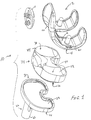
- Figure 1 is an exploded, perspective view of an artificial knee joint illustrating the femoral component, the patella component, the tibial bearing member and the tibial plateau.
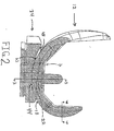
- Figure 2 is a side view from the medial side, with cross-section, of an artificial knee femoral component positioned adjacent a prosthetic tibial bearing member in perfect alignment and at 0° flexion.
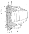
- Figure 3 is an anterior view, with cross-section at lines 3-3, of the artificial knee femoral component shown in Figure 2 positioned adjacent a prosthetic tibial bearing member in a condition of perfect alignment and at 0° flexion.
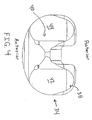
- Figure 4 is a top view of the prosthetic tibial bearing member shown in Figure 1.
- Figure 5 is a sectional view, in the sagittal plane, of a femoral component and tibial bearing member constructed according to the present invention.
- Figure 6 is a partial sectional view at lines 6-6, in the coronal plane, of the femoral component illustrated in Figure 2.
- Figure 7 is a side view (from the medial side) of the femoral component of the present invention mounted adjacent to a tibial bearing member at 90° flexion.
- Figure 8 is a bar graph comparing contact area at high and low flexion angles for knee joint prostheses according to the present invention and prior art knee joint prostheses.
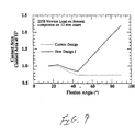
- Figure 9 is a graph comparing the ratio of contact area through the range of motion to contact area at 15° flexion plotted against flexion angle for knee joint prostheses according to the present invention and prior art knee joint prostheses.
- Figure 10 is a graph comparing the ratio of contact stress through the range of motion to contact stress at 15° flexion plotted against flexion angle for knee joint prosthesis according to the present invention and prior art knee joint prostheses.
- the present invention provides an improved construction for knee joint prostheses, especially as the femoral component rotates into flexion.
- the design and geometry of the knee joint prosthesis of the invention facilitate greater contact between the femoral and tibial components of the knee joint prosthesis during flexion than that which is typically associated with knee prostheses.
- FIG. 1 illustrates four components found in a knee joint prosthesis 10 constructed according to the present invention.
- a patella component 11 is adapted to seat against an anterior portion of the femoral component 12.
- the femoral component 12 includes an inferior surface 16 which is mountable within the distal end of a patient's femur and a superior articulation surface 18.
- the articulation surface 18 includes adjacent lateral 20 and medial 22 condyles.
- the knee prosthesis 10 also includes a tibial tray or plateau 24, the distal end 26 of which includes a distally extending stem 25 which is mountable within the tibia of a patient.
- the proximal end 30 of the tibial plateau includes a recessed region 32 within which a tibial bearing member 34 is mounted in a mechanical fit.
- Tibial bearing member 34 includes a distal surface 36 mountable within a recessed region 32 of proximal end 30 of tibial plateau 24.
- the proximal surface 38 of tibial bearing member 34 forms an articulation surface 40 that engages and articulates with the articulation surface 18 of femoral component 12.
- the articulation surface 40 of the tibial bearing member 34 includes adjacent lateral 42 and medial 44 condyles. As shown in Figure 3, the lateral and medial condyles 20, 22 of the femoral component 12 mount in engagement with the lateral and medial condyles 42, 44 of tibial bearing member 34.
- a tibial component of an artificial knee joint can be formed as a single piece which includes portions that correspond to tibial tray component 24 and tibial bearing member 34.
- such single piece units are manufactured of ultrahigh molecular weight polyethylene.
- the condyles 20, 22 of femoral component 12 and the condyles 42, 44 of tibial bearing member 34 are configured such that a relatively large contact area is achieved when the condyles of the femoral component and the condyles of the tibial bearing member engage each other. Greatest contact area is achieved in conditions of perfect alignment. throughout the range of motion of the knee joint. In conditions of malalignment, including varus-valgus lift and internal-external rotation, contact area of existing knee prostheses typically decreases substantially.
- perfect alignment refers to a condition where the knee joint is subjected to 0° varus-valgus lift, and 0° internal-external rotation throughout the anatomic range of flexion-extension (i.e., about -10° to 120°).
- FIGS 2 through 7 illustrate the femoral component 12 of the invention, including condyles 20, 22.
- Each condyle 20, 22 is generally ellipsoid in shape and is of a curved, convex shape in both the anterior-posterior direction and in the medial-lateral direction.
- the curvature of the articulation surface 23 of each condyle 20, 22 lying in the sagittal plane, in contact with the condyles 42, 44 tibial bearing member, and extending in the anterior-posterior direction is defined by at least two semi-parallel radii wherein a first sagittal radius is more anterior than a second sagittal radius.
- the first, more anterior sagittal radius (R 1 ) is offset from the second sagittal radius (R 2 ) by the distance between their respective centers of curvature (C 1 , C 2 ).
- the curvature of the articulation surface 23 lying in the sagittal plane for each condyle 20, 22 can be defined by approximately 4 radii.
- the critical surface geometry is that which relates to the portion of the condyles 20, 22 which contact the condyles 42, 44 of the tibial bearing member 34.
- a first sagittal radius (R 1 ) covers an intermediate portion of the articulation surface 23 of each condyle 20, 22 in the sagittal plane and extending in the anterior-posterior direction.
- the articulation surface 23 of condyles 20, 22 defined by the first sagittal radius (R 1 ) contacts the articulation surface 40 of tibial bearing member 34 during flexion of the knee between approximately 0° and 40°.
- the first sagittal radius (R 1 ) is in the range of approximately 1.020 to 1.885 inches.
- the second sagittal radius (R 2 ) covers a more posterior portion of the articulation surface 23 of condyles 20, 22 lying in the sagittal plane and extending in the anterior-posterior direction.
- the articulation surface 23 of condyles 20, 22 defined by R 2 typically contacts the articulation surface 40 of tibial bearing member 34 during flexion of the knee greater than about 40°.
- the second sagittal radius (R 2 ) preferably has a value of approximately 0.6 to 1.2 inches, and more preferably due to anatomic constraints, a value of about 0.7 to 1.1 inches.
- the first and second sagittal radii originate from their respective centers of curvature (C 1 , C 2 ).
- the centers of curvature C 1 and C 2 are collinear and the center of curvature for R 2 (C 2 ) is more posterior than the center of curvature for R 1 (C 1 ).
- the values of the first and second sagittal radii are, to some extent, dependent upon the size of the femoral component.
- femoral components are available in different sizes to accommodate the anatomies of different patients.
- Femoral components can have dimensions in which the largest width (in the anterior-posterior dimension) ranges from about 50 to 74 mm, and in which the largest width (in the medial-lateral dimension) ranges from about 54 to 78 mm.
- Table 1 illustrates approximate values for the first and second sagittal radii with varying femoral component sizes.
- Tibio-femoral conformity is the ratio of the femoral radius to the tibial radius in the medial-lateral plane and in the anterior-posterior plane.
- medial-lateral conformity can be expressed as R fM / L R iM / L where R fM/L is the femoral radius in the medial-lateral plane and R iM/L is the tibial insert radius measured in the medial-lateral plane.
- conformity in the anterior-posterior plane can be expressed as R fA / P R iA / P Where R fA/P is the femoral radius in the anterior-posterior plane and R iA/P is the tibial radius in the anterior-posterior plane.
- a decrease in conformity between the two components results in a decrease in contact area and an increase in contact stress.
- Conformity can be measured at any flexion angle.
- the anterior-posterior conformity of existing knee prostheses decreases as the femoral component rotates into flexion. This results from a decrease in the femoral radius in the sagittal plane at higher flexion angles, due to anatomic constraints.
- the decrease in anterior-posterior conformity is offset by an increase in medial-lateral conformity. This is accomplished by gradually increasing the coronal radii of the bearing surface 23 of condyles 20, 22 from anterior to posterior portions of the bearing surface 23 of condyles 20, 22. The increasing coronal radius (in the anterior-posterior direction) results in an increase in medial-lateral conformity. This increase in medial-lateral conformity causes the tibio-femoral contact area to remain more stable (i.e., to remain constant or to decrease to a lesser extent) as compared to representative existing knee joint prostheses.
- Figure 3 illustrates the curvature of bearing surface 23 of condyles 20, 22 lying in the coronal plane and extending in the medial-lateral direction at a point on the bearing surface corresponding to approximately 0° flexion.
- the curvature at this point on the bearing surface is defined by the initial coronal radius (R c(i) ).
- the initial coronal radius is in the range of about 0.70 to 1.1 inches.
- the value of the coronal radius increases gradually from the initial coronal radius as one moves along the bearing surface 23 from this anterior portion of the articulation surface to posterior portions of the articulation surface.
- the coronal radius increases by approximately 4 to 7% from the R c(i) to a point on the bearing surface corresponding to flexion of approximately 90°.
- Figure 6 illustrates the curvature of the bearing surface 23 of condyles 20, 22 lying in the coronal plane and extending in the medial-lateral direction at a point on the bearing surface 23 corresponding to approximately 45° flexion.
- the value of the coronal radius at this point on the articulation surface preferably is in the range of about 0.74 to about 1.17 inches, and most preferably is about 0.848 inch.
- the coronal radius is independent of the size of the femoral component or tibial bearing member used in the joint prosthesis.
- tibial bearing member 34 includes adjacent lateral 42 and medial 44 tibial condylar elements that are generally ellipsoid and are configured to seat and articulate with condyles 20, 22 of femoral component 12.
- the tibial condylar elements 42, 44 preferably are of a curved, concave shape.
- the articulation surface 46 of tibial condylar elements 42, 44 is characterized by a curved, concave surface in both the medial-lateral and anterior-posterior directions.
- the curvature of the tibial condylar elements 42, 44 lying in the sagittal plane and extending in the anterior-posterior direction is defined by a sagittal radius (R s ).
- this radius is approximately 104% to 120% of the first sagittal radius (R 1 ) of the condylar elements 20, 22 of femoral component 12.
- the curvature of the condyles 42, 44 of the tibial bearing member 34 lying in the coronal plane and extending in the medial-lateral direction is defined by a coronal radius (R c ).
- the coronal radius of the condyles 42, 44 of the tibial bearing member preferably is approximately 120% to 152% of the initial coronal radius R c(i) of the condyles 20, 22 of the femoral component 12.
- the knee joint prosthesis 10 of the present invention provides many advantages. As noted above, the tibial-femoral contact area is improved and contact stress is reduced. A major improvement in contact area is evident during flexion. While many knee joint prostheses experience dramatic decrease in tibio-femoral contact area during flexion (on the order of about 40%), the present knee prosthesis is less susceptible to dramatic decreases in tibio-femoral contact area.
- Figure 8 compares predicted contact area for knee joint prostheses made according to a representative existing design and the present invention (varying coronal radius condyle design) at low flexion (about 15°) through high flexion (about 90°).
- the data was generated using as a sample a medium size representative existing design (i.e., P.F.C. Knee System available from Johnson & Johnson Professional. Inc.) and a knee joint prosthesis constructed according to the present invention.
- the knee joint prosthesis constructed according to the present invention was a medium size prosthesis having a minimum and maximum femoral condyle radii of 0.800 to 0.832 inches, respectively.
- Figures 9 and 10 illustrate data obtained by plotting the ratio of contact area to contact area at 15° flexion versus flexion angle ( Figure 9) and contact stress to contact area at 15° flexion versus flexion angle ( Figure 10) for both the current design and a conventional design.
- the design and geometry of the articulation surfaces of the femoral component and tibial bearing member of the knee prostheses made according to the present invention lends itself to use with a variety of different constructions for a knee joint prosthesis. That is, the articulation surface design and geometry described herein may be incorporated to knee joint prostheses such as cruciate retaining knee prostheses, cruciate sacrificing knee prostheses, meniscal bearing prostheses, revision prostheses, hinge prostheses, and unicondylar prostheses.
- the knee prostheses of the invention can be made from a variety of biocompatible materials having high strength, durability and resistance to wear debris.
- materials include metal alloys such as cobalt-chromium alloy, titanium-aluminum-vanadium alloy, stainless steel, ceramics, and other materials that are well known for use in the manufacture of implantable bone prostheses.
- the femoral component and tibial plateau are made from metal alloys such as cobalt-chromium alloy while the tibial bearing member is made from polymers such as ultra-high molecular weight polyethylene.
Abstract
Description
- This invention relates to implantable bone prostheses, and more particularly to knee joint prostheses.
- Joint replacement surgery is quite common and enables many individuals to function normally when otherwise it would not be possible to do so. Artificial joints are normally composed of metallic, ceramic and/or plastic components that are fixed to existing bone.
- Knee arthroplasty is a well known surgical procedure by which a diseased and/or damaged natural knee joint is replaced with a prosthetic knee joint. Typical knee prostheses include a femoral component, a patella component, a tibial tray or plateau, and a tibial bearing member. The femoral component generally includes a pair of laterally spaced apart condylar portions, the distal surfaces of which articulate with complementary condylar elements formed in a tibial bearing component.
- In a properly functioning artificial knee joint, the condylar portions of the femoral component must slide and roll freely over the articulation surface formed by the condylar elements of the tibial bearing member. Natural friction within a replaced, artificial joint can lead to the development of wear debris in which minute particles of debris (e.g., metal or plastic from the prosthesis) become dislodged and migrate within the joint. The phenomenon of wear debris within artificial joints is a serious problem that can inhibit the proper mechanical functioning of the joint. Moreover, wear debris can lead to osteolysis and bone deterioration. When wear debris develops within an artificial joint. surgical removal of the debris or subsequent replacement of the artificial joint is often necessary.
- During normal usage of a properly implanted prosthetic knee joint, load and stress are placed on the tibial bearing member. The tibial bearing member is typically made of an ultrahigh molecular weight polyethylene (UHMWPE). Friction, continuous cycling and stress can cause some erosion and/or fracture of the tibial bearing member, thus leading to wear debris. The risk of wear debris can be even greater during malalignment of an artificial knee joint, which can result from normal usage or from imperfect and/or inaccurate implantation of the prosthesis within a patient. As a result of malalignment, the load upon the tibial bearing member is not evenly distributed. Instead, excess load is placed on certain areas of the tibial bearing member. This uneven distribution of load (or edge loading) can accelerate the development of wear debris. Contact stresses on the tibial bearing member increase substantially with malalignment of the joint, thus increasing the risk that wear debris will develop when a prosthetic knee joint is subjected to malalignment conditions.
- Contact stresses on the tibial bearing member also tend to increase when the prosthetic knee joint is rotated into flexion. This increased contact stress results from a corresponding decrease in tibio-femoral contact area.
- There is thus a need for knee joint prostheses that have reduced tendency to develop wear debris due to the maintenance of good contact area and low contact stress between femoral and tibial components, even during the dynamics of daily activity and in various conditions of flexion and malalignment.
- Accordingly, it is an object of the present invention to provide knee joint prostheses with improved performance and a longer use for life. It is also an object of the invention to provide knee joint prostheses having reduced tendency to develop wear debris. A further object of the invention is to provide knee joint prostheses which are able to maintain relatively high contact area and low contact stress between femoral and tibial components throughout the normal range of motion and in conditions at malalignment. Another object of the invention is to provide knee joint prostheses that exhibit acceptable levels of laxity despite maintaining good tibio-femoral contact area in conditions of flexion. These and other objects will be apparent from the description that follows.
- The invention provides a knee joint prosthesis in which the articulation surfaces of the femoral and tibial components are configured to maintain good contact area and low contact stress when implanted in a patient. The femoral component of the knee joint prosthesis has a proximal surface which is mountable on a distal end of the femur of a patient, and a distal articulation surface. Preferably the distal articulation surface includes two adjacent, semi-parallel bearing surfaces that form femoral condyles. Each femoral condyle is of a curved, convex shape in both the anterior-posterior direction and in the medial-lateral direction. The curvature of each femoral condyle lying in the sagittal plane, in contact with a tibial condylar element, and extending in the anterior-posterior direction is defined by at least two semi-parallel radii wherein a first sagittal radius is more anterior than a second sagittal radius. The first and second sagittal radii are offset from one another by the distance between their respective centers of curvature. Preferably, the centers of curvature of the first and second sagittal radii are coplanar.
- The curvature of each femoral condyle lying in the coronal plane, in contact with a tibial condylar element, and extending in the medial-lateral direction is defined by multiple coronal radii. The coronal radii increase in value from a minimum value at an anterior portion of the bearing surface, corresponding to about 0° flexion, to a maximum value at a posterior portion of the bearing surface corresponding to about 60 to 90° flexion.
- The coronal radius is approximately 0.7 to 1.1 inches at its minimum value at an anterior portion of bearing surface, and it increases to a maximum value of about 0.74 to 1.17 inches at a posterior portion of the bearing surface corresponding to about 60° to 90° flexion. Alternatively, the maximum value of the coronal radius of the femoral condyles can be approximately equal to, but not greater than, the coronal radius of the tibial insert which the femoral condyles contact. The coronal radius remains substantially constant at portions of the bearing surface posterior of the maximum radius value.
- The prosthesis also includes a tibial tray or plateau having a proximal end and a distal end that is mountable on the tibia of the patient. Further, the prosthesis includes a tibial bearing member having a proximal articulation surface and a distal surface that is mountable within the proximal end of the tibial plateau component. The proximal articulation surface of the tibial bearing member includes two adjacent tibial condylar elements that seat the adjacent, semi-parallel bearing surfaces of the femoral component. Each condylar element of the tibial bearing member is of a curved, concave shape in both the anterior-posterior and medial-lateral directions.
- The prosthesis of the present invention is characterized by improved contact between the femoral condyles and the tibial condylar elements. That is, in conditions of flexion, the tibio-femoral contact area remains approximately equal to the contact area at zero flexion, or the contact area only decreases to an extent less than that typically expected in a knee joint prosthesis. Preferably, contact area between the condyles of the femoral component and the condylar elements of the tibial bearing member, at 0° flexion and without malalignment, is in the range of 200 to 400 mm2, and typically is about 270 mm2. Preferably the tibio-femoral contact area remains substantially the same throughout the range of motion. Typical existing knee prostheses produce a tibio-femoral contact area decrease of about 100 to 200 mm2 at 60° - 90° flexion. The ability to achieve substantially the same tibio-femoral contact area after flexion represents an improvement over many current femoral component designs in which the contact area at 90° flexion drops to about 130 mm2 or less. Such improved contact area at higher degrees of flexion, as compared to other femoral component designs, reduces the magnitude of contact stresses that are generated at higher degrees of flexion. The present design should therefore result in a reduced tendency to develop wear debris and thus a longer lifetime for the prosthetic joint.
- Figure 1 is an exploded, perspective view of an artificial knee joint illustrating the femoral component, the patella component, the tibial bearing member and the tibial plateau.
- Figure 2 is a side view from the medial side, with cross-section, of an artificial knee femoral component positioned adjacent a prosthetic tibial bearing member in perfect alignment and at 0° flexion.
- Figure 3 is an anterior view, with cross-section at lines 3-3, of the artificial knee femoral component shown in Figure 2 positioned adjacent a prosthetic tibial bearing member in a condition of perfect alignment and at 0° flexion.
- Figure 4 is a top view of the prosthetic tibial bearing member shown in Figure 1.
- Figure 5 is a sectional view, in the sagittal plane, of a femoral component and tibial bearing member constructed according to the present invention.
- Figure 6 is a partial sectional view at lines 6-6, in the coronal plane, of the femoral component illustrated in Figure 2.
- Figure 7 is a side view (from the medial side) of the femoral component of the present invention mounted adjacent to a tibial bearing member at 90° flexion.
- Figure 8 is a bar graph comparing contact area at high and low flexion angles for knee joint prostheses according to the present invention and prior art knee joint prostheses.
- Figure 9 is a graph comparing the ratio of contact area through the range of motion to contact area at 15° flexion plotted against flexion angle for knee joint prostheses according to the present invention and prior art knee joint prostheses.
- Figure 10 is a graph comparing the ratio of contact stress through the range of motion to contact stress at 15° flexion plotted against flexion angle for knee joint prosthesis according to the present invention and prior art knee joint prostheses.
- The present invention provides an improved construction for knee joint prostheses, especially as the femoral component rotates into flexion. The design and geometry of the knee joint prosthesis of the invention facilitate greater contact between the femoral and tibial components of the knee joint prosthesis during flexion than that which is typically associated with knee prostheses.
- Figure 1 illustrates four components found in a knee
joint prosthesis 10 constructed according to the present invention. A patella component 11 is adapted to seat against an anterior portion of thefemoral component 12. Thefemoral component 12 includes aninferior surface 16 which is mountable within the distal end of a patient's femur and asuperior articulation surface 18. Thearticulation surface 18 includesadjacent lateral 20 and medial 22 condyles. Theknee prosthesis 10 also includes a tibial tray orplateau 24, thedistal end 26 of which includes a distally extending stem 25 which is mountable within the tibia of a patient. Theproximal end 30 of the tibial plateau includes a recessedregion 32 within which atibial bearing member 34 is mounted in a mechanical fit. -
Tibial bearing member 34 includes adistal surface 36 mountable within a recessedregion 32 ofproximal end 30 oftibial plateau 24. Theproximal surface 38 oftibial bearing member 34 forms anarticulation surface 40 that engages and articulates with thearticulation surface 18 offemoral component 12. Thearticulation surface 40 of thetibial bearing member 34 includesadjacent lateral 42 and medial 44 condyles. As shown in Figure 3, the lateral andmedial condyles femoral component 12 mount in engagement with the lateral andmedial condyles tibial bearing member 34. - Although not illustrated, it is understood that a tibial component of an artificial knee joint can be formed as a single piece which includes portions that correspond to
tibial tray component 24 andtibial bearing member 34. Typically, such single piece units are manufactured of ultrahigh molecular weight polyethylene. - The
condyles femoral component 12 and thecondyles tibial bearing member 34 are configured such that a relatively large contact area is achieved when the condyles of the femoral component and the condyles of the tibial bearing member engage each other. Greatest contact area is achieved in conditions of perfect alignment. throughout the range of motion of the knee joint. In conditions of malalignment, including varus-valgus lift and internal-external rotation, contact area of existing knee prostheses typically decreases substantially. The term "perfect alignment", as used herein refers to a condition where the knee joint is subjected to 0° varus-valgus lift, and 0° internal-external rotation throughout the anatomic range of flexion-extension (i.e., about -10° to 120°). - Figures 2 through 7 illustrate the
femoral component 12 of the invention, includingcondyles condyle articulation surface 23 of eachcondyle condyles articulation surface 23 lying in the sagittal plane for eachcondyle condyles condyles tibial bearing member 34. A first sagittal radius (R1) covers an intermediate portion of thearticulation surface 23 of eachcondyle articulation surface 23 ofcondyles articulation surface 40 oftibial bearing member 34 during flexion of the knee between approximately 0° and 40°. The first sagittal radius (R1) is in the range of approximately 1.020 to 1.885 inches. - The second sagittal radius (R2) covers a more posterior portion of the
articulation surface 23 ofcondyles articulation surface 23 ofcondyles articulation surface 40 oftibial bearing member 34 during flexion of the knee greater than about 40°. The second sagittal radius (R2) preferably has a value of approximately 0.6 to 1.2 inches, and more preferably due to anatomic constraints, a value of about 0.7 to 1.1 inches. - As illustrated in Figure 5, the first and second sagittal radii (R1, R2) originate from their respective centers of curvature (C1, C2). The centers of curvature C1 and C2 are collinear and the center of curvature for R2 (C2) is more posterior than the center of curvature for R1 (C1).
- The values of the first and second sagittal radii (R1, R2) are, to some extent, dependent upon the size of the femoral component. Typically, femoral components are available in different sizes to accommodate the anatomies of different patients. Femoral components can have dimensions in which the largest width (in the anterior-posterior dimension) ranges from about 50 to 74 mm, and in which the largest width (in the medial-lateral dimension) ranges from about 54 to 78 mm. Table 1 illustrates approximate values for the first and second sagittal radii with varying femoral component sizes.
Table 1 Femoral Component Size A-P Width (mm) M-L Width (mm) R 1 Value (inches) R 2 Value (inches) 2 56 60 1.194 0.743 3 61 66 1.321 0.794 4 65 71 1.405 0.828 5 69 73 1.511 0.860 6 74 78 1.750 0.950 - Usually, as a prosthetic knee joint goes into flexion the tibio-femoral contact area decreases and hence contact stress increases. Tibio-femoral conformity is the ratio of the femoral radius to the tibial radius in the medial-lateral plane and in the anterior-posterior plane. Thus, medial-lateral conformity can be expressed as


- Conformity can be measured at any flexion angle. Generally, the anterior-posterior conformity of existing knee prostheses decreases as the femoral component rotates into flexion. This results from a decrease in the femoral radius in the sagittal plane at higher flexion angles, due to anatomic constraints. In the present invention, the decrease in anterior-posterior conformity is offset by an increase in medial-lateral conformity. This is accomplished by gradually increasing the coronal radii of the bearing
surface 23 ofcondyles surface 23 ofcondyles - Figure 3 illustrates the curvature of bearing
surface 23 ofcondyles surface 23 from this anterior portion of the articulation surface to posterior portions of the articulation surface. Generally, the coronal radius increases by approximately 4 to 7% from the Rc(i) to a point on the bearing surface corresponding to flexion of approximately 90°. - Figure 6 illustrates the curvature of the bearing
surface 23 ofcondyles surface 23 corresponding to approximately 45° flexion. The value of the coronal radius at this point on the articulation surface preferably is in the range of about 0.74 to about 1.17 inches, and most preferably is about 0.848 inch. In a preferred embodiment, the coronal radius is independent of the size of the femoral component or tibial bearing member used in the joint prosthesis. - Referring again to Figures 1 through 7,
tibial bearing member 34 includesadjacent lateral 42 and medial 44 tibial condylar elements that are generally ellipsoid and are configured to seat and articulate withcondyles femoral component 12. The tibialcondylar elements condylar elements condylar elements condylar elements femoral component 12. - The curvature of the
condyles tibial bearing member 34 lying in the coronal plane and extending in the medial-lateral direction is defined by a coronal radius (Rc). The coronal radius of thecondyles condyles femoral component 12. - The knee
joint prosthesis 10 of the present invention provides many advantages. As noted above, the tibial-femoral contact area is improved and contact stress is reduced. A major improvement in contact area is evident during flexion. While many knee joint prostheses experience dramatic decrease in tibio-femoral contact area during flexion (on the order of about 40%), the present knee prosthesis is less susceptible to dramatic decreases in tibio-femoral contact area. - Figure 8 compares predicted contact area for knee joint prostheses made according to a representative existing design and the present invention (varying coronal radius condyle design) at low flexion (about 15°) through high flexion (about 90°).
- The data was generated using as a sample a medium size representative existing design (i.e., P.F.C. Knee System available from Johnson & Johnson Professional. Inc.) and a knee joint prosthesis constructed according to the present invention. The knee joint prosthesis constructed according to the present invention was a medium size prosthesis having a minimum and maximum femoral condyle radii of 0.800 to 0.832 inches, respectively.
- Data was generated both through theoretical and experimental methods as follows. Contact stress and contact area were calculated using an approximate elasticity solution to the rigid indenter (femoral condyles) on an elastic bearing surface (tibial insert) problem. This method was adapted from that developed and used by Bartel and his coworkers to investigate the effects of geometry and material properties on contact stress in joint arthroplasty components. (See, Bartel et al., J. Biomech. Eng., Vol. 107, Aug. 1985, pp. 193-199; Bartel, et al., JBJS, Vol. 68-A , No. 7, Sept. 1986, pp. 1041-1051.) Bartel et al. concluded from their investigation that the elasticity solution was valid for use in parameter studies. The load applied during this procedure was 450 pounds. The method has also been shown to be valid for comparative purposes using Tekscan measurement of stress and area as a baseline. The ratio of peak stress to average stress of 1.5 (i.e., peak stress = 1.5 times average stress) as given by Hertzian contact theory has also been shown to agree well with measured and calculated force, area and stress data. (See, Timoshenko et al., Theory of Elasticity, 3rd Edition, McGraw-Hill, New York, 1970, Reissue, 1987.) The experimental data are illustrated in Figure 8.
- As shown in Figure 8 the current femoral condyle design with multiple, increasing coronal radii achieves substantially constant contact area at low and high flexion. In contrast, conventional designs exhibit a dramatic decrease in contact area from low to high flexion conditions.
- Figures 9 and 10 illustrate data obtained by plotting the ratio of contact area to contact area at 15° flexion versus flexion angle (Figure 9) and contact stress to contact area at 15° flexion versus flexion angle (Figure 10) for both the current design and a conventional design.
- The data were developed using the knee joint prostheses described above with respect to Figure 8, and the procedure for obtaining the data is similar to that described for Figure 8.
- The design and geometry of the articulation surfaces of the femoral component and tibial bearing member of the knee prostheses made according to the present invention lends itself to use with a variety of different constructions for a knee joint prosthesis. That is, the articulation surface design and geometry described herein may be incorporated to knee joint prostheses such as cruciate retaining knee prostheses, cruciate sacrificing knee prostheses, meniscal bearing prostheses, revision prostheses, hinge prostheses, and unicondylar prostheses.
- It will be appreciated by those of ordinary skill in art that the knee prostheses of the invention can be made from a variety of biocompatible materials having high strength, durability and resistance to wear debris. Examples of such materials include metal alloys such as cobalt-chromium alloy, titanium-aluminum-vanadium alloy, stainless steel, ceramics, and other materials that are well known for use in the manufacture of implantable bone prostheses. Typically, the femoral component and tibial plateau are made from metal alloys such as cobalt-chromium alloy while the tibial bearing member is made from polymers such as ultra-high molecular weight polyethylene.
- The foregoing description of the invention is presented to indicate the range of constructions to which the invention applies. Variations in the physical architecture and dimensions of the knee prostheses will be apparent to those having ordinary skill in the art based upon the disclosure herein and such variations are considered to be within the scope of the invention in which patent rights are asserted, as set forth in the claims appended hereto. The entirety of all references cited herein is expressly incorporated by reference.
Claims (14)
- A knee joint prosthesis, comprising:a femoral component having an inferior surface mountable on a distal end of the femur of a patient and a superior articulation surface including two adjacent, semi-parallel bearing surfaces, each bearing surface being of a curved, convex shape in both the anterior-posterior direction and in the medial-lateral direction, wherein the curvature of each bearing surface lying in the coronal plane and extending in the medial-lateral direction is defined by multiple coronal radii, wherein the coronal radii increase in value along the bearing surface from an anterior portion of the bearing surface to a posterior portion of the bearing surface;a tibial component having a proximal end and a distal end mountable on the tibia of a patient; anda tibial bearing member having a distal surface mountable within the proximal end of the tibial component and a proximal articulation surface, the proximal articulation surface including adjacent tibial condylar elements that seat adjacent, semi-parallel bearing surfaces of the femoral component.
- The prosthesis of claim 1 wherein the tibial condylar elements of the tibial bearing member are each of a curved, concave shape in both the anterior-posterior and medial-lateral directions and the curvature of the tibial condylar elements lying in the coronal plane and extending in a medial-lateral direction is defined by a tibial coronal radius.
- The prosthesis of claim 2 wherein the curvature of each bearing surface lying in the sagittal plane, in contact with a tibial condylar element, and extending in the anterior-posterior direction is defined by at least two semi-parallel radii wherein a first sagittal radius is more anterior than a second sagittal radius, with the first and second sagittal radii being offset from one another by the distance between their respective centers of curvature.
- The prosthesis of claim 2 wherein the coronal radii increase from a minimum value at an anterior-most point on the bearing surface in contact with the condylar elements of the tibial bearing member at about 0° flexion to a maximum value at a posterior-most point on the bearing surface in contact with the condylar elements of the tibial bearing member corresponding to about 90° flexion.
- The prosthesis of claim 4 wherein the coronal radius remains substantially constant beyond the maximum value at a posterior-most point on the bearing surface in contact with the condylar elements of the tibial bearing member corresponding to about 90° flexion.
- The prosthesis of claim 4 wherein the coronal radii increase by approximately 4 to 7 percent from the minimum radius value to the maximum radius value.
- The prosthesis of claim 4 wherein the minimum radius value is about 0.7 to 1.1 inches.
- The prosthesis of claim 4 wherein the maximum radius value is about 0.74 to about 1.17.
- The prosthesis of claim 4 wherein the maximum radius value is less than or equal to the tibial coronal radius value.
- The prosthesis of claim 4 wherein the maximum radius value is approximately 2% less than the value of the tibial coronal radius.
- The prosthesis of claim 4 wherein the coronal radii range from a minimum value of about 0.80 inch to a maximum value of about 0.85 inch.
- The prosthesis of claim 3 wherein the tibio-femoral contact area of the prosthesis remains substantially the same throughout a range of motion of the prosthesis from 0° flexion to about 90° flexion.
- The prosthesis of claim 12 wherein the tibio-femoral contact area is in the range of about 200 to 400 mm2 throughout the range of motion of the knee joint prosthesis from 0° flexion to about 90° flexion.
- A knee joint prosthesis, comprising:a femoral component having an inferior surface mountable on a distal end of the femur of a patient and a superior articulation surface including at least one bearing surface that is of a curved, convex shape in both the anterior-posterior direction and in the medial-lateral direction, wherein the curvature of the bearing surface lying in the coronal plane and extending in the medial-lateral direction is defined by multiple coronal radii, wherein the coronal radii increase in value from an anterior portion of the bearing surface to a posterior portion of the bearing surface; anda tibial component having means for mounting upon the tibia of a patient and an articulation surface including at least one tibial condylar element that seats the bearing surface of the femoral component.
Applications Claiming Priority (2)
| Application Number | Priority Date | Filing Date | Title |
|---|---|---|---|
| US537241 | 1995-09-29 | ||
| US08/537,241 US5871546A (en) | 1995-09-29 | 1995-09-29 | Femoral component condyle design for knee prosthesis |
Publications (3)
| Publication Number | Publication Date |
|---|---|
| EP0765645A2 true EP0765645A2 (en) | 1997-04-02 |
| EP0765645A3 EP0765645A3 (en) | 1997-11-12 |
| EP0765645B1 EP0765645B1 (en) | 2003-08-20 |
Family
ID=24141823
Family Applications (1)
| Application Number | Title | Priority Date | Filing Date |
|---|---|---|---|
| EP96307051A Expired - Lifetime EP0765645B1 (en) | 1995-09-29 | 1996-09-27 | Femoral component condyle design for knee prosthesis |
Country Status (7)
| Country | Link |
|---|---|
| US (1) | US5871546A (en) |
| EP (1) | EP0765645B1 (en) |
| JP (1) | JP3875323B2 (en) |
| KR (1) | KR100458340B1 (en) |
| AU (1) | AU707380B2 (en) |
| DE (1) | DE69629531T2 (en) |
| ES (1) | ES2205003T3 (en) |
Cited By (12)
| Publication number | Priority date | Publication date | Assignee | Title |
|---|---|---|---|---|
| FR2805455A1 (en) * | 2000-02-24 | 2001-08-31 | Aesculap Sa | FEMORAL COMPONENT OF A THREE-BEND KNEE PROSTHESIS |
| EP1226799A1 (en) * | 2001-01-19 | 2002-07-31 | Keramed Medizintechnik GmbH | Inlay for a knee endoprosthesis |
| EP1033117A3 (en) * | 1999-03-02 | 2003-01-02 | PLUS Endoprothetik AG | Femoral piece |
| WO2003094782A2 (en) * | 2002-05-08 | 2003-11-20 | Mathys Medizinaltechnik Ag | Self-aligning knee prosthesis |
| WO2006092167A1 (en) | 2005-03-02 | 2006-09-08 | Mathys Ag Bettlach | Joint prosthesis comprising an intermediate element having different sliding surfaces |
| US9011547B2 (en) | 2010-01-21 | 2015-04-21 | Depuy (Ireland) | Knee prosthesis system |
| US9204967B2 (en) | 2007-09-28 | 2015-12-08 | Depuy (Ireland) | Fixed-bearing knee prosthesis having interchangeable components |
| US9398956B2 (en) | 2007-09-25 | 2016-07-26 | Depuy (Ireland) | Fixed-bearing knee prosthesis having interchangeable components |
| CN109620480A (en) * | 2019-01-31 | 2019-04-16 | 苏州微创关节医疗科技有限公司 | Single condyle femoral prosthesis and shin bone liner |
| US10265180B2 (en) | 2008-06-30 | 2019-04-23 | Depuy Ireland Unlimited Company | Orthopaedic knee prosthesis having controlled condylar curvature |
| US10729551B2 (en) | 2008-06-30 | 2020-08-04 | Depuy Ireland Unlimited Company | Orthopaedic knee prosthesis having controlled condylar curvature |
| US11337823B2 (en) | 2008-06-30 | 2022-05-24 | Depuy Ireland Unlimited Company | Orthopaedic femoral component having controlled condylar curvature |
Families Citing this family (125)
| Publication number | Priority date | Publication date | Assignee | Title |
|---|---|---|---|---|
| US6695848B2 (en) | 1994-09-02 | 2004-02-24 | Hudson Surgical Design, Inc. | Methods for femoral and tibial resection |
| US8603095B2 (en) | 1994-09-02 | 2013-12-10 | Puget Bio Ventures LLC | Apparatuses for femoral and tibial resection |
| HU219444B (en) * | 1996-02-26 | 2001-04-28 | Gábor Krakovits | Sliding surface for knee-joint prothesis |
| US8882847B2 (en) * | 2001-05-25 | 2014-11-11 | Conformis, Inc. | Patient selectable knee joint arthroplasty devices |
| US9603711B2 (en) * | 2001-05-25 | 2017-03-28 | Conformis, Inc. | Patient-adapted and improved articular implants, designs and related guide tools |
| US8480754B2 (en) | 2001-05-25 | 2013-07-09 | Conformis, Inc. | Patient-adapted and improved articular implants, designs and related guide tools |
| US8735773B2 (en) | 2007-02-14 | 2014-05-27 | Conformis, Inc. | Implant device and method for manufacture |
| US8545569B2 (en) * | 2001-05-25 | 2013-10-01 | Conformis, Inc. | Patient selectable knee arthroplasty devices |
| US8771365B2 (en) * | 2009-02-25 | 2014-07-08 | Conformis, Inc. | Patient-adapted and improved orthopedic implants, designs, and related tools |
| US7618451B2 (en) * | 2001-05-25 | 2009-11-17 | Conformis, Inc. | Patient selectable joint arthroplasty devices and surgical tools facilitating increased accuracy, speed and simplicity in performing total and partial joint arthroplasty |
| US20110071802A1 (en) * | 2009-02-25 | 2011-03-24 | Ray Bojarski | Patient-adapted and improved articular implants, designs and related guide tools |
| US20090222103A1 (en) * | 2001-05-25 | 2009-09-03 | Conformis, Inc. | Articular Implants Providing Lower Adjacent Cartilage Wear |
| US8234097B2 (en) | 2001-05-25 | 2012-07-31 | Conformis, Inc. | Automated systems for manufacturing patient-specific orthopedic implants and instrumentation |
| US8083745B2 (en) * | 2001-05-25 | 2011-12-27 | Conformis, Inc. | Surgical tools for arthroplasty |
| US8617242B2 (en) * | 2001-05-25 | 2013-12-31 | Conformis, Inc. | Implant device and method for manufacture |
| US20110071645A1 (en) * | 2009-02-25 | 2011-03-24 | Ray Bojarski | Patient-adapted and improved articular implants, designs and related guide tools |
| US7534263B2 (en) | 2001-05-25 | 2009-05-19 | Conformis, Inc. | Surgical tools facilitating increased accuracy, speed and simplicity in performing joint arthroplasty |
| US7468075B2 (en) * | 2001-05-25 | 2008-12-23 | Conformis, Inc. | Methods and compositions for articular repair |
| US8556983B2 (en) | 2001-05-25 | 2013-10-15 | Conformis, Inc. | Patient-adapted and improved orthopedic implants, designs and related tools |
| AU772012B2 (en) * | 1998-09-14 | 2004-04-08 | Board Of Trustees Of The Leland Stanford Junior University | Assessing the condition of a joint and preventing damage |
| US7239908B1 (en) * | 1998-09-14 | 2007-07-03 | The Board Of Trustees Of The Leland Stanford Junior University | Assessing the condition of a joint and devising treatment |
| US6165223A (en) | 1999-03-01 | 2000-12-26 | Biomet, Inc. | Floating bearing knee joint prosthesis with a fixed tibial post |
| US6413279B1 (en) | 1999-03-01 | 2002-07-02 | Biomet, Inc. | Floating bearing knee joint prosthesis with a fixed tibial post |
| US6342075B1 (en) * | 2000-02-18 | 2002-01-29 | Macarthur A. Creig | Prosthesis and methods for total knee arthroplasty |
| EP2036495A1 (en) * | 2000-09-14 | 2009-03-18 | The Board of Trustees of The Leland Stanford Junior University | Assessing condition of a joint and cartilage loss |
| AU9088801A (en) | 2000-09-14 | 2002-03-26 | Univ Leland Stanford Junior | Assessing the condition of a joint and devising treatment |
| US6558426B1 (en) | 2000-11-28 | 2003-05-06 | Medidea, Llc | Multiple-cam, posterior-stabilized knee prosthesis |
| US8062377B2 (en) | 2001-03-05 | 2011-11-22 | Hudson Surgical Design, Inc. | Methods and apparatus for knee arthroplasty |
| US7776085B2 (en) * | 2001-05-01 | 2010-08-17 | Amedica Corporation | Knee prosthesis with ceramic tibial component |
| US7695521B2 (en) | 2001-05-01 | 2010-04-13 | Amedica Corporation | Hip prosthesis with monoblock ceramic acetabular cup |
| ATE504264T1 (en) | 2001-05-25 | 2011-04-15 | Conformis Inc | METHODS AND COMPOSITIONS FOR REPAIRING THE SURFACE OF JOINTS |
| US8439926B2 (en) * | 2001-05-25 | 2013-05-14 | Conformis, Inc. | Patient selectable joint arthroplasty devices and surgical tools |
| EP1408874B1 (en) * | 2001-06-14 | 2012-08-08 | Amedica Corporation | Metal-ceramic composite articulation |
| US6821470B2 (en) * | 2001-06-29 | 2004-11-23 | Depuy Products, Inc. | Joint prosthesis molding method |
| US6962607B2 (en) * | 2001-06-30 | 2005-11-08 | Depuy Products, Inc. | Joint replacement prosthesis component with non linear insert |
| CA2501041A1 (en) * | 2002-10-07 | 2004-04-22 | Conformis, Inc. | Minimally invasive joint implant with 3-dimensional geometry matching the articular surfaces |
| WO2004037119A2 (en) * | 2002-10-23 | 2004-05-06 | Mako Surgical Corp. | Modular femoral component for a total knee joint replacement for minimally invasive implantation |
| CN1780594A (en) * | 2002-11-07 | 2006-05-31 | 康复米斯公司 | Methods for determining meniscal size and shape and for devising treatment |
| JP2006510452A (en) * | 2002-12-17 | 2006-03-30 | アメディカ コーポレイション | Total disc implant |
| ES2465090T3 (en) * | 2002-12-20 | 2014-06-05 | Smith & Nephew, Inc. | High performance knee prostheses |
| US7081137B1 (en) | 2003-06-23 | 2006-07-25 | Howmedica Osteonics Corp. | Knee prosthesis with extended range of motion |
| WO2005037147A1 (en) * | 2003-10-17 | 2005-04-28 | Smith & Nephew, Inc. | High flexion articular insert |
| US7261740B2 (en) * | 2003-10-29 | 2007-08-28 | Wright Medical Technology, Inc. | Tibial knee prosthesis |
| US7387644B2 (en) * | 2003-11-07 | 2008-06-17 | University Of Vermont And State Agricultural College | Knee joint prosthesis with a femoral component which links the tibiofemoral axis of rotation with the patellofemoral axis of rotation |
| US8287545B2 (en) | 2004-01-14 | 2012-10-16 | Hudson Surgical Design, Inc. | Methods and apparatus for enhanced retention of prosthetic implants |
| US8114083B2 (en) * | 2004-01-14 | 2012-02-14 | Hudson Surgical Design, Inc. | Methods and apparatus for improved drilling and milling tools for resection |
| US20060030854A1 (en) * | 2004-02-02 | 2006-02-09 | Haines Timothy G | Methods and apparatus for wireplasty bone resection |
| US7857814B2 (en) * | 2004-01-14 | 2010-12-28 | Hudson Surgical Design, Inc. | Methods and apparatus for minimally invasive arthroplasty |
| US7815645B2 (en) * | 2004-01-14 | 2010-10-19 | Hudson Surgical Design, Inc. | Methods and apparatus for pinplasty bone resection |
| US8021368B2 (en) * | 2004-01-14 | 2011-09-20 | Hudson Surgical Design, Inc. | Methods and apparatus for improved cutting tools for resection |
| WO2006110896A2 (en) * | 2005-04-12 | 2006-10-19 | The University Of Vermont And State Agriculture College | Knee prosthesis |
| US7578850B2 (en) * | 2005-04-18 | 2009-08-25 | Uni-Knee, Llc | Unicondylar knee implant |
| US7601154B2 (en) * | 2005-04-18 | 2009-10-13 | Uni-Knee, Llc | Unicondylar knee instrument system |
| US20060235530A1 (en) * | 2005-04-18 | 2006-10-19 | Shelokov Alexis P | Artificial prosthesis |
| US9301845B2 (en) | 2005-06-15 | 2016-04-05 | P Tech, Llc | Implant for knee replacement |
| US20080243258A1 (en) * | 2005-08-24 | 2008-10-02 | Kantilal Hastimal Sancheti | Knee Joint Prosthesis |
| US20080288080A1 (en) * | 2005-08-24 | 2008-11-20 | Kantilal Hastimal Sancheti | Knee joint prosthesis |
| US7413577B1 (en) | 2005-09-22 | 2008-08-19 | Howmedica Osteonics Corp. | Total stabilized knee prosthesis with constraint |
| EP3187153A3 (en) * | 2005-09-30 | 2017-09-20 | ConforMIS, Inc. | Bearing implant |
| US8211181B2 (en) * | 2005-12-14 | 2012-07-03 | New York University | Surface guided knee replacement |
| EP1968497B1 (en) * | 2005-12-15 | 2016-03-16 | Zimmer, Inc. | Distal femoral knee prostheses |
| TWI434675B (en) | 2006-02-06 | 2014-04-21 | Conformis Inc | Patient selectable joint arthroplasty devices and surgical tools |
| US8623026B2 (en) | 2006-02-06 | 2014-01-07 | Conformis, Inc. | Patient selectable joint arthroplasty devices and surgical tools incorporating anatomical relief |
| US20080058945A1 (en) * | 2006-03-13 | 2008-03-06 | Mako Surgical Corp. | Prosthetic device and system and method for implanting prosthetic device |
| EP1996122B1 (en) | 2006-03-21 | 2012-11-21 | DePuy (Ireland) | Moment induced total arthroplasty prosthetic |
| CA2930222A1 (en) | 2006-06-30 | 2008-01-10 | Smith & Nephew, Inc. | Anatomical motion hinged prosthesis |
| US8029574B2 (en) * | 2006-11-07 | 2011-10-04 | Biomedflex Llc | Prosthetic knee joint |
| US8308812B2 (en) | 2006-11-07 | 2012-11-13 | Biomedflex, Llc | Prosthetic joint assembly and joint member therefor |
| EP2081520B1 (en) * | 2006-11-07 | 2017-07-12 | Biomedflex, LLC | Medical implants |
| US8512413B2 (en) | 2006-11-07 | 2013-08-20 | Biomedflex, Llc | Prosthetic knee joint |
| US8070823B2 (en) * | 2006-11-07 | 2011-12-06 | Biomedflex Llc | Prosthetic ball-and-socket joint |
| US9005307B2 (en) | 2006-11-07 | 2015-04-14 | Biomedflex, Llc | Prosthetic ball-and-socket joint |
| US20110166671A1 (en) | 2006-11-07 | 2011-07-07 | Kellar Franz W | Prosthetic joint |
| WO2008157412A2 (en) * | 2007-06-13 | 2008-12-24 | Conformis, Inc. | Surgical cutting guide |
| US8715359B2 (en) | 2009-10-30 | 2014-05-06 | Depuy (Ireland) | Prosthesis for cemented fixation and method for making the prosthesis |
| US7628818B2 (en) * | 2007-09-28 | 2009-12-08 | Depuy Products, Inc. | Fixed-bearing knee prosthesis having interchangeable components |
| US20110035018A1 (en) * | 2007-09-25 | 2011-02-10 | Depuy Products, Inc. | Prosthesis with composite component |
| US8128703B2 (en) * | 2007-09-28 | 2012-03-06 | Depuy Products, Inc. | Fixed-bearing knee prosthesis having interchangeable components |
| US20110035017A1 (en) * | 2007-09-25 | 2011-02-10 | Depuy Products, Inc. | Prosthesis with cut-off pegs and surgical method |
| CN101977570B (en) * | 2008-02-11 | 2013-08-14 | 精密技术公司 | Knee prosthesis system with slope |
| WO2009111626A2 (en) | 2008-03-05 | 2009-09-11 | Conformis, Inc. | Implants for altering wear patterns of articular surfaces |
| CN102006841A (en) * | 2008-03-05 | 2011-04-06 | 肯弗默斯股份有限公司 | Edge-matched articular implant |
| AU2009246474B2 (en) * | 2008-05-12 | 2015-04-16 | Conformis, Inc. | Devices and methods for treatment of facet and other joints |
| US9168145B2 (en) | 2008-06-30 | 2015-10-27 | Depuy (Ireland) | Posterior stabilized orthopaedic knee prosthesis having controlled condylar curvature |
| US9119723B2 (en) | 2008-06-30 | 2015-09-01 | Depuy (Ireland) | Posterior stabilized orthopaedic prosthesis assembly |
| US8206451B2 (en) | 2008-06-30 | 2012-06-26 | Depuy Products, Inc. | Posterior stabilized orthopaedic prosthesis |
| US8192498B2 (en) * | 2008-06-30 | 2012-06-05 | Depuy Products, Inc. | Posterior cructiate-retaining orthopaedic knee prosthesis having controlled condylar curvature |
| US8202323B2 (en) * | 2008-07-16 | 2012-06-19 | Depuy Products, Inc. | Knee prostheses with enhanced kinematics |
| US7981159B2 (en) * | 2008-07-16 | 2011-07-19 | Depuy Products, Inc. | Antero-posterior placement of axis of rotation for a rotating platform |
| US8078440B2 (en) * | 2008-09-19 | 2011-12-13 | Smith & Nephew, Inc. | Operatively tuning implants for increased performance |
| US8157868B2 (en) | 2008-10-10 | 2012-04-17 | New York University | Implants for the treatment of osteoarthritis of the knee |
| JP5404342B2 (en) * | 2009-01-06 | 2014-01-29 | キヤノン株式会社 | Optical scanning device and image forming apparatus using the same |
| US9017334B2 (en) | 2009-02-24 | 2015-04-28 | Microport Orthopedics Holdings Inc. | Patient specific surgical guide locator and mount |
| US8808303B2 (en) | 2009-02-24 | 2014-08-19 | Microport Orthopedics Holdings Inc. | Orthopedic surgical guide |
| US8808297B2 (en) | 2009-02-24 | 2014-08-19 | Microport Orthopedics Holdings Inc. | Orthopedic surgical guide |
| US9078755B2 (en) | 2009-02-25 | 2015-07-14 | Zimmer, Inc. | Ethnic-specific orthopaedic implants and custom cutting jigs |
| EP2419035B1 (en) | 2009-04-16 | 2017-07-05 | ConforMIS, Inc. | Patient-specific joint arthroplasty methods for ligament repair |
| US8915965B2 (en) | 2009-05-07 | 2014-12-23 | Depuy (Ireland) | Anterior stabilized knee implant |
| DE102009029360A1 (en) * | 2009-09-10 | 2011-03-24 | Aesculap Ag | Knee endoprosthesis |
| EP2501340B1 (en) * | 2009-11-16 | 2017-01-18 | New York Society for the Ruptured and Crippled Maintaining the Hospital for Special Surgery | Prosthetic condylar joints with articulating bearing surfaces having a translating contact point during rotation thereof |
| US8900315B2 (en) * | 2009-11-16 | 2014-12-02 | New York Society For The Ruptured And Crippled Maintaining The Hospital For Special Surgery | Constrained condylar knee device |
| EP2509539B1 (en) * | 2009-12-11 | 2020-07-01 | ConforMIS, Inc. | Patient-specific and patient-engineered orthopedic implants |
| JP4995888B2 (en) * | 2009-12-15 | 2012-08-08 | 株式会社神戸製鋼所 | Stainless steel arc welding flux cored wire |
| US8357202B2 (en) * | 2009-12-22 | 2013-01-22 | Zimmer, Gmbh | J-curve for a femoral prosthesis component |
| US8308808B2 (en) | 2010-02-19 | 2012-11-13 | Biomet Manufacturing Corp. | Latent mobile bearing for prosthetic device |
| US10441428B2 (en) | 2010-05-03 | 2019-10-15 | New York University | Early intervention knee implant device and methods |
| AU2011289383B2 (en) | 2010-08-12 | 2016-05-26 | Smith & Nephew, Inc. | Structures for use in orthopaedic implant fixation and methods of installation onto a bone |
| CA2993979A1 (en) | 2010-09-10 | 2012-03-15 | Zimmer Gmbh | Femoral prosthesis with medialized patellar groove |
| EP2438889B1 (en) | 2010-10-05 | 2013-12-11 | Aesculap Ag | Knee joint prosthesis |
| EP2754419B1 (en) | 2011-02-15 | 2024-02-07 | ConforMIS, Inc. | Patient-adapted and improved orthopedic implants |
| US9060868B2 (en) | 2011-06-16 | 2015-06-23 | Zimmer, Inc. | Femoral component for a knee prosthesis with bone compacting ridge |
| US9308095B2 (en) | 2011-06-16 | 2016-04-12 | Zimmer, Inc. | Femoral component for a knee prosthesis with improved articular characteristics |
| US8551179B2 (en) | 2011-06-16 | 2013-10-08 | Zimmer, Inc. | Femoral prosthesis system having provisional component with visual indicators |
| US8932365B2 (en) | 2011-06-16 | 2015-01-13 | Zimmer, Inc. | Femoral component for a knee prosthesis with improved articular characteristics |
| US9486226B2 (en) | 2012-04-18 | 2016-11-08 | Conformis, Inc. | Tibial guides, tools, and techniques for resecting the tibial plateau |
| US9675471B2 (en) | 2012-06-11 | 2017-06-13 | Conformis, Inc. | Devices, techniques and methods for assessing joint spacing, balancing soft tissues and obtaining desired kinematics for joint implant components |
| FR2994644B1 (en) * | 2012-08-24 | 2014-08-29 | Anatomic | PROTHETIC TIBIAL PLUG AND TIBIAL PROTHETIC INSERT FOR IMMOBILIZATION ON SUCH PROTHETIC TIBIAL PLUG |
| US10130375B2 (en) | 2014-07-31 | 2018-11-20 | Zimmer, Inc. | Instruments and methods in performing kinematically-aligned total knee arthroplasty |
| FR3032347B1 (en) * | 2015-02-05 | 2019-12-20 | Assistance Publique - Hopitaux De Paris | TOTAL KNEE PROSTHESIS WITH CERAMIC FRICTION TORQUE ON CERAMIC AND MOBILE CERAMIC TRAY. |
| WO2017058535A1 (en) | 2015-09-29 | 2017-04-06 | Zimmer, Inc. | Tibial prosthesis for tibia with varus resection |
| CN105596122A (en) * | 2016-03-03 | 2016-05-25 | 华中科技大学同济医学院附属同济医院 | Artificial total knee joint prosthesis |
| CN117224288A (en) * | 2016-03-31 | 2023-12-15 | 温晓玉 | Femoral lateral medial and lateral unicondylar prosthesis and femoral trochlear prosthesis |
| US10179052B2 (en) | 2016-07-28 | 2019-01-15 | Depuy Ireland Unlimited Company | Total knee implant prosthesis assembly and method |
| IT201900020616A1 (en) * | 2019-11-08 | 2021-05-08 | Permedica S P A | FEMORAL COMPONENT OF KNEE PROSTHESES AND METHOD OF IMPLEMENTATION |
| DE102021119663A1 (en) * | 2021-07-28 | 2023-02-02 | Aesculap Ag | Medial stabilizing knee endoprosthesis |
Citations (2)
| Publication number | Priority date | Publication date | Assignee | Title |
|---|---|---|---|---|
| US4081866A (en) * | 1977-02-02 | 1978-04-04 | Howmedica, Inc. | Total anatomical knee prosthesis |
| US5387240A (en) * | 1990-11-14 | 1995-02-07 | Arch Development Corporation | Floating bearing prosthetic knee |
Family Cites Families (22)
| Publication number | Priority date | Publication date | Assignee | Title |
|---|---|---|---|---|
| USRE29757E (en) * | 1971-04-21 | 1978-09-12 | Replacements for bicondylar joints in human limbs | |
| US4081860A (en) * | 1977-01-03 | 1978-03-28 | Honeywell Information Systems Inc. | Current mode 4-bit arithmetic logic unit with parity |
| US4470158A (en) * | 1978-03-10 | 1984-09-11 | Biomedical Engineering Corp. | Joint endoprosthesis |
| US4224696A (en) * | 1978-09-08 | 1980-09-30 | Hexcel Corporation | Prosthetic knee |
| US4714472A (en) * | 1987-01-20 | 1987-12-22 | Osteonics Corp. | Knee prosthesis with accommodation for angular misalignment |
| US4888021A (en) * | 1988-02-02 | 1989-12-19 | Joint Medical Products Corporation | Knee and patellar prosthesis |
| US4950298A (en) * | 1988-04-08 | 1990-08-21 | Gustilo Ramon B | Modular knee joint prosthesis |
| US5007933A (en) * | 1989-01-31 | 1991-04-16 | Osteonics Corp. | Modular knee prosthesis system |
| US5201768A (en) * | 1990-01-08 | 1993-04-13 | Caspari Richard B | Prosthesis for implant on the tibial plateau of the knee |
| US5171276A (en) * | 1990-01-08 | 1992-12-15 | Caspari Richard B | Knee joint prosthesis |
| US5330532A (en) * | 1990-11-09 | 1994-07-19 | Chitranjan Ranawat | Knee joint prosthesis |
| DE59107815D1 (en) * | 1991-01-18 | 1996-06-20 | Sulzer Medizinaltechnik Ag | Knee prosthesis |
| GB9102633D0 (en) * | 1991-02-07 | 1991-03-27 | Finsbury Instr Ltd | Knee prosthesis |
| US5236461A (en) * | 1991-03-22 | 1993-08-17 | Forte Mark R | Totally posterior stabilized knee prosthesis |
| US5203807A (en) * | 1991-07-10 | 1993-04-20 | Smith & Nephew Richards Inc. | Knee joint prosthesis articular surface |
| US5133758A (en) * | 1991-09-16 | 1992-07-28 | Research And Education Institute, Inc. Harbor-Ucla Medical Center | Total knee endoprosthesis with fixed flexion-extension axis of rotation |
| US5330534A (en) * | 1992-02-10 | 1994-07-19 | Biomet, Inc. | Knee joint prosthesis with interchangeable components |
| US5344460A (en) * | 1992-10-30 | 1994-09-06 | Encore Orthopedics, Inc. | Prosthesis system |
| ATE197886T1 (en) * | 1992-12-14 | 2000-12-15 | Biomedical Eng Trust Inc | JOINT PROSTHESIS |
| US5370699A (en) * | 1993-01-21 | 1994-12-06 | Orthomet, Inc. | Modular knee joint prosthesis |
| US5358529A (en) * | 1993-03-05 | 1994-10-25 | Smith & Nephew Richards Inc. | Plastic knee femoral implants |
| US5514183A (en) * | 1994-12-20 | 1996-05-07 | Epstein; Norman | Reduced friction prosthetic knee joint utilizing replaceable roller bearings |
-
1995
- 1995-09-29 US US08/537,241 patent/US5871546A/en not_active Expired - Lifetime
-
1996
- 1996-09-17 AU AU65668/96A patent/AU707380B2/en not_active Expired
- 1996-09-23 KR KR1019960041537A patent/KR100458340B1/en not_active IP Right Cessation
- 1996-09-27 EP EP96307051A patent/EP0765645B1/en not_active Expired - Lifetime
- 1996-09-27 ES ES96307051T patent/ES2205003T3/en not_active Expired - Lifetime
- 1996-09-27 JP JP27535096A patent/JP3875323B2/en not_active Expired - Lifetime
- 1996-09-27 DE DE69629531T patent/DE69629531T2/en not_active Expired - Lifetime
Patent Citations (2)
| Publication number | Priority date | Publication date | Assignee | Title |
|---|---|---|---|---|
| US4081866A (en) * | 1977-02-02 | 1978-04-04 | Howmedica, Inc. | Total anatomical knee prosthesis |
| US5387240A (en) * | 1990-11-14 | 1995-02-07 | Arch Development Corporation | Floating bearing prosthetic knee |
Cited By (25)
| Publication number | Priority date | Publication date | Assignee | Title |
|---|---|---|---|---|
| US7306609B2 (en) | 1999-03-02 | 2007-12-11 | Plus Orthopedics Ag | Femoral slideway |
| US9265507B2 (en) | 1999-03-02 | 2016-02-23 | Smith & Nephew Orthopaedics Ag | Femoral slideway |
| US10285817B2 (en) | 1999-03-02 | 2019-05-14 | Smith & Nephew Orthopaedics Ag | Femoral slideway and method |
| EP1033117A3 (en) * | 1999-03-02 | 2003-01-02 | PLUS Endoprothetik AG | Femoral piece |
| US6540787B2 (en) | 2000-02-24 | 2003-04-01 | Aesculap | Femoral component of a knee prosthetic including three curvature radii |
| FR2805455A1 (en) * | 2000-02-24 | 2001-08-31 | Aesculap Sa | FEMORAL COMPONENT OF A THREE-BEND KNEE PROSTHESIS |
| EP1129676A1 (en) * | 2000-02-24 | 2001-09-05 | Aesculap | Femoral piece of a knee prosthesis with three radii of curvature |
| EP1226799A1 (en) * | 2001-01-19 | 2002-07-31 | Keramed Medizintechnik GmbH | Inlay for a knee endoprosthesis |
| WO2003094782A2 (en) * | 2002-05-08 | 2003-11-20 | Mathys Medizinaltechnik Ag | Self-aligning knee prosthesis |
| DE10220591A1 (en) * | 2002-05-08 | 2003-12-04 | Mathys Medizinaltechnik Ag Bet | Joint prosthesis with an intermediate element with different radii of curvature |
| WO2003094782A3 (en) * | 2002-05-08 | 2004-03-04 | Mathys Medizinaltechnik Ag | Self-aligning knee prosthesis |
| DE10220591B4 (en) * | 2002-05-08 | 2004-03-18 | Mathys Medizinaltechnik Ag | Joint prosthesis with an intermediate element with different radii of curvature |
| WO2006092167A1 (en) | 2005-03-02 | 2006-09-08 | Mathys Ag Bettlach | Joint prosthesis comprising an intermediate element having different sliding surfaces |
| DE102005009496B4 (en) * | 2005-03-02 | 2012-12-20 | Mathys Ag Bettlach | Knee joint endoprosthesis with intermediate element with differently designed sliding surfaces |
| US9060866B2 (en) | 2005-03-02 | 2015-06-23 | Mathys Ag Bettlach | Joint prosthesis with intermediate element having differently formed sliding surfaces |
| US9398956B2 (en) | 2007-09-25 | 2016-07-26 | Depuy (Ireland) | Fixed-bearing knee prosthesis having interchangeable components |
| US9204967B2 (en) | 2007-09-28 | 2015-12-08 | Depuy (Ireland) | Fixed-bearing knee prosthesis having interchangeable components |
| US10265180B2 (en) | 2008-06-30 | 2019-04-23 | Depuy Ireland Unlimited Company | Orthopaedic knee prosthesis having controlled condylar curvature |
| US10729551B2 (en) | 2008-06-30 | 2020-08-04 | Depuy Ireland Unlimited Company | Orthopaedic knee prosthesis having controlled condylar curvature |
| US10849760B2 (en) | 2008-06-30 | 2020-12-01 | Depuy Ireland Unlimited Company | Orthopaedic knee prosthesis having controlled condylar curvature |
| US11337823B2 (en) | 2008-06-30 | 2022-05-24 | Depuy Ireland Unlimited Company | Orthopaedic femoral component having controlled condylar curvature |
| US11369478B2 (en) | 2008-06-30 | 2022-06-28 | Depuy Ireland Unlimited Company | Orthopaedic knee prosthesis having controlled condylar curvature |
| US11730602B2 (en) | 2008-06-30 | 2023-08-22 | Depuy Ireland Unlimited Company | Orthopaedic knee prosthesis having controlled condylar curvature |
| US9011547B2 (en) | 2010-01-21 | 2015-04-21 | Depuy (Ireland) | Knee prosthesis system |
| CN109620480A (en) * | 2019-01-31 | 2019-04-16 | 苏州微创关节医疗科技有限公司 | Single condyle femoral prosthesis and shin bone liner |
Also Published As
| Publication number | Publication date |
|---|---|
| JP3875323B2 (en) | 2007-01-31 |
| EP0765645A3 (en) | 1997-11-12 |
| KR100458340B1 (en) | 2005-02-07 |
| DE69629531T2 (en) | 2004-06-24 |
| AU707380B2 (en) | 1999-07-08 |
| EP0765645B1 (en) | 2003-08-20 |
| ES2205003T3 (en) | 2004-05-01 |
| KR970014734A (en) | 1997-04-28 |
| US5871546A (en) | 1999-02-16 |
| DE69629531D1 (en) | 2003-09-25 |
| AU6566896A (en) | 1997-04-10 |
| JPH09108249A (en) | 1997-04-28 |
Similar Documents
| Publication | Publication Date | Title |
|---|---|---|
| EP0765645B1 (en) | Femoral component condyle design for knee prosthesis | |
| US5609643A (en) | Knee joint prosthesis | |
| US9642711B2 (en) | High flexion articular insert | |
| EP0903125B1 (en) | Cushioned joint prosthesis | |
| JP4240886B2 (en) | Tibial component of knee prosthesis | |
| US5658344A (en) | Tibial insert reinforcement pin | |
| US4963152A (en) | Asymmetric prosthetic tibial component | |
| US5723016A (en) | Implantable prosthetic patellar components | |
| EP1591083B1 (en) | Prosthetic knee | |
| Tew et al. | Effect of total knee arthroplasty on maximal flexion | |
| EP1109514B1 (en) | Modular knee implant system | |
| US6143034A (en) | Implantable hinged knee prosthesis having tibial baseplate | |
| EP3626209B1 (en) | Tibial tray with fixation features | |
| US20070100460A1 (en) | Orthopaedic implant systems with anti-abrasion studs | |
| CN111110405B (en) | Artificial knee joint | |
| EP0420460A1 (en) | Knee prosthesis | |
| GB2312166A (en) | Tibial plate for an endoprosthetic knee | |
| GB2277034A (en) | Implantable prosthetic patellar component | |
| Scuderi et al. | The rationale for posterior cruciate substituting total knee arthroplasty | |
| Greenwald et al. | Modular UHMWPE Insert Design Characteristics | |
| AU2014200110A1 (en) | High flexion articular insert |
Legal Events
| Date | Code | Title | Description |
|---|---|---|---|
| PUAI | Public reference made under article 153(3) epc to a published international application that has entered the european phase |
Free format text: ORIGINAL CODE: 0009012 |
|
| AK | Designated contracting states |
Kind code of ref document: A2 Designated state(s): DE ES FR GB IT |
|
| PUAL | Search report despatched |
Free format text: ORIGINAL CODE: 0009013 |
|
| AK | Designated contracting states |
Kind code of ref document: A3 Designated state(s): DE ES FR GB IT |
|
| 17P | Request for examination filed |
Effective date: 19980420 |
|
| 17Q | First examination report despatched |
Effective date: 20000726 |
|
| RAP1 | Party data changed (applicant data changed or rights of an application transferred) |
Owner name: DEPUY PRODUCTS, INC. |
|
| GRAH | Despatch of communication of intention to grant a patent |
Free format text: ORIGINAL CODE: EPIDOS IGRA |
|
| RAP1 | Party data changed (applicant data changed or rights of an application transferred) |
Owner name: DEPUY PRODUCTS, INC. |
|
| GRAH | Despatch of communication of intention to grant a patent |
Free format text: ORIGINAL CODE: EPIDOS IGRA |
|
| GRAA | (expected) grant |
Free format text: ORIGINAL CODE: 0009210 |
|
| AK | Designated contracting states |
Designated state(s): DE ES FR GB IT |
|
| REG | Reference to a national code |
Ref country code: GB Ref legal event code: FG4D |
|
| REF | Corresponds to: |
Ref document number: 69629531 Country of ref document: DE Date of ref document: 20030925 Kind code of ref document: P |
|
| REG | Reference to a national code |
Ref country code: ES Ref legal event code: FG2A Ref document number: 2205003 Country of ref document: ES Kind code of ref document: T3 |
|
| ET | Fr: translation filed | ||
| PLBE | No opposition filed within time limit |
Free format text: ORIGINAL CODE: 0009261 |
|
| STAA | Information on the status of an ep patent application or granted ep patent |
Free format text: STATUS: NO OPPOSITION FILED WITHIN TIME LIMIT |
|
| 26N | No opposition filed |
Effective date: 20040524 |
|
| REG | Reference to a national code |
Ref country code: FR Ref legal event code: PLFP Year of fee payment: 20 |
|
| PGFP | Annual fee paid to national office [announced via postgrant information from national office to epo] |
Ref country code: GB Payment date: 20150923 Year of fee payment: 20 Ref country code: DE Payment date: 20150922 Year of fee payment: 20 Ref country code: ES Payment date: 20150810 Year of fee payment: 20 |
|
| PGFP | Annual fee paid to national office [announced via postgrant information from national office to epo] |
Ref country code: FR Payment date: 20150629 Year of fee payment: 20 |
|
| PGFP | Annual fee paid to national office [announced via postgrant information from national office to epo] |
Ref country code: IT Payment date: 20150925 Year of fee payment: 20 |
|
| REG | Reference to a national code |
Ref country code: DE Ref legal event code: R071 Ref document number: 69629531 Country of ref document: DE |
|
| REG | Reference to a national code |
Ref country code: GB Ref legal event code: PE20 Expiry date: 20160926 |
|
| PG25 | Lapsed in a contracting state [announced via postgrant information from national office to epo] |
Ref country code: GB Free format text: LAPSE BECAUSE OF EXPIRATION OF PROTECTION Effective date: 20160926 |
|
| REG | Reference to a national code |
Ref country code: ES Ref legal event code: FD2A Effective date: 20170103 |
|
| PG25 | Lapsed in a contracting state [announced via postgrant information from national office to epo] |
Ref country code: ES Free format text: LAPSE BECAUSE OF EXPIRATION OF PROTECTION Effective date: 20160928 |