EP0765780B1 - Safety belt combined with air bags - Google Patents
Safety belt combined with air bags Download PDFInfo
- Publication number
- EP0765780B1 EP0765780B1 EP95115391A EP95115391A EP0765780B1 EP 0765780 B1 EP0765780 B1 EP 0765780B1 EP 95115391 A EP95115391 A EP 95115391A EP 95115391 A EP95115391 A EP 95115391A EP 0765780 B1 EP0765780 B1 EP 0765780B1
- Authority
- EP
- European Patent Office
- Prior art keywords
- belt
- impact
- air bags
- solenoid valve
- safety belt
- Prior art date
- Legal status (The legal status is an assumption and is not a legal conclusion. Google has not performed a legal analysis and makes no representation as to the accuracy of the status listed.)
- Expired - Lifetime
Links
Images


Classifications
-
- B—PERFORMING OPERATIONS; TRANSPORTING
- B60—VEHICLES IN GENERAL
- B60R—VEHICLES, VEHICLE FITTINGS, OR VEHICLE PARTS, NOT OTHERWISE PROVIDED FOR
- B60R21/00—Arrangements or fittings on vehicles for protecting or preventing injuries to occupants or pedestrians in case of accidents or other traffic risks
- B60R21/01—Electrical circuits for triggering passive safety arrangements, e.g. airbags, safety belt tighteners, in case of vehicle accidents or impending vehicle accidents
- B60R21/013—Electrical circuits for triggering passive safety arrangements, e.g. airbags, safety belt tighteners, in case of vehicle accidents or impending vehicle accidents including means for detecting collisions, impending collisions or roll-over
-
- B—PERFORMING OPERATIONS; TRANSPORTING
- B60—VEHICLES IN GENERAL
- B60R—VEHICLES, VEHICLE FITTINGS, OR VEHICLE PARTS, NOT OTHERWISE PROVIDED FOR
- B60R21/00—Arrangements or fittings on vehicles for protecting or preventing injuries to occupants or pedestrians in case of accidents or other traffic risks
- B60R21/02—Occupant safety arrangements or fittings, e.g. crash pads
- B60R21/16—Inflatable occupant restraints or confinements designed to inflate upon impact or impending impact, e.g. air bags
- B60R21/18—Inflatable occupant restraints or confinements designed to inflate upon impact or impending impact, e.g. air bags the inflatable member formed as a belt or harness or combined with a belt or harness arrangement
Definitions
- the present invention relates to a safety belt for auto-vehicles to which a plurality of air bags is associated, said plurality of air bags cooperating with the same belt to improve the protection of the passengers from the devastating effects of the road accidents.
- the safety belts fasten the body of the passenger to the seat of the auto-vehicle to prevent the effects of the inertia which acts on the body during an impact of the auto-vehicle against a rigid obstacle or a telescoping.
- the belts are used for preventing the body from colliding against the windscreen (or similar rigid obstacle which is in the internal part of the vehicle) or from being ejected from the vehicle if the doors open suddenly.
- the air bags have the same scope as that of the safety belts; in addition they are used for deadening the impact of the body of the passenger against the windscreen, since they are intruded between the passenger and the obstacle as a cushion filled with gas so as to dissipate the kinetic energy of the body of the passenger by means of their deformation; otherwise said kinetic energy would be dissipated by a fracture or a serious lesion of the same body.
- a second air bag was suggested being mounted between the passenger and the door since said belt is capable of preventing the passenger from being ejected from the vehicle; the second air bag increases the probability of maintaining the passenger in the vehicle if the doors open because of an accident.
- the purpose of the present invention is to remedy these defects.
- the invention solves the problem of creating a safety belt combined with air bags; by means of the invention the result of combining the functions of the belt with those of an air bag (or air bags) is achieved to assure the passengers and/or the driver a higher probability of preventing serious lesions even in the case of accidents at high velocity, since the inflation of the air bag (or of the air bags) is due to the sudden acceleration of the vehicle owing to a lateral or frontal impact or a telescoping.
- a safety belt with air bags is known, e.g. from EP-A-0 652 140.
- the safety belt supports a plurality of air bags which are inflated when the positive or negative acceleration of the vehicle exceeds a pre-established intensity indicating an accident with certainty.
- the air bags swell because of said acceleration.
- the safety belt combined with air bags comprises a male connection which is capable of being inserted in a female connection fastened to the internal part of the floor of the vehicle; the belt consisting of at least one layer of suitable material; said layer houses at least one pipe which extends longitudinally in the internal part of the layer and connects a bottle for a compressed gas to a plurality of air bags; a plurality of housings for said air bags adhering to the side of the belt which is faced towards the external part of the body of the passenger and/or the driver, each of said housings presenting a wall with low mechanical resistance through which said air bags protrude when inflated; sensors of impact are further provided to indicate an impact of the vehicle, said sensors indicate a frontal or lateral impact or a telescoping and control electrical contacts to send a signal to a solenoid valve in order to control the outlet valve of the bottle for the compressed gas to be sent to the air bags.
- Figs from 1 to 6 represent a first embodiment of a belt 1 in different scales.
- the belt 1 is fitted with a male connection 2 and presents three housings 3 in the side faced towards the external part of the body of the driver; each of the housings 3 houses an air bag 4 and is fastened to the side of a first layer 5 of suitable material which is opposite to the side of the same layer 5 which adheres to a second layer 6 which is supported by the body of the passenger or the driver.
- Each of the housings 3 presents a wall with low mechanical resistance 7, through which the air bag 4 protrudes when inflated. The choice of the position of the wall with low resistance 7 allows the air bag 4 to protrude with facility from the housings 3 which house it, and to take a pre-established spatial disposition.
- the belt 1 consists of a first 5 and a second 6 mating and parallel layers (Fig.2).
- the first layer 5 wraps a part of a pipe 8 to send the compressed gas to a plurality of air bags 4 housed in the housings 3. Therefore, the pipe 8 extends longitudinally in the internal part of the first layer 5 which adheres to the second layer 6; in addition the pipe 8 is connected to a plurality of connecting pipes 9, each of which is used for inflating an air bag 4; said pipes 9 cross the first layer 5 in a direction perpendicular to the direction of the pipe 8 and are placed in the internal part of the second layer 5.
- the second layer 6 is completely identical to the single layer which forms the traditional belts.
- a first air bag 4' opens in the frontal part and other air bags 4'' open in lateral parts of the belt 1 so as to wrap the body of the passenger (or the driver) completely and to protect it from the effects of the impact.
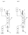
- Figs 7 and 8 show a second embodiment of the belt 1.
- a first air bag 4' opens in the frontal part and is fed by a first pipe 8 connected to a first air bag 4' by means of a first connecting pipe 9;
- second air bags 4'' open in the lateral parts of the belt 1 and are fed by a second pipe 8' connected to said second air bags 4'' by means of second connecting pipes 9'.
- the second air bags 4'' are fitted with overflow valves 10 which partially deflate said second air bags 4'' a few instants after the accident so that the driver can see the road and control the drive.
- the sensors of impact shown in the figures are so shaped that the solenoid valve does not open the outlet valve of the bottle 37 in the case of sudden acceleration or deceleration owing to manoeuvres of the vehicle or a sudden braking.
- An acceleration consists of a change of velocity of the vehicle both in intensity and in direction; for this reason a frontal or lateral impact or a telescoping are the cause for a very strong acceleration which is sensed by the sensors of impact described in this text.
- Figs from 9 to 12 represent a sensor of impact with inertial working.
- the sensor presents a ponderous sphere 11 which slides in a groove 12 made in a body 13, the groove 12 defining the direction D of the movement of the sphere 11.
- the body 13 is housed in a box 14; the body 13 and the box 14 consist of an insulating material and present two holes for two conductors 15 and 16 which connect a battery 17 to a metal plate 18 fastened to an internal wall of the box 14 and an elastic metal thin plate 19 to a solenoid valve 20, respectively.
- the sphere 11 is held in a first position by an elastic tie rod 21 and by a notch 22 so that the thin plate 19 is detached from the metal plate 18.
- the notch 22 houses the sphere 11 and defines the position of the sphere 11 during the normal movement of the vehicle to maintain said sphere 11 near the thin plate 19 in order to shorten the operating time on said thin plate 19.
- the notch 22 establishes a threshold of potential energy which is exceeded by the energy transmitted to the sphere 11 during the accident.
- the sphere 11 is stressed by the inertia and comes out of the notch 22; owing to this stress the sphere 11 stresses the elastic tie rod 21 and pushes the thin plate 19 against the plate 18 to close the circuit which connects the battery 17 to the solenoid valve 20.
- a plurality of devices shown in Figs from 9 to 12 is used, said devices being oriented in several directions which allow to sense these impacts.
- Figs from 13 to 16 represent sensors of impact with inertial working, in which the mass consists of the body of the passenger and/or of the driver.
- Fig.13 shows schematically the male element connecting the belt to the female element fastened to the internal part of the floor of the vehicle.
- the structures illustrated in this Figure are used for demonstrating how it is possible to inflate an air bag by using the force of traction T which acts on the branch of the belt fastened to the same male element.
- the belt 1 is fastened to a bracket 122 on which a sliding sleeve 23 is mounted which is stressed by the force of traction T applied to a branch 24 of the belt 1.
- Two electrical contacts 25 and 26 adhere to a frontal internal wall 27 of the bracket 122, the first contact 25 is connected to the battery 17 of the vehicle and the second contact 26 is connected to a power stage 28.
- the first plate 29 is mechanically connected to the sleeve 23 by connecting means 31 and 31', each of the connecting means 31 and 31' crosses a slot 32, 33 so that the plate 29 moves with the sleeve 23; elastic pushing means 34 are provided between the first plate 29 and the second plate 30.
- the solidarity between the second plate 30 and the bracket 122 is due to two pins 35 and 36 which have a pre-established resistance to searing stress.
- a battery of accumulators 17 feeds the power stage 28 which is used for supplying the power necessary to energise the solenoid valve 20 which controls the outlet valve of a bottle 37.
- Said outlet valve controls the flow of the compressed gas to be sent to the air bag 4 (4',4''); for this reason when the solenoid valve 20 is not energised the outlet valve of the bottle 37 is closed and when the solenoid valve 20 is energised the outlet valve of the bottle 37 is open to send the compressed gas to the air bag 4 through the pipe 8.
- a pressure is provided which is sufficiently high to allow the sudden inflation of the air bag 4.
- Fig.14 the same elements are represented as in Fig.13. Forces of traction of the hand of the driver or the passenger were applied to the sensor of impact; therefore, a little displacement (towards right) of the sleeve 23, of the connecting means 31, 31' in the slots 32, 33 and of the first plate 29 has taken place; however, the forces of traction T are too weak to break the pins 35 and 36; for this reason the pins 35 and 36 limit the movement of the first plate 29 with respect to the second plate 30.
- the elastic pushing means 34 moved by the first plate 29 transmit to the second plate 30 a force, the intensity of which is equal to the forces of traction T for this event; consequently, the pins 35 and 36, which have a pre-established resistance to the searing stress, break.
- the plate 29 keeps pushing the plate 30 through the elastic pushing means 34 until the plate 30 touches the electrical contacts 25 and 26.
- the circuit which feeds the solenoid valve 20 closes and the energised solenoid valve 20 opens the outlet valve of the bottle 37 to send the compressed gas to the air bag 4 (4',4'') through the pipe 8 (or 8').
- a part of the pins 35 and 36 remains in the bracket 122 and a part in the second plate 30.
- Fig.16 discloses a synthesis of the previous description.
- the same elements of Figs 13, 14 and 15 are represented, but the solenoid valve 20 presents a more real aspect.
- the solenoid valve 20 is fed by the power stage 28, for this reason it is earthed by means of a resistance 39, and a diode 38 prevents extra-currents at the start of the energising of the solenoid valve 20 so that no sparking, which is very dangerous in these difficult situations, occurs.
- a sensor of impact was created which acts on the solenoid valve 20 in function of the inertial movement of the driver and/or the passenger with respect to the vehicle; this sensor of impact is capable of sensing the sudden and very high changes of velocity (both in direction and intensity) of the vehicle owing to an accident by using the body of the driver and/or of the passenger as inertial mass which generates a force equal to the product of the same mass by acceleration, in accordance with the first law of the dynamic.
- a control device 40 is represented which is used for closing or opening the solenoid valve 20.
- the device 40 is substantially a relay which energises the solenoid valve 20 when one of the devices shown in the Figs from 19 to 26 is used. If the battery 17 is sufficiently powerful, the use of the power stage 28 is not necessary.
- a solenoid 41 associated with an air gap 42 is housed in a box 43 and energised by the current coming from the battery 17.
- a switch 44 when a switch 44 is closed, the energised solenoid 41 opens a movable armature 45 which is between a first contact 46 and a second contact 47; in this way the current coming from the battery 17 does not feed the power stage 28 and the solenoid valve 20.
- the solenoid valve 20 closes the outlet valve of the bottle 37 when energised and opens the outlet valve of the bottle 37 when not energised; in absence of the device 40 the opening of the outlet valve of the bottle 37 takes place when the battery 17 is disconnected for a check up of the electrical feeding system of the engine with consequent sending of the compressed gas to the air bag 4 through the pipe 8.
- Figs from 19 to 22 and from 25 to 26 show the male connection 2 which connects the belt 1 to the female element 48 fastened to the internal part of the floor of the vehicle. These Figures represent the switch 44 of Figs 17 and 18.
- the belt 1 is connected to the male connection 2 through a connecting bracket 49 which is so shaped to lengthen in consequence of a traction T of the belt owing to a lateral or frontal impact or a telescoping.
- the bracket 49 presents an upper part 50 connected to the belt 1 and a lower part 51 connected to the male connection 2; both upper 50 and lower 51 parts consist of a metal material capable of conducing and are connected each other by means of a bent slab 52 of plastic material which does not conduct and presents a high mechanical resistance.
- Three magnets 53 are integral with the upper part 50 and three magnets 53' are integral with the lower part 51. The free ends of the magnets 53 and 53' are in contact with each other to cooperate with the bent slab 52 to stand the stresses of low intensity which take place when the belt 1 is manoeuvred by the driver or the passenger.
- the magnets 53 and 53' when in contact, assure the conduction of the electrical energy from the upper part 50, connected to the battery 17, to the lower part 51, connected to the switch 44 of the device 40 represented in Figs 17 and 18.
- the bent slab 52 Owing to a stress of high intensity due to a lateral or frontal impact or a telescoping, the bent slab 52 lengthens and takes the form shown in Fig.22, for this reason, the upper part 50 and the lower part 51 disjoint and move with the relevant magnets 53 and 53'.
- the slab 52 must be shape-retaining if stressed by a manoeuvre of the belt 1 and capable of warping because of the stresses owing to an impact.
- the slab 52 of Figs 21 and 22 is bent to allow its elongation when it is stressed by the traction T.
- Such an elongation may be achieved by using a slab (not shown) consisting of a material which has a suitable modulus of elasticity.
- Figs 23 and 24 represent a third connection of a belt 1 stressed by a moderate traction and by a traction due to an impact, respectively.
- the belt 1 is connected to the male connection 2 by means of a connecting bracket 49 which is so shaped to lengthen in consequence of a traction of the belt owing to a lateral or frontal impact or a telescoping.
- the bracket 49 presents an upper part 50 connected to the belt 1 and a lower part 51 connected to the male connection 2; both upper 50 and lower 51 parts are connected to each other by a bent slab 52 consisting of a material with high mechanical resistance (see Figs 21 and 22).
- a first shield 54 is integral with the upper part 50 and a second shield 55 is integral with the lower part 51.
- the free ends of the shields 54 and 55 are in contact to prevent a beam of light (visible or of a different frequency) from passing from a sender 56 to a receiver 57.
- a beam of light visible or of a different frequency
- the bent slab 52 lengthens and takes the form shown in Fig.22; consequently the upper part 50 and the lower part 51 disjoint and move with the relevant shields 54 and 55.
- the free ends of the shields 54 and 55 are no longer in contact and the receiver 57 receives the light from the sender 56 and starts to conduce so that the current coming from the battery 17 feeds the power stage 28 and the solenoid valve 20, and the compressed gas from the bottle 37 inflates the air bag 4 suddenly.
- Figs 25 and 26 represent a fourth connection of a belt 1 stressed by a very moderate traction and by a traction due to an impact, respectively.
- the connection presents an upper part 50, connected to the belt 1 and a lower part 51 connected to the male connection 2.
- the connection of both upper 50 and lower 51 parts is due to two magnets 53 and 53' fastened to the upper part 50 and lower 51, respectively.
- the free ends of the magnets 53 and 53' are in contact with each other to stand the stresses of low intensity which take place when the belt 1 is manoeuvred by the driver or the passenger.
- the magnets 53 and 53' when in contact, assure the conduction of the electrical energy from the upper part 50, connected to the battery 17, to the lower part 51, connected to the device 40 represented in Figs 17 and 18.
- the magnets 53 and 53' Owing to a stress of high intensity due to a lateral or frontal impact or a telescoping the magnets 53 and 53' disjoint and move with the relevant upper 50 and lower 51 parts.
- the free ends of the magnets 53 and 53' are no longer in contact and the movable armature 45 of the device 40 is placed so as to connect the first contact 46 to the second contact 47 so that the current coming from the battery 17 can feed the power stage 28 and the solenoid valve 20 or the solenoid valve 20 directly.
- the compressed gas of the bottle 37 inflates the air bag 4 suddenly.
- Figs from 27 to 30 represent a sensor of impact which uses vibration to sense frontal or lateral impacts or telescoping.
- This device consists of two boxes 58 and 58' fastened to the bodywork 59 of the auto-vehicle (for example to the vertical rod of a door).
- the box 58 is used for sensing the lateral impacts and the box 58' is used for sensing the frontal impacts or the telescoping.
- two elastic tangs 60 and 60' are provided which are supported overhanging by the lower wall 61 of the box 58 (or 58'); at the ends of the elastic tangs 60 and 60' electrical contacts 62 and 62' are provided which are used for closing the circuit which connects the battery 17 to the solenoid valve 20, the elastic tangs 60 and 60' consisting of a conductor of electricity. Insulators 63 and 63' are further provided to insulate the elastic tangs 60 and 60' from the wall 61 of the box 58 (or 58').
- the tang 60 or 60' forms a system capable of oscillating if stressed by a vibratory movement, the intensity of which exceeds a pre-established threshold.
- the oscillations take place in a plane parallel to the narrow section of the tang 60 or 60'; when a frontal or lateral impact or a telescoping causes a shock wave which propagates in the bodywork, the amplitude of the oscillations is sufficient to bring the contact 62 to the contact 62' so as to close the circuit connecting the battery 17 to the solenoid valve 20 to inflate the air bags 4.
- a plurality of the devices shown in Figs from 27, to 30 is used.
- the belt 1 consists of a single layer of a suitable material which wraps the pipe 8 longitudinally and which supports a plurality of housings or boxes 3 for the air bags 4 on the side which is faced towards the external part of the body of the passenger and/or of the driver after the unwinding of the belt 1.
- a circuit with electronic components is used for performing the same functions of the circuit represented in Figs 17 and 18.
Abstract
Description
- The present invention relates to a safety belt for auto-vehicles to which a plurality of air bags is associated, said plurality of air bags cooperating with the same belt to improve the protection of the passengers from the devastating effects of the road accidents.
- At present auto-vehicles are fitted with safety belts and air bags.
The safety belts fasten the body of the passenger to the seat of the auto-vehicle to prevent the effects of the inertia which acts on the body during an impact of the auto-vehicle against a rigid obstacle or a telescoping. The belts are used for preventing the body from colliding against the windscreen (or similar rigid obstacle which is in the internal part of the vehicle) or from being ejected from the vehicle if the doors open suddenly. - The air bags have the same scope as that of the safety belts; in addition they are used for deadening the impact of the body of the passenger against the windscreen, since they are intruded between the passenger and the obstacle as a cushion filled with gas so as to dissipate the kinetic energy of the body of the passenger by means of their deformation; otherwise said kinetic energy would be dissipated by a fracture or a serious lesion of the same body.
- At present the safety belts and the air bags are mounted on the auto-vehicle separately, for this reason it is not possible to define any synergy among the advantageous effects of these devices of safety; therefore each of these devices operates without considering the operation of the other. This lack of synergy is the cause for the low efficacy in the protection of the passenger; in particular during the accidents at moderate velocity the kinetic energy is dissipated by the belt nearly completely, but during the accidents at high velocity the kinetic energy is dissipated by the air bag nearly completely; for this reason the belt can be inefficient or even the cause for damage. In addition, in the case of telescoping or lateral impacts the traditional air bag do not swell.
- A second air bag was suggested being mounted between the passenger and the door since said belt is capable of preventing the passenger from being ejected from the vehicle; the second air bag increases the probability of maintaining the passenger in the vehicle if the doors open because of an accident.
- The purpose of the present invention is to remedy these defects. The invention, as claimed, solves the problem of creating a safety belt combined with air bags; by means of the invention the result of combining the functions of the belt with those of an air bag (or air bags) is achieved to assure the passengers and/or the driver a higher probability of preventing serious lesions even in the case of accidents at high velocity, since the inflation of the air bag (or of the air bags) is due to the sudden acceleration of the vehicle owing to a lateral or frontal impact or a telescoping. A safety belt with air bags is known, e.g. from EP-A-0 652 140.
- The advantages offered by the present invention are mainly that the safety belt supports a plurality of air bags which are inflated when the positive or negative acceleration of the vehicle exceeds a pre-established intensity indicating an accident with certainty. In addition, in the case of a lateral impact or a telescoping the air bags swell because of said acceleration.
- According to the invention, the safety belt combined with air bags comprises a male connection which is capable of being inserted in a female connection fastened to the internal part of the floor of the vehicle; the belt consisting of at least one layer of suitable material; said layer houses at least one pipe which extends longitudinally in the internal part of the layer and connects a bottle for a compressed gas to a plurality of air bags; a plurality of housings for said air bags adhering to the side of the belt which is faced towards the external part of the body of the passenger and/or the driver, each of said housings presenting a wall with low mechanical resistance through which said air bags protrude when inflated; sensors of impact are further provided to indicate an impact of the vehicle, said sensors indicate a frontal or lateral impact or a telescoping and control electrical contacts to send a signal to a solenoid valve in order to control the outlet valve of the bottle for the compressed gas to be sent to the air bags.
- Other advantages, features and aims of the invention, may be more readily understood by referring to the accompanying drawings, which concern preferred embodiments, in which:
- Fig.1
- represents a connecting branch of a belt according to the invention;
- Fig.2
- represents a sectional view of the belt in a different scale;
- Fig.3
- is longitudinal sectional view of the belt in a first embodiment;
- Fig.4
- is a top view of the belt of Fig.3;
- Fig.5
- is a longitudinal sectional view of the belt of Fig.3 after the inflation of the air bags;
- Fig.6
- is a top view of the belt of Fig.3 after the inflation of the air bags;
- Fig.7
- is a longitudinal sectional view of the belt in a second embodiment after the inflation of the air bags;
- Fig.8
- is a top view of the belt of Fig.7 after the inflation of the air bags;
- Fig.9
- is a sectional view of a device sensing impacts with inertial working with the mass in a first position;
- Fig.10
- is a sectional view of the device of Fig.9 with the mass in a second position;
- Fig.11
- is a sectional view of a first particular of the device of Fig.9;
- Fig.12
- is a perspective of a second particular of the device of Fig.9;
- Fig.13
- represents a first connection of a belt according to the invention to which no forces are applied;
- Fig.14
- represents the connection of Fig.13 to which forces of traction of the hand of the driver or of the passenger are applied;
- Fig.15
- represents the connection of the belt of Fig.13 to which forces of traction are applied owing to the inertia of the body of the driver or of the passenger in the case of an accident;
- Fig.16
- represents schematically the feeding circuit of a solenoid valve which closes or opens the outlet valve of a bottle containing the compressed gas to be sent to the air bag;
- Fig.17
- represents a control device of the solenoid valve in the closing condition of the outlet valve of the bottle;
- Fig.18
- represents the control device of the solenoid valve in the opening condition of the outlet valve of the bottle;
- Fig.19
- is a frontal view of a second connection of a belt according to the invention to which no forces are applied;
- Fig.20
- is a frontal view of the connection of Fig.19 to which forces of traction are applied owing to the inertia of the body of the driver or of the passenger in the case of an accident;
- Fig.21
- is a lateral view of the connection of Fig.19;
- Fig.22
- is a lateral view of the connection of Fig.20;
- Fig.23
- represents a third connection of a belt according to the invention to which no forces are applied;
- Fig.24
- represents the connection for the belt of Fig.23 to which forces of traction are applied owing to the inertia of the body of the driver or of the passenger in the case of an accident;
- Fig.25
- represents a fourth connection of a belt according to the invention to which no forces are applied;
- Fig.26
- represents the connection for the belt of Fig.25 to which forces of traction are applied owing to the inertia of the body of the driver or of the passenger in the case of an accident;
- Fig.27
- represents a device sensing impacts using vibration in a first position;
- Fig.28
- shows the device of Fig.27 in a second position;
- Fig.29
- represents a particular of the device of Fig.27 in an enlarged scale;
- Fig.30
- represents a particular of the device of Fig.28 in an enlarged scale.
- Figs from 1 to 6 represent a first embodiment of a
belt 1 in different scales. Thebelt 1 is fitted with amale connection 2 and presents threehousings 3 in the side faced towards the external part of the body of the driver; each of thehousings 3 houses anair bag 4 and is fastened to the side of afirst layer 5 of suitable material which is opposite to the side of thesame layer 5 which adheres to asecond layer 6 which is supported by the body of the passenger or the driver. Each of thehousings 3 presents a wall with lowmechanical resistance 7, through which theair bag 4 protrudes when inflated. The choice of the position of the wall withlow resistance 7 allows theair bag 4 to protrude with facility from thehousings 3 which house it, and to take a pre-established spatial disposition.
Thebelt 1 consists of a first 5 and a second 6 mating and parallel layers (Fig.2). Thefirst layer 5 wraps a part of apipe 8 to send the compressed gas to a plurality ofair bags 4 housed in thehousings 3. Therefore, thepipe 8 extends longitudinally in the internal part of thefirst layer 5 which adheres to thesecond layer 6; in addition thepipe 8 is connected to a plurality of connectingpipes 9, each of which is used for inflating anair bag 4; saidpipes 9 cross thefirst layer 5 in a direction perpendicular to the direction of thepipe 8 and are placed in the internal part of thesecond layer 5. Thesecond layer 6 is completely identical to the single layer which forms the traditional belts. - The disposition of the
air bags 4 after their inflation is shown in Figs 5 and 6. A first air bag 4' opens in the frontal part and other air bags 4'' open in lateral parts of thebelt 1 so as to wrap the body of the passenger (or the driver) completely and to protect it from the effects of the impact. - Figs 7 and 8 show a second embodiment of the
belt 1. A first air bag 4' opens in the frontal part and is fed by afirst pipe 8 connected to a first air bag 4' by means of a first connectingpipe 9; second air bags 4'' open in the lateral parts of thebelt 1 and are fed by a second pipe 8' connected to said second air bags 4'' by means of second connecting pipes 9'. The second air bags 4'' are fitted withoverflow valves 10 which partially deflate said second air bags 4'' a few instants after the accident so that the driver can see the road and control the drive. - The sensors of impact shown in the figures are so shaped that the solenoid valve does not open the outlet valve of the
bottle 37 in the case of sudden acceleration or deceleration owing to manoeuvres of the vehicle or a sudden braking. An acceleration consists of a change of velocity of the vehicle both in intensity and in direction; for this reason a frontal or lateral impact or a telescoping are the cause for a very strong acceleration which is sensed by the sensors of impact described in this text. - Figs from 9 to 12 represent a sensor of impact with inertial working. The sensor presents a
ponderous sphere 11 which slides in agroove 12 made in abody 13, thegroove 12 defining the direction D of the movement of thesphere 11. Thebody 13 is housed in abox 14; thebody 13 and thebox 14 consist of an insulating material and present two holes for twoconductors battery 17 to ametal plate 18 fastened to an internal wall of thebox 14 and an elastic metalthin plate 19 to asolenoid valve 20, respectively. Thesphere 11 is held in a first position by anelastic tie rod 21 and by anotch 22 so that thethin plate 19 is detached from themetal plate 18. Thenotch 22 houses thesphere 11 and defines the position of thesphere 11 during the normal movement of the vehicle to maintain saidsphere 11 near thethin plate 19 in order to shorten the operating time on saidthin plate 19. Thenotch 22 establishes a threshold of potential energy which is exceeded by the energy transmitted to thesphere 11 during the accident. - During an impact of the vehicle, the direction D of which has a component in the direction defined by the
groove 12, thesphere 11 is stressed by the inertia and comes out of thenotch 22; owing to this stress thesphere 11 stresses theelastic tie rod 21 and pushes thethin plate 19 against theplate 18 to close the circuit which connects thebattery 17 to thesolenoid valve 20.
To sense frontal or lateral impacts or telescoping a plurality of devices shown in Figs from 9 to 12 is used, said devices being oriented in several directions which allow to sense these impacts. - Figs from 13 to 16 represent sensors of impact with inertial working, in which the mass consists of the body of the passenger and/or of the driver.
Fig.13 shows schematically the male element connecting the belt to the female element fastened to the internal part of the floor of the vehicle. The structures illustrated in this Figure are used for demonstrating how it is possible to inflate an air bag by using the force of traction T which acts on the branch of the belt fastened to the same male element. Thebelt 1 is fastened to abracket 122 on which a slidingsleeve 23 is mounted which is stressed by the force of traction T applied to abranch 24 of thebelt 1. Twoelectrical contacts internal wall 27 of thebracket 122, thefirst contact 25 is connected to thebattery 17 of the vehicle and thesecond contact 26 is connected to apower stage 28.
In the internal part of thebracket 122 two slidingplates first plate 29 is mechanically connected to thesleeve 23 by connectingmeans 31 and 31', each of the connectingmeans 31 and 31' crosses aslot plate 29 moves with thesleeve 23; elastic pushingmeans 34 are provided between thefirst plate 29 and thesecond plate 30.
The solidarity between thesecond plate 30 and thebracket 122 is due to twopins
A battery ofaccumulators 17 feeds thepower stage 28 which is used for supplying the power necessary to energise thesolenoid valve 20 which controls the outlet valve of abottle 37. Said outlet valve controls the flow of the compressed gas to be sent to the air bag 4 (4',4''); for this reason when thesolenoid valve 20 is not energised the outlet valve of thebottle 37 is closed and when thesolenoid valve 20 is energised the outlet valve of thebottle 37 is open to send the compressed gas to theair bag 4 through thepipe 8. In the bottle 37 a pressure is provided which is sufficiently high to allow the sudden inflation of theair bag 4. - In Fig.14 the same elements are represented as in Fig.13. Forces of traction of the hand of the driver or the passenger were applied to the sensor of impact; therefore, a little displacement (towards right) of the
sleeve 23, of the connectingmeans 31, 31' in theslots first plate 29 has taken place; however, the forces of traction T are too weak to break thepins pins first plate 29 with respect to thesecond plate 30. - The breaking of the
pins belt 1 is stressed by forces of traction T owing to the inertia of the body of the driver or of the passenger during a lateral or frontal impact or a telescoping. In this case the forces of traction T reach very high values, since the vehicle is subjected to a sudden change of velocity; in fact the acceleration which stresses the body becomes a very high multiple of the acceleration of gravity and transmits a force to the same body by means of which thebranch 24 is stressed very strongly. Owing to this high value of the forces of traction T, the elastic pushingmeans 34 moved by thefirst plate 29 transmit to the second plate 30 a force, the intensity of which is equal to the forces of traction T for this event; consequently, thepins plate 29 keeps pushing theplate 30 through the elastic pushingmeans 34 until theplate 30 touches theelectrical contacts solenoid valve 20 closes and theenergised solenoid valve 20 opens the outlet valve of thebottle 37 to send the compressed gas to the air bag 4 (4',4'') through the pipe 8 (or 8').
As consequence of the shearing, a part of thepins bracket 122 and a part in thesecond plate 30. - Fig.16 discloses a synthesis of the previous description. In Fig.16 the same elements of Figs 13, 14 and 15 are represented, but the
solenoid valve 20 presents a more real aspect. Thesolenoid valve 20 is fed by thepower stage 28, for this reason it is earthed by means of aresistance 39, and adiode 38 prevents extra-currents at the start of the energising of thesolenoid valve 20 so that no sparking, which is very dangerous in these difficult situations, occurs. - A sensor of impact was created which acts on the
solenoid valve 20 in function of the inertial movement of the driver and/or the passenger with respect to the vehicle; this sensor of impact is capable of sensing the sudden and very high changes of velocity (both in direction and intensity) of the vehicle owing to an accident by using the body of the driver and/or of the passenger as inertial mass which generates a force equal to the product of the same mass by acceleration, in accordance with the first law of the dynamic. - In Figs 17 and 18 a
control device 40 is represented which is used for closing or opening thesolenoid valve 20. Thedevice 40 is substantially a relay which energises thesolenoid valve 20 when one of the devices shown in the Figs from 19 to 26 is used. If thebattery 17 is sufficiently powerful, the use of thepower stage 28 is not necessary. Asolenoid 41 associated with anair gap 42 is housed in abox 43 and energised by the current coming from thebattery 17. As shown in Fig.17, when aswitch 44 is closed, the energisedsolenoid 41 opens amovable armature 45 which is between afirst contact 46 and asecond contact 47; in this way the current coming from thebattery 17 does not feed thepower stage 28 and thesolenoid valve 20. - As shown in Fig.18, when the
switch 44 is open thesolenoid 41 is not energised and themovable armature 45 connects thefirst contact 46 to thesecond contact 47; in this way the current coming from thebattery 17 feeds thepower stage 28 and thesolenoid valve 20 or thesolenoid valve 20 directly. - With the device of Figs 17 and 18 it is possible to control the
solenoid valve 20 by means of a system of electrical contacts which disjoint because of the forces of traction T which act on thebelt 1 during an accident. Thesolenoid valve 20 closes the outlet valve of thebottle 37 when energised and opens the outlet valve of thebottle 37 when not energised; in absence of thedevice 40 the opening of the outlet valve of thebottle 37 takes place when thebattery 17 is disconnected for a check up of the electrical feeding system of the engine with consequent sending of the compressed gas to theair bag 4 through thepipe 8. - Figs from 19 to 22 and from 25 to 26 show the
male connection 2 which connects thebelt 1 to thefemale element 48 fastened to the internal part of the floor of the vehicle. These Figures represent theswitch 44 of Figs 17 and 18.
In Figs 19, 20, 21 and 22 thebelt 1 is connected to themale connection 2 through a connectingbracket 49 which is so shaped to lengthen in consequence of a traction T of the belt owing to a lateral or frontal impact or a telescoping. - The
bracket 49 presents anupper part 50 connected to thebelt 1 and alower part 51 connected to themale connection 2; both upper 50 and lower 51 parts consist of a metal material capable of conducing and are connected each other by means of abent slab 52 of plastic material which does not conduce and presents a high mechanical resistance. Threemagnets 53 are integral with theupper part 50 and threemagnets 53' are integral with thelower part 51. The free ends of themagnets bent slab 52 to stand the stresses of low intensity which take place when thebelt 1 is manoeuvred by the driver or the passenger. In addition, themagnets upper part 50, connected to thebattery 17, to thelower part 51, connected to theswitch 44 of thedevice 40 represented in Figs 17 and 18. Owing to a stress of high intensity due to a lateral or frontal impact or a telescoping, thebent slab 52 lengthens and takes the form shown in Fig.22, for this reason, theupper part 50 and thelower part 51 disjoint and move with therelevant magnets magnets movable armature 45 of thedevice 40 is placed so as to connect thefirst contact 46 to thesecond contact 47 so that the current coming from thebattery 17 may feed thepower stage 28 and thesolenoid valve 20 or thesolenoid valve 20 directly; the compressed gas of thebottle 37 suddenly inflates theair bag 4. To perform these functions theslab 52 must be shape-retaining if stressed by a manoeuvre of thebelt 1 and capable of warping because of the stresses owing to an impact. - The
slab 52 of Figs 21 and 22 is bent to allow its elongation when it is stressed by the traction T. Such an elongation may be achieved by using a slab (not shown) consisting of a material which has a suitable modulus of elasticity. - Figs 23 and 24 represent a third connection of a
belt 1 stressed by a moderate traction and by a traction due to an impact, respectively. Thebelt 1 is connected to themale connection 2 by means of a connectingbracket 49 which is so shaped to lengthen in consequence of a traction of the belt owing to a lateral or frontal impact or a telescoping.
Thebracket 49 presents anupper part 50 connected to thebelt 1 and alower part 51 connected to themale connection 2; both upper 50 and lower 51 parts are connected to each other by abent slab 52 consisting of a material with high mechanical resistance (see Figs 21 and 22). Afirst shield 54 is integral with theupper part 50 and asecond shield 55 is integral with thelower part 51. The free ends of theshields sender 56 to areceiver 57. Owing to a stress of high intensity due to a lateral or frontal impact or a telescoping, thebent slab 52 lengthens and takes the form shown in Fig.22; consequently theupper part 50 and thelower part 51 disjoint and move with therelevant shields shields receiver 57 receives the light from thesender 56 and starts to conduce so that the current coming from thebattery 17 feeds thepower stage 28 and thesolenoid valve 20, and the compressed gas from thebottle 37 inflates theair bag 4 suddenly. - Figs 25 and 26 represent a fourth connection of a
belt 1 stressed by a very moderate traction and by a traction due to an impact, respectively. The connection presents anupper part 50, connected to thebelt 1 and alower part 51 connected to themale connection 2. The connection of both upper 50 and lower 51 parts is due to twomagnets upper part 50 and lower 51, respectively. The free ends of themagnets belt 1 is manoeuvred by the driver or the passenger. In addition, themagnets upper part 50, connected to thebattery 17, to thelower part 51, connected to thedevice 40 represented in Figs 17 and 18. Owing to a stress of high intensity due to a lateral or frontal impact or a telescoping themagnets magnets movable armature 45 of thedevice 40 is placed so as to connect thefirst contact 46 to thesecond contact 47 so that the current coming from thebattery 17 can feed thepower stage 28 and thesolenoid valve 20 or thesolenoid valve 20 directly. The compressed gas of thebottle 37 inflates theair bag 4 suddenly. - Figs from 27 to 30 represent a sensor of impact which uses vibration to sense frontal or lateral impacts or telescoping. This device consists of two
boxes 58 and 58' fastened to thebodywork 59 of the auto-vehicle (for example to the vertical rod of a door). Thebox 58 is used for sensing the lateral impacts and the box 58' is used for sensing the frontal impacts or the telescoping. In the internal part of the box 58 (or 58') twoelastic tangs 60 and 60' are provided which are supported overhanging by thelower wall 61 of the box 58 (or 58'); at the ends of theelastic tangs 60 and 60'electrical contacts 62 and 62' are provided which are used for closing the circuit which connects thebattery 17 to thesolenoid valve 20, theelastic tangs 60 and 60' consisting of a conductor of electricity.Insulators 63 and 63' are further provided to insulate theelastic tangs 60 and 60' from thewall 61 of the box 58 (or 58').
Thetang 60 or 60' forms a system capable of oscillating if stressed by a vibratory movement, the intensity of which exceeds a pre-established threshold. The oscillations take place in a plane parallel to the narrow section of thetang 60 or 60'; when a frontal or lateral impact or a telescoping causes a shock wave which propagates in the bodywork, the amplitude of the oscillations is sufficient to bring thecontact 62 to the contact 62' so as to close the circuit connecting thebattery 17 to thesolenoid valve 20 to inflate theair bags 4.
To sense frontal or lateral impacts or telescoping a plurality of the devices shown in Figs from 27, to 30 is used.
It is also possible to use devices as these shown in Figs from 27, to 30, in which thecontacts 62 and 62' touch during the normal movement of the vehicle, and are separated in consequence of an impact; in this case a device is used as that shown in Figs 17 and 18, by means of which it is possible to control thesolenoid valve 20 by a system of contacts which disjoint because of the forces induced by the vibrations on theelastic tangs 60 and 60' during an accident and if thesolenoid valve 20 closes the outlet valve of thebottle 37 when energised and opens said valve when not energised (or vice-versa).
In an embodiment (not shown) thebelt 1 consists of a single layer of a suitable material which wraps thepipe 8 longitudinally and which supports a plurality of housings orboxes 3 for theair bags 4 on the side which is faced towards the external part of the body of the passenger and/or of the driver after the unwinding of thebelt 1. - In another embodiment (not shown) a circuit with electronic components (diodes, transistors or the like) is used for performing the same functions of the circuit represented in Figs 17 and 18.
Claims (10)
- Safety belt combined with air bags, comprising a male connection (2) which is capable of being inserted in a female connection (48) fastened to the internal part of the floor of the vehicle, said belt (1) consisting of at least one layer (5,6) of suitable material being characterised by the fact that said layer (5,6) wraps at least one pipe (8) which extends longitudinally in the internal part of the layer (5,6) and which connects a bottle for a compressed gas (37) to a plurality of air bags (4,4',4''); a plurality of housings (3) for said air bags (4,4',4'') adhering to the side of the belt (1) which is faced towards the external part of the body of the passenger and/or the driver, each of said housings (3) presenting a wall with low mechanical resistance (7) through which said air bags (4,4',4'') protrude when inflated; sensors of impact are further provided to sense an impact of the vehicle, said sensors sensing a frontal or lateral impact or a telescoping and controlling electrical contacts to send a signal to a solenoid valve (20) in order to act on the outlet valve of the bottle (37) containing the compressed gas to be sent to the air bags (4,4',4'').
- Safety belt as in claim 1, characterised by the fact that a first air bag (4'), which opens in the frontal part of the belt (1), is fed by a first pipe (8) through first connecting pipes (9); second air bags (4'') being provided, which open in the lateral parts of the belt (1), and are fed by a second pipe (8') through second connecting pipes (9').
- Safety belt as in claim 2, characterised by the fact that the second air bags (4'') are fitted with overflow valves (10) which partially deflate said second air bags (4'') a few instants after the impact so that to the driver can see the road and control the drive.
- Safety belt as in claim 1, characterised by the fact that the sensors of impact consist of an inertial mass which acts on one of said electrical contacts to send said signal to said solenoid valve (20) when the vehicle is subjected to an acceleration due to an accident.
- Safety belt as in claim 4, characterised by the fact that the inertial mass consists of a ponderous sphere (11) which is held in a notch (22), and is capable of sliding in a groove (12) which defines the direction (D) of the movement of the sphere (11); two metal elastic plates (18,19) being provided to close the circuit which connects the battery (17) to the solenoid valve (20), when the sphere (11), subjected to an inertial force during an accident, comes out of the notch (22) and is pushed towards the first plate (19) in order to obtain the contact between the second plate (18) and the first plate (19).
- Safety belt as in claim 4, characterised by the fact that the inertial mass consists of the body of the driver and/or of the passenger, which is held by the belt (1) on the seat of the vehicle; during an impact said body being capable of stressing the belt (1) by means of a force of traction (T) which acts on a sensor of impact to send said signal to said solenoid valve (20); said sensor of impact being made by a first element integral with the male connection (2) and by a second element integral with the belt (1); said first and second elements moving the one with respect to the other when stressed by the force (T) to act on electrical contacts which close the circuit connecting the battery (17) to the solenoid valve (20).
- Safety belt as in claim 6, characterised by the fact that the second element, which is integral with the belt (1), when stressed by said force (T), detaches from the first element integral with the male connection (2); a device (40) being provided to send said signal to said solenoid valve (20) when the second element is detached from the first element.
- Safety belt as in claim 7, characterised by the fact that the sensor of impact comprises a connecting bracket (49) which loses its shape when is subjected to said force (T) and an element capable of sensing said deformation; said element consisting of magnets (53,53'), shields (54,55), or a circuit with photo-sensible elements controlling said solenoid valve (20).
- Safety belt as in claim 6, characterised by the fact that the sensor of impact comprises elements (35,36) limiting the movement of the first element integral with the male connection (2) with respect to the second element integral with the belt (1), when stressed by the hand of the driver or of the passenger; said first and second elements (35,36) presenting a pre-established resistance to the searing stress.
- Safety belt as in claim 1, characterised by the fact that the sensors of impact consist of a system capable of oscillating when stressed by a vibratory movement, the intensity of which exceeds a pre-established threshold, said system controlling said solenoid valve (20) to send said signal when the oscillations are due to a shock wave which propagates in the bodywork of the vehicle in consequence of an impact.
Priority Applications (6)
| Application Number | Priority Date | Filing Date | Title |
|---|---|---|---|
| AT95115391T ATE176637T1 (en) | 1995-09-29 | 1995-09-29 | SAFETY BELT COMBINED WITH AIR BAGS |
| ES95115391T ES2130489T3 (en) | 1995-09-29 | 1995-09-29 | COMBINED SEAT BELT WITH INFLATABLE BAG PROTECTORS. |
| EP95115391A EP0765780B1 (en) | 1995-09-29 | 1995-09-29 | Safety belt combined with air bags |
| DE69507807T DE69507807T2 (en) | 1995-09-29 | 1995-09-29 | Seat belt combined with air bags |
| BR9604365A BR9604365A (en) | 1995-09-29 | 1996-09-25 | Seat belt combined with air bag (air bag) |
| CA002186774A CA2186774A1 (en) | 1995-09-29 | 1996-09-27 | Safety belt combined with air bags |
Applications Claiming Priority (1)
| Application Number | Priority Date | Filing Date | Title |
|---|---|---|---|
| EP95115391A EP0765780B1 (en) | 1995-09-29 | 1995-09-29 | Safety belt combined with air bags |
Publications (2)
| Publication Number | Publication Date |
|---|---|
| EP0765780A1 EP0765780A1 (en) | 1997-04-02 |
| EP0765780B1 true EP0765780B1 (en) | 1999-02-10 |
Family
ID=8219671
Family Applications (1)
| Application Number | Title | Priority Date | Filing Date |
|---|---|---|---|
| EP95115391A Expired - Lifetime EP0765780B1 (en) | 1995-09-29 | 1995-09-29 | Safety belt combined with air bags |
Country Status (6)
| Country | Link |
|---|---|
| EP (1) | EP0765780B1 (en) |
| AT (1) | ATE176637T1 (en) |
| BR (1) | BR9604365A (en) |
| CA (1) | CA2186774A1 (en) |
| DE (1) | DE69507807T2 (en) |
| ES (1) | ES2130489T3 (en) |
Cited By (6)
| Publication number | Priority date | Publication date | Assignee | Title |
|---|---|---|---|---|
| US7665761B1 (en) | 2008-03-27 | 2010-02-23 | Amsafe, Inc. | Inflatable personal restraint systems and associated methods of use and manufacture |
| US7980590B2 (en) | 2008-03-19 | 2011-07-19 | Amsafe, Inc. | Inflatable personal restraint systems having web-mounted inflators and associated methods of use and manufacture |
| US8439398B2 (en) | 2011-07-29 | 2013-05-14 | Amsafe, Inc. | Inflator connectors for inflatable personal restraints and associated systems and methods |
| US8469397B2 (en) | 2011-04-13 | 2013-06-25 | Amsafe, Inc. | Stitch patterns for restraint-mounted airbags and associated systems and methods |
| US8523220B1 (en) | 2012-03-19 | 2013-09-03 | Amsafe, Inc. | Structure mounted airbag assemblies and associated systems and methods |
| US9511866B2 (en) | 2012-03-19 | 2016-12-06 | Amsafe, Inc. | Structure mounted airbag assemblies and associated systems and methods |
Families Citing this family (11)
| Publication number | Priority date | Publication date | Assignee | Title |
|---|---|---|---|---|
| JP3465547B2 (en) * | 1997-09-02 | 2003-11-10 | タカタ株式会社 | Air belt device |
| JPH11348721A (en) | 1998-06-08 | 1999-12-21 | Takata Kk | Air belt and air belt device |
| KR100367107B1 (en) * | 1999-03-05 | 2003-01-09 | 박보서 | Seat belt fitting type air bag |
| DE10031750A1 (en) * | 2000-06-29 | 2002-01-10 | Welz Industrieprodukte Gmbh | Cold gas generator for an airbag system |
| US6505854B1 (en) * | 2001-09-10 | 2003-01-14 | Robert W. Sands | Vehicle restraint system |
| DE102013008904A1 (en) * | 2013-05-27 | 2014-11-27 | Trw Vehicle Safety Systems Inc. | A vehicle occupant restraint system comprising an inflatable belt, inflatable belt, and a method of operating a vehicle occupant restraint system having such an inflatable belt |
| JP6287723B2 (en) * | 2014-09-19 | 2018-03-07 | トヨタ自動車株式会社 | Air belt device |
| US9352839B2 (en) | 2014-10-02 | 2016-05-31 | Amsafe, Inc. | Active positioning airbag assembly and associated systems and methods |
| US9944245B2 (en) | 2015-03-28 | 2018-04-17 | Amsafe, Inc. | Extending pass-through airbag occupant restraint systems, and associated systems and methods |
| CN107428308A (en) | 2015-04-11 | 2017-12-01 | Am-安全公司 | Active air bags system |
| US10604259B2 (en) | 2016-01-20 | 2020-03-31 | Amsafe, Inc. | Occupant restraint systems having extending restraints, and associated systems and methods |
Family Cites Families (6)
| Publication number | Priority date | Publication date | Assignee | Title |
|---|---|---|---|---|
| US4346914A (en) * | 1980-12-17 | 1982-08-31 | General Motors Corporation | Acoustic emission automotive crash sensor |
| US5062662A (en) * | 1990-05-16 | 1991-11-05 | Cameron Robert W | Vehicle seatbelt having an integral airbag |
| DE4305505B4 (en) * | 1992-03-04 | 2006-04-13 | Volkswagen Ag | Airbag equipped shoulder strap for a vehicle occupant |
| DE4211209C2 (en) * | 1992-04-03 | 1995-05-18 | Hans Otto Dipl Ing Grandi | Belt airbag |
| CA2102334A1 (en) * | 1993-11-03 | 1995-05-04 | Hang-Sup Ohm | Automobile safety air belt with air bag |
| US5333902A (en) * | 1993-11-24 | 1994-08-02 | Hatfield J Paul | Portable motor vehicle safety airbag |
-
1995
- 1995-09-29 ES ES95115391T patent/ES2130489T3/en not_active Expired - Lifetime
- 1995-09-29 DE DE69507807T patent/DE69507807T2/en not_active Expired - Fee Related
- 1995-09-29 AT AT95115391T patent/ATE176637T1/en not_active IP Right Cessation
- 1995-09-29 EP EP95115391A patent/EP0765780B1/en not_active Expired - Lifetime
-
1996
- 1996-09-25 BR BR9604365A patent/BR9604365A/en not_active Application Discontinuation
- 1996-09-27 CA CA002186774A patent/CA2186774A1/en not_active Abandoned
Cited By (6)
| Publication number | Priority date | Publication date | Assignee | Title |
|---|---|---|---|---|
| US7980590B2 (en) | 2008-03-19 | 2011-07-19 | Amsafe, Inc. | Inflatable personal restraint systems having web-mounted inflators and associated methods of use and manufacture |
| US7665761B1 (en) | 2008-03-27 | 2010-02-23 | Amsafe, Inc. | Inflatable personal restraint systems and associated methods of use and manufacture |
| US8469397B2 (en) | 2011-04-13 | 2013-06-25 | Amsafe, Inc. | Stitch patterns for restraint-mounted airbags and associated systems and methods |
| US8439398B2 (en) | 2011-07-29 | 2013-05-14 | Amsafe, Inc. | Inflator connectors for inflatable personal restraints and associated systems and methods |
| US8523220B1 (en) | 2012-03-19 | 2013-09-03 | Amsafe, Inc. | Structure mounted airbag assemblies and associated systems and methods |
| US9511866B2 (en) | 2012-03-19 | 2016-12-06 | Amsafe, Inc. | Structure mounted airbag assemblies and associated systems and methods |
Also Published As
| Publication number | Publication date |
|---|---|
| BR9604365A (en) | 1998-06-23 |
| ES2130489T3 (en) | 1999-07-01 |
| ATE176637T1 (en) | 1999-02-15 |
| EP0765780A1 (en) | 1997-04-02 |
| DE69507807D1 (en) | 1999-03-25 |
| DE69507807T2 (en) | 1999-10-07 |
| CA2186774A1 (en) | 1997-03-30 |
Similar Documents
| Publication | Publication Date | Title |
|---|---|---|
| EP0765780B1 (en) | Safety belt combined with air bags | |
| US4329549A (en) | Magnetically biased velocity change sensor | |
| KR100760310B1 (en) | System and operating method for automotive airbag using the stress waves sensor | |
| KR19980024157A (en) | Vehicle occupant restraint system | |
| KR100527766B1 (en) | Reinforcement structure for door of air bag | |
| US20100171295A1 (en) | Driver's air bag | |
| US3768831A (en) | Detecting and activating device | |
| KR100197267B1 (en) | Impact sensing device of an air bag | |
| KR100217646B1 (en) | Wound-preventing device in a vehicle | |
| KR19980018352U (en) | Safety device of car seat | |
| KR940007463Y1 (en) | Air bag sensor | |
| EP1203702B1 (en) | Safety system with a plurality of expandable and releasable protective elements | |
| KR200222316Y1 (en) | Car Rear Seat Passenger Protection | |
| KR100262974B1 (en) | The trigger device for airbag | |
| KR19990038172U (en) | Child car seat with air bag | |
| KR100224219B1 (en) | Vehicle air bag | |
| JP3762796B2 (en) | Vehicle safety device | |
| GB2236622A (en) | Velocity change sensors | |
| KR0137300B1 (en) | Airbag sensor | |
| KR0159162B1 (en) | Lever type percussion device for air bag operation | |
| KR0137868Y1 (en) | Airbag with Face Protection Hole | |
| KR100209269B1 (en) | An airbag for airplane | |
| KR930004514Y1 (en) | Air-bag | |
| KR920005586Y1 (en) | Air bag apparatus | |
| KR100410512B1 (en) | a car crash perception device of air bag system |
Legal Events
| Date | Code | Title | Description |
|---|---|---|---|
| PUAI | Public reference made under article 153(3) epc to a published international application that has entered the european phase |
Free format text: ORIGINAL CODE: 0009012 |
|
| AK | Designated contracting states |
Kind code of ref document: A1 Designated state(s): AT BE CH DE ES FR GB IT LI SE |
|
| 17P | Request for examination filed |
Effective date: 19971211 |
|
| GRAG | Despatch of communication of intention to grant |
Free format text: ORIGINAL CODE: EPIDOS AGRA |
|
| GRAG | Despatch of communication of intention to grant |
Free format text: ORIGINAL CODE: EPIDOS AGRA |
|
| RBV | Designated contracting states (corrected) |
Designated state(s): AT BE CH DE ES FR GB IT LI SE |
|
| GRAG | Despatch of communication of intention to grant |
Free format text: ORIGINAL CODE: EPIDOS AGRA |
|
| GRAH | Despatch of communication of intention to grant a patent |
Free format text: ORIGINAL CODE: EPIDOS IGRA |
|
| 17Q | First examination report despatched |
Effective date: 19980319 |
|
| GRAH | Despatch of communication of intention to grant a patent |
Free format text: ORIGINAL CODE: EPIDOS IGRA |
|
| GRAA | (expected) grant |
Free format text: ORIGINAL CODE: 0009210 |
|
| AK | Designated contracting states |
Kind code of ref document: B1 Designated state(s): AT BE CH DE ES FR GB IT LI SE |
|
| PG25 | Lapsed in a contracting state [announced via postgrant information from national office to epo] |
Ref country code: SE Free format text: THE PATENT HAS BEEN ANNULLED BY A DECISION OF A NATIONAL AUTHORITY Effective date: 19990210 Ref country code: LI Free format text: LAPSE BECAUSE OF FAILURE TO SUBMIT A TRANSLATION OF THE DESCRIPTION OR TO PAY THE FEE WITHIN THE PRESCRIBED TIME-LIMIT Effective date: 19990210 Ref country code: CH Free format text: LAPSE BECAUSE OF FAILURE TO SUBMIT A TRANSLATION OF THE DESCRIPTION OR TO PAY THE FEE WITHIN THE PRESCRIBED TIME-LIMIT Effective date: 19990210 Ref country code: BE Free format text: LAPSE BECAUSE OF FAILURE TO SUBMIT A TRANSLATION OF THE DESCRIPTION OR TO PAY THE FEE WITHIN THE PRESCRIBED TIME-LIMIT Effective date: 19990210 Ref country code: AT Free format text: LAPSE BECAUSE OF FAILURE TO SUBMIT A TRANSLATION OF THE DESCRIPTION OR TO PAY THE FEE WITHIN THE PRESCRIBED TIME-LIMIT Effective date: 19990210 |
|
| REF | Corresponds to: |
Ref document number: 176637 Country of ref document: AT Date of ref document: 19990215 Kind code of ref document: T |
|
| REG | Reference to a national code |
Ref country code: CH Ref legal event code: EP |
|
| REF | Corresponds to: |
Ref document number: 69507807 Country of ref document: DE Date of ref document: 19990325 |
|
| ITF | It: translation for a ep patent filed |
Owner name: STUDIO BREVETTI NAZ. ED ESTERI |
|
| ET | Fr: translation filed | ||
| REG | Reference to a national code |
Ref country code: ES Ref legal event code: FG2A Ref document number: 2130489 Country of ref document: ES Kind code of ref document: T3 |
|
| REG | Reference to a national code |
Ref country code: CH Ref legal event code: PL |
|
| PLBE | No opposition filed within time limit |
Free format text: ORIGINAL CODE: 0009261 |
|
| STAA | Information on the status of an ep patent application or granted ep patent |
Free format text: STATUS: NO OPPOSITION FILED WITHIN TIME LIMIT |
|
| 26N | No opposition filed | ||
| PGFP | Annual fee paid to national office [announced via postgrant information from national office to epo] |
Ref country code: GB Payment date: 20010919 Year of fee payment: 7 |
|
| PGFP | Annual fee paid to national office [announced via postgrant information from national office to epo] |
Ref country code: FR Payment date: 20010921 Year of fee payment: 7 |
|
| PGFP | Annual fee paid to national office [announced via postgrant information from national office to epo] |
Ref country code: ES Payment date: 20010927 Year of fee payment: 7 |
|
| PGFP | Annual fee paid to national office [announced via postgrant information from national office to epo] |
Ref country code: DE Payment date: 20011011 Year of fee payment: 7 |
|
| REG | Reference to a national code |
Ref country code: GB Ref legal event code: IF02 |
|
| PG25 | Lapsed in a contracting state [announced via postgrant information from national office to epo] |
Ref country code: GB Free format text: LAPSE BECAUSE OF NON-PAYMENT OF DUE FEES Effective date: 20020929 |
|
| PG25 | Lapsed in a contracting state [announced via postgrant information from national office to epo] |
Ref country code: ES Free format text: LAPSE BECAUSE OF NON-PAYMENT OF DUE FEES Effective date: 20020930 |
|
| PG25 | Lapsed in a contracting state [announced via postgrant information from national office to epo] |
Ref country code: DE Free format text: LAPSE BECAUSE OF NON-PAYMENT OF DUE FEES Effective date: 20030401 |
|
| GBPC | Gb: european patent ceased through non-payment of renewal fee |
Effective date: 20020929 |
|
| PG25 | Lapsed in a contracting state [announced via postgrant information from national office to epo] |
Ref country code: FR Free format text: LAPSE BECAUSE OF NON-PAYMENT OF DUE FEES Effective date: 20030603 |
|
| REG | Reference to a national code |
Ref country code: FR Ref legal event code: ST |
|
| REG | Reference to a national code |
Ref country code: ES Ref legal event code: FD2A Effective date: 20031011 |
|
| PG25 | Lapsed in a contracting state [announced via postgrant information from national office to epo] |
Ref country code: IT Free format text: LAPSE BECAUSE OF NON-PAYMENT OF DUE FEES;WARNING: LAPSES OF ITALIAN PATENTS WITH EFFECTIVE DATE BEFORE 2007 MAY HAVE OCCURRED AT ANY TIME BEFORE 2007. THE CORRECT EFFECTIVE DATE MAY BE DIFFERENT FROM THE ONE RECORDED. Effective date: 20050929 |