EP0766471A1 - Transmitter, receiver, communication processing system integrating them, and digital television broadcasting system - Google Patents
Transmitter, receiver, communication processing system integrating them, and digital television broadcasting system Download PDFInfo
- Publication number
- EP0766471A1 EP0766471A1 EP95941887A EP95941887A EP0766471A1 EP 0766471 A1 EP0766471 A1 EP 0766471A1 EP 95941887 A EP95941887 A EP 95941887A EP 95941887 A EP95941887 A EP 95941887A EP 0766471 A1 EP0766471 A1 EP 0766471A1
- Authority
- EP
- European Patent Office
- Prior art keywords
- layer
- layer data
- data items
- encrypting
- quality
- Prior art date
- Legal status (The legal status is an assumption and is not a legal conclusion. Google has not performed a legal analysis and makes no representation as to the accuracy of the status listed.)
- Withdrawn
Links
Images


Classifications
-
- H—ELECTRICITY
- H04—ELECTRIC COMMUNICATION TECHNIQUE
- H04N—PICTORIAL COMMUNICATION, e.g. TELEVISION
- H04N21/00—Selective content distribution, e.g. interactive television or video on demand [VOD]
- H04N21/20—Servers specifically adapted for the distribution of content, e.g. VOD servers; Operations thereof
- H04N21/23—Processing of content or additional data; Elementary server operations; Server middleware
- H04N21/234—Processing of video elementary streams, e.g. splicing of video streams, manipulating MPEG-4 scene graphs
- H04N21/2347—Processing of video elementary streams, e.g. splicing of video streams, manipulating MPEG-4 scene graphs involving video stream encryption
-
- H—ELECTRICITY
- H04—ELECTRIC COMMUNICATION TECHNIQUE
- H04N—PICTORIAL COMMUNICATION, e.g. TELEVISION
- H04N19/00—Methods or arrangements for coding, decoding, compressing or decompressing digital video signals
- H04N19/60—Methods or arrangements for coding, decoding, compressing or decompressing digital video signals using transform coding
- H04N19/61—Methods or arrangements for coding, decoding, compressing or decompressing digital video signals using transform coding in combination with predictive coding
-
- H—ELECTRICITY
- H04—ELECTRIC COMMUNICATION TECHNIQUE
- H04N—PICTORIAL COMMUNICATION, e.g. TELEVISION
- H04N21/00—Selective content distribution, e.g. interactive television or video on demand [VOD]
- H04N21/20—Servers specifically adapted for the distribution of content, e.g. VOD servers; Operations thereof
- H04N21/23—Processing of content or additional data; Elementary server operations; Server middleware
- H04N21/234—Processing of video elementary streams, e.g. splicing of video streams, manipulating MPEG-4 scene graphs
- H04N21/2343—Processing of video elementary streams, e.g. splicing of video streams, manipulating MPEG-4 scene graphs involving reformatting operations of video signals for distribution or compliance with end-user requests or end-user device requirements
- H04N21/234327—Processing of video elementary streams, e.g. splicing of video streams, manipulating MPEG-4 scene graphs involving reformatting operations of video signals for distribution or compliance with end-user requests or end-user device requirements by decomposing into layers, e.g. base layer and one or more enhancement layers
-
- H—ELECTRICITY
- H04—ELECTRIC COMMUNICATION TECHNIQUE
- H04N—PICTORIAL COMMUNICATION, e.g. TELEVISION
- H04N21/00—Selective content distribution, e.g. interactive television or video on demand [VOD]
- H04N21/20—Servers specifically adapted for the distribution of content, e.g. VOD servers; Operations thereof
- H04N21/23—Processing of content or additional data; Elementary server operations; Server middleware
- H04N21/238—Interfacing the downstream path of the transmission network, e.g. adapting the transmission rate of a video stream to network bandwidth; Processing of multiplex streams
- H04N21/2389—Multiplex stream processing, e.g. multiplex stream encrypting
- H04N21/23895—Multiplex stream processing, e.g. multiplex stream encrypting involving multiplex stream encryption
- H04N21/23897—Multiplex stream processing, e.g. multiplex stream encrypting involving multiplex stream encryption by partially encrypting, e.g. encrypting only the ending portion of a movie
-
- H—ELECTRICITY
- H04—ELECTRIC COMMUNICATION TECHNIQUE
- H04N—PICTORIAL COMMUNICATION, e.g. TELEVISION
- H04N21/00—Selective content distribution, e.g. interactive television or video on demand [VOD]
- H04N21/40—Client devices specifically adapted for the reception of or interaction with content, e.g. set-top-box [STB]; Operations thereof
- H04N21/43—Processing of content or additional data, e.g. demultiplexing additional data from a digital video stream; Elementary client operations, e.g. monitoring of home network or synchronising decoder's clock; Client middleware
- H04N21/438—Interfacing the downstream path of the transmission network originating from a server, e.g. retrieving MPEG packets from an IP network
- H04N21/4385—Multiplex stream processing, e.g. multiplex stream decrypting
- H04N21/43853—Multiplex stream processing, e.g. multiplex stream decrypting involving multiplex stream decryption
- H04N21/43856—Multiplex stream processing, e.g. multiplex stream decrypting involving multiplex stream decryption by partial decryption, e.g. decrypting a multiplex stream that has been partially encrypted
-
- H—ELECTRICITY
- H04—ELECTRIC COMMUNICATION TECHNIQUE
- H04N—PICTORIAL COMMUNICATION, e.g. TELEVISION
- H04N21/00—Selective content distribution, e.g. interactive television or video on demand [VOD]
- H04N21/60—Network structure or processes for video distribution between server and client or between remote clients; Control signalling between clients, server and network components; Transmission of management data between server and client, e.g. sending from server to client commands for recording incoming content stream; Communication details between server and client
- H04N21/63—Control signaling related to video distribution between client, server and network components; Network processes for video distribution between server and clients or between remote clients, e.g. transmitting basic layer and enhancement layers over different transmission paths, setting up a peer-to-peer communication via Internet between remote STB's; Communication protocols; Addressing
- H04N21/631—Multimode Transmission, e.g. transmitting basic layers and enhancement layers of the content over different transmission paths or transmitting with different error corrections, different keys or with different transmission protocols
-
- H—ELECTRICITY
- H04—ELECTRIC COMMUNICATION TECHNIQUE
- H04N—PICTORIAL COMMUNICATION, e.g. TELEVISION
- H04N7/00—Television systems
- H04N7/16—Analogue secrecy systems; Analogue subscription systems
- H04N7/167—Systems rendering the television signal unintelligible and subsequently intelligible
- H04N7/1675—Providing digital key or authorisation information for generation or regeneration of the scrambling sequence
-
- H—ELECTRICITY
- H04—ELECTRIC COMMUNICATION TECHNIQUE
- H04N—PICTORIAL COMMUNICATION, e.g. TELEVISION
- H04N7/00—Television systems
- H04N7/24—Systems for the transmission of television signals using pulse code modulation
-
- H—ELECTRICITY
- H04—ELECTRIC COMMUNICATION TECHNIQUE
- H04N—PICTORIAL COMMUNICATION, e.g. TELEVISION
- H04N19/00—Methods or arrangements for coding, decoding, compressing or decompressing digital video signals
- H04N19/30—Methods or arrangements for coding, decoding, compressing or decompressing digital video signals using hierarchical techniques, e.g. scalability
Definitions
- the present invention relates to a transmission apparatus and a reception apparatus that are useful for pay TV broadcasting for which viewers have to pay TV license fees or for protection of copyrights, for example, and a communication processing system that integrates these apparatuses.
- the present invention relates to a digital television broadcasting system which is an example of the communication processing system and which performs a scrambling process on digital television signals and broadcast them, and more particularly to pay broadcasting techniques.
- an object of the present invention is to provide a transmission system and a reception system that permit only the privileged viewers under contract with the sender for reception of pay TV broadcasting to watch the programs, and a communication processing system that integrates these apparatuses.
- Another object of the present invention is to provide a transmission system and a reception system that are capable of recording, editing, and exchanging the contents of communications with a third party, and a communication processing system that integrates these apparatuses.
- ISO/IEC 13818-1 has determined not only an image compression scheme but also a scheme for a section where the transmission side compresses the video and audio data items of programs separately, generates and multiplexes the bit streams, and broadcasts the multiplexed signal, and a scheme for a control section that enables reception of a specified program on the reception side.
- an object of the present invention is to provide as an example of the communication processing system a digital television broadcasting system as an example of the communication processing system which, even when a scrambled program is selected and decoded without descrambling, enables the program to be viewed to the extent that the contents of the program can be understood.
- a first transmission apparatus comprises: layer coding means for dividing data into m (m is an integer not less than 2) layers and coding each layer; encrypting means for encrypting (m - 1) layer data items from the layer coding means excluding the lowest-quality layer data item; and combining means for combining the lowest-quality layer data item from the layer coding means and the encrypted (m - 1) layer data items from the encrypting means.
- a first reception apparatus comprises: separating means that receives the synthesized data obtained by dividing data into m (m is an integer not less than 2) layers, coding each layer, encrypting (m - 1) layer data items excluding the lowest-quality layer data item, and combining the lowest-quality layer data item and the (m - 1) encrypted layer data items, and that separates the synthesized data into (m - 1) encrypted layer data items and the lowest-quality layer data item; decrypting means for decrypting the (m - 1) encrypted layer data items from the separating means; and layer decoding means for decoding the (m - 1) layer data items from the decrypting means and the lowest-quality layer data item from the separating means.
- a first communication processing system comprises: a transmission apparatus comprising: layer coding means for dividing data into m (m is an integer not less than 2) layers and coding each layer; encrypting means for encrypting (m - 1) layer data items from the layer coding means excluding the lowest-quality layer data item; and combining means for combining the lowest-quality layer data item from the layer coding means and the (m - 1) encrypted layer data items from the encrypting means; and a reception apparatus comprising: separating means for separating the synthesized data created at the combining means into (m - 1) encrypted layer data items and the lowest-quality layer data item; decrypting means for decrypting the (m - 1) encrypted layer data items from the separating means; and layer decoding means for decoding the (m - 1) layer data items from the decrypting means and the lowest-quality layer data item from the separating means.
- a second transmission apparatus comprises: layer coding means for dividing data into m (m is an integer not less than 2) layers and coding each layer; encrypting means for encrypting e (e is an integer not less than 2) high-quality layer data items from the layer coding means; and combining means for combining (m - e) low-quality layer data items from the layer coding means and the e encrypted layer data items from the encrypting means.
- a second reception apparatus comprises: separating means that receives the synthesized data obtained by dividing data into m (m is an integer not less than 2) layers, coding each layer, encrypting e (e is an integer not less than 2) high-quality layer data items, and combining the remaining (m - e) low-quality layer data items and the e encrypted layer data items, and that separates the synthesized data into e encrypted layer data items and (m - e) low-quality layer data items; decrypting means for decrypting the e encrypted layer data items from the separating means; and layer decoding means for decoding the e layer data items from the decrypting means and the (m - e) low-quality layer data items from the separating means.
- a second communication processing system comprises: a transmission apparatus comprising: layer coding means for dividing data into m (m is an integer not less than 2) layers and coding each layer; encrypting means for encrypting e (e is an integer not less than 2) high-quality layer data items from the layer coding means; and combining means for combining (m - e) low-quality layer data items from the layer coding means and the e encrypted layer data items from the encrypting means; and a reception apparatus comprising separating means for separating the synthesized data created at the combining means into e encrypted layer data items and (m - e) low-quality layer data items; decrypting means for decrypting the e encrypted layer data items from the separating means; and layer decoding means for decoding the e layer data items from the decrypting means and the (m - e) low-quality layer data items from the separating means.
- the layer coding means divides video signals into two layers and codes each layer. After the high-quality ones of the layer data items have been encrypted, the encrypted data items are combined with the low-quality layer data items. Then, the resulting signal is transmitted to the reception apparatus side.
- the received synthesized data is separated into the encrypted high-quality layer data items and the low-quality layer data items and the encrypted high-quality layer data items are decrypted.
- the decrypted high-quality layer data items and the low-quality layer data items are decoded by layer.
- the high-quality layer data items are encrypted, they can be viewed by only the privileged viewers having the proper decrypting means.
- the received synthesized data can be recorded or edited.
- Use of the storage means enables data exchange of the low-quality layer data items with a third party other than the privileged viewers.
- the storage means enables data exchange of these items plus the low-quality layer data items with only the privileged viewers.
- the layer coding means divides video signals into two layers and codes each layer.
- the low-quality layer data items and the high-quality layer data items are encrypted at different secret levels. These encrypted low-quality layer data items and high-quality layer data items are decrypted.
- the decrypted signal is transmitted to the reception apparatus side.
- the received synthesized data is separated into the encrypted low-quality layer data items and high-quality layer data items and these layer data items are decrypted separately.
- the decrypted low-quality layer data items and high-quality layer data items are decoded by layer.
- the both of the low-quality layer data items and high-quality layer data items are encrypted at different secret levels, they can be viewed by only the privileged viewers having the proper decrypting means.
- the received synthesized data can be recorded or edited.
- Use of the storage means enables data exchange with only the privileged viewers.
- a digital television broadcasting system of the present invention is a system that converts digital television signals into a plurality of encode signals differing in resolution, layers these signals, and broadcasts them, and is characterized by comprising: scrambling means that is provided on the transmission side and performs a scrambling process on only the high layer ones of the plurality of encode signals; and descrambling means that is provided on the reception side and performs a descrambling process on the encode signals subjected to the high layer scrambling process, wherein for the high layer encode signals, the output of the descrambling means undergoes a decoding process, whereas for the low layer encode signals, the decoding process is performed without the descrambling process.
- the digital television broadcasting system because only the high layer ones of the layered encode signals are subjected to the scrambling process and then broadcasted, the broadcasting service of the high layer encode signals cannot be received on the reception side unless the high layer encode signals are subjected to the descrambling process. Since the low layer encode signals have not been scrambled, the decoding of these signals enables viewers to view them, allowing the viewer to understand the contents of the programs.
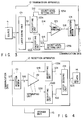
- FIG. 1 shows a first embodiment of a transmission apparatus according to the present invention.
- the transmission apparatus 12 of the embodiment carries out a coding process by dividing a video signal S1 from a source 11 into two layers.
- the transmission apparatus 12 is used as a server for pay TV broadcasting.
- the video signal S1 the contents of communication, from the external source 11 is supplied to a layer coding unit 121.
- the layer coding unit 121 divides the video signal S1 into two layers, encodes them, and outputs low-quality layer data S2 and high-quality layer data S3.
- An encrypting unit 122 encrypts the high-quality layer data S3 and outputs the encrypted high-quality layer data S4.
- a combining unit 123 combines the encrypted high-quality layer data S4 and the low-quality layer data S2 and outputs the synthesized data S5.
- a communication modem 124 converts the synthesized data S5 into data having communication characteristics suitable for a communication path (not shown) and outputs communication data S6.
- FIG. 2 shows a first embodiment of a reception apparatus according to the present invention.
- the reception apparatus 13 of the embodiment is used for a set top box in pay TV broadcasting.
- the communication data S6 transmitted via a communication path (not shown) is inputted to a reception modem 131.
- the reception modem 131 converts the transmitted data S6, which is the reverse of the conversion at the communication modem 124 in the transmission apparatus 12 and reproduces the synthesized data S7.
- a separating unit 132 separates the synthesized data S7 into encrypted high-quality layer data S8 and low-quality layer data S9.
- a decrypting unit 133 decrypts the encrypted high-quality layer data S8 and reproduces the high-quality layer data S10.
- the decrypting unit 133 If failing in decryption, such as when the key of the encrypted high-quality layer data S8 is wrong, the decrypting unit 133 outputs data that is against the layer coding grammar. When the ungrammatical data is inputted, a layer decoding unit 134 evaluates only the low-quality layer data S9 and reproduces the video signal S11.
- the video signal S11 from the layer decoding unit 134 is supplied to an external receiver 14, which displays images.
- the image of the high-quality layer data S3 cannot be viewed unless not only the layer decoding unit 134 but also the decrypting unit 133 are provided on the reception apparatus 13 side.
- a storage unit 15 stores and reproduces the synthesized data S7 from the reception modem 131.
- the recording medium may be magnetic tape or floppy disks, for example. Use of another storage unit enables the synthesized data S7 to be edited.
- a recording medium on which the synthesized data S7 has been recorded enables data exchange with a third party (i.e., a person under contract with the sender) having a reception apparatus of the same configuration as FIG. 2. If the reception apparatus of the third party has at least the layer decoding unit 134, the third party can view the images of low-quality layer data, but cannot view the high-quality layer data unless having the decrypting unit 133. Therefore, viewing cannot be done without permission and if copying is effected without permission, what has been copied will be useless, with the result that copying without permission can be prevented.
- a third party i.e., a person under contract with the sender
- the synthesized data S7 is reproduced from the storage unit 15 and is supplied to the separating unit 132.
- the data passes through the aforementioned processes and reaches the receiver 14, which displays images.
- the layer coding unit 121 may divide the video signal S1 into m layers and code the individual layers.
- the encrypting unit 122 may encrypt (m - 1) layer data items excluding the lowest-quality layer data item (the lowest resolution data item). Accordingly, the decrypting unit 133 decrypts the (m - 1) layer data items.
- the encrypting unit 122 may encrypt e high-quality layer data items. In this case, the decrypting unit 133 decrypts the e layer data items accordingly.
- FIG. 3 shows a second embodiment of the transmission apparatus according to the present invention. This embodiment performs a coding process by dividing the video signal from a source into two layers.
- the transmission apparatus 12 is used as a server for pay TV broadcasting.
- the video signal S1 the contents of communication, from the external source 11 is supplied to a layer coding unit 121.
- the layer coding unit 121 divides the video signal S1 into two layers, encodes them, and outputs low-quality layer data S2 and high-quality layer data S3.
- a secret level setting unit 125a generates a secret level setting signal S12 that sets the secret level of encryption of the low-quality layer data S2 and supplies it to an encrypting unit 122a.
- the encrypting unit 122a determines the secret level from the complexity of the encrypting scheme, the length of the encryption key, and the number of encryptions repeated, and encrypts the low-quality layer data S2.
- a secret level setting unit 125b generates a secret level setting signal S13 that sets the secret level of encryption of the high-quality layer data S3 and supplies it to an encrypting unit 122b.
- the secret level setting signal S13 sets a secret level higher than that of encryption of the low-quality layer data S2.
- the encrypting unit 122b determines the secret level from the complexity of the encrypting scheme, the length of the encryption key, and the number of encryptions repeated, and encrypts the high-quality layer data S3.
- a combining unit 123 combines the encrypted low-quality layer data S14 and high-quality layer data S15 and outputs the synthesized data S16.
- a communication modem 124 converts the synthesized data S16 into data having communication characteristics suitable for a communication path (not shown) and outputs communication data S17.
- a second embodiment of a reception apparatus of the present invention will be described by reference to FIG. 4.
- the reception apparatus 13 is used for a set top box in pay TV broadcasting.
- the communication data S17 transmitted from the transmission apparatus 12 via a communication path (not shown) is inputted to a reception modem 131.
- the reception modem 131 converts the transmitted data S17, which is the reverse of the conversion at the communication modem 124 and reproduces the synthesized data S18.
- a separating unit 132 separates the synthesized data S18 into encrypted low-quality layer data S19 and high-quality layer data S20.
- a decrypting unit 133a decrypts the encrypted low-quality layer data S19 and reproduces the low-quality layer data S21.
- a decrypting unit 133b decrypts the encrypted high-quality layer data S20 and reproduces the high-quality layer data S22.
- a layer decoding apparatus 134 decodes the low-quality layer data S21 and high-quality layer data S22 to reproduce a video signal S23.
- the decrypting unit 133b If failing in decryption, such as when the key of the encrypted high-quality layer data S20 is wrong, the decrypting unit 133b outputs data that is against the layer coding grammar. When the ungrammatical data is inputted, the layer decoding unit 134 evaluates only the low-quality layer data S21 and reproduces the video signal S1.
- the decrypting unit 133a outputs data that is against the layer coding grammar.
- the layer decoding unit 134 outputs a video signal S23 of a blue back screen corresponding to no input.
- the video signal S23 from the layer decoding unit 134 is supplied to an external receiver 14, which displays images or a blue back screen.
- the low-quality layer data S2 and high-quality layer data S3 are encrypted and then transmitted, the images cannot be viewed unless not only the layer decoding unit 134 but also the decrypting units 133a and 133b are provided on the reception apparatus side.
- a storage unit 15 stores and reproduces the synthesized data S18 from the reception modem 131.
- the recording medium may be magnetic tape or floppy disks, for example. Use of another storage unit enables the synthesized data S18 to be edited.
- a recording medium on which the synthesized data S18 has been recorded enables data exchange with a third party (i.e., a person under contract with the sender) having a reception apparatus of the same configuration as FIG. 4. If the reception apparatus of the third party has the decrypting unit 133a and the layer decoding unit 134, the third party can view at least the images of low-quality layer data. Therefore, viewing cannot be done without permission and if copying is effected without permission, what has been copied will be useless, with the result that copying without permission can be prevented.
- the synthesized data S18 is reproduced from the storage unit 15 and is supplied to the separating unit 132.
- the data passes through the aforementioned processes and reaches the receiver 14, which displays images.
- the layer coding unit 121 may divide the video signal S1 into m layers and code the individual layers. Then, a secret level setting unit and an encrypting unit are provided for each quality layer data item.
- the secrete level is the lowest for the lowest-quality layer data item (the lowest resolution data item), becomes higher as the quality gets higher, and is the highest for the highest-quality layer data item (the highest resolution data item). Accordingly, m decrypting units are provided in the reception apparatus.
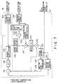
- FIG. 5 is a block diagram showing the overall configuration of a digital television broadcasting system according to the present invention.
- TR indicates a transmitter and RE indicates a receiver.
- a digital video signal (hereinafter, referred to as an HDTV signal) of the HDTV (High Definition TV) scheme is supplied to an input terminal 21.
- the signal is inputted to an HDTV compression layer encoder (hereinafter, just referred to as an HDTV encoder) 22.
- FIG. 6 illustrates a concrete configuration of the HDTV encoder 22.
- the configuration is a spatial layering model shown in ISO/IEC 13818-2.
- the inputted HDTV signal undergoes a 1/2 down sampling process at a down sampling circuit 221 and is sent to an SDTV (Standard Definition TV) compression layer encoder (hereinafter, just referred to an SDTV encoder) 23, which will be explained later.
- SDTV Standard Definition TV
- the down-sampled signal is also sent to a subtracter 223, which computes the difference between the input signal and the video signal of the preceding frame.
- the computation result undergoes DCT transform at a DCT circuit 224 and then the DCT-transformed signal is quantized at a quantization circuit 2225.
- the quantized video signal is subjected to variable-length coding at a variable-length coding circuit 2213 and the coded signal is sent to a packeting circuit 251 in an MPEG2 system layer circuit 25 explained later.
- the video signal quantized at the quantization circuit 225 is inverse-quantized at an inverse quantization circuit 2210 and is then subjected to inverse DCT transform at an inverse DCT circuit 2211. Thereafter, the converted signal is added to the video signal of the preceding frame. The addition result is delayed for one frame at a frame memory 229 and then is multiplied by a specific coefficient at a multiplier 228. The result is supplied to an adder 227.
- the video signal subjected to the compression process at the SDTV encoder 23 (hereinafter, referred to as an SDTV compression signal) is supplied to the HDTV encoder 22.
- the SDTV compressed signal is subjected to a twice up sampling process at an up sampling circuit 222 and then is multiplied by a specific coefficient at a multiplier 226.
- the result is supplied to the adder 227.
- the addition result from the adder 227 is sent as the video signal of the preceding frame to the subtracter 223 and the adder 2212.
- the coefficients given to the multipliers 226 and 228 are set so that they may total to 1 and the output of the subtracter 223 become the smallest. In this way, spatial layering is effected.
- FIG. 7 shows an SNR layering model determined in ISO/IEC 13818-2, which corresponds to the aforementioned SDTV encoder 23 and LDTV (Low Definition TV) compression layer encoder (hereinafter, just referred to as an LDTV encoder) 24.
- ISO/IEC 13818-2 corresponds to the aforementioned SDTV encoder 23 and LDTV (Low Definition TV) compression layer encoder (hereinafter, just referred to as an LDTV encoder) 24.
- the SDTV signal from the HDTV encoder 22 is inputted to a motion vector sensing circuit 231 of the SDTV encoder 23 and a subtracter 241 of the LDTV encoder 24.
- the motion vector sensing circuit 231 also receives the video signal delayed for one frame at a frame memory 232 to sense the motion vector and sends the sensed motion vector signal to a motion compensation circuit 233.
- the motion compensation circuit 233 simultaneously receives the one-frame-delayed video signal from the frame memory 232 and makes motion compensation according to the sensed motion vector signal.
- the motion-compensated video signal is sent via a switch circuit 234 to the subtracter 241 in the LDTV encoder 24.
- the switch circuit 234 is normally set in an on state. When the SDTV signal from the HDTV encoder 22 indicates intraframe coding, the switch circuit is brought into an off state.
- the subtracter 241 computes the difference between the present SDTV signal from the HDTV encoder 22 and the motion-compensated video signal of the preceding frame from the SDTV encoder 23 (in the case of intraframe coding, the present SDTV signal is outputted without any modification).
- the result is roughly quantized at a rough quantization circuit 243 and is variable-length-coded at a variable-length coding circuit 244, which outputs the coded signal as an LDTV compression signal to a packeting circuit 253 in the MPEG2 system layer circuit 25.
- the output of the rough quantization circuit 243 is also supplied to the SDTV encoder 23.
- a rough inverse quantization circuit 235 performs rough inverse quantization of the roughly quantized signal from the LDTV encoder 24 and supplies its output to a subtracter 236 and an adder 237.
- the subtracter 236 extracts only high-definition information by subtracting the roughly inverse-quantized signal from the rough inverse quantization circuit 235 from the present signal from the DCT 242 containing high-definition information before rough quantization.
- the thus obtained high-definition signal is quantized at a high-definition quantization circuit 238 and is variable-length coded at a variable-length coding circuit 239, which sends the coded signal as a SDTV compression signal to a packeting circuit 252 in the MPEG2 system layer circuit 25.
- the output of the high-definition quantization circuit 238 is inverse-quantized at a high-definition inverse quantization circuit 2310 and sent to an adder 237.
- the adder 237 adds the rough inverse quantization signal from the rough inverse quantization circuit 235 to the high-definition inverse quantization signal from the high-definition inverse quantization circuit 2310.
- the addition result is subjected to inverse DCT transform at an inverse DCT circuit 2311 and the result is inputted to an adder 2312.
- the adder 2312 adds the motion-compensated video signal of the preceding frame to the inverse DCT-transformed output, when the switch circuit 234 is on (when the video signal of the preceding frame is in a state other than intraframe coding).
- the addition output is inputted to the frame memory 232.
- the frame memory 232 delays the input video signal for one frame. As described earlier, the output of the frame memory 232 is supplied to the motion vector sensing circuit 231 and motion compensation circuit 233 as well as to the HDTV encoder 22.
- the outputs of the HDTV, SDTV, and LDTV encoders constructed as described above are packeted at the packeting circuits 251, 253, and 255 in the MPEG2 system layer circuit 25, respectively.
- Each of the packeting circuits 251, 253, and 255 assigns a packet ID (Identifier) to the packet signal to distinguish the signal from others.
- the scrambled signals are multiplexed in time at a multiplexing circuit (MPX) 256, which effects SNR (signal-to-noise ratio) layer coding of these signals.
- MPX multiplexing circuit
- the multiplexed output is supplied as an MPEG2 system layer processing output to an FEC (Forward Error Correction) encoder 26, which performs an FEC process on the supplied signal.
- FEC Forward Error Correction
- the receiver RE receives the transmission signal from the transmitter TR
- the received signal is demodulated at a modulation circuit 31.
- the modulated signal undergoes an FEC decode process at an FEC decoder 32.
- the resulting signal is inputted to an MPEG2 system layer circuit 33.
- a demultiplexing circuit (DEMAX) 331 demultiplexes the inputted time-division multiplexing signal on the basis of the packet IDs assigned at the transmission side.
- DEMAX demultiplexing circuit
- HDTV compression signal and SDTV compression signal are sent via switch circuits 34 and 35 to an HDTV compression layer decoder (hereinafter, just referred to as an HDTV decoder) 36 and an SDTV compression layer decoder (hereinafter, just referred to as an SDTV decoder) 37, respectively.
- an HDTV compression layer decoder hereinafter, just referred to as an HDTV decoder
- an SDTV compression layer decoder hereinafter, just referred to as an SDTV decoder
- the switch circuits 34 and 35 are turned on, only when the reception of the HDTV signal and SDTV signal is permitted.
- the LDTV packet signal (the SNR-layer-coded low-band signal (the high layer signal in space layering)) is inputted directly to a depacketing circuit 336, which performs a depacketing process on the LDTV compression signal.
- the LDTV compression signal is sent to an LDTV compression layer decoder (hereinafter, just referred to as an LDTV decoder) 38.
- FIGS. 8 and 9 show a concrete configuration of the decoder of each layer.
- FIG. 8 shows a concrete configuration of the portion corresponding to the LDTV decoder 38 and SDTV decoder 37 of FIG. 5. Referring to FIG. 8, SNR layer decoding will be explained.
- the LDTV compression signal (the low-band component of the space layering signal) from the depacketing circuit 336 is inputted to a variable-length decoding circuit 381, which decodes the input.
- the decoded signal is supplied to a rough inverse quantization circuit 382, which performs rough inverse quantization.
- the output of the inverse quantization circuit 382 is inputted to an inverse DCT circuit 383 as well as to an adder 373 of the SDTV decoder 37.
- the inverse DCT circuit 383 performs inverse DCT transform according to the coefficient obtained from inverse quantization.
- the output of the transform is added to the signal of the preceding frame at an adder 384, which thereby restores it to the original LDTV signal.
- the LDTV signal is inputted to a frame memory 386, which performs a one-frame delay process.
- the output of the frame memory 386 is subjected to motion compensation at a motion compensation circuit 387 according to a motion compensation signal (not shown).
- the compensated signal is inputted via a switch circuit 385 to the adder 384.
- the switch circuit 385 is normally set in an on state. When the output signal from the inverse DCT circuit 383 is a intraframe coding signal, the switch circuit is brought into an off state to prevent the signal from the motion compensation circuit 387 from being supplied to the adder 384.
- the LDTV signal decoded as described above is outputted from the adder 384 to an LDTV display unit 41.
- a horizontal pixel curtailing circuit performs a pixel curtailing process on the LDTV signal
- a vertical line curtailing circuit performs a line curtailing process on the LDTV signal. Then, the unnecessary horizontal and vertical high-band components are eliminated by a horizontal and vertical filters and thereafter, representation with SIF resolution (about half of the horizontal and vertical of R601) is allowed to appear on the display.
- the SDTV compression signal (the high-band component of the space layering signal) obtained at a depacketing circuit 335 is inputted to the SDTV decoder 37.
- a high-definition inverse quantization circuit 372 performs an inverse quantization process on the decoded signal.
- the resulting signal is inputted to an adder 373, which adds it to the rough quantization signal obtained at the LDTV decoder 38.
- the output of the adder 373 contains only the output of the rough inverse quantization circuit 382 and makes a signal containing only the low-band components.
- the output of the adder 373 thus obtained is subjected to inverse DCT transform at an inverse DCT circuit 374 and then the transformed signal is added to the signal of the preceding frame at an adder 375, which thereby restores it to the original SDTV signal.
- the SDTV signal is inputted to a frame memory 377, which performs an one-frame delay process.
- the output of the frame memory 377 undergoes motion compensation at a motion compensation circuit 378 according to a motion compensation signal (not shown).
- the compensated signal is inputted via a switch circuit 376 to an adder 374.
- the switch circuit 376 is normally set in an on state. When the output signal from the inverse DCT circuit 383 is a intraframe coding signal, the switch circuit is brought into an off state to prevent the signal from the motion compensation circuit 378 from being supplied to the adder 376.
- the SDTV signal decoded as described above is outputted from the adder 375 to an SDTV display unit 40, which provides representation of R601 level.
- an SDTV display unit 40 which provides representation of R601 level.
- the output of the frame memory 377 is outputted to the HDTV decoder 36.
- descrambling is not permitted, only the low-band signal in SNR layering is outputted to the HDTV decoder 36.
- the HDTV compression signal (the high-band component of the space layering signal) obtained at a depacketing circuit 333 is inputted to the HDTV decoder 36 and is decoded at a variable-length decoding circuit 361.
- the decoded signal undergoes an inverse quantization process at an inverse quantization circuit 363 and is subjected to an inverse DCT process at an inverse DCT circuit 364. Thereafter, the resulting signal is inputted to an adder 365, which adds it to the video signal of the preceding frame inputted via a switch circuit 366.
- the video signal of the preceding frame is obtained as follows.
- the signal sent from the frame memory 377 in the SDTV decoder 37 is subjected to a twice up sampling process at an up sample circuit 362.
- the up sampled signal is multiplied by a coefficient sent from the transmission side at a multiplier 367.
- the output of the adder 365 is delayed for one frame at a frame memory 368.
- the delayed output is subjected to motion compensation at a motion compensation circuit 369 on the basis of the motion vector signal sent from the transmission side.
- the compensated signal is multiplied by a coefficient sent from the transmission side at a multiplier 3610.
- the video signal of the preceding frame is produced by adding the output of the multiplier 367 to that of the multiplier 3610.
- the switch circuit 366 is normally set in an on state. When the output signal from the inverse DCT circuit 364 is a intraframe coding signal, the switch circuit is brought into an off state to cut off the supply of the signal to the adder 365.
- the HDTV signal thus obtained (the signal about twice the horizontal and vertical of R601) is outputted to an HDTV display unit 39, which displays the signal.
- the resolution of the HDTV display unit 39 is on the order of R601 at best.
- the resolution of the HDTV display unit 39 is on the order of SIF (the resolution about half of the horizontal and vertical of R601).
- the high layer encode signals (HDTV, SDTV) are scrambled and the low layer encode signals (LDTV) are not scrambled.
- a descrambling process is selectively performed in a high layer signal decoding process to enable the signals to be displayed, whereas in a low layer signal decoding process, the signals can be displayed without a descrambling process.
- a layer called a system layer is provided as a layer for multiplexing the compression layers.
- a charging flag is provided for the system layer. Scrambling can be controlled by using the flag. When this approach is used directly, however, reproduction of the scrambled signal will cause totally illegible images to appear on the screen.
- normal images are allowed to be reproduced from the low layer data and be displayed on the reception side by a method that scrambles only the high layers of layered images and does not scramble the low layers in the system layer protocol.
- the images actually have no bandwidth and are barely understandable.
- an HDTV display unit 39 for which the descrambling of the high layer signals in space layering and the high layer signals in SNR layering has not been permitted (under no contract with the sender for fees), only the images whose contents are barely understandable and which has a very low resolution, can be recognized free of charge.
- images with a resolution of the order of R601 will be obtained.
- the video signal of each level can be displayed.
- a screen that is not scrambled can be displayed in the size about 1/16 of the HDTV screen as shown in FIG. 10A.
- a screen that is of the size about 1/4 of the HDTV screen and has a resolution of the order of R601 can be displayed as shown in FIG. 10B.
- a picture equivalent to LCTV can be enlarged and displayed on the HDTV entire screen (is allowed to fill the entire screen).
- a picture equivalent to LCTV can be enlarged and displayed on the SDTV entire screen (is allowed to fill the entire screen).
- a picture equivalent to SDTV can be enlarged and displayed on the HDTV entire screen (is allowed to fill the entire screen).
- the layer coding process on the transmitter TR side is not limited to those in the above embodiments, but may be achieved in other methods.
- the layer data set by the sender can be viewed and listened to by only the privileged viewers under contract with the sender, which helps protect copyrights. Additionally, the receivers can record, edit, and exchange the contents of communications with a third party.
Abstract
Video signals are enciphered so that only entitled persons can watch the program sent by the video signals. A layer encoder (5) encodes video signals (3) by dividing the signals (3) into two layers. An enciphering device (65) enciphers low-definition layer data (57) in accordance with a setting signal (63) from a degree-of-secrecy setting device (61) and supplies the enciphered data to a combining device (77). Another enciphering device (73) enciphers high-definition layer data (59) in accordance with a setting signal (71) from another degree-of-secrecy setting device (69) and supplies the enciphered data to the combining device (77). The device (73) enciphers the data at a higher degree-of-secrecy than that of the device (65). Composite data (79) from the combining device (77) are converted into communication data (83) by means of a communication MODEM (81) and transmitted to a receiver.
Description
- The present invention relates to a transmission apparatus and a reception apparatus that are useful for pay TV broadcasting for which viewers have to pay TV license fees or for protection of copyrights, for example, and a communication processing system that integrates these apparatuses.
- Furthermore, the present invention relates to a digital television broadcasting system which is an example of the communication processing system and which performs a scrambling process on digital television signals and broadcast them, and more particularly to pay broadcasting techniques.
- Recently, communication processing systems where viewers make a contract with the sender and only the receivers given the special right are allowed to watch the programs, have been demanded from the points of view of pay TV systems that charge the viewers TV licence fees as well as protection of copyrights.
- Accordingly, an object of the present invention is to provide a transmission system and a reception system that permit only the privileged viewers under contract with the sender for reception of pay TV broadcasting to watch the programs, and a communication processing system that integrates these apparatuses.
- Another object of the present invention is to provide a transmission system and a reception system that are capable of recording, editing, and exchanging the contents of communications with a third party, and a communication processing system that integrates these apparatuses.
- In recent years, as video and audio digital signal processing technology have made a remarkable progress, more and more research effort has been directed worldwide toward systems that realize digital television broadcasting and the fusion of broadcasting and communication. In this movement, one of the most important techniques is video and audio compression techniques.
- Major compression techniques are MPEG, JPEG, and H.261. The schemes proposed by ISO/IEC 1318-1 (Moving Picture Experts Group (ISO/IECJTC1/SC29/WG11)) are now under examination for worldwide standardization of broadcasting, communications, and storage media.
- ISO/IEC 13818-1 has determined not only an image compression scheme but also a scheme for a section where the transmission side compresses the video and audio data items of programs separately, generates and multiplexes the bit streams, and broadcasts the multiplexed signal, and a scheme for a control section that enables reception of a specified program on the reception side.
- With the advances in the digital signal processing techniques, pay digital television broadcasting has been examined. The most important problem is charging techniques.
- As a conventional technique for dealing with this problem, a scrambling scheme has been proposed which is characterized by generating random numbers without changing the code length in a compression layer complying with the MPEG standard. Since MPEG uses variable-length quantization techniques, however, it is very difficult to effect scrambling without changing the code length.
- With this backdrop, Matsushita's Image Laboratory has proposed a scheme at a meeting of the Electronic Data Communication Society of Japan in December, 1992. The scheme is such that the entire quantization scale or the entire fixed-length code of the DCT direct-current component is multiplied by PN, whereas for a motion vector or a variable-length code of the DCT alternating-current component, the codes in the code book are multiplied by PN.
- With this scheme, when the compression-decoded images without descrambling are viewed, the contents of the images can hardly be understood, so that pay broadcasting can be realized by delivering descrambling units to the subscribers who have paid charges.
- This scheme, however, has a disadvantages in that encoding and decoding are very difficult. Additionally, because the contents of programs cannot be understood, it is difficult to let viewers other than the subscribers know the good points of the contents of programs.
- If the resolution can be lowered to the extent that the contents of a program can be understood, it is possible to allow the program to appeal to would-be subscribers and motivate them to subscribe to the service. The above scheme with which would-be subscribers cannot recognize the contents of programs, however, can be considered to be unsuitable for practical broadcasting service.
- As described above, in a digital television broadcasting system, with the conventional scramble broadcasting scheme, not only are encoding and decoding very difficult, but also the contents of programs can hardly be understood when the compression-decoded images are viewed without descrambling in the case of pay TV service. As a result, it is difficult to appeal to would-be subscribers and therefore, they are not motivated to subscribe to the service.
- Accordingly, an object of the present invention is to provide as an example of the communication processing system a digital television broadcasting system as an example of the communication processing system which, even when a scrambled program is selected and decoded without descrambling, enables the program to be viewed to the extent that the contents of the program can be understood.
- A first transmission apparatus according to the present invention comprises: layer coding means for dividing data into m (m is an integer not less than 2) layers and coding each layer; encrypting means for encrypting (m - 1) layer data items from the layer coding means excluding the lowest-quality layer data item; and combining means for combining the lowest-quality layer data item from the layer coding means and the encrypted (m - 1) layer data items from the encrypting means.
- A first reception apparatus according to the present invention comprises: separating means that receives the synthesized data obtained by dividing data into m (m is an integer not less than 2) layers, coding each layer, encrypting (m - 1) layer data items excluding the lowest-quality layer data item, and combining the lowest-quality layer data item and the (m - 1) encrypted layer data items, and that separates the synthesized data into (m - 1) encrypted layer data items and the lowest-quality layer data item; decrypting means for decrypting the (m - 1) encrypted layer data items from the separating means; and layer decoding means for decoding the (m - 1) layer data items from the decrypting means and the lowest-quality layer data item from the separating means.
- A first communication processing system according to the present invention comprises: a transmission apparatus comprising: layer coding means for dividing data into m (m is an integer not less than 2) layers and coding each layer; encrypting means for encrypting (m - 1) layer data items from the layer coding means excluding the lowest-quality layer data item; and combining means for combining the lowest-quality layer data item from the layer coding means and the (m - 1) encrypted layer data items from the encrypting means; and a reception apparatus comprising: separating means for separating the synthesized data created at the combining means into (m - 1) encrypted layer data items and the lowest-quality layer data item; decrypting means for decrypting the (m - 1) encrypted layer data items from the separating means; and layer decoding means for decoding the (m - 1) layer data items from the decrypting means and the lowest-quality layer data item from the separating means.
- A second transmission apparatus according to the present invention comprises: layer coding means for dividing data into m (m is an integer not less than 2) layers and coding each layer; encrypting means for encrypting e (e is an integer not less than 2) high-quality layer data items from the layer coding means; and combining means for combining (m - e) low-quality layer data items from the layer coding means and the e encrypted layer data items from the encrypting means.
- A second reception apparatus according to the present invention comprises: separating means that receives the synthesized data obtained by dividing data into m (m is an integer not less than 2) layers, coding each layer, encrypting e (e is an integer not less than 2) high-quality layer data items, and combining the remaining (m - e) low-quality layer data items and the e encrypted layer data items, and that separates the synthesized data into e encrypted layer data items and (m - e) low-quality layer data items; decrypting means for decrypting the e encrypted layer data items from the separating means; and layer decoding means for decoding the e layer data items from the decrypting means and the (m - e) low-quality layer data items from the separating means.
- A second communication processing system according to the present invention comprises: a transmission apparatus comprising: layer coding means for dividing data into m (m is an integer not less than 2) layers and coding each layer; encrypting means for encrypting e (e is an integer not less than 2) high-quality layer data items from the layer coding means; and combining means for combining (m - e) low-quality layer data items from the layer coding means and the e encrypted layer data items from the encrypting means; and a reception apparatus comprising separating means for separating the synthesized data created at the combining means into e encrypted layer data items and (m - e) low-quality layer data items; decrypting means for decrypting the e encrypted layer data items from the separating means; and layer decoding means for decoding the e layer data items from the decrypting means and the (m - e) low-quality layer data items from the separating means.
- With the first transmission apparatus or the transmission apparatus of the first communication system constructed as described above, for example, the layer coding means divides video signals into two layers and codes each layer. After the high-quality ones of the layer data items have been encrypted, the encrypted data items are combined with the low-quality layer data items. Then, the resulting signal is transmitted to the reception apparatus side.
- With the first reception apparatus or the reception apparatus of the first communication system constructed as described above, the received synthesized data is separated into the encrypted high-quality layer data items and the low-quality layer data items and the encrypted high-quality layer data items are decrypted. The decrypted high-quality layer data items and the low-quality layer data items are decoded by layer.
- Because the high-quality layer data items are encrypted, they can be viewed by only the privileged viewers having the proper decrypting means.
- By further providing storage means on the reception apparatus side, the received synthesized data can be recorded or edited. Use of the storage means enables data exchange of the low-quality layer data items with a third party other than the privileged viewers. For the high-quality layer data items, the storage means enables data exchange of these items plus the low-quality layer data items with only the privileged viewers.
- With the second transmission apparatus or the transmission apparatus of the second communication system constructed as described above, for example, the layer coding means divides video signals into two layers and codes each layer. The low-quality layer data items and the high-quality layer data items are encrypted at different secret levels. These encrypted low-quality layer data items and high-quality layer data items are decrypted. The decrypted signal is transmitted to the reception apparatus side.
- With the second reception apparatus or the reception apparatus of the second communication system constructed as described above, the received synthesized data is separated into the encrypted low-quality layer data items and high-quality layer data items and these layer data items are decrypted separately. The decrypted low-quality layer data items and high-quality layer data items are decoded by layer.
- Since the both of the low-quality layer data items and high-quality layer data items are encrypted at different secret levels, they can be viewed by only the privileged viewers having the proper decrypting means.
- By further providing storage means on the reception apparatus side, the received synthesized data can be recorded or edited. Use of the storage means enables data exchange with only the privileged viewers.
- A digital television broadcasting system of the present invention is a system that converts digital television signals into a plurality of encode signals differing in resolution, layers these signals, and broadcasts them, and is characterized by comprising: scrambling means that is provided on the transmission side and performs a scrambling process on only the high layer ones of the plurality of encode signals; and descrambling means that is provided on the reception side and performs a descrambling process on the encode signals subjected to the high layer scrambling process, wherein for the high layer encode signals, the output of the descrambling means undergoes a decoding process, whereas for the low layer encode signals, the decoding process is performed without the descrambling process.
- With the digital television broadcasting system, because only the high layer ones of the layered encode signals are subjected to the scrambling process and then broadcasted, the broadcasting service of the high layer encode signals cannot be received on the reception side unless the high layer encode signals are subjected to the descrambling process. Since the low layer encode signals have not been scrambled, the decoding of these signals enables viewers to view them, allowing the viewer to understand the contents of the programs.
-
- FIG. 1 is a block diagram of a first embodiment of a transmission apparatus according to the present invention;
- FIG. 2 is a block diagram of a first embodiment of a reception apparatus according to the present invention;
- FIG. 3 is a block diagram of a second embodiment of the transmission apparatus according to the present invention;
- FIG. 4 is a block diagram of a second embodiment of the reception apparatus according to the present invention;
- FIG. 5 is a circuit block diagram of a first embodiment of a digital television broadcasting system according to the present invention;
- FIG. 6 is a circuit block diagram showing a concrete configuration of an HDTV compression layer encoder that performs a spatial layering process in the embodiment of FIG. 5;
- FIG. 7 is a block diagram showing a concrete configuration of an SDTV and LDTV compression layer encoder that performs an SNR layering process in the embodiment of FIG. 5;
- FIG. 8 is a block diagram showing a concrete configuration of an SDTV and LDTV compression layer decoder that performs an SNR layering process in the embodiment of FIG. 5;
- FIG. 9 is a block diagram showing a concrete configuration of an HDTV compression layer decoder that performs a spatial layering process in the embodiment of FIG. 5; and
- FIGS. 10A to 10D each illustrate an example of display in the embodiment of FIG. 5.
- Hereinafter, referring to the accompanying drawings, embodiments of the present invention will be explained in detail.
- FIG. 1 shows a first embodiment of a transmission apparatus according to the present invention.
- The transmission apparatus 12 of the embodiment carries out a coding process by dividing a video signal S1 from a source 11 into two layers.
- Specifically, the transmission apparatus 12 is used as a server for pay TV broadcasting. The video signal S1, the contents of communication, from the external source 11 is supplied to a
layer coding unit 121. Thelayer coding unit 121 divides the video signal S1 into two layers, encodes them, and outputs low-quality layer data S2 and high-quality layer data S3. - An
encrypting unit 122 encrypts the high-quality layer data S3 and outputs the encrypted high-quality layer data S4. A combiningunit 123 combines the encrypted high-quality layer data S4 and the low-quality layer data S2 and outputs the synthesized data S5. Acommunication modem 124 converts the synthesized data S5 into data having communication characteristics suitable for a communication path (not shown) and outputs communication data S6. - FIG. 2 shows a first embodiment of a reception apparatus according to the present invention. The reception apparatus 13 of the embodiment is used for a set top box in pay TV broadcasting. The communication data S6 transmitted via a communication path (not shown) is inputted to a
reception modem 131. Thereception modem 131 converts the transmitted data S6, which is the reverse of the conversion at thecommunication modem 124 in the transmission apparatus 12 and reproduces the synthesized data S7. - A separating
unit 132 separates the synthesized data S7 into encrypted high-quality layer data S8 and low-quality layer data S9. A decryptingunit 133 decrypts the encrypted high-quality layer data S8 and reproduces the high-quality layer data S10. - If failing in decryption, such as when the key of the encrypted high-quality layer data S8 is wrong, the decrypting
unit 133 outputs data that is against the layer coding grammar. When the ungrammatical data is inputted, alayer decoding unit 134 evaluates only the low-quality layer data S9 and reproduces the video signal S11. - The video signal S11 from the
layer decoding unit 134 is supplied to anexternal receiver 14, which displays images. - With the above configuration, as described above, because the high-quality layer data S3 is encrypted and then transmitted, the image of the high-quality layer data S3 cannot be viewed unless not only the
layer decoding unit 134 but also thedecrypting unit 133 are provided on the reception apparatus 13 side. - Furthermore, a
storage unit 15 stores and reproduces the synthesized data S7 from thereception modem 131. The recording medium may be magnetic tape or floppy disks, for example. Use of another storage unit enables the synthesized data S7 to be edited. - Use of a recording medium on which the synthesized data S7 has been recorded enables data exchange with a third party (i.e., a person under contract with the sender) having a reception apparatus of the same configuration as FIG. 2. If the reception apparatus of the third party has at least the
layer decoding unit 134, the third party can view the images of low-quality layer data, but cannot view the high-quality layer data unless having the decryptingunit 133. Therefore, viewing cannot be done without permission and if copying is effected without permission, what has been copied will be useless, with the result that copying without permission can be prevented. - Additionally, when the image of the synthesized data S7 recorded or that of the synthesized data S7 received from a third party is reproduced, the synthesized data S7 is reproduced from the
storage unit 15 and is supplied to theseparating unit 132. The data passes through the aforementioned processes and reaches thereceiver 14, which displays images. - While in the embodiment, an example of coding in two layers has been explained, the
layer coding unit 121 may divide the video signal S1 into m layers and code the individual layers. At this time, the encryptingunit 122 may encrypt (m - 1) layer data items excluding the lowest-quality layer data item (the lowest resolution data item). Accordingly, the decryptingunit 133 decrypts the (m - 1) layer data items. The encryptingunit 122 may encrypt e high-quality layer data items. In this case, the decryptingunit 133 decrypts the e layer data items accordingly. - FIG. 3 shows a second embodiment of the transmission apparatus according to the present invention. This embodiment performs a coding process by dividing the video signal from a source into two layers.
- The transmission apparatus 12 is used as a server for pay TV broadcasting. The video signal S1, the contents of communication, from the external source 11 is supplied to a
layer coding unit 121. Thelayer coding unit 121 divides the video signal S1 into two layers, encodes them, and outputs low-quality layer data S2 and high-quality layer data S3. - A secret level setting unit 125a generates a secret level setting signal S12 that sets the secret level of encryption of the low-quality layer data S2 and supplies it to an encrypting unit 122a. Receiving the secret level setting signal S12, the encrypting unit 122a determines the secret level from the complexity of the encrypting scheme, the length of the encryption key, and the number of encryptions repeated, and encrypts the low-quality layer data S2.
- A secret
level setting unit 125b generates a secret level setting signal S13 that sets the secret level of encryption of the high-quality layer data S3 and supplies it to anencrypting unit 122b. The secret level setting signal S13 sets a secret level higher than that of encryption of the low-quality layer data S2. Receiving the secret level setting signal S13, the encryptingunit 122b determines the secret level from the complexity of the encrypting scheme, the length of the encryption key, and the number of encryptions repeated, and encrypts the high-quality layer data S3. - A combining
unit 123 combines the encrypted low-quality layer data S14 and high-quality layer data S15 and outputs the synthesized data S16. Acommunication modem 124 converts the synthesized data S16 into data having communication characteristics suitable for a communication path (not shown) and outputs communication data S17. - A second embodiment of a reception apparatus of the present invention will be described by reference to FIG. 4. The reception apparatus 13 is used for a set top box in pay TV broadcasting. The communication data S17 transmitted from the transmission apparatus 12 via a communication path (not shown) is inputted to a
reception modem 131. Thereception modem 131 converts the transmitted data S17, which is the reverse of the conversion at thecommunication modem 124 and reproduces the synthesized data S18. - A separating
unit 132 separates the synthesized data S18 into encrypted low-quality layer data S19 and high-quality layer data S20. A decrypting unit 133a decrypts the encrypted low-quality layer data S19 and reproduces the low-quality layer data S21. A decrypting unit 133b decrypts the encrypted high-quality layer data S20 and reproduces the high-quality layer data S22. - A
layer decoding apparatus 134 decodes the low-quality layer data S21 and high-quality layer data S22 to reproduce a video signal S23. - If failing in decryption, such as when the key of the encrypted high-quality layer data S20 is wrong, the decrypting unit 133b outputs data that is against the layer coding grammar. When the ungrammatical data is inputted, the
layer decoding unit 134 evaluates only the low-quality layer data S21 and reproduces the video signal S1. - Additionally, if failing in decryption, such as when the key of the encrypted low-quality layer data S14 is wrong, the decrypting unit 133a outputs data that is against the layer coding grammar. When the ungrammatical data is inputted, the
layer decoding unit 134 outputs a video signal S23 of a blue back screen corresponding to no input. - The video signal S23 from the
layer decoding unit 134 is supplied to anexternal receiver 14, which displays images or a blue back screen. - As described above, because the low-quality layer data S2 and high-quality layer data S3 are encrypted and then transmitted, the images cannot be viewed unless not only the
layer decoding unit 134 but also the decrypting units 133a and 133b are provided on the reception apparatus side. - Furthermore, a
storage unit 15 stores and reproduces the synthesized data S18 from thereception modem 131. The recording medium may be magnetic tape or floppy disks, for example. Use of another storage unit enables the synthesized data S18 to be edited. - Use of a recording medium on which the synthesized data S18 has been recorded enables data exchange with a third party (i.e., a person under contract with the sender) having a reception apparatus of the same configuration as FIG. 4. If the reception apparatus of the third party has the decrypting unit 133a and the
layer decoding unit 134, the third party can view at least the images of low-quality layer data. Therefore, viewing cannot be done without permission and if copying is effected without permission, what has been copied will be useless, with the result that copying without permission can be prevented. - Additionally, when the image of the synthesized data S18 recorded or that of the synthesized data S18 received from a third party is reproduced, the synthesized data S18 is reproduced from the
storage unit 15 and is supplied to theseparating unit 132. The data passes through the aforementioned processes and reaches thereceiver 14, which displays images. - While in the embodiment, an example of coding in two layers has been explained, the
layer coding unit 121 may divide the video signal S1 into m layers and code the individual layers. Then, a secret level setting unit and an encrypting unit are provided for each quality layer data item. The secrete level is the lowest for the lowest-quality layer data item (the lowest resolution data item), becomes higher as the quality gets higher, and is the highest for the highest-quality layer data item (the highest resolution data item). Accordingly, m decrypting units are provided in the reception apparatus. - FIG. 5 is a block diagram showing the overall configuration of a digital television broadcasting system according to the present invention. In the figure, TR indicates a transmitter and RE indicates a receiver.
- In the transmitter RT, a digital video signal (hereinafter, referred to as an HDTV signal) of the HDTV (High Definition TV) scheme is supplied to an
input terminal 21. The signal is inputted to an HDTV compression layer encoder (hereinafter, just referred to as an HDTV encoder) 22. - FIG. 6 illustrates a concrete configuration of the
HDTV encoder 22. The configuration is a spatial layering model shown in ISO/IEC 13818-2. - The inputted HDTV signal undergoes a 1/2 down sampling process at a
down sampling circuit 221 and is sent to an SDTV (Standard Definition TV) compression layer encoder (hereinafter, just referred to an SDTV encoder) 23, which will be explained later. The down-sampled signal is also sent to asubtracter 223, which computes the difference between the input signal and the video signal of the preceding frame. The computation result undergoes DCT transform at aDCT circuit 224 and then the DCT-transformed signal is quantized at a quantization circuit 2225. The quantized video signal is subjected to variable-length coding at a variable-length coding circuit 2213 and the coded signal is sent to apacketing circuit 251 in an MPEG2system layer circuit 25 explained later. - The video signal quantized at the
quantization circuit 225 is inverse-quantized at aninverse quantization circuit 2210 and is then subjected to inverse DCT transform at aninverse DCT circuit 2211. Thereafter, the converted signal is added to the video signal of the preceding frame. The addition result is delayed for one frame at aframe memory 229 and then is multiplied by a specific coefficient at amultiplier 228. The result is supplied to anadder 227. - On the other hand, the video signal subjected to the compression process at the SDTV encoder 23 (hereinafter, referred to as an SDTV compression signal) is supplied to the
HDTV encoder 22. The SDTV compressed signal is subjected to a twice up sampling process at an upsampling circuit 222 and then is multiplied by a specific coefficient at amultiplier 226. The result is supplied to theadder 227. The addition result from theadder 227 is sent as the video signal of the preceding frame to thesubtracter 223 and theadder 2212. - The coefficients given to the
multipliers subtracter 223 become the smallest. In this way, spatial layering is effected. - Next, low level layers will be explained by reference to FIG. 7. FIG. 7 shows an SNR layering model determined in ISO/IEC 13818-2, which corresponds to the
aforementioned SDTV encoder 23 and LDTV (Low Definition TV) compression layer encoder (hereinafter, just referred to as an LDTV encoder) 24. - In FIG. 7, the SDTV signal from the
HDTV encoder 22 is inputted to a motionvector sensing circuit 231 of theSDTV encoder 23 and asubtracter 241 of theLDTV encoder 24. - In the
SDTV encoder 23, the motionvector sensing circuit 231 also receives the video signal delayed for one frame at aframe memory 232 to sense the motion vector and sends the sensed motion vector signal to amotion compensation circuit 233. Themotion compensation circuit 233 simultaneously receives the one-frame-delayed video signal from theframe memory 232 and makes motion compensation according to the sensed motion vector signal. - The motion-compensated video signal is sent via a
switch circuit 234 to thesubtracter 241 in theLDTV encoder 24. Theswitch circuit 234 is normally set in an on state. When the SDTV signal from theHDTV encoder 22 indicates intraframe coding, the switch circuit is brought into an off state. - In the
LDTV encoder 24, thesubtracter 241 computes the difference between the present SDTV signal from theHDTV encoder 22 and the motion-compensated video signal of the preceding frame from the SDTV encoder 23 (in the case of intraframe coding, the present SDTV signal is outputted without any modification). - After the difference value has undergone DCT transform at a
DCT circuit 242, the result is roughly quantized at arough quantization circuit 243 and is variable-length-coded at a variable-length coding circuit 244, which outputs the coded signal as an LDTV compression signal to apacketing circuit 253 in the MPEG2system layer circuit 25. The output of therough quantization circuit 243 is also supplied to theSDTV encoder 23. - In the
SDTV encoder 23, a roughinverse quantization circuit 235 performs rough inverse quantization of the roughly quantized signal from theLDTV encoder 24 and supplies its output to asubtracter 236 and anadder 237. - The
subtracter 236 extracts only high-definition information by subtracting the roughly inverse-quantized signal from the roughinverse quantization circuit 235 from the present signal from theDCT 242 containing high-definition information before rough quantization. The thus obtained high-definition signal is quantized at a high-definition quantization circuit 238 and is variable-length coded at a variable-length coding circuit 239, which sends the coded signal as a SDTV compression signal to apacketing circuit 252 in the MPEG2system layer circuit 25. - The output of the high-
definition quantization circuit 238 is inverse-quantized at a high-definitioninverse quantization circuit 2310 and sent to anadder 237. Theadder 237 adds the rough inverse quantization signal from the roughinverse quantization circuit 235 to the high-definition inverse quantization signal from the high-definitioninverse quantization circuit 2310. The addition result is subjected to inverse DCT transform at aninverse DCT circuit 2311 and the result is inputted to anadder 2312. - The
adder 2312 adds the motion-compensated video signal of the preceding frame to the inverse DCT-transformed output, when theswitch circuit 234 is on (when the video signal of the preceding frame is in a state other than intraframe coding). The addition output is inputted to theframe memory 232. Theframe memory 232 delays the input video signal for one frame. As described earlier, the output of theframe memory 232 is supplied to the motionvector sensing circuit 231 andmotion compensation circuit 233 as well as to theHDTV encoder 22. - The outputs of the HDTV, SDTV, and LDTV encoders constructed as described above are packeted at the
packeting circuits system layer circuit 25, respectively. Each of thepacketing circuits - After the HDTV packet signal and SDTV packet signal from the packeting
circuits circuits packeting circuit 255, are multiplexed in time at a multiplexing circuit (MPX) 256, which effects SNR (signal-to-noise ratio) layer coding of these signals. The multiplexed output is supplied as an MPEG2 system layer processing output to an FEC (Forward Error Correction)encoder 26, which performs an FEC process on the supplied signal. The resulting signal is supplied to amodulator 27, which modulates the signal and produces the broadcasting output. - Then, when the receiver RE receives the transmission signal from the transmitter TR, the received signal is demodulated at a
modulation circuit 31. The modulated signal undergoes an FEC decode process at anFEC decoder 32. The resulting signal is inputted to an MPEG2system layer circuit 33. - In the MPEG2
system layer circuit 33, a demultiplexing circuit (DEMAX) 331 demultiplexes the inputted time-division multiplexing signal on the basis of the packet IDs assigned at the transmission side. After the HDTV packet signal and SDTV packet signal separated here (the high-band signals subjected to SNR layer coding (the low-level layer signals in space layering)) have been descrambled at descramblingcircuits depacketing circuit 333. These HDTV compression signal and SDTV compression signal are sent viaswitch circuits - The
switch circuits - The LDTV packet signal (the SNR-layer-coded low-band signal (the high layer signal in space layering)) is inputted directly to a
depacketing circuit 336, which performs a depacketing process on the LDTV compression signal. The LDTV compression signal is sent to an LDTV compression layer decoder (hereinafter, just referred to as an LDTV decoder) 38. - The compression signals of the individual layers thus obtained are inputted to the
decoders - FIG. 8 shows a concrete configuration of the portion corresponding to the
LDTV decoder 38 andSDTV decoder 37 of FIG. 5. Referring to FIG. 8, SNR layer decoding will be explained. - In the
LDTV decoder 38, the LDTV compression signal (the low-band component of the space layering signal) from thedepacketing circuit 336 is inputted to a variable-length decoding circuit 381, which decodes the input. The decoded signal is supplied to a roughinverse quantization circuit 382, which performs rough inverse quantization. The output of theinverse quantization circuit 382 is inputted to aninverse DCT circuit 383 as well as to anadder 373 of theSDTV decoder 37. - The
inverse DCT circuit 383 performs inverse DCT transform according to the coefficient obtained from inverse quantization. The output of the transform is added to the signal of the preceding frame at anadder 384, which thereby restores it to the original LDTV signal. The LDTV signal is inputted to aframe memory 386, which performs a one-frame delay process. The output of theframe memory 386 is subjected to motion compensation at amotion compensation circuit 387 according to a motion compensation signal (not shown). The compensated signal is inputted via aswitch circuit 385 to theadder 384. - The
switch circuit 385 is normally set in an on state. When the output signal from theinverse DCT circuit 383 is a intraframe coding signal, the switch circuit is brought into an off state to prevent the signal from themotion compensation circuit 387 from being supplied to theadder 384. - The LDTV signal decoded as described above is outputted from the
adder 384 to anLDTV display unit 41. Although not illustrated in detail, a horizontal pixel curtailing circuit performs a pixel curtailing process on the LDTV signal and a vertical line curtailing circuit performs a line curtailing process on the LDTV signal. Then, the unnecessary horizontal and vertical high-band components are eliminated by a horizontal and vertical filters and thereafter, representation with SIF resolution (about half of the horizontal and vertical of R601) is allowed to appear on the display. - Next, the configuration of the
SDTV decoder 37 will be described. - When descrambling is permitted and the
switch circuit 35 is set in an on state, the SDTV compression signal (the high-band component of the space layering signal) obtained at adepacketing circuit 335 is inputted to theSDTV decoder 37. After a variable-length decoding circuit 371 in the SDTV decoder has decoded the compression signal, a high-definitioninverse quantization circuit 372 performs an inverse quantization process on the decoded signal. The resulting signal is inputted to anadder 373, which adds it to the rough quantization signal obtained at theLDTV decoder 38. - At this time, when the
switch circuit 35 is brought into an off state and the SDTV compression signal cannot be obtained, the output of theadder 373 contains only the output of the roughinverse quantization circuit 382 and makes a signal containing only the low-band components. - The output of the
adder 373 thus obtained is subjected to inverse DCT transform at aninverse DCT circuit 374 and then the transformed signal is added to the signal of the preceding frame at anadder 375, which thereby restores it to the original SDTV signal. The SDTV signal is inputted to aframe memory 377, which performs an one-frame delay process. The output of theframe memory 377 undergoes motion compensation at amotion compensation circuit 378 according to a motion compensation signal (not shown). The compensated signal is inputted via aswitch circuit 376 to anadder 374. - The
switch circuit 376 is normally set in an on state. When the output signal from theinverse DCT circuit 383 is a intraframe coding signal, the switch circuit is brought into an off state to prevent the signal from themotion compensation circuit 378 from being supplied to theadder 376. - The SDTV signal decoded as described above is outputted from the
adder 375 to anSDTV display unit 40, which provides representation of R601 level. When descrambling is not permitted, only the low-band signal in SNR layering is outputted to thedisplay unit 40. - The output of the
frame memory 377 is outputted to theHDTV decoder 36. When descrambling is not permitted, only the low-band signal in SNR layering is outputted to theHDTV decoder 36. - Next, the configuration of the
HDTV decoder 36 will be explained by reference to FIG. 9. - When descrambling is permitted and the
switch circuit 34 is set in an on state, the HDTV compression signal (the high-band component of the space layering signal) obtained at adepacketing circuit 333 is inputted to theHDTV decoder 36 and is decoded at a variable-length decoding circuit 361. The decoded signal undergoes an inverse quantization process at aninverse quantization circuit 363 and is subjected to an inverse DCT process at aninverse DCT circuit 364. Thereafter, the resulting signal is inputted to anadder 365, which adds it to the video signal of the preceding frame inputted via aswitch circuit 366. - The video signal of the preceding frame is obtained as follows. The signal sent from the
frame memory 377 in theSDTV decoder 37 is subjected to a twice up sampling process at an upsample circuit 362. Then, the up sampled signal is multiplied by a coefficient sent from the transmission side at amultiplier 367. On the other hand, the output of theadder 365 is delayed for one frame at aframe memory 368. The delayed output is subjected to motion compensation at amotion compensation circuit 369 on the basis of the motion vector signal sent from the transmission side. The compensated signal is multiplied by a coefficient sent from the transmission side at amultiplier 3610. Then, the video signal of the preceding frame is produced by adding the output of themultiplier 367 to that of themultiplier 3610. - The
switch circuit 366 is normally set in an on state. When the output signal from theinverse DCT circuit 364 is a intraframe coding signal, the switch circuit is brought into an off state to cut off the supply of the signal to theadder 365. - The HDTV signal thus obtained (the signal about twice the horizontal and vertical of R601) is outputted to an
HDTV display unit 39, which displays the signal. At this time, when descrambling is not permitted at thedescrambling circuit 332 and no signal is supplied from theswitch circuit 34, the resolution of theHDTV display unit 39 is on the order of R601 at best. When descrambling is not permitted at thedescrambling circuit 334 and no signal is supplied from theswitch circuit 35, the resolution of theHDTV display unit 39 is on the order of SIF (the resolution about half of the horizontal and vertical of R601). - With the digital television broadcasting system constructed as described above, on the transmission side, the high layer encode signals (HDTV, SDTV) are scrambled and the low layer encode signals (LDTV) are not scrambled. On the reception side, a descrambling process is selectively performed in a high layer signal decoding process to enable the signals to be displayed, whereas in a low layer signal decoding process, the signals can be displayed without a descrambling process.
- In MPEG, a layer called a system layer is provided as a layer for multiplexing the compression layers. A charging flag is provided for the system layer. Scrambling can be controlled by using the flag. When this approach is used directly, however, reproduction of the scrambled signal will cause totally illegible images to appear on the screen.
- To overcome this problem, with the present invention, normal images are allowed to be reproduced from the low layer data and be displayed on the reception side by a method that scrambles only the high layers of layered images and does not scramble the low layers in the system layer protocol. The images actually have no bandwidth and are barely understandable.
- Therefore, with an
HDTV display unit 39 for which the descrambling of the high layer signals in space layering and the high layer signals in SNR layering has not been permitted (under no contract with the sender for fees), only the images whose contents are barely understandable and which has a very low resolution, can be recognized free of charge. When descrambling has not permitted for only the high layer signals in space layering and the signals are not supplied, images with a resolution of the order of R601 will be obtained. - Furthermore, in the case of a receiver capable of decoding all of the layers as an application, because the decoding of each compression layer must be effected as shown in FIG. 5, the video signal of each level can be displayed.
- Accordingly, by the display process in the LDTV, a screen that is not scrambled can be displayed in the size about 1/16 of the HDTV screen as shown in FIG. 10A. Similarly, when SDTV scrambling is permitted and can be done, a screen that is of the size about 1/4 of the HDTV screen and has a resolution of the order of R601 can be displayed as shown in FIG. 10B.
- Furthermore, as shown in FIG. 10C, a picture equivalent to LCTV can be enlarged and displayed on the HDTV entire screen (is allowed to fill the entire screen). In addition, as shown in FIG. 10D, a picture equivalent to LCTV can be enlarged and displayed on the SDTV entire screen (is allowed to fill the entire screen). Similarly, a picture equivalent to SDTV can be enlarged and displayed on the HDTV entire screen (is allowed to fill the entire screen).
- It goes without saying that the layer coding process on the transmitter TR side is not limited to those in the above embodiments, but may be achieved in other methods.
- With the present invention, the layer data set by the sender can be viewed and listened to by only the privileged viewers under contract with the sender, which helps protect copyrights. Additionally, the receivers can record, edit, and exchange the contents of communications with a third party.
- Furthermore, with the present invention, even when a scrambled program is selected and decoded without descrambling, it is possible to provide a digital television broadcasting system which enables the program to be viewed to the extent that the contents of the program can be understood.
Claims (24)
- A transmission apparatus characterized by comprising:layer coding means for dividing data into m (m is an integer not less than 2) layers and coding each layer;encrypting means for encrypting (m - 1) layer data items from the layer coding means excluding the lowest-quality layer data item; andcombining means for combining the lowest-quality layer data item from said layer coding means and the encrypted (m - 1) layer data items from said encrypting means.
- A reception apparatus characterized by comprising:separating means that receives the synthesized data obtained by dividing data into m (m is an integer not less than 2) layers, coding each layer, encrypting (m - 1) layer data items excluding the lowest-quality layer data item, and combining said lowest-quality layer data item and the (m - 1) encrypted layer data items, and that separates the synthesized data into (m - 1) encrypted layer data items and the lowest-quality layer data item;decrypting means for decrypting the (m - 1) encrypted layer data items from the separating means; andlayer decoding means for decoding the (m - 1) layer data items from the decrypting means and the lowest-quality layer data item from said separating means.
- A communication processing system characterized by comprising: a transmission apparatus comprising: layer coding means for dividing data into m (m is an integer not less than 2) layers and coding each layer; encrypting means for encrypting (m - 1) layer data items from the layer coding means excluding the lowest-quality layer data item; and combining means for combining the lowest-quality layer data item from said layer coding means and the (m - 1) encrypted layer data items from said encrypting means; and
a reception apparatus comprising: separating means for separating the synthesized data created at said combining means into (m - 1) encrypted layer data items and the lowest-quality layer data item; decrypting means for decrypting the (m - 1) encrypted layer data items from the separating means; and layer decoding means for decoding the (m - 1) layer data items from the decrypting means and the lowest-quality layer data item from said separating means. - A transmission apparatus characterized by comprising:layer coding means for dividing data into m (m is an integer not less than 2) layers and coding each layer;encrypting means for encrypting e (e is an integer not less than 2) high-quality layer data items from said layer coding means; andcombining means for combining (m - e) low-quality layer data items from said layer coding means and the e encrypted layer data items from said encrypting means.
- A reception apparatus characterized by comprising:separating means that receives the synthesized data obtained by dividing data into m (m is an integer not less than 2) layers, coding each layer, encrypting e (e is an integer not less than 2) high-quality layer data items, and combining the remaining (m - e) low-quality layer data items and the e encrypted layer data items, and that separates the synthesized data into e encrypted layer data items and (m - e) low-quality layer data items;decrypting means for decrypting the e encrypted layer data items from the separating means; andlayer decoding means for decoding the e layer data items from the decrypting means and the (m - e) low-quality layer data items from said separating means.
- A communication processing system characterized by comprising:a transmission apparatus comprising: layer coding means for dividing data into m (m is an integer not less than 2) layers and coding each layer; encrypting means for encrypting e (e is an integer not less than 2) high-quality layer data items from said layer coding means; and combining means for combining (m - e) low-quality layer data items from said layer coding means and the e encrypted layer data items from said encrypting means; anda reception apparatus comprising separating means for separating the synthesized data created at said combining means into e encrypted layer data items and (m - e) low-quality layer data items; decrypting means for decrypting the e encrypted layer data items from the separating means; and layer decoding means for decoding the e layer data items from the decrypting means and the (m - e) low-quality layer data items from said separating means.
- A transmission apparatus characterized by comprising:layer coding means for dividing data into m (m is an integer not less than 2) layers and coding each layer;m secret level setting means for each generating a secret level setting signal;m encrypting means for encrypting m layer data items from said layer coding means respectively, according to the secret level setting signals from said corresponding secret level setting means; andcombining means for combining the encrypted layer data items from said m encrypting means.
- A transmission apparatus according to claim 7, characterized in that said encrypting means corresponding to the highest-quality layer data item effects encryption at the highest of the secret levels at which said encrypting means corresponding to the remaining layer data items do.
- A transmission apparatus according to claim 7, characterized in that as the quality of layer data becomes higher, the encrypting is done at a higher secret level.
- A transmission apparatus according to claim 7, characterized in that said encrypting means corresponding to the lowest-quality layer data item effects encryption at the lowest of the secret levels at which said encrypting means corresponding to the remaining layer data items do.
- A transmission apparatus according to claim 7, characterized in that as the quality of layer data becomes lower, the encrypting is done at a lower secret level.
- A reception apparatus characterized by comprising:separating means that receives the synthesized data obtained by dividing data into m (m is an integer not less than 2) layers, coding each layer, encrypting the individual layer data items according to the corresponding secret level setting signals, and combining these encrypted data items, and that separates the synthesized data into m encrypted layer data items;m decrypting means for decrypting the m encrypted layer data items from the separating means, respectively; andlayer decoding means for decoding the layer data items from the m decrypting means
- A reception apparatus according to claim 12, characterized in that in the stage before said separating means, storage means for recording and reproducing said synthesized data is provided.
- A communication processing system characterized by comprising:a transmission apparatus comprising: layer coding means for dividing data into m (m is an integer not less than 2) layers and coding each layer; m secret level setting means for each generating a secret level setting signal; m encrypting means for encrypting m layer data items from said layer coding means respectively, according to the secret level setting signals from said corresponding secret level setting means; andcombining means for combining the encrypted layer data items from said m encrypting means; anda reception apparatus comprising:separating means for separating the synthesized data created at said combining means into m encrypted layer data items; m decrypting means for decrypting the m encrypted layer data items from the separating means, respectively; and layer decoding means for decoding the layer data items from the m decrypting means.
- A communication processing system according to claim 14, characterized in that said encrypting means corresponding to the highest-quality layer data item effects encryption at the highest of the secret levels at which said encrypting means corresponding to the remaining layer data items do.
- A communication processing system according to claim 14, characterized in that as the quality of layer data becomes higher, the encrypting is done at a higher secret level.
- A communication processing system according to claim 14, characterized in that said encrypting means corresponding to the highest-quality layer data item effects encryption at the lowest of the secret levels at which said encrypting means corresponding to the remaining layer data items do.
- A communication processing system according to claim 14, characterized in that as the quality of layer data becomes lower, the encrypting is done at a lower secret level.
- A digital television broadcasting system that converts digital television signals into a plurality of encode signals differing in resolution, layers these signals, and broadcasts them, said digital television broadcasting system characterized by comprising:scrambling means that is provided on the transmission side and performs a scrambling process on only the high layer ones of said plurality of encode signals; anddescrambling means that is provided on the reception side and performs a descrambling process on the encode signals subjected to the high layer scrambling process, wherein for the high layer encode signals, the output of said descrambling means undergoes a decoding process, whereas for the low layer encode signals, the decoding process is performed without the descrambling process.
- A transmission apparatus in a digital television broadcasting system that converts digital television signals into a plurality of encode signals differing in resolution, layers these signals, and broadcasts them, said transmission apparatus characterized by comprising:scrambling means for performing a scrambling process on only the high layer ones of said plurality of encode signals, whereinthe low layer encode signals are not subjected to the scrambling process.
- A reception apparatus in a digital television broadcasting system that converts digital television signals into a plurality of encode signals differing in resolution, layers these signals, and broadcasts them, said reception apparatus characterized by comprising:descrambling means for performing a descrambling process on only the high layer encode signals subjected to the scrambling process on the transmission side,wherein for the high layer encode signals, the output of said descrambling means undergoes a decoding process, whereas for the low layer encode signals, the decoding process is performed without the descrambling process.
- A transmission and reception method for a digital television broadcasting system that converts digital television signals into a plurality of encode signals differing in resolution, layers these signals, and broadcasts them, said method characterized by comprising the steps of:performing a scrambling process on only the high layer ones of said plurality of encode signals on the transmission side; andperforming a descrambling process on the encode signals subjected to the high layer scrambling process on the reception side,wherein for the high layer encode signals, the output of said descrambling means undergoes a decoding process, whereas for the low layer encode signals, the decoding process is performed without the descrambling process.
- A transmission method for a digital television broadcasting system that converts digital television signals into a plurality of encode signals differing in resolution, layers these signals, and broadcasts them, said method characterized by comprising the step of:performing a scrambling process on only the high layer ones of said plurality of encode signals, whereinthe low layer encode signals are not subjected to the scrambling process.
- A reception method for a digital television broadcasting system that converts digital television signals into a plurality of encode signals differing in resolution, layers these signals, and broadcasts them, said method characterized by comprising the step of:performing a descrambling process on only the high layer encode signals subjected to the scrambling process on the transmission side,wherein for the high layer encode signals, the output of said descrambling means undergoes a decoding process, whereas for the low layer encode signals, the decoding process is performed without the descrambling process.
Applications Claiming Priority (5)
| Application Number | Priority Date | Filing Date | Title |
|---|---|---|---|
| JP6324114A JPH08181966A (en) | 1994-12-27 | 1994-12-27 | Transmitter and receiver and communication processing system |
| JP324114/94 | 1994-12-27 | ||
| JP134326/95 | 1995-05-31 | ||
| JP13432695A JP3288898B2 (en) | 1995-05-31 | 1995-05-31 | Digital television broadcasting system |
| PCT/JP1995/002682 WO1996020563A1 (en) | 1994-12-27 | 1995-12-26 | Transmitter, receiver, communication processing system integrating them, and digital television broadcasting system |
Publications (1)
| Publication Number | Publication Date |
|---|---|
| EP0766471A1 true EP0766471A1 (en) | 1997-04-02 |
Family
ID=26468460
Family Applications (1)
| Application Number | Title | Priority Date | Filing Date |
|---|---|---|---|
| EP95941887A Withdrawn EP0766471A1 (en) | 1994-12-27 | 1995-12-26 | Transmitter, receiver, communication processing system integrating them, and digital television broadcasting system |
Country Status (5)
| Country | Link |
|---|---|
| US (1) | US6026164A (en) |
| EP (1) | EP0766471A1 (en) |
| KR (1) | KR100205701B1 (en) |
| CA (1) | CA2184291A1 (en) |
| WO (1) | WO1996020563A1 (en) |
Cited By (24)
| Publication number | Priority date | Publication date | Assignee | Title |
|---|---|---|---|---|
| WO2000021087A2 (en) | 1998-10-08 | 2000-04-13 | Matsushita Electric Industrial Co., Ltd. | Device and method for recording, reproducing and processing data |
| WO2001041444A1 (en) * | 1999-12-03 | 2001-06-07 | Thomson Licensing S.A. | An adaptive video image information processing system |
| WO2001078395A1 (en) * | 2000-04-06 | 2001-10-18 | Koninklijke Philips Electronics N.V. | Object-conditional access system |
| WO2003005175A2 (en) * | 2001-06-30 | 2003-01-16 | Intel Corporation | Multi-level, multi-dimensional content protection |
| WO2003030542A2 (en) * | 2001-10-04 | 2003-04-10 | Hewlett-Packard Company | Encoding and encrypting devices for secure scalable data streaming |
| WO2003034741A1 (en) * | 2001-10-19 | 2003-04-24 | Koninklijke Philips Electronics N.V. | An apparatus, a record carrier and a method for reproducing video data signals |
| WO2003071808A2 (en) * | 2002-02-20 | 2003-08-28 | Koninklijke Philips Electronics N.V. | Flexible storage of media information |
| DE10208480A1 (en) * | 2002-02-27 | 2003-09-11 | Siemens Ag | Production of media data stream with different quality levels, by differently encrypting separate sub-streams and combining by multiplexing to form media data stream |
| WO2003094510A1 (en) * | 2002-05-02 | 2003-11-13 | Vixs Systems Inc. | Method and system for protecting video data |
| EP1465426A1 (en) * | 2003-04-01 | 2004-10-06 | Microsoft Corporation | Scalable and error resilient digital rights management (DRM) for scalable media |
| EP1487148A1 (en) * | 2002-02-27 | 2004-12-15 | Canon Kabushiki Kaisha | Data processing apparatus and method thereof |
| GB2406403A (en) * | 2003-09-26 | 2005-03-30 | Advanced Risc Mach Ltd | Data processing unit for merging secure and non-secure data into an output data stream from secure and non-secure buffers |
| EP1555821A1 (en) * | 2004-01-13 | 2005-07-20 | Sony International (Europe) GmbH | Method for pre-processing digital data, digital to analog and analog to digital conversion system |
| US7071995B1 (en) | 1999-05-28 | 2006-07-04 | Thomson Licensing | Adaptive video image information processing system |
| WO2007029141A3 (en) * | 2005-09-06 | 2007-06-07 | Koninkl Philips Electronics Nv | System for video reproduction in different resolutions |
| US7299362B2 (en) | 2001-10-29 | 2007-11-20 | Matsushita Electric Industrial Co., Ltd. | Apparatus of a baseline DVB-CPCM |
| US7406176B2 (en) | 2003-04-01 | 2008-07-29 | Microsoft Corporation | Fully scalable encryption for scalable multimedia |
| US7467297B2 (en) | 2001-09-03 | 2008-12-16 | Panasonic Corporation | Apparatus of a flexible and common IPMP system for MPEG-2 content distribution and protection |
| US7689823B2 (en) | 2001-03-02 | 2010-03-30 | Panasonic Corporation | Content distribution/protecting method and apparatus |
| CN1859086B (en) * | 2005-12-31 | 2010-06-09 | 华为技术有限公司 | Content grading access control system and method |
| US7756271B2 (en) | 2004-06-15 | 2010-07-13 | Microsoft Corporation | Scalable layered access control for multimedia |
| EP1650974A3 (en) * | 2004-10-25 | 2010-10-06 | Pioneer Corporation | Video signal delivery system and video signal delivery method |
| US20120033812A1 (en) * | 1997-07-03 | 2012-02-09 | At&T Intellectual Property Ii, L.P. | System and method for decompressing and making publically available received media content |
| US8798264B2 (en) | 2008-11-26 | 2014-08-05 | Telefonaktiebolaget Lm Ericsson (Publ) | Technique for handling media content to be accessible via multiple media tracks |
Families Citing this family (73)
| Publication number | Priority date | Publication date | Assignee | Title |
|---|---|---|---|---|
| US6349138B1 (en) * | 1996-06-14 | 2002-02-19 | Lucent Technologies Inc. | Method and apparatus for digital transmission incorporating scrambling and forward error correction while preventing bit error spreading associated with descrambling |
| JPH10126750A (en) | 1996-10-23 | 1998-05-15 | Matsushita Electric Ind Co Ltd | Program information broadcast system, broadcast equipment, and reception terminal equipment |
| JP2000057695A (en) * | 1998-08-13 | 2000-02-25 | Sony Corp | Information recording and reproducing device, method therefor and providing medium |
| US6313886B1 (en) * | 1998-10-14 | 2001-11-06 | Sony Corporation | Automatic PSIP detection system and method |
| US6768774B1 (en) * | 1998-11-09 | 2004-07-27 | Broadcom Corporation | Video and graphics system with video scaling |
| SE513356C2 (en) * | 1998-11-20 | 2000-08-28 | Ericsson Telefon Ab L M | Method and apparatus for encrypting images |
| US6697489B1 (en) * | 1999-03-30 | 2004-02-24 | Sony Corporation | Method and apparatus for securing control words |
| US7730300B2 (en) | 1999-03-30 | 2010-06-01 | Sony Corporation | Method and apparatus for protecting the transfer of data |
| US7660986B1 (en) * | 1999-06-08 | 2010-02-09 | General Instrument Corporation | Secure control of security mode |
| US7085377B1 (en) * | 1999-07-30 | 2006-08-01 | Lucent Technologies Inc. | Information delivery in a multi-stream digital broadcasting system |
| US7039614B1 (en) * | 1999-11-09 | 2006-05-02 | Sony Corporation | Method for simulcrypting scrambled data to a plurality of conditional access devices |
| US7225164B1 (en) * | 2000-02-15 | 2007-05-29 | Sony Corporation | Method and apparatus for implementing revocation in broadcast networks |
| US7684786B2 (en) * | 2003-08-26 | 2010-03-23 | Nokia Corporation | Method and system for establishing a connection between network elements |
| ITMO20010038A1 (en) * | 2001-03-06 | 2002-09-06 | Elopak Systems | APPARATUS AND METHOD FOR THE PROCESSING OF PLASTIC MATERIAL AND CONTAINER OF FLUID PRODUCT |
| US20020191116A1 (en) * | 2001-04-24 | 2002-12-19 | Damien Kessler | System and data format for providing seamless stream switching in a digital video recorder |
| US7895616B2 (en) * | 2001-06-06 | 2011-02-22 | Sony Corporation | Reconstitution of program streams split across multiple packet identifiers |
| US7139398B2 (en) | 2001-06-06 | 2006-11-21 | Sony Corporation | Time division partial encryption |
| US7747853B2 (en) * | 2001-06-06 | 2010-06-29 | Sony Corporation | IP delivery of secure digital content |
| US7350082B2 (en) * | 2001-06-06 | 2008-03-25 | Sony Corporation | Upgrading of encryption |
| US20030063740A1 (en) * | 2001-08-20 | 2003-04-03 | Sagar Richard B. | Method of providing multilevel quality signals |
| US20030046704A1 (en) * | 2001-09-05 | 2003-03-06 | Indra Laksono | Method and apparatus for pay-per-quality of service for bandwidth consumption in a video system |
| JP2003141020A (en) * | 2001-10-31 | 2003-05-16 | Toshiba Tec Corp | Information storage and output system, and information storage and output service |
| US7639739B2 (en) * | 2001-11-02 | 2009-12-29 | The Regents Of The University Of California | Technique to enable efficient adaptive streaming and transcoding of video and other signals |
| US7233669B2 (en) * | 2002-01-02 | 2007-06-19 | Sony Corporation | Selective encryption to enable multiple decryption keys |
| US7302059B2 (en) * | 2002-01-02 | 2007-11-27 | Sony Corporation | Star pattern partial encryption |
| US7292691B2 (en) * | 2002-01-02 | 2007-11-06 | Sony Corporation | Progressive video refresh slice detection |
| US7765567B2 (en) * | 2002-01-02 | 2010-07-27 | Sony Corporation | Content replacement by PID mapping |
| US7823174B2 (en) * | 2002-01-02 | 2010-10-26 | Sony Corporation | Macro-block based content replacement by PID mapping |
| US7292690B2 (en) * | 2002-01-02 | 2007-11-06 | Sony Corporation | Video scene change detection |
| US7218738B2 (en) * | 2002-01-02 | 2007-05-15 | Sony Corporation | Encryption and content control in a digital broadcast system |
| US7155012B2 (en) * | 2002-01-02 | 2006-12-26 | Sony Corporation | Slice mask and moat pattern partial encryption |
| US7376233B2 (en) * | 2002-01-02 | 2008-05-20 | Sony Corporation | Video slice and active region based multiple partial encryption |
| US7242773B2 (en) * | 2002-09-09 | 2007-07-10 | Sony Corporation | Multiple partial encryption using retuning |
| US7530084B2 (en) * | 2002-05-28 | 2009-05-05 | Sony Corporation | Method and apparatus for synchronizing dynamic graphics |
| US20090180025A1 (en) * | 2002-05-28 | 2009-07-16 | Sony Corporation | Method and apparatus for overlaying graphics on video |
| JP2005530462A (en) * | 2002-06-13 | 2005-10-06 | ドルビー・ラボラトリーズ・ライセンシング・コーポレーション | Temporal and resolution layer structure subjected to encryption and watermarking in next-generation television |
| US7702101B2 (en) * | 2002-07-09 | 2010-04-20 | Kaleidescape, Inc. | Secure presentation of media streams in response to encrypted digital content |
| US8818896B2 (en) * | 2002-09-09 | 2014-08-26 | Sony Corporation | Selective encryption with coverage encryption |
| US8572408B2 (en) * | 2002-11-05 | 2013-10-29 | Sony Corporation | Digital rights management of a digital device |
| US7724907B2 (en) * | 2002-11-05 | 2010-05-25 | Sony Corporation | Mechanism for protecting the transfer of digital content |
| US8667525B2 (en) * | 2002-12-13 | 2014-03-04 | Sony Corporation | Targeted advertisement selection from a digital stream |
| US8645988B2 (en) * | 2002-12-13 | 2014-02-04 | Sony Corporation | Content personalization for digital content |
| US7409702B2 (en) * | 2003-03-20 | 2008-08-05 | Sony Corporation | Auxiliary program association table |
| US7292692B2 (en) * | 2003-03-25 | 2007-11-06 | Sony Corporation | Content scrambling with minimal impact on legacy devices |
| KR20060003328A (en) * | 2003-03-27 | 2006-01-10 | 엔디에스 리미티드 | Improved cfm mode system |
| CN100483992C (en) * | 2003-05-06 | 2009-04-29 | 国际商业机器公司 | Encrypting and deencrypting method and apparatus for data flow |
| US20050036067A1 (en) * | 2003-08-05 | 2005-02-17 | Ryal Kim Annon | Variable perspective view of video images |
| US20050066357A1 (en) * | 2003-09-22 | 2005-03-24 | Ryal Kim Annon | Modifying content rating |
| US7346163B2 (en) * | 2003-10-31 | 2008-03-18 | Sony Corporation | Dynamic composition of pre-encrypted video on demand content |
| US20050097597A1 (en) * | 2003-10-31 | 2005-05-05 | Pedlow Leo M.Jr. | Hybrid storage of video on demand content |
| US20050097596A1 (en) * | 2003-10-31 | 2005-05-05 | Pedlow Leo M.Jr. | Re-encrypted delivery of video-on-demand content |
| US7343013B2 (en) * | 2003-12-16 | 2008-03-11 | Sony Corporation | Composite session-based encryption of video on demand content |
| US7620180B2 (en) * | 2003-11-03 | 2009-11-17 | Sony Corporation | Preparation of content for multiple conditional access methods in video on demand |
| US7853980B2 (en) | 2003-10-31 | 2010-12-14 | Sony Corporation | Bi-directional indices for trick mode video-on-demand |
| US20050102702A1 (en) * | 2003-11-12 | 2005-05-12 | Candelore Brant L. | Cablecard with content manipulation |
| US8175020B2 (en) | 2004-01-30 | 2012-05-08 | Level 3 Communications, Llc | Method for the transmission and distribution of digital television signals |
| US20050169473A1 (en) * | 2004-02-03 | 2005-08-04 | Candelore Brant L. | Multiple selective encryption with DRM |
| US8434116B2 (en) | 2004-12-01 | 2013-04-30 | At&T Intellectual Property I, L.P. | Device, system, and method for managing television tuners |
| US8041190B2 (en) | 2004-12-15 | 2011-10-18 | Sony Corporation | System and method for the creation, synchronization and delivery of alternate content |
| US7895617B2 (en) * | 2004-12-15 | 2011-02-22 | Sony Corporation | Content substitution editor |
| CN101536394B (en) | 2005-05-02 | 2012-05-30 | Nds有限公司 | Native scrambling system |
| US20060272893A1 (en) * | 2005-05-26 | 2006-12-07 | Joe Foggio | Therapeutic foot/leg/knee elevation |
| WO2006129222A2 (en) * | 2005-05-31 | 2006-12-07 | Koninklijke Philips Electronics N.V. | Viewing of video data in a normal mode and a tease mode |
| US7908627B2 (en) * | 2005-06-22 | 2011-03-15 | At&T Intellectual Property I, L.P. | System and method to provide a unified video signal for diverse receiving platforms |
| US8185921B2 (en) | 2006-02-28 | 2012-05-22 | Sony Corporation | Parental control of displayed content using closed captioning |
| US7555464B2 (en) * | 2006-03-01 | 2009-06-30 | Sony Corporation | Multiple DRM management |
| US20090187960A1 (en) * | 2008-01-17 | 2009-07-23 | Joon Hui Lee | IPTV receiving system and data processing method |
| US8468426B2 (en) * | 2008-07-02 | 2013-06-18 | Apple Inc. | Multimedia-aware quality-of-service and error correction provisioning |
| US20100088736A1 (en) * | 2008-10-07 | 2010-04-08 | Besen Peter D | Enhanced video processing functionality in auxiliary system |
| US8994779B2 (en) * | 2011-03-28 | 2015-03-31 | Net Power And Light, Inc. | Information mixer and system control for attention management |
| WO2012135384A2 (en) | 2011-03-28 | 2012-10-04 | Net Power And Light, Inc. | Information mixer and system control for attention management |
| US11349699B2 (en) * | 2012-08-14 | 2022-05-31 | Netflix, Inc. | Speculative pre-authorization of encrypted data streams |
| JP6571314B2 (en) | 2013-06-18 | 2019-09-04 | パナソニック インテレクチュアル プロパティ コーポレーション オブ アメリカPanasonic Intellectual Property Corporation of America | Sending method |
Family Cites Families (6)
| Publication number | Priority date | Publication date | Assignee | Title |
|---|---|---|---|---|
| US3580989A (en) * | 1966-03-03 | 1971-05-25 | Thomas A Banning Jr | Subscription television system utilizing a transmission line for conducting each aesthetic quality television program |
| US5267021A (en) * | 1992-04-03 | 1993-11-30 | The Trustees Of Columbia University In The City Of New York | Multiresolution digital television broadcast system |
| US5461674A (en) * | 1992-05-22 | 1995-10-24 | Zenith Electronics Corp. | Method and apparatus for controlling playback of recorded HDTV signals |
| JP2606074B2 (en) * | 1993-06-15 | 1997-04-30 | 日本電気株式会社 | Image encryption transmission method |
| JP2707950B2 (en) * | 1993-07-30 | 1998-02-04 | ソニー株式会社 | Digital image information processing device |
| JP3372611B2 (en) * | 1993-10-18 | 2003-02-04 | キヤノン株式会社 | Video transmission system, video processing device, and video processing method |
-
1995
- 1995-12-26 WO PCT/JP1995/002682 patent/WO1996020563A1/en not_active Application Discontinuation
- 1995-12-26 CA CA002184291A patent/CA2184291A1/en not_active Abandoned
- 1995-12-26 US US08/702,607 patent/US6026164A/en not_active Expired - Fee Related
- 1995-12-26 KR KR1019960704692A patent/KR100205701B1/en not_active IP Right Cessation
- 1995-12-26 EP EP95941887A patent/EP0766471A1/en not_active Withdrawn
Non-Patent Citations (1)
| Title |
|---|
| See references of WO9620563A1 * |
Cited By (40)
| Publication number | Priority date | Publication date | Assignee | Title |
|---|---|---|---|---|
| US20120033812A1 (en) * | 1997-07-03 | 2012-02-09 | At&T Intellectual Property Ii, L.P. | System and method for decompressing and making publically available received media content |
| WO2000021087A2 (en) | 1998-10-08 | 2000-04-13 | Matsushita Electric Industrial Co., Ltd. | Device and method for recording, reproducing and processing data |
| WO2000021087A3 (en) * | 1998-10-08 | 2000-10-26 | Matsushita Electric Ind Co Ltd | Device and method for recording, reproducing and processing data |
| US7071995B1 (en) | 1999-05-28 | 2006-07-04 | Thomson Licensing | Adaptive video image information processing system |
| US7538819B2 (en) | 1999-12-03 | 2009-05-26 | Thomson Licensing | Adaptive video image information processing system |
| US7116375B2 (en) | 1999-12-03 | 2006-10-03 | Thomson Licensing | Adaptive video image information processing system |
| WO2001041444A1 (en) * | 1999-12-03 | 2001-06-07 | Thomson Licensing S.A. | An adaptive video image information processing system |
| KR100815411B1 (en) * | 2000-04-06 | 2008-03-20 | 코닌클리케 필립스 일렉트로닉스 엔.브이. | Object-conditional access system |
| CN100375526C (en) * | 2000-04-06 | 2008-03-12 | 皇家菲利浦电子有限公司 | Object conditional access system |
| US6721422B2 (en) | 2000-04-06 | 2004-04-13 | Koninklijke Philips Electronics N.V. | Object-conditional access system |
| WO2001078395A1 (en) * | 2000-04-06 | 2001-10-18 | Koninklijke Philips Electronics N.V. | Object-conditional access system |
| US7689823B2 (en) | 2001-03-02 | 2010-03-30 | Panasonic Corporation | Content distribution/protecting method and apparatus |
| US7349539B2 (en) | 2001-05-04 | 2008-03-25 | Hewlett-Packard Development Company, L.P. | Encoding and encrypting devices for secure scalable data streaming |
| WO2003005175A3 (en) * | 2001-06-30 | 2003-04-10 | Intel Corp | Multi-level, multi-dimensional content protection |
| WO2003005175A2 (en) * | 2001-06-30 | 2003-01-16 | Intel Corporation | Multi-level, multi-dimensional content protection |
| US7467297B2 (en) | 2001-09-03 | 2008-12-16 | Panasonic Corporation | Apparatus of a flexible and common IPMP system for MPEG-2 content distribution and protection |
| WO2003030542A3 (en) * | 2001-10-04 | 2003-10-16 | Hewlett Packard Co | Encoding and encrypting devices for secure scalable data streaming |
| WO2003030542A2 (en) * | 2001-10-04 | 2003-04-10 | Hewlett-Packard Company | Encoding and encrypting devices for secure scalable data streaming |
| WO2003034741A1 (en) * | 2001-10-19 | 2003-04-24 | Koninklijke Philips Electronics N.V. | An apparatus, a record carrier and a method for reproducing video data signals |
| US7299362B2 (en) | 2001-10-29 | 2007-11-20 | Matsushita Electric Industrial Co., Ltd. | Apparatus of a baseline DVB-CPCM |
| WO2003071808A2 (en) * | 2002-02-20 | 2003-08-28 | Koninklijke Philips Electronics N.V. | Flexible storage of media information |
| WO2003071808A3 (en) * | 2002-02-20 | 2004-01-08 | Koninkl Philips Electronics Nv | Flexible storage of media information |
| EP1487148A1 (en) * | 2002-02-27 | 2004-12-15 | Canon Kabushiki Kaisha | Data processing apparatus and method thereof |
| DE10208480A1 (en) * | 2002-02-27 | 2003-09-11 | Siemens Ag | Production of media data stream with different quality levels, by differently encrypting separate sub-streams and combining by multiplexing to form media data stream |
| EP1487148A4 (en) * | 2002-02-27 | 2007-06-20 | Canon Kk | Data processing apparatus and method thereof |
| US7463736B2 (en) | 2002-02-27 | 2008-12-09 | Canon Kabushiki Kaisha | Data process apparatus and method therefor |
| WO2003094510A1 (en) * | 2002-05-02 | 2003-11-13 | Vixs Systems Inc. | Method and system for protecting video data |
| US7406176B2 (en) | 2003-04-01 | 2008-07-29 | Microsoft Corporation | Fully scalable encryption for scalable multimedia |
| US7313814B2 (en) | 2003-04-01 | 2007-12-25 | Microsoft Corporation | Scalable, error resilient DRM for scalable media |
| EP1465426A1 (en) * | 2003-04-01 | 2004-10-06 | Microsoft Corporation | Scalable and error resilient digital rights management (DRM) for scalable media |
| KR101026609B1 (en) | 2003-04-01 | 2011-04-04 | 마이크로소프트 코포레이션 | Scalable, error resilient drm for scalable media |
| GB2406403A (en) * | 2003-09-26 | 2005-03-30 | Advanced Risc Mach Ltd | Data processing unit for merging secure and non-secure data into an output data stream from secure and non-secure buffers |
| US7509502B2 (en) | 2003-09-26 | 2009-03-24 | Arm Limited | Data processing apparatus and method for merging secure and non-secure data into an output data stream |
| GB2406403B (en) * | 2003-09-26 | 2006-06-07 | Advanced Risc Mach Ltd | Data processing apparatus and method for merging secure and non-secure data into an output data stream |
| EP1555821A1 (en) * | 2004-01-13 | 2005-07-20 | Sony International (Europe) GmbH | Method for pre-processing digital data, digital to analog and analog to digital conversion system |
| US7756271B2 (en) | 2004-06-15 | 2010-07-13 | Microsoft Corporation | Scalable layered access control for multimedia |
| EP1650974A3 (en) * | 2004-10-25 | 2010-10-06 | Pioneer Corporation | Video signal delivery system and video signal delivery method |
| WO2007029141A3 (en) * | 2005-09-06 | 2007-06-07 | Koninkl Philips Electronics Nv | System for video reproduction in different resolutions |
| CN1859086B (en) * | 2005-12-31 | 2010-06-09 | 华为技术有限公司 | Content grading access control system and method |
| US8798264B2 (en) | 2008-11-26 | 2014-08-05 | Telefonaktiebolaget Lm Ericsson (Publ) | Technique for handling media content to be accessible via multiple media tracks |
Also Published As
| Publication number | Publication date |
|---|---|
| WO1996020563A1 (en) | 1996-07-04 |
| KR970701480A (en) | 1997-03-17 |
| US6026164A (en) | 2000-02-15 |
| CA2184291A1 (en) | 1996-07-04 |
| KR100205701B1 (en) | 1999-07-01 |
Similar Documents
| Publication | Publication Date | Title |
|---|---|---|
| US6026164A (en) | Communication processing system with multiple data layers for digital television broadcasting | |
| US6810131B2 (en) | Information processing method and apparatus | |
| JP4905603B2 (en) | Reception device, reception method, transmission / reception system, and transmission / reception method | |
| US6351538B1 (en) | Conditional access and copy protection scheme for MPEG encoded video data | |
| US6002694A (en) | Interactive chargeable communication system with billing system therefor | |
| KR101812037B1 (en) | Video stream composed of combined video frames and methods and systems for its generation, transmission, reception and reproduction | |
| US7613298B2 (en) | System and process for adaptive and progressive scrambling of video streams | |
| EP1050168A1 (en) | Layered mpeg encoder | |
| JP2002523809A (en) | Secure information distribution system using scrambled information segments | |
| CA2227983C (en) | High definition tv motion picture distribution network | |
| US8270402B2 (en) | Process and device for securing the transmission, recording and viewing of digital audiovisual packetized streams | |
| JPH08331543A (en) | Digital television broadcast system | |
| JP2005535242A (en) | MPEG-4 type audio / video multimedia content scrambling device | |
| JPH08297919A (en) | Method and device for receiving digital signal | |
| JP3304032B2 (en) | Information processing device | |
| JPH09139931A (en) | Broadcast transmission reception method, its transmitter-receiver and recording and reproducing device | |
| JPH09182050A (en) | Scramble transmitter, scramble device and descramble device | |
| KR0147212B1 (en) | Digital video scrambling device | |
| Chang et al. | Layered access control schemes on watermarked scalable media | |
| JP4766028B2 (en) | Receiving apparatus and receiving method | |
| JP3834364B2 (en) | Image information transmission or recording method, apparatus and system | |
| JPH11168711A (en) | Television transmitted and receiver | |
| JPH08307822A (en) | Recording and reproducing device for digital signal | |
| JPH08265724A (en) | Data scramble device | |
| JP2003009078A (en) | Method and device for receiving digital signal |
Legal Events
| Date | Code | Title | Description |
|---|---|---|---|
| PUAI | Public reference made under article 153(3) epc to a published international application that has entered the european phase |
Free format text: ORIGINAL CODE: 0009012 |
|
| 17P | Request for examination filed |
Effective date: 19960827 |
|
| AK | Designated contracting states |
Kind code of ref document: A1 Designated state(s): DE FR GB NL |
|
| STAA | Information on the status of an ep patent application or granted ep patent |
Free format text: STATUS: THE APPLICATION HAS BEEN WITHDRAWN |
|
| 18W | Application withdrawn |
Withdrawal date: 19990804 |