EP0768621A2 - Method and apparatus for correcting pixel values in a digital image - Google Patents
Method and apparatus for correcting pixel values in a digital image Download PDFInfo
- Publication number
- EP0768621A2 EP0768621A2 EP96202771A EP96202771A EP0768621A2 EP 0768621 A2 EP0768621 A2 EP 0768621A2 EP 96202771 A EP96202771 A EP 96202771A EP 96202771 A EP96202771 A EP 96202771A EP 0768621 A2 EP0768621 A2 EP 0768621A2
- Authority
- EP
- European Patent Office
- Prior art keywords
- defect
- pixels
- line segment
- pixel
- values
- Prior art date
- Legal status (The legal status is an assumption and is not a legal conclusion. Google has not performed a legal analysis and makes no representation as to the accuracy of the status listed.)
- Granted
Links
Images


Classifications
-
- G—PHYSICS
- G06—COMPUTING; CALCULATING OR COUNTING
- G06T—IMAGE DATA PROCESSING OR GENERATION, IN GENERAL
- G06T5/00—Image enhancement or restoration
- G06T5/20—Image enhancement or restoration by the use of local operators
-
- E—FIXED CONSTRUCTIONS
- E05—LOCKS; KEYS; WINDOW OR DOOR FITTINGS; SAFES
- E05F—DEVICES FOR MOVING WINGS INTO OPEN OR CLOSED POSITION; CHECKS FOR WINGS; WING FITTINGS NOT OTHERWISE PROVIDED FOR, CONCERNED WITH THE FUNCTIONING OF THE WING
- E05F15/00—Power-operated mechanisms for wings
- E05F15/60—Power-operated mechanisms for wings using electrical actuators
- E05F15/603—Power-operated mechanisms for wings using electrical actuators using rotary electromotors
- E05F15/611—Power-operated mechanisms for wings using electrical actuators using rotary electromotors for swinging wings
- E05F15/63—Power-operated mechanisms for wings using electrical actuators using rotary electromotors for swinging wings operated by swinging arms
-
- E—FIXED CONSTRUCTIONS
- E05—LOCKS; KEYS; WINDOW OR DOOR FITTINGS; SAFES
- E05F—DEVICES FOR MOVING WINGS INTO OPEN OR CLOSED POSITION; CHECKS FOR WINGS; WING FITTINGS NOT OTHERWISE PROVIDED FOR, CONCERNED WITH THE FUNCTIONING OF THE WING
- E05F15/00—Power-operated mechanisms for wings
- E05F15/70—Power-operated mechanisms for wings with automatic actuation
- E05F15/77—Power-operated mechanisms for wings with automatic actuation using wireless control
-
- E—FIXED CONSTRUCTIONS
- E05—LOCKS; KEYS; WINDOW OR DOOR FITTINGS; SAFES
- E05Y—INDEXING SCHEME RELATING TO HINGES OR OTHER SUSPENSION DEVICES FOR DOORS, WINDOWS OR WINGS AND DEVICES FOR MOVING WINGS INTO OPEN OR CLOSED POSITION, CHECKS FOR WINGS AND WING FITTINGS NOT OTHERWISE PROVIDED FOR, CONCERNED WITH THE FUNCTIONING OF THE WING
- E05Y2201/00—Constructional elements; Accessories therefore
- E05Y2201/20—Brakes; Disengaging means, e.g. clutches; Holders, e.g. locks; Stops; Accessories therefore
- E05Y2201/214—Disengaging means
- E05Y2201/216—Clutches
-
- E—FIXED CONSTRUCTIONS
- E05—LOCKS; KEYS; WINDOW OR DOOR FITTINGS; SAFES
- E05Y—INDEXING SCHEME RELATING TO HINGES OR OTHER SUSPENSION DEVICES FOR DOORS, WINDOWS OR WINGS AND DEVICES FOR MOVING WINGS INTO OPEN OR CLOSED POSITION, CHECKS FOR WINGS AND WING FITTINGS NOT OTHERWISE PROVIDED FOR, CONCERNED WITH THE FUNCTIONING OF THE WING
- E05Y2201/00—Constructional elements; Accessories therefore
- E05Y2201/20—Brakes; Disengaging means, e.g. clutches; Holders, e.g. locks; Stops; Accessories therefore
- E05Y2201/23—Actuation thereof
- E05Y2201/232—Actuation thereof by automatically acting means
- E05Y2201/236—Actuation thereof by automatically acting means using force or torque
-
- E—FIXED CONSTRUCTIONS
- E05—LOCKS; KEYS; WINDOW OR DOOR FITTINGS; SAFES
- E05Y—INDEXING SCHEME RELATING TO HINGES OR OTHER SUSPENSION DEVICES FOR DOORS, WINDOWS OR WINGS AND DEVICES FOR MOVING WINGS INTO OPEN OR CLOSED POSITION, CHECKS FOR WINGS AND WING FITTINGS NOT OTHERWISE PROVIDED FOR, CONCERNED WITH THE FUNCTIONING OF THE WING
- E05Y2201/00—Constructional elements; Accessories therefore
- E05Y2201/20—Brakes; Disengaging means, e.g. clutches; Holders, e.g. locks; Stops; Accessories therefore
- E05Y2201/23—Actuation thereof
- E05Y2201/246—Actuation thereof by motors, magnets, springs or weights
-
- E—FIXED CONSTRUCTIONS
- E05—LOCKS; KEYS; WINDOW OR DOOR FITTINGS; SAFES
- E05Y—INDEXING SCHEME RELATING TO HINGES OR OTHER SUSPENSION DEVICES FOR DOORS, WINDOWS OR WINGS AND DEVICES FOR MOVING WINGS INTO OPEN OR CLOSED POSITION, CHECKS FOR WINGS AND WING FITTINGS NOT OTHERWISE PROVIDED FOR, CONCERNED WITH THE FUNCTIONING OF THE WING
- E05Y2201/00—Constructional elements; Accessories therefore
- E05Y2201/40—Motors; Magnets; Springs; Weights; Accessories therefore
- E05Y2201/43—Motors
- E05Y2201/434—Electromotors; Details thereof
-
- E—FIXED CONSTRUCTIONS
- E05—LOCKS; KEYS; WINDOW OR DOOR FITTINGS; SAFES
- E05Y—INDEXING SCHEME RELATING TO HINGES OR OTHER SUSPENSION DEVICES FOR DOORS, WINDOWS OR WINGS AND DEVICES FOR MOVING WINGS INTO OPEN OR CLOSED POSITION, CHECKS FOR WINGS AND WING FITTINGS NOT OTHERWISE PROVIDED FOR, CONCERNED WITH THE FUNCTIONING OF THE WING
- E05Y2201/00—Constructional elements; Accessories therefore
- E05Y2201/40—Motors; Magnets; Springs; Weights; Accessories therefore
- E05Y2201/46—Magnets
- E05Y2201/462—Electromagnets
-
- E—FIXED CONSTRUCTIONS
- E05—LOCKS; KEYS; WINDOW OR DOOR FITTINGS; SAFES
- E05Y—INDEXING SCHEME RELATING TO HINGES OR OTHER SUSPENSION DEVICES FOR DOORS, WINDOWS OR WINGS AND DEVICES FOR MOVING WINGS INTO OPEN OR CLOSED POSITION, CHECKS FOR WINGS AND WING FITTINGS NOT OTHERWISE PROVIDED FOR, CONCERNED WITH THE FUNCTIONING OF THE WING
- E05Y2400/00—Electronic control; Power supply; Power or signal transmission; User interfaces
- E05Y2400/60—Power supply; Power or signal transmission
- E05Y2400/61—Power supply
- E05Y2400/612—Batteries
-
- E—FIXED CONSTRUCTIONS
- E05—LOCKS; KEYS; WINDOW OR DOOR FITTINGS; SAFES
- E05Y—INDEXING SCHEME RELATING TO HINGES OR OTHER SUSPENSION DEVICES FOR DOORS, WINDOWS OR WINGS AND DEVICES FOR MOVING WINGS INTO OPEN OR CLOSED POSITION, CHECKS FOR WINGS AND WING FITTINGS NOT OTHERWISE PROVIDED FOR, CONCERNED WITH THE FUNCTIONING OF THE WING
- E05Y2600/00—Mounting or coupling arrangements for elements provided for in this subclass
- E05Y2600/40—Mounting location; Visibility of the elements
- E05Y2600/46—Mounting location; Visibility of the elements in or on the wing
-
- E—FIXED CONSTRUCTIONS
- E05—LOCKS; KEYS; WINDOW OR DOOR FITTINGS; SAFES
- E05Y—INDEXING SCHEME RELATING TO HINGES OR OTHER SUSPENSION DEVICES FOR DOORS, WINDOWS OR WINGS AND DEVICES FOR MOVING WINGS INTO OPEN OR CLOSED POSITION, CHECKS FOR WINGS AND WING FITTINGS NOT OTHERWISE PROVIDED FOR, CONCERNED WITH THE FUNCTIONING OF THE WING
- E05Y2800/00—Details, accessories and auxiliary operations not otherwise provided for
-
- E—FIXED CONSTRUCTIONS
- E05—LOCKS; KEYS; WINDOW OR DOOR FITTINGS; SAFES
- E05Y—INDEXING SCHEME RELATING TO HINGES OR OTHER SUSPENSION DEVICES FOR DOORS, WINDOWS OR WINGS AND DEVICES FOR MOVING WINGS INTO OPEN OR CLOSED POSITION, CHECKS FOR WINGS AND WING FITTINGS NOT OTHERWISE PROVIDED FOR, CONCERNED WITH THE FUNCTIONING OF THE WING
- E05Y2900/00—Application of doors, windows, wings or fittings thereof
- E05Y2900/10—Application of doors, windows, wings or fittings thereof for buildings or parts thereof
- E05Y2900/13—Application of doors, windows, wings or fittings thereof for buildings or parts thereof characterised by the type of wing
- E05Y2900/132—Doors
Definitions
- This invention relates generally to improving the quality of digital images, and more particularly, relates to a method and apparatus for correcting long and narrow regions of defect pixels in a two-dimensional continuous tone digital image.
- a digital image is a two-dimensional array of pixel elements. Examples of two-dimensional pixel arrays for digital images are 768 x 512 pixels or 1024 x 1024 pixels. Each pixel of a digital image may be represented by digital values which provide the intensity and color of the image.
- a digital image may be composed of a single color channel (gray scale) or multiple color channels, such as RGB or YCC, where each pixel in the digital image has a value for each color channel of an image. Generally, these digital images are called continuous tone digital images.
- a digital image will have pixel regions with noisy or corrupted pixel values due to defects in the original digitized image or defects introduced into the image by the digitizing process. Pixels within such regions are referred to as defect pixels and pixels outside those regions are referred to as non-defect pixels.
- Prior automatic image editing systems have had limited success in reconstructing these defect pixel regions.
- these systems attempt to reconstruct the regions by estimating values for each defect pixel using values from the closest non-defect pixel or by averaging the values from a number of the closest non-defect pixels.
- this reconstruction is adequate in small compact defect regions of only a few pixels in size, it fails to provide proper reconstruction of larger (for example, long and narrow) defect regions. This results in reconstructed defect regions which are often visually inconsistent with the non-defect pixels in the image.
- One reason for this inconsistency is that the selection of non-defect pixels used in estimating values of defect pixels may be improper, which causes blurring of the reconstructed image in the defect region. Another reason for this inconsistency may be the result of improper reconstruction of edges of objects in the image which intersect the defect regions. This results in reconstructed edges appearing bent or discontinuous.
- a problem to be solved by the invention is to reconstruct defect regions which are visually consistent with the non-defect pixels in the image.
- An apparatus and method in accordance with the present invention includes a programmed computer system which operates on a set of instructions for correcting defect pixels in a digital image, and which is coupled to an image reader, an image output device, and an user interface.
- the method set forth in the set of instructions includes the steps of: selecting one of the defect pixels in the defect region; allocating a plurality of line segments through the selected defect pixel, wherein each line segment is composed of pixels in the source image about the selected defect pixel; determining at least one representative model of the non-defect pixel values in each line segment; determining the deviation of the non-defect pixel values in each line segment from their models; selecting the line segment having the lowest deviation; and determining corrected pixel values for the selected defect pixel based on the values of at least two non-defect pixels in the selected line segment.
- An apparatus and method in accordance with another embodiment of the invention includes the steps of: selecting one of the defect pixels in the defect region; allocating a plurality of line segments through the selected defect pixel, wherein each line segment is composed of pixels in the source image about the selected defect pixel; determining at least one representative model of the non-defect pixel values in each line segment; determining the deviation of the non-defect pixel values in each line segment from their model; determining first estimate pixel values for the selected defect pixel for each line segment based on the values of at least two non-defect pixels in each line segment; and determining second values of the selected defect pixel based on the first pixel values, where the first pixel values contribute to the second pixel value relative to the deviations of each line segment.
- the second values of the selected defect pixel represent its corrected values.
- the above embodiments may also include the steps of scanning successively each pixel in the source image, selecting the defect pixel while the source image is being scanned, and generating a corrected image having the non-defect pixels of the source image, and the corrected values for each defect pixel.
- the advantage of the apparatus and method of the present invention is that the estimated defect pixel values in the reconstructed defect region of the source image are visually more consistent in color with the non-defect pixels in the image than in prior automatic image editing systems. This is particularly true for defect regions which are long and narrow. This ultimately results in a corrected image having superior quality in the reconstructed defect regions, which are either unnoticeable or visually less discernible to the human eye.
- An apparatus 8 in accordance with the present invention includes a programmed computer system 10 coupled to an image reader 20, an image output device 24, and a user interface 22.
- Computer system 10 operates according to a set of instructions to correct digital images by correcting values of defect pixels within a defect region in the digital images.
- defect regions in digital images can be corrected so that regions are entirely unnoticeable to a viewer or less visually discernible because values for defect pixels have been estimated which are consistent with the overall image.
- computer system 10 includes a processor 12, a memory 14 and a hard disk 18, which are coupled together with an internal bus 16 for communicating both data and addresses between these components.
- processor 12 a processor 12
- memory 14 a memory 14
- hard disk 18 a hard disk 18
- digital images are stored on hard disk 18 in system 10.
- Image reader 20 is coupled to computer system 10, and provides a digital image to the computer system 10 via internal bus 16. This digital image is stored in memory 14.
- image reader 20 is a digital scanner or digital camera, such as Kodak Professional Photo-CD 4045 Film Scanner, although any type of device for providing a digital image may be used.
- Computer system 10 may also receive digital images from other sources, such as digital images stored in hard disk 18. Each digital image is composed of an array of pixel values having one or more color channels.
- Image output device 24 is coupled to computer system 10.
- output device 24 may be any type of digital image output device, such as a video display, a printer, an external non-volatile memory storage device, or a transmission line to other computers within a network. Images stored in memory 14 may be output to image output device 24 through internal bus 16.
- User interface 22 such as a keyboard or mouse device, is coupled to computer system 10 and allows for a user to control and interact with apparatus 8, such as building of a defect map of the digital image stored in memory 14. User inputs through user interface 22 are described later.
- system 10 receives a digital image from image reader 20 and stores the image in memory 14 (step 100). Alternatively, this image may have already been stored in memory 14.
- the image stored in memory 14 will hereinafter be referred to as the "source image.”
- An example of the source image 25 is shown in Figure 2(a) with defect region 26.
- the source image may be comprised of a single color channel (monochrome), or have multiple color channels, such as RGB.
- step 102 the defect regions in the source image are located. Preferably, this is performed by the user identifying the approximate image areas containing the defect regions through user interface 22, and then processor 12 automatically detecting the defect pixels in those areas identified by the user.
- One system for identifying defect pixels is disclosed in U.S. Patent Application Serial No. 08/057,942 filed May 4, 1993, now abandoned in favor of Continuation bearing Serial No. 08/412,351 in the name of Robert T. Gray and assigned to the same assignee as this application, and is herein incorporated by reference.
- this defect pixel identification system automatically identifies small local regions of an image which are anomalous in both brightness/color, local contrast, and size, and outputs a map of the defect pixels in the image.
- the defect pixels may be selected manually by the user, which can be performed by a user generating a digital mask via user interface 22 (for example, by a graphic "painting" software application) identifying the defect pixels.
- a defect map is built and stored in memory 14 (step 104).
- pixels with a specified value correspond to defect pixels in the source image.
- Figure 2(b) For the defect region 26 of the source image 25 in Figure 2(a).
- defect pixels are represented by bits set to zero (black), and non-defect pixels are represented by bits set to one (white).
- a window operator is set, preferably centered, on a first pixel in the source image (step 106).
- An example of the window operator 27 in operation is shown in Figure 2(c).
- the window operator is used in performing correction of defect pixel values in the source image.
- the window operator defines a region of interest in the source image about a pixel centered within the region.
- the shape and size of this window operator is a square region, where each side or boundary of the square region is X in size.
- the window operator may be a circular region having a diameter X.
- This window operator is used by processor 12 to scan across each pixel in the lines of the source image.
- the scanning pattern of the window operator is not critical as long as all defect pixels are visited during scanning. For example, a raster-scan pattern may be used.
- step 107 a check is made to determine whether this pixel set within the window operator is a defect pixel by referencing the defect map stored in memory 14. If the pixel is a non-defect pixel, then in step 109 the values of this non-defect pixel are stored in an area of memory 14 which is allocated for storing the corrected source image ("corrected image"). If the pixel is a defect pixel, then the defect pixel is selected ("PIXEL SEL ") for subsequent correction (step 108). Next, a corrected value in each channel of PIXEL SEL is estimated (step 110).
- Figure 2(c) shows an illustration of window operator 27 and the estimation of corrected values for a defect pixel in the defect region 26 of the source image 25. The process for estimating corrected values is described in greater detail in Figure 4.
- the process for estimating corrected values for PIXEL SEL is started at step 198.
- the line segment size is set to X for every direction (step 200).
- X is at least twice the maximum width of the defect region in the source image.
- a SET of line segments or vectors is defined or allocated through PIXEL SEL wherein each line segment is composed of both defect and non-defect pixels in the source image on one or both sides of PIXEL SEL (step 202).
- the total number of pixels defect and non-defect pixels, in each line segment is maintained the same, which corresponds to the square window operator.
- each line segment can have the same length X defined as the Euclidean distance, which corresponds to the circular window operator.
- the total number of pixels in each line segment may vary depending on the defect pixel and line segment, as will be described later.
- SET is composed of N number of line segments, where each line segment is represented by the following notation:
- Each line segment n has pixels having values for K number of color channels.
- the nth line segment is referred to as LS n .
- the kth channel of the nth line segment in SET is referred to as LS n,k .
- the 2nd channel of the 3rd line segment in SET is LS 3,2 .
- the line segments are each at equal radial angles at 45° or 22.5° intervals with respect to each other about PIXEL SEL , although the angles can vary as needed.
- the number of line segments in SET depends on size of this angle. For example, radial angles at 45° intervals provide 4 line segments in SET, while radial angles at 22.5° intervals provides 8 line segments in SET.
- each line segment is composed of pixels which are less than 0.5 pixel distance away from a line through PIXEL SEL at the radial angle associated with each respective line segment.
- each line segment is composed of a total of 22 pixels and has 11 pixels on each side of PIXEL SEL .
- any line segments which do not contain a minimum threshold number of non-defect pixels on each side of PIXEL SEL are considered not valid line segments, and are removed from SET.
- the minimum threshold is set to one-half the number of pixels on one side of a line segment. For example, if each line segment has 8 pixels, then 4 pixels are on each side of PIXEL SEL and the minimum threshold is 2 pixels. Accordingly, any line segment which does not have at least 2 non-defect pixels on each side of PIXEL sel is removed from SET.
- a check is then performed to determine whether the remaining number of line segments N in SET is greater than zero (step 206). If N is not greater than zero, then the "no" branch is taken to step 207 where all the line segments previously removed are replaced in SET. Once the line segments are replaced, a query is made to determine whether any of the line segments have non-defect pixels (step 209). If there are no non-defect pixels in the line segments of SET, then the "no" branch is taken to step 211 where the line segment size X is increased by Y. This accordingly expands the window operator region by Y, thereby increasing the possibility that when SET is redefined line segments will include non-defect pixels.
- a new SET of line segments is redefined through PIXEL SEL at this increased line segment size at step 202, and the process as described above is repeated. If the line segments at step 209 contain any non-defect pixels, then the "yes" branch is taken to step 213 where an estimated value for each channel k of PIXEL SEL is calculated based on the weighted average of the non-defect pixels in SET. These weights are determined by their respective distances from PIXEL SEL .
- step 206 If at step 206 the number of line segments N is greater than zero, then the "yes" branch is taken to step 208 where a functional model is calculated for the non-defect pixel values for each channel k of each line segment in SET.
- the functional model calculation is performed by fitting the values of the non-defect pixels in a line segment to a mathematical model, such as a flat field fit, linear fit, or quadratic fit. This fitting is based on the values of the non-defect pixels, and the distances between them.
- a variety of techniques may be used for modeling the non-defect pixel values, and the particular technique chosen will affect model accuracy, and require a different minimum number of non-defect pixels.
- This technique is shown in W. PRESS, S. TEUKOLSKY, W.
- the functional model calculation at step 208 uses a linear least-squares fit, which requires at least one non-defect pixel lying on each side of PIXEL SEL . Earlier performed step 204 may be used to assure that this minimum is met for all line segments in SET.
- a mean square fitting error is calculated of the non-defect pixel values from the functional model for each channel of each line segment in SET.
- the MSE calculation is a statistical measure of the deviation of the non-defect pixel values in a line segment from an estimate of their values based on their functional fit. Thus, the lower a MSE value the more consistent to the model are the non-defect pixel values.
- MSE is calculated by determining the difference between the value of each non-defect pixel from its value estimated along the functional model. The resulting difference for each non-defect pixel is then squared, and the sum of these squares is averaged to obtain the MSE.
- Mean square fitting error of the k th channel of the n th line segment (MSE n,k ) is calculated by: where:
- the line segment having the lowest MSE Total is then selected (step 214).
- the selected line segment represents the preferred line segment for determining estimated values for PIXEL SEL .
- An estimated value for each channel k of PIXEL SEL is then interpolated using at least one non-defect pixel of the selected line segment on each side of PIXEL SEL (step 216). In this manner, by selecting the line segment with the lowest total mean square fitting error, the line segment representing non-defect pixels which are most consistent to their functional model across all channels is used in determining the estimated values for PIXEL SEL .
- Figure 8 shows an expanded view of a source image with a defect region extending from Region 1 to Region 2, wherein each region is composed of pixels with similar pixel values, which are distinct between regions.
- line segment H and D2 are removed from SET because each has a side without any non-defect pixels, and therefore is below a minimum threshold of 4 non-defect pixels (step 204).
- a functional model is fitted and a mean square fitting error is calculated for remaining line segments V and D1 (steps 208-210).
- the mean square fitting error for line segment D1 is lower than the mean square fitting error for line segment V. This is due to the excessive fitting error for dissimilar non-defect pixel values along line segment V extending through Region 1 and Region 2. In contrast, the non-defect pixels of line segment D1 all lie within Region 1 and have uniform pixel values. Thus line segment D1 has a lower fitting error than line segment V. Consequently, at step 214 line segment D1 is selected, and at step 216 PIXEL SEL is replaced with an estimate value based upon the non-defect pixels in line segment D1.
- an intermediate estimate value of PIXEL SEL (IGL i,k ) is interpolated for each channel k for each line segment in SET (step 222).
- the final estimate value of PIXEL SEL is based upon a contribution of each of the calculated intermediate estimate values for each channel of each line segment relative to their respective weights.
- step 112 once estimated values for PIXEL SEL are calculated, then at step 112 they are stored in the corrected image area of memory 14.
- a check is then made at step 114 to determine whether the end of the source image has been reached. In other words, have all pixels in the source image been scanned by the window operator. If not, then the "no" branch is taken to step 115 where the window operator is advanced, and set, preferably centered, to the next pixel in the image and steps 107-114 are repeated as previously described.
- step 116 the corrected image stored in memory 14 is output to the image output device 24 at step 116 and the end of the process at step 118.
- An example of the corrected image is shown in Figure 2(d), wherein the defect 26 has been corrected and is no longer visually discernible.
- each line segment at step 202 in Figures 4 and 5 is variable along its respective radial line through PIXEL SEL .
- step 200 for setting the line segment size is no longer needed.
- Line segments are extended on both sides of PIXEL SEL .
- the composition of each line segment is determined by extending each line segment along a vector (that is, its respective radial line) from each side of PIXEL SEL as described below.
- line segments are separately extended on each opposite side of PIXEL SEL on a vector along its respective radial line until each side is composed of a certain number of non-defect pixels, ND, (not shown or described with respect to Figures 4 and 5).
- ND represents two or three non-defect pixels. If a line segment cannot be extended on either side of PIXEL SEL to include ND non-defect pixels, then that line segment is not included in SET. This can occur because the line segment extension reached the outer edge of the source image (or defect map) or a maximum distance from PIXEL SEL without locating ND non-defect pixels. Once both sides of any line segment include ND non-defect pixels, it is assured that the line segment has a proper number of non-defect pixels for subsequent processing.
- Figure 6 is a flow chart describing the extension of one side of line segment LS n from PIXEL SEL .
- multiplier A is first set to 1 (step 228).
- Variable Q is then set to a desired initial number of non-defect pixels from PIXEL SEL , and variable E to a desired increment number of non-defect pixels (step 230).
- the first Q adjacent non-defect pixels for the line segment LS n extension from PIXEL SEL is set as Group 1 along a vector corresponding to line segment LS n radial line (step 232).
- a series of stopping conditions for extending line segment LS n are then checked.
- step 232 if Group 1 cannot be established either due to the lack of Q adjacent non-defect pixels or that the edge of the source image (or defect map) was reached, then path 262 from step 232 is followed to step 260 where line segment LS n is not included in SET.
- step 260 a check is performed to determine whether the number of pixels in Group 1 exceeds a maximum threshold of line segment non-defect pixels TH MAX (step 236). If so, then the "yes" branch is taken to step 257 where the line segment LS n extension stops at the pixel in Group 1 before TH MAX was exceeded.
- TH MAX represents the maximum number of non-defect pixels any one side of PIXEL SEL may be composed of.
- step 238 the "no" branch is taken to step 238 where the first Q + (A*E) adjacent non-defect pixels from PIXEL SEL along the same vector as Group 1 is set as Group 2. If Group 2 cannot be established either due to a lack of Q + (A*E) adjacent non-defect pixels, or that the edge of the source image (or defect map) was reached, then path 263 is taken to step 261 where line segment LS n extension stops at the last pixel in Group 1. Q represents a base number of non-defect pixels in line segment LS n , and E represents the number of successive non-defect pixels added to that base number in each iteration of the extension process, as will be shown below.
- Figure 7 illustrates an example of extending line segment LS n along a vector 28 from PIXEL SEL in defect region 26 of source image 25.
- the black dots along vector 28 in Figure 7 represent adjacent non-defect pixels from PIXEL SEL (not drawn to scale).
- Q equals 3
- E equals 2.
- Group 1 comprises the first three adjacent non-defect pixels closest the PIXEL SEL
- Group 2 comprises five non-defect pixels, that is, the three non-defect pixels in Group 1 and the next two adjacent non-defect pixels from PIXEL SEL after the non-defect pixels of Group 1.
- SMSE g is calculated only when necessary that is the SMSE 2 is stored as SMSE 1 for the next extension step.
- the next three checks are based upon SMSE 1 , SMSE 2 and RATIO.
- the first check is whether the sum mean square error calculated for Group 1, SMSE 1 , is greater than a first threshold, TH 1 (step 246). If so, then the "yes" branch is taken to step 254 where line segment LS n is not included in SET.
- the second check is whether the sum mean square error of Group 2, SMSE 2 , is greater than the first threshold, TH 1 (step 247).
- the third check is whether RATIO is greater than a third threshold, TH 3 (step 248).
- These three thresholds TH 1 , TH 2 , and TH 3 are empirically determined such that the more statistically consistent the values of the non-defect pixels are within each group to their model, the further line segment LS n will extend from PIXEL SEL .
- these thresholds are selected to provide that TH 1 is greater than TH 2 , and TH 3 is greater than 1. If all three checks at steps 246, 247, and 248 are false, then their "no" branches are taken to step 250 where the Group 1 pixels are replaced with the pixels of Group 2. Then, A is indexed by one (step 251) and steps 236-248 are repeated as previously described, wherein Group 2 now includes the next E adjacent non-defect pixels from PIXEL SEL in addition to the pixels of Group 1.
- Group 1 now has five non-defect pixels from PIXEL SEL and Group 2 has seven non-defect pixels from PIXEL SEL along vector 28. If either the second check (step 247) or third check (step 248) is true, then their "yes" branch is taken to step 253 where the line segment LS n extension stops at the last non-defect pixel furthest from PIXEL SEL in Group 1. Groups 1 and 2 will continue to be expanded in the above manner until at least one stopping condition is satisfied.
- the above process is repeated for the other side of line segment LS n .
- the total composition of defect and non-defect pixels for each side of line segment LS n is determined or fixed.
- the above is repeated for each line segment through PIXEL SEL .
- the SET of line segments defined at step 202 comprises the line segments which are extended on both sides of PIXEL SEL without a non-inclusion indication.
- the second embodiment is preferred because it employs statistical analysis of non-defect pixel values (for example, SMSE) in extending line segments, rather than a constant number of non-defect pixels ND. Further, in the second embodiment, those skilled in the art can appreciate other types of stopping conditions may also be used than those described to provide different line segment extension criteria.
- non-defect pixels have been estimated and stored in the corrected image (steps 110 and 112 in Figure 3), their estimated corrected values are not used in subsequent correction of other non-defect pixels in the source image.
- corrected pixel values alternatively can be used in a second scan for correcting defect pixels. This may be required where the defect region is very large, or the defect region lies near the boundaries of the source image.
Landscapes
- Engineering & Computer Science (AREA)
- Physics & Mathematics (AREA)
- General Physics & Mathematics (AREA)
- Theoretical Computer Science (AREA)
- Computer Networks & Wireless Communication (AREA)
- Image Processing (AREA)
- Facsimile Image Signal Circuits (AREA)
Abstract
Description
- This invention relates generally to improving the quality of digital images, and more particularly, relates to a method and apparatus for correcting long and narrow regions of defect pixels in a two-dimensional continuous tone digital image.
- A digital image is a two-dimensional array of pixel elements. Examples of two-dimensional pixel arrays for digital images are 768 x 512 pixels or 1024 x 1024 pixels. Each pixel of a digital image may be represented by digital values which provide the intensity and color of the image. A digital image may be composed of a single color channel (gray scale) or multiple color channels, such as RGB or YCC, where each pixel in the digital image has a value for each color channel of an image. Generally, these digital images are called continuous tone digital images.
- Often, a digital image will have pixel regions with noisy or corrupted pixel values due to defects in the original digitized image or defects introduced into the image by the digitizing process. Pixels within such regions are referred to as defect pixels and pixels outside those regions are referred to as non-defect pixels.
- Prior automatic image editing systems have had limited success in reconstructing these defect pixel regions. Typically, these systems attempt to reconstruct the regions by estimating values for each defect pixel using values from the closest non-defect pixel or by averaging the values from a number of the closest non-defect pixels. Although this reconstruction is adequate in small compact defect regions of only a few pixels in size, it fails to provide proper reconstruction of larger (for example, long and narrow) defect regions. This results in reconstructed defect regions which are often visually inconsistent with the non-defect pixels in the image. One reason for this inconsistency is that the selection of non-defect pixels used in estimating values of defect pixels may be improper, which causes blurring of the reconstructed image in the defect region. Another reason for this inconsistency may be the result of improper reconstruction of edges of objects in the image which intersect the defect regions. This results in reconstructed edges appearing bent or discontinuous.
- A problem to be solved by the invention is to reconstruct defect regions which are visually consistent with the non-defect pixels in the image.
- An apparatus and method in accordance with the present invention includes a programmed computer system which operates on a set of instructions for correcting defect pixels in a digital image, and which is coupled to an image reader, an image output device, and an user interface. The method set forth in the set of instructions includes the steps of: selecting one of the defect pixels in the defect region; allocating a plurality of line segments through the selected defect pixel, wherein each line segment is composed of pixels in the source image about the selected defect pixel; determining at least one representative model of the non-defect pixel values in each line segment; determining the deviation of the non-defect pixel values in each line segment from their models; selecting the line segment having the lowest deviation; and determining corrected pixel values for the selected defect pixel based on the values of at least two non-defect pixels in the selected line segment.
- An apparatus and method in accordance with another embodiment of the invention includes the steps of: selecting one of the defect pixels in the defect region; allocating a plurality of line segments through the selected defect pixel, wherein each line segment is composed of pixels in the source image about the selected defect pixel; determining at least one representative model of the non-defect pixel values in each line segment; determining the deviation of the non-defect pixel values in each line segment from their model; determining first estimate pixel values for the selected defect pixel for each line segment based on the values of at least two non-defect pixels in each line segment; and determining second values of the selected defect pixel based on the first pixel values, where the first pixel values contribute to the second pixel value relative to the deviations of each line segment. The second values of the selected defect pixel represent its corrected values. The above embodiments may also include the steps of scanning successively each pixel in the source image, selecting the defect pixel while the source image is being scanned, and generating a corrected image having the non-defect pixels of the source image, and the corrected values for each defect pixel.
- The advantage of the apparatus and method of the present invention is that the estimated defect pixel values in the reconstructed defect region of the source image are visually more consistent in color with the non-defect pixels in the image than in prior automatic image editing systems. This is particularly true for defect regions which are long and narrow. This ultimately results in a corrected image having superior quality in the reconstructed defect regions, which are either unnoticeable or visually less discernible to the human eye.
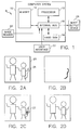
- Figure 1 is a block diagram of an apparatus for correcting values of defect pixels in a digital image in accordance with the present invention;
- Figure 2(a) is a pictorial view of a digital image with a defect pixel region;
- Figure 2(b) is a pictorial view of a defect map for the digital image in Figure 2(a);
- Figure 2(c) is a pictorial view of the window operator used during correction of defect pixels in the digital image in Figure 2(a);
- Figure 2(d) is a pictorial view of a corrected digital image after correction of the defect pixels in the digital image in Figure 2(a);
- Figure 3 is a flow chart illustrating a method for correcting defect pixels in a digital image in accordance with the present invention;
- Figure 4 is a flow chart illustrating a process for estimating corrected values for a defect pixel;
- Figure 5 is a flow chart of another embodiment illustrating a process for estimating corrected values for a defect pixel;
- Figure 6 is a flow chart illustrating an alternative embodiment for defining the line segments in the process for estimating corrected values for a defect pixel in Figures 4 and 5;
- Figure 7 is a pictorial view of the digital image of Figure 2(a) illustrating a line segment being defined as described in Figure 6; and
- Figure 8 is a pictorial view of an example illustrating line segments defined about a defect pixel.
- An
apparatus 8 in accordance with the present invention includes a programmedcomputer system 10 coupled to animage reader 20, animage output device 24, and auser interface 22.Computer system 10 operates according to a set of instructions to correct digital images by correcting values of defect pixels within a defect region in the digital images. With the apparatus and method, defect regions in digital images can be corrected so that regions are entirely unnoticeable to a viewer or less visually discernible because values for defect pixels have been estimated which are consistent with the overall image. - Referring more specifically to Figure 1,
computer system 10 includes aprocessor 12, amemory 14 and ahard disk 18, which are coupled together with aninternal bus 16 for communicating both data and addresses between these components. Preferably, digital images are stored onhard disk 18 insystem 10. -
Image reader 20 is coupled tocomputer system 10, and provides a digital image to thecomputer system 10 viainternal bus 16. This digital image is stored inmemory 14. In this particular embodiment,image reader 20 is a digital scanner or digital camera, such as Kodak Professional Photo-CD 4045 Film Scanner, although any type of device for providing a digital image may be used.Computer system 10 may also receive digital images from other sources, such as digital images stored inhard disk 18. Each digital image is composed of an array of pixel values having one or more color channels. -
Image output device 24 is coupled tocomputer system 10. In this particular embodiment,output device 24 may be any type of digital image output device, such as a video display, a printer, an external non-volatile memory storage device, or a transmission line to other computers within a network. Images stored inmemory 14 may be output toimage output device 24 throughinternal bus 16. -
User interface 22, such as a keyboard or mouse device, is coupled tocomputer system 10 and allows for a user to control and interact withapparatus 8, such as building of a defect map of the digital image stored inmemory 14. User inputs throughuser interface 22 are described later. - Referring to Figures 2(a-d) and 3, the operation of
apparatus 8 will be discussed. Whencomputer system 10 is started atstep 98,system 10 receives a digital image fromimage reader 20 and stores the image in memory 14 (step 100). Alternatively, this image may have already been stored inmemory 14. The image stored inmemory 14 will hereinafter be referred to as the "source image." An example of thesource image 25 is shown in Figure 2(a) withdefect region 26. The source image may be comprised of a single color channel (monochrome), or have multiple color channels, such as RGB. - Once the source image is stored in
memory 14, then instep 102 the defect regions in the source image are located. Preferably, this is performed by the user identifying the approximate image areas containing the defect regions throughuser interface 22, and thenprocessor 12 automatically detecting the defect pixels in those areas identified by the user. One system for identifying defect pixels is disclosed in U.S. Patent Application Serial No. 08/057,942 filed May 4, 1993, now abandoned in favor of Continuation bearing Serial No. 08/412,351 in the name of Robert T. Gray and assigned to the same assignee as this application, and is herein incorporated by reference. Briefly, this defect pixel identification system automatically identifies small local regions of an image which are anomalous in both brightness/color, local contrast, and size, and outputs a map of the defect pixels in the image. Alternatively, the defect pixels may be selected manually by the user, which can be performed by a user generating a digital mask via user interface 22 (for example, by a graphic "painting" software application) identifying the defect pixels. - Once the defect regions are located, a defect map is built and stored in memory 14 (step 104). In the defect map, pixels with a specified value correspond to defect pixels in the source image. One example of a defect map is shown in Figure 2(b) for the
defect region 26 of thesource image 25 in Figure 2(a). In this example, defect pixels are represented by bits set to zero (black), and non-defect pixels are represented by bits set to one (white). - Next, a window operator is set, preferably centered, on a first pixel in the source image (step 106). An example of the
window operator 27 in operation is shown in Figure 2(c). Incomputer system 10, the window operator is used in performing correction of defect pixel values in the source image. The window operator defines a region of interest in the source image about a pixel centered within the region. In the preferred embodiment, the shape and size of this window operator is a square region, where each side or boundary of the square region is X in size. However in another embodiment, the window operator may be a circular region having a diameter X. This window operator is used byprocessor 12 to scan across each pixel in the lines of the source image. The scanning pattern of the window operator is not critical as long as all defect pixels are visited during scanning. For example, a raster-scan pattern may be used. - In
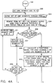
step 107, a check is made to determine whether this pixel set within the window operator is a defect pixel by referencing the defect map stored inmemory 14. If the pixel is a non-defect pixel, then instep 109 the values of this non-defect pixel are stored in an area ofmemory 14 which is allocated for storing the corrected source image ("corrected image"). If the pixel is a defect pixel, then the defect pixel is selected ("PIXELSEL") for subsequent correction (step 108). Next, a corrected value in each channel of PIXELSEL is estimated (step 110). Figure 2(c) shows an illustration ofwindow operator 27 and the estimation of corrected values for a defect pixel in thedefect region 26 of thesource image 25. The process for estimating corrected values is described in greater detail in Figure 4. - Referring to Figure 4, the process for estimating corrected values for PIXELSEL is started at
step 198. The line segment size is set to X for every direction (step 200). Preferably, X is at least twice the maximum width of the defect region in the source image. A SET of line segments or vectors is defined or allocated through PIXELSEL wherein each line segment is composed of both defect and non-defect pixels in the source image on one or both sides of PIXELSEL (step 202). In this embodiment, the total number of pixels defect and non-defect pixels, in each line segment is maintained the same, which corresponds to the square window operator. Alternatively, each line segment can have the same length X defined as the Euclidean distance, which corresponds to the circular window operator. However, in other embodiments the total number of pixels in each line segment may vary depending on the defect pixel and line segment, as will be described later. - SET is composed of N number of line segments, where each line segment is represented by the following notation: In SET, n refers to each line segment (n=1 to N). Each line segment n has pixels having values for K number of color channels. The nth line segment is referred to as LSn. The kth channel of the nth line segment in SET is referred to as LSn,k. For example, where SET has 4 line segments (N=4), and each pixel has 3 channel values (K=3), the 2nd channel of the 3rd line segment in SET is LS3,2.
- Preferably, the line segments are each at equal radial angles at 45° or 22.5° intervals with respect to each other about PIXELSEL, although the angles can vary as needed. The number of line segments in SET depends on size of this angle. For example, radial angles at 45° intervals provide 4 line segments in SET, while radial angles at 22.5° intervals provides 8 line segments in SET. Preferably, each line segment is composed of pixels which are less than 0.5 pixel distance away from a line through PIXELSEL at the radial angle associated with each respective line segment.
- Referring to Figure 8, an example of a SET of 4 line segments (H, V, D1, and D2) is shown at 45° spacing to each other, where each line segment is composed of a total of 22 pixels and has 11 pixels on each side of PIXELSEL.
- Referring back to Figure 4, once the SET of line segments is defined, then at
step 204 any line segments which do not contain a minimum threshold number of non-defect pixels on each side of PIXELSEL are considered not valid line segments, and are removed from SET. Preferably, the minimum threshold is set to one-half the number of pixels on one side of a line segment. For example, if each line segment has 8 pixels, then 4 pixels are on each side of PIXELSEL and the minimum threshold is 2 pixels. Accordingly, any line segment which does not have at least 2 non-defect pixels on each side of PIXELsel is removed from SET. - Next, a check is then performed to determine whether the remaining number of line segments N in SET is greater than zero (step 206). If N is not greater than zero, then the "no" branch is taken to step 207 where all the line segments previously removed are replaced in SET. Once the line segments are replaced, a query is made to determine whether any of the line segments have non-defect pixels (step 209). If there are no non-defect pixels in the line segments of SET, then the "no" branch is taken to step 211 where the line segment size X is increased by Y. This accordingly expands the window operator region by Y, thereby increasing the possibility that when SET is redefined line segments will include non-defect pixels. A new SET of line segments is redefined through PIXELSEL at this increased line segment size at
step 202, and the process as described above is repeated. If the line segments atstep 209 contain any non-defect pixels, then the "yes" branch is taken to step 213 where an estimated value for each channel k of PIXELSEL is calculated based on the weighted average of the non-defect pixels in SET. These weights are determined by their respective distances from PIXELSEL. - The calculation for estimating values for each channel k of PIXELSEL at
step 213 preferably is as follows:
- i
- = index for each non-defect pixel in SET;
- Q
- = total number of non-defect pixels in SET;
- P i,k
- = the value of the kth channel of the ith non-defect pixel in SET; and
- W i
- = the weight for the ith non-defect pixel in SET, where

- x i and y i
- = the x and y coordinates of the ith non-defect pixel in SET in the source image, and
- x SEL and y SEL
- = the x and y coordinates of PIXELSEL in the source image
- If at
step 206 the number of line segments N is greater than zero, then the "yes" branch is taken to step 208 where a functional model is calculated for the non-defect pixel values for each channel k of each line segment in SET. The functional model calculation is performed by fitting the values of the non-defect pixels in a line segment to a mathematical model, such as a flat field fit, linear fit, or quadratic fit. This fitting is based on the values of the non-defect pixels, and the distances between them. A variety of techniques may be used for modeling the non-defect pixel values, and the particular technique chosen will affect model accuracy, and require a different minimum number of non-defect pixels. One example of this technique is shown in W. PRESS, S. TEUKOLSKY, W. VETTERLING, AND B. FLANNERY, NUMERICAL RECIPES IN FORTRAN, Ch. 15 (2d ed., 1992), which is herein incorporated by reference. In the preferred embodiment, the functional model calculation atstep 208 uses a linear least-squares fit, which requires at least one non-defect pixel lying on each side of PIXELSEL. Earlier performedstep 204 may be used to assure that this minimum is met for all line segments in SET. - Next at
step 210, a mean square fitting error (MSE) is calculated of the non-defect pixel values from the functional model for each channel of each line segment in SET. The MSE calculation is a statistical measure of the deviation of the non-defect pixel values in a line segment from an estimate of their values based on their functional fit. Thus, the lower a MSE value the more consistent to the model are the non-defect pixel values. For a given channel and line segment, MSE is calculated by determining the difference between the value of each non-defect pixel from its value estimated along the functional model. The resulting difference for each non-defect pixel is then squared, and the sum of these squares is averaged to obtain the MSE. (In the case of a flat field fit for the functional model calculation, the MSE is equivalent to the variance of the non-defect pixels in the line segment.) Mean square fitting error of the kth channel of the nth line segment (MSEn,k) is calculated by:
- M n
- = number of non-defect pixels in LSn;
- i
- = index for each non-defect pixel in LSn from 1 to Mn;
- P i,n,k
- = the actual value of the ith non-defect pixel in channel k in LSn; and
- p i,n,k
- = the functional model estimate value of the ith non-defect pixel in channel k in LSn.
- Then at
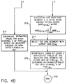
step 212, a calculation is performed for each line segment wherein each channel of the line segment is combined to provide a total mean square fitting error valuewhere:

- K
- = the total number of channels (for RGB, K=3); and
- k
- = index for each channel from 1 to K.
- The line segment having the lowest MSETotal is then selected (step 214). The selected line segment represents the preferred line segment for determining estimated values for PIXELSEL. An estimated value for each channel k of PIXELSEL is then interpolated using at least one non-defect pixel of the selected line segment on each side of PIXELSEL (step 216). In this manner, by selecting the line segment with the lowest total mean square fitting error, the line segment representing non-defect pixels which are most consistent to their functional model across all channels is used in determining the estimated values for PIXELSEL. Once the estimation of values for PIXELSEL is completed (step 218) then processing goes to step 112 in Figure 3.
- Referring to Figure 8, an example of the processing in Figure 4 is described below. Figure 8 shows an expanded view of a source image with a defect region extending from
Region 1 toRegion 2, wherein each region is composed of pixels with similar pixel values, which are distinct between regions. There are 4 line segments in SET labeled H, V, D1 and D2, which are defined through PIXELSEL at the center or intersection of the line segments (step 202). Once defined, line segment H and D2 are removed from SET because each has a side without any non-defect pixels, and therefore is below a minimum threshold of 4 non-defect pixels (step 204). Next, a functional model is fitted and a mean square fitting error is calculated for remaining line segments V and D1 (steps 208-210). In the single color channel (K=1) example of Figure 8, the mean square fitting error for line segment D1 is lower than the mean square fitting error for line segment V. This is due to the excessive fitting error for dissimilar non-defect pixel values along line segment V extending throughRegion 1 andRegion 2. In contrast, the non-defect pixels of line segment D1 all lie withinRegion 1 and have uniform pixel values. Thus line segment D1 has a lower fitting error than line segment V. Consequently, atstep 214 line segment D1 is selected, and atstep 216 PIXELSEL is replaced with an estimate value based upon the non-defect pixels in line segment D1. - Referring to Figure 5, an alternative embodiment for estimating corrected values for PIXELSEL is illustrated. Corresponding steps in Figure 5 have numeral designations which correspond to those in Figure 4 and will not be described again. Accordingly, once the mean square error calculations are made at
step 210, then a weight (wn,k) is calculated atstep 220 for each channel k for each line segment n in SET, where: is calculated for each channel k (step 224), where:

step 204. But, since line segment D1 has a lower mean square fitting error than line segment V, the intermediate estimate value for line segment D1 contributes significantly more to the final estimate value of PIXELSEL than the intermediate estimate value for line segment V. Once the estimation of values for PIXELSEL is completed (step 216) then processing goes to step 112 in Figure 3. - Referring back to Figure 3, once estimated values for PIXELSEL are calculated, then at
step 112 they are stored in the corrected image area ofmemory 14. A check is then made atstep 114 to determine whether the end of the source image has been reached. In other words, have all pixels in the source image been scanned by the window operator. If not, then the "no" branch is taken to step 115 where the window operator is advanced, and set, preferably centered, to the next pixel in the image and steps 107-114 are repeated as previously described. - Once the end of image is reached, the "yes" branch is taken from
step 114 to step 116, where the corrected image stored inmemory 14 is output to theimage output device 24 atstep 116 and the end of the process atstep 118. An example of the corrected image is shown in Figure 2(d), wherein thedefect 26 has been corrected and is no longer visually discernible. - In two alternative embodiments, the size of each line segment at
step 202 in Figures 4 and 5 is variable along its respective radial line through PIXELSEL. Thus, step 200 for setting the line segment size is no longer needed. Line segments are extended on both sides of PIXELSEL. The composition of each line segment is determined by extending each line segment along a vector (that is, its respective radial line) from each side of PIXELSEL as described below. - In the first alternative embodiment, line segments are separately extended on each opposite side of PIXELSEL on a vector along its respective radial line until each side is composed of a certain number of non-defect pixels, ND, (not shown or described with respect to Figures 4 and 5). Preferably, ND represents two or three non-defect pixels. If a line segment cannot be extended on either side of PIXELSEL to include ND non-defect pixels, then that line segment is not included in SET. This can occur because the line segment extension reached the outer edge of the source image (or defect map) or a maximum distance from PIXELSEL without locating ND non-defect pixels. Once both sides of any line segment include ND non-defect pixels, it is assured that the line segment has a proper number of non-defect pixels for subsequent processing.
- Referring to Figures 6 and 7, the second alternative embodiment will now be discussed. Figure 6 is a flow chart describing the extension of one side of line segment LSn from PIXELSEL. Starting at
step 226, multiplier A is first set to 1 (step 228). Variable Q is then set to a desired initial number of non-defect pixels from PIXELSEL, and variable E to a desired increment number of non-defect pixels (step 230). Next, the first Q adjacent non-defect pixels for the line segment LSn extension from PIXELSEL is set asGroup 1 along a vector corresponding to line segment LSn radial line (step 232). A series of stopping conditions for extending line segment LSn are then checked. First, ifGroup 1 cannot be established either due to the lack of Q adjacent non-defect pixels or that the edge of the source image (or defect map) was reached, thenpath 262 fromstep 232 is followed to step 260 where line segment LSn is not included in SET. Next a check is performed to determine whether the number of pixels inGroup 1 exceeds a maximum threshold of line segment non-defect pixels THMAX (step 236). If so, then the "yes" branch is taken to step 257 where the line segment LSn extension stops at the pixel inGroup 1 before THMAX was exceeded. THMAX represents the maximum number of non-defect pixels any one side of PIXELSEL may be composed of. - If the number of pixels in
Group 1 does not exceed THMAX, then the "no" branch is taken to step 238 where the first
Group 1 is set asGroup 2. IfGroup 2 cannot be established either due to a lack of
path 263 is taken to step 261 where line segment LSn extension stops at the last pixel inGroup 1. Q represents a base number of non-defect pixels in line segment LSn, and E represents the number of successive non-defect pixels added to that base number in each iteration of the extension process, as will be shown below. - Figure 7 illustrates an example of extending line segment LSn along a
vector 28 from PIXELSEL indefect region 26 ofsource image 25. The black dots alongvector 28 in Figure 7 represent adjacent non-defect pixels from PIXELSEL (not drawn to scale). In this example, Q equals 3 and E equals 2. Thus,Group 1 comprises the first three adjacent non-defect pixels closest the PIXELSEL, andGroup 2 comprises five non-defect pixels, that is, the three non-defect pixels inGroup 1 and the next two adjacent non-defect pixels from PIXELSEL after the non-defect pixels ofGroup 1. - Next, a functional model is calculated for each channel k of the pixels in each group. Then, at step 240 a mean square fitting error (MSEg,k) is calculated for each channel k of their non-defect pixels from their model, where g = 1 and 2, representing
Group 1 andGroup 2 respectively. Functional model and MSE calculations were described earlier in reference to Figure 4. Next, the MSE's for each channel of each group are summed to provide a sum mean square error value (SMSEg) for each group g (step 242), where:
- Next, a RATIO is calculated for the sum mean square errors of
Group 2 toGroup 1, RATIO = SMSE2/Max [SMSE1, TH2], where TH2 is greater than 0 and the Max function selects the greater of the two terms SMSE1, and TH2 (step 244). - The next three checks are based upon SMSE1, SMSE2 and RATIO. The first check is performed only once at the beginning of the extension process when A = 1. The first check is whether the sum mean square error calculated for
Group 1, SMSE1, is greater than a first threshold, TH1 (step 246). If so, then the "yes" branch is taken to step 254 where line segment LSn is not included in SET. The second check is whether the sum mean square error ofGroup 2, SMSE2, is greater than the first threshold, TH1 (step 247). The third check is whether RATIO is greater than a third threshold, TH3 (step 248). These three thresholds TH1, TH2, and TH3 are empirically determined such that the more statistically consistent the values of the non-defect pixels are within each group to their model, the further line segment LSn will extend from PIXELSEL. Preferably, these thresholds are selected to provide that TH1 is greater than TH2, and TH3 is greater than 1. If all three checks atsteps Group 1 pixels are replaced with the pixels ofGroup 2. Then, A is indexed by one (step 251) and steps 236-248 are repeated as previously described, whereinGroup 2 now includes the next E adjacent non-defect pixels from PIXELSEL in addition to the pixels ofGroup 1. Using Figure 7 as an example,Group 1 now has five non-defect pixels from PIXELSEL andGroup 2 has seven non-defect pixels from PIXELSEL alongvector 28. If either the second check (step 247) or third check (step 248) is true, then their "yes" branch is taken to step 253 where the line segment LSn extension stops at the last non-defect pixel furthest from PIXELSEL inGroup 1.Groups - Once the extension of one side of line segment LSn from PIXELSEL is completed, without an indication of non-inclusion in SET, the above process is repeated for the other side of line segment LSn. In this manner, the total composition of defect and non-defect pixels for each side of line segment LSn is determined or fixed. The above is repeated for each line segment through PIXELSEL. Finally, the SET of line segments defined at
step 202 comprises the line segments which are extended on both sides of PIXELSEL without a non-inclusion indication. - Of the above two alternative embodiment, the second embodiment is preferred because it employs statistical analysis of non-defect pixel values (for example, SMSE) in extending line segments, rather than a constant number of non-defect pixels ND. Further, in the second embodiment, those skilled in the art can appreciate other types of stopping conditions may also be used than those described to provide different line segment extension criteria.
- Preferably in this apparatus, once non-defect pixels have been estimated and stored in the corrected image (
steps - From the foregoing description, it will be apparent that there has been provided an improved method and apparatus for correcting pixel values in a digital image. Variations and modifications in the herein described system in accordance with the invention will undoubtedly suggest themselves to those skilled in the art. Accordingly, the foregoing description should be taken as illustrative and not in a limiting sense.
- 8
- Apparatus
- 10
- Computer System
- 12
- Processor
- 14
- Memory
- 16
- Internal Bus
- 18
- Hard disk
- 20
- Image reader
- 22
- User interface
- 24
- Image output device
- 25
- Source Image Example
- 26
- Defect Example
- 27
- Window Operator Example
- 28
- Vector
- 98-261
- Steps
- 262-263
- Paths
Claims (10)
- A method for correcting one or more defect pixels in a source image with non-defect pixels and the defect pixels, each of the defect pixels and the non-defect pixels being represented by at least one defect pixel signal and non-defect pixel signal, respectively, the method comprising the steps of:selecting one of the defect pixels;allocating a plurality of line segments through the selected defect pixel, wherein each the line segment is composed of the defect pixels and the non-defect pixels about the selected defect pixel;determining at least one representative model of the non-defect pixel signals along each the line segment;determining the deviation of the non-defect pixel signals along each the line segment from the model corresponding to the line segment;selecting the line segment having the lowest deviation; anddetermining corrected pixel signals for the selected defect pixel based on at least two of the non-defect pixel signals in the selected line segment.
- A method as claimed in Claim 1 wherein one or more of the defect pixels are located within a defect region of the source image, and the step ofselecting one of the defect pixels includes selecting one of the defect pixels in the defect region.
- A method as claimed in Claim 1 wherein:
the defect pixel signals represent channel signals of their corresponding defect pixels;
the non-defect pixel signals represent channel signals of their corresponding non-defect pixels;
the model determining step further comprises determining a representative model based upon corresponding channel signals of the non-defect pixels along each the line segment; and
the deviation determining step further comprises determining a deviation of corresponding channel signals of the non-defect pixels along each the line segment from the model of the channel signals of the non-defect pixels along the line segment. - A method as claimed in Claim 3 wherein:
the deviation determining step further comprises the step of determining a total for each the line segment based on the deviation of the channel signals of the non-defect pixels;
the line segment selecting step further comprises the step of selecting the line segment having the lowest total; and
the pixel signals determining step further comprises determining corrected channel signals for the selected defect pixel based on the channel signals of at least two of the non-defect pixels in the selected line segment. - A method for correcting one or more defect pixels in a source image with non-defect pixels and the defect pixels, each of the defect pixels and the non-defect pixels being represented by at least one defect pixel signal and non-defect pixel signal, respectively, the method comprising the steps of:selecting one of the defect pixels;allocating a plurality of line segments through the selected defect pixel, wherein each the line segment is composed of the defect pixels and the non-defect pixels about the selected defect pixel;determining at least one representative model of the non-defect pixel signals along each the line segment;determining the deviation of the non-defect pixel signals along each the line segment from the model corresponding to the line segment;determining first pixel signals representing the selected defect pixel for each the line segment based on at least two non-defect pixel signals in the line segment; anddetermining second pixel signals representing the selected defect pixel based on the first pixel signals for each line segment, wherein the second pixel signals are based upon a contribution of each the first pixel signals of each the line segment relative to their respective deviation.
- An apparatus for correcting values of defect pixels in a source image having a programmed computer with memory for storing the source image, the stored source image comprising a plurality of pixels having signals representing values of one or more color channels, and a defect region comprising the pixels within the plurality having corrupted values, wherein the pixels in the defect region are defect pixels, and the pixels outside the defect region are non-defect pixels, the apparatus comprising:means for selecting one of the defect pixels in the defect region;means for allocating a plurality of line segments through the selected defect pixel, wherein each the line segment is composed of pixels in the source image about the selected defect pixel;means for determining for each channel of each the line segment a representative model of the non-defect pixels values;means for determining for each channel of each the line segment the deviation of the non-defect pixels values in the line segment from their representative model;means for determining a total for each line segment based on the deviation for each channel of the line segment;means for selecting the line segment having the lowest the total deviation from among the plurality of line segments; andmeans for determining a value for each channel of the selected defect pixel based on the values of at least two of the non-defect pixels in the selected line segment.
- An apparatus for correcting values of defect pixels in a source image having a programmed computer with memory for storing the source image, the stored source image comprising a plurality of pixels having signals representing values of one or more color channels, and a defect region comprising the pixels within the plurality having corrupted values, wherein the pixels in the defect region are defect pixels, and the pixels outside the defect region are non-defect pixels, the apparatus comprising:means for selecting one of the defect pixels in the defect region;means for allocating a plurality of line segments through the selected defect pixel, wherein each the line segment is composed of pixels in the source image about the selected defect pixel;means for determining for each channel of each the line segment a representative model of the non-defect pixels values;means for determining for each channel of each the line segment the deviation of the non-defect pixels values in the line segment from their representative model;means for determining for each channel of each the line segment a first value for the selected defect pixel based on the values of at least two non-defect pixels in the line segments; andmeans for determining a second value for each channel of the selected defect pixel based on the first value for each channel of each line segment, wherein the second value is based upon a contribution of each the first value for each channel of each the line segment relative to their respective the deviation.
- An apparatus for correcting one or more defect pixels in a source image with non-defect pixels and the defect pixels, each of the defect pixels and the non-defect pixels being represented by at least one defect pixel signal and non-defect pixel signal, respectively, the apparatus comprising:means for selecting one of the defect pixels;means for allocating a plurality of line segments through the selected defect pixel, wherein each the line segment is composed of the defect pixels and the non-defect pixels about the selected defect pixel;means for determining at least one representative model of the non-defect pixel signals along each the line segment;means for determining the deviation of the non-defect pixel signals along each the line segment from the model corresponding to the line segment;means for selecting the line segment having the lowest deviation; andmeans for determining corrected pixel signals for the selected defect pixel based on at least two of the non-defect pixel signals in the selected line segment.
- An apparatus for correcting one or more defect pixels in a source image with non-defect pixels and the defect pixels, each of the defect pixels and the non-defect pixels being represented by at least one defect pixel signal and non-defect pixel signal, respectively, the apparatus comprising:means for selecting one of the defect pixels;means for allocating a plurality of line segments through the selected defect pixel, wherein each the line segment is composed of the defect pixels and the non-defect pixels about the selected defect pixel;means for determining at least one representative model of the non-defect pixel signals along each the line segment;means for determining the deviation of the non-defect pixel signals along each the line segment from the model corresponding to the line segment;means for determining first pixel signals representing the selected defect pixel for each the line segment based on at least two non-defect pixel signals in the line segment; andmeans for determining second pixel signals representing the selected defect pixel based on the first pixel signals for each line segment, wherein the second pixel signals are based upon a contribution of each the first pixel signals of each the line segment relative to their respective deviation.
- An apparatus for correcting values of defect pixels in a source image having a programmed computer with memory for storing the source image, the stored source image comprising a plurality of pixels having signals representing values of one or more color channels, and a defect region comprising the pixels within the plurality having corrupted values, wherein the pixels in the defect region are defect pixels, and the pixels outside the defect region are non-defect pixels, the apparatus comprising:the processor selects of one of the defect pixels in the defect region; allocates a plurality of line segments through the selected defect pixel wherein each the line segment is composed of pixels in the source image about the selected defect pixel, determines for each channel of each the line segment a representative model of the non-defect pixels values, determines for each channel of each the line segment the deviation of the non-defect pixels values in the line segment from their representative model, determines a total for each line segment based on the deviation for each channel of each line segment, selects the line segment having the lowest the total from among the plurality of line segments, and determines a value for each channel of the selected defect pixel based on the values of at least two of the non-defect pixels in the selected line segment.
Applications Claiming Priority (4)
| Application Number | Priority Date | Filing Date | Title |
|---|---|---|---|
| US652595P | 1995-10-16 | 1995-10-16 | |
| US6525 | 1995-10-16 | ||
| US08/675,320 US6104839A (en) | 1995-10-16 | 1996-07-10 | Method and apparatus for correcting pixel values in a digital image |
| US675320 | 1996-07-10 |
Publications (3)
| Publication Number | Publication Date |
|---|---|
| EP0768621A2 true EP0768621A2 (en) | 1997-04-16 |
| EP0768621A3 EP0768621A3 (en) | 1998-07-15 |
| EP0768621B1 EP0768621B1 (en) | 2003-06-18 |
Family
ID=50630520
Family Applications (1)
| Application Number | Title | Priority Date | Filing Date |
|---|---|---|---|
| EP96202771A Expired - Lifetime EP0768621B1 (en) | 1995-10-16 | 1996-10-04 | Method and apparatus for correcting pixel values in a digital image |
Country Status (3)
| Country | Link |
|---|---|
| US (1) | US6104839A (en) |
| EP (1) | EP0768621B1 (en) |
| DE (1) | DE69628711T2 (en) |
Cited By (22)
| Publication number | Priority date | Publication date | Assignee | Title |
|---|---|---|---|---|
| DE19842572A1 (en) * | 1998-09-17 | 2000-03-23 | Heidelberger Druckmasch Ag | Automatic removal method for effect of scratches in digital image data, involves using masking process |
| JP2001008928A (en) * | 1999-04-30 | 2001-01-16 | General Electric Co <Ge> | Method and device for display of image |
| WO2001027688A2 (en) * | 1999-10-08 | 2001-04-19 | Applied Science Fiction, Inc. | System and method for correcting defects in digital images through selective fill-in from surrounding areas |
| US6380539B1 (en) | 1997-01-30 | 2002-04-30 | Applied Science Fiction, Inc. | Four color trilinear CCD scanning |
| US6393160B1 (en) | 1998-03-13 | 2002-05-21 | Applied Science Fiction | Image defect correction in transform space |
| US6437358B1 (en) | 1999-02-04 | 2002-08-20 | Applied Science Fiction, Inc. | Apparatus and methods for capturing defect data |
| US6442301B1 (en) | 1997-01-06 | 2002-08-27 | Applied Science Fiction, Inc. | Apparatus and method for defect channel nulling |
| US6487321B1 (en) | 1999-09-16 | 2002-11-26 | Applied Science Fiction | Method and system for altering defects in a digital image |
| US6498867B1 (en) | 1999-10-08 | 2002-12-24 | Applied Science Fiction Inc. | Method and apparatus for differential illumination image-capturing and defect handling |
| WO2003019472A1 (en) * | 2001-08-24 | 2003-03-06 | Polaroid Corporation | Method and system for user assisted defect removal |
| WO2003019473A1 (en) * | 2001-08-24 | 2003-03-06 | Polaroid Corporation | Method and apparatus for detection and removal of scanned image scratches and dust |
| US6590679B1 (en) | 1998-02-04 | 2003-07-08 | Applied Science Fiction, Inc. | Multilinear array sensor with an infrared line |
| US6593558B1 (en) | 1996-05-10 | 2003-07-15 | Applied Science Fiction, Inc. | Luminance-priority electronic color image sensor |
| US6683995B2 (en) | 1999-12-23 | 2004-01-27 | Eastman Kodak Company | Method and apparatus for correcting large defects in digital images |
| US6704458B2 (en) | 1999-12-29 | 2004-03-09 | Eastman Kodak Company | Method and apparatus for correcting heavily damaged images |
| US6711302B1 (en) | 1999-10-20 | 2004-03-23 | Eastman Kodak Company | Method and system for altering defects in digital image |
| US6720560B1 (en) | 1999-12-30 | 2004-04-13 | Eastman Kodak Company | Method and apparatus for scanning images |
| US6750435B2 (en) | 2000-09-22 | 2004-06-15 | Eastman Kodak Company | Lens focusing device, system and method for use with multiple light wavelengths |
| US6862117B1 (en) | 1999-12-30 | 2005-03-01 | Eastman Kodak Company | Method and apparatus for reducing the effect of bleed-through on captured images |
| US6924911B1 (en) | 1999-10-12 | 2005-08-02 | Eastman Kodak Company | Method and system for multi-sensor signal detection |
| US6987892B2 (en) | 2001-04-19 | 2006-01-17 | Eastman Kodak Company | Method, system and software for correcting image defects |
| US7164511B2 (en) | 1999-12-29 | 2007-01-16 | Eastman Kodak Company | Distinguishing positive and negative films system and method |
Families Citing this family (50)
| Publication number | Priority date | Publication date | Assignee | Title |
|---|---|---|---|---|
| US7042505B1 (en) | 1997-10-09 | 2006-05-09 | Fotonation Ireland Ltd. | Red-eye filter method and apparatus |
| US7630006B2 (en) | 1997-10-09 | 2009-12-08 | Fotonation Ireland Limited | Detecting red eye filter and apparatus using meta-data |
| US7738015B2 (en) | 1997-10-09 | 2010-06-15 | Fotonation Vision Limited | Red-eye filter method and apparatus |
| US6806902B1 (en) * | 1999-06-08 | 2004-10-19 | Chrontel, Inc. | System and method for correcting bad pixel data in a digital camera |
| US6995794B2 (en) * | 1999-06-30 | 2006-02-07 | Logitech Europe S.A. | Video camera with major functions implemented in host software |
| TW575855B (en) * | 1999-08-05 | 2004-02-11 | Sharp Kk | Display device |
| US6731806B1 (en) * | 1999-10-08 | 2004-05-04 | Eastman Kodak Company | Region growing based noise reduction method for digital images |
| US6724945B1 (en) * | 2000-05-24 | 2004-04-20 | Hewlett-Packard Development Company, L.P. | Correcting defect pixels in a digital image |
| EP1297687A1 (en) * | 2000-06-23 | 2003-04-02 | Koninklijke Philips Electronics N.V. | Image sensor signal defect correction |
| US6498831B2 (en) * | 2000-12-22 | 2002-12-24 | Ge Medical Systems Global Technology Company, Llc | Panel detector pixel replacement method and apparatus |
| US6547409B2 (en) * | 2001-01-12 | 2003-04-15 | Electroglas, Inc. | Method and apparatus for illuminating projecting features on the surface of a semiconductor wafer |
| US6697126B2 (en) * | 2001-02-09 | 2004-02-24 | Webtv Networks, Inc. | Intra-frame video error concealment |
| US6990255B2 (en) * | 2001-09-19 | 2006-01-24 | Romanik Philip B | Image defect display system |
| DE10212919B4 (en) * | 2002-03-22 | 2004-11-11 | Heidelberger Druckmaschinen Ag | Process for the automatic detection of image defects |
| US7889211B2 (en) * | 2002-04-15 | 2011-02-15 | Tektronix, Inc. | Measuring PSNR of full color video |
| US7082211B2 (en) * | 2002-05-31 | 2006-07-25 | Eastman Kodak Company | Method and system for enhancing portrait images |
| US7209599B2 (en) * | 2002-07-12 | 2007-04-24 | Hewlett-Packard Development Company, L.P. | System and method for scanned image bleedthrough processing |
| AU2003286453A1 (en) * | 2002-10-15 | 2004-05-04 | David J. Mcintyre | System and method for simulating visual defects |
| JP4377404B2 (en) * | 2003-01-16 | 2009-12-02 | ディ−ブルアー テクノロジス リミテッド | Camera with image enhancement function |
| US7039222B2 (en) * | 2003-02-28 | 2006-05-02 | Eastman Kodak Company | Method and system for enhancing portrait images that are processed in a batch mode |
| US7920723B2 (en) | 2005-11-18 | 2011-04-05 | Tessera Technologies Ireland Limited | Two stage detection for photographic eye artifacts |
| US8254674B2 (en) | 2004-10-28 | 2012-08-28 | DigitalOptics Corporation Europe Limited | Analyzing partial face regions for red-eye detection in acquired digital images |
| US7574016B2 (en) | 2003-06-26 | 2009-08-11 | Fotonation Vision Limited | Digital image processing using face detection information |
| US7336821B2 (en) | 2006-02-14 | 2008-02-26 | Fotonation Vision Limited | Automatic detection and correction of non-red eye flash defects |
| US7970182B2 (en) | 2005-11-18 | 2011-06-28 | Tessera Technologies Ireland Limited | Two stage detection for photographic eye artifacts |
| US8170294B2 (en) | 2006-11-10 | 2012-05-01 | DigitalOptics Corporation Europe Limited | Method of detecting redeye in a digital image |
| US8036458B2 (en) | 2007-11-08 | 2011-10-11 | DigitalOptics Corporation Europe Limited | Detecting redeye defects in digital images |
| US7792970B2 (en) | 2005-06-17 | 2010-09-07 | Fotonation Vision Limited | Method for establishing a paired connection between media devices |
| US7689009B2 (en) | 2005-11-18 | 2010-03-30 | Fotonation Vision Ltd. | Two stage detection for photographic eye artifacts |
| US8520093B2 (en) | 2003-08-05 | 2013-08-27 | DigitalOptics Corporation Europe Limited | Face tracker and partial face tracker for red-eye filter method and apparatus |
| US9412007B2 (en) | 2003-08-05 | 2016-08-09 | Fotonation Limited | Partial face detector red-eye filter method and apparatus |
| US20050140801A1 (en) * | 2003-08-05 | 2005-06-30 | Yury Prilutsky | Optimized performance and performance for red-eye filter method and apparatus |
| JP4709514B2 (en) * | 2004-09-16 | 2011-06-22 | オリンパス株式会社 | Capsule endoscope system |
| GB0505443D0 (en) * | 2005-03-17 | 2005-04-20 | Dmist Technologies Ltd | Image processing methods |
| US8179575B2 (en) * | 2005-06-14 | 2012-05-15 | Carl Zeiss Microimaging Gmbh | Chromatic registration for biological sample imaging |
| US20070091109A1 (en) * | 2005-09-13 | 2007-04-26 | Roscoe Atkinson | Image quality |
| US7599577B2 (en) | 2005-11-18 | 2009-10-06 | Fotonation Vision Limited | Method and apparatus of correcting hybrid flash artifacts in digital images |
| US20070257866A1 (en) * | 2006-05-08 | 2007-11-08 | Eastman Kodak Company | Method and apparatus for defect correction in a display |
| EP2033142B1 (en) | 2006-06-12 | 2011-01-26 | Tessera Technologies Ireland Limited | Advances in extending the aam techniques from grayscale to color images |
| US8055067B2 (en) | 2007-01-18 | 2011-11-08 | DigitalOptics Corporation Europe Limited | Color segmentation |
| US20080187184A1 (en) * | 2007-02-01 | 2008-08-07 | Kabushiki Kaisha Toshiba | System and method for facial image enhancement |
| JP2010520567A (en) | 2007-03-05 | 2010-06-10 | フォトネーション ビジョン リミテッド | Red-eye false detection filtering using face position and orientation |
| US8503818B2 (en) | 2007-09-25 | 2013-08-06 | DigitalOptics Corporation Europe Limited | Eye defect detection in international standards organization images |
| US8212864B2 (en) | 2008-01-30 | 2012-07-03 | DigitalOptics Corporation Europe Limited | Methods and apparatuses for using image acquisition data to detect and correct image defects |
| US8081254B2 (en) | 2008-08-14 | 2011-12-20 | DigitalOptics Corporation Europe Limited | In-camera based method of detecting defect eye with high accuracy |
| CN101990046B (en) * | 2009-07-31 | 2014-03-26 | 鸿富锦精密工业(深圳)有限公司 | Digital image detection system and method |
| US9967481B2 (en) * | 2013-03-13 | 2018-05-08 | Intel Corporation | Techniques for image sensor pixel correction |
| JP6348108B2 (en) * | 2013-03-27 | 2018-06-27 | 株式会社日立製作所 | Image processing apparatus, radiation imaging apparatus, and image processing method |
| KR102246873B1 (en) * | 2014-11-17 | 2021-04-30 | 삼성전자 주식회사 | A method removing a bad pixel of pixel image generated by an image sensor, a image sensor using the method, and a application processor using the method |
| CN110991082B (en) * | 2019-12-19 | 2023-11-28 | 信利(仁寿)高端显示科技有限公司 | Mura quantification method based on excimer laser annealing |
Citations (4)
| Publication number | Priority date | Publication date | Assignee | Title |
|---|---|---|---|---|
| US5036405A (en) * | 1986-11-19 | 1991-07-30 | Canon Kabushiki Kaisha | Image amending method |
| EP0457562A1 (en) * | 1990-05-17 | 1991-11-21 | Crosfield Electronics Limited | Control data array modification |
| EP0624848A2 (en) * | 1993-05-04 | 1994-11-17 | Eastman Kodak Company | A technique for the detection and removal of local defects in digital continuous-tone images |
| EP0778543A2 (en) * | 1995-12-04 | 1997-06-11 | Eastman Kodak Company | A gradient based method for providing values for unknown pixels in a digital image |
Family Cites Families (12)
| Publication number | Priority date | Publication date | Assignee | Title |
|---|---|---|---|---|
| DE3121599C2 (en) * | 1981-05-30 | 1986-11-27 | Robert Bosch Gmbh, 7000 Stuttgart | Method and circuit arrangement for concealing errors in a digital video signal |
| JPS5810032A (en) * | 1981-07-09 | 1983-01-20 | オリンパス光学工業株式会社 | Endoscope |
| DE3636077C2 (en) * | 1986-10-23 | 1993-10-07 | Broadcast Television Syst | Method for masking errors in a video signal and circuit for carrying out the method |
| JPS63232579A (en) * | 1987-03-19 | 1988-09-28 | Mitsubishi Electric Corp | Solid-state image pickup device |
| US4910694A (en) * | 1988-01-11 | 1990-03-20 | Eastman Kodak Co | Method for approximating a value which is a nonlinear function of the linear average of pixel data |
| US5008739A (en) * | 1989-02-13 | 1991-04-16 | Eastman Kodak Company | Real-time digital processor for producing full resolution color signals from a multi-color image sensor |
| DE3942273A1 (en) * | 1989-12-21 | 1991-06-27 | Broadcast Television Syst | METHOD FOR HIDDEN ERRORS IN A VIDEO SIGNAL |
| EP0496573B1 (en) * | 1991-01-24 | 1995-12-20 | Matsushita Electric Industrial Co., Ltd. | Pixel defect removing circuit for solid-state image pickup device |
| CA2041848C (en) * | 1991-05-06 | 2000-08-01 | Martin Levesque | Method for removing the effects of particulate matter from sequences of images |
| US5214470A (en) * | 1992-04-09 | 1993-05-25 | Xerox Corporation | Method and apparatus for compensating for dirt or etched areas on a document platen |
| US5365604A (en) * | 1993-01-14 | 1994-11-15 | Rca Thomson Licensing Corporation | Error concealment apparatus for video signal processors |
| JP3442466B2 (en) * | 1993-04-12 | 2003-09-02 | 株式会社リコー | Image processing apparatus and image processing method |
-
1996
- 1996-07-10 US US08/675,320 patent/US6104839A/en not_active Expired - Lifetime
- 1996-10-04 EP EP96202771A patent/EP0768621B1/en not_active Expired - Lifetime
- 1996-10-04 DE DE69628711T patent/DE69628711T2/en not_active Expired - Lifetime
Patent Citations (4)
| Publication number | Priority date | Publication date | Assignee | Title |
|---|---|---|---|---|
| US5036405A (en) * | 1986-11-19 | 1991-07-30 | Canon Kabushiki Kaisha | Image amending method |
| EP0457562A1 (en) * | 1990-05-17 | 1991-11-21 | Crosfield Electronics Limited | Control data array modification |
| EP0624848A2 (en) * | 1993-05-04 | 1994-11-17 | Eastman Kodak Company | A technique for the detection and removal of local defects in digital continuous-tone images |
| EP0778543A2 (en) * | 1995-12-04 | 1997-06-11 | Eastman Kodak Company | A gradient based method for providing values for unknown pixels in a digital image |
Cited By (26)
| Publication number | Priority date | Publication date | Assignee | Title |
|---|---|---|---|---|
| US6593558B1 (en) | 1996-05-10 | 2003-07-15 | Applied Science Fiction, Inc. | Luminance-priority electronic color image sensor |
| US6442301B1 (en) | 1997-01-06 | 2002-08-27 | Applied Science Fiction, Inc. | Apparatus and method for defect channel nulling |
| US6380539B1 (en) | 1997-01-30 | 2002-04-30 | Applied Science Fiction, Inc. | Four color trilinear CCD scanning |
| US6590679B1 (en) | 1998-02-04 | 2003-07-08 | Applied Science Fiction, Inc. | Multilinear array sensor with an infrared line |
| US6393160B1 (en) | 1998-03-13 | 2002-05-21 | Applied Science Fiction | Image defect correction in transform space |
| DE19842572B4 (en) * | 1998-09-17 | 2005-03-24 | Heidelberger Druckmaschinen Ag | Method for the automatic removal of image defects |
| DE19842572A1 (en) * | 1998-09-17 | 2000-03-23 | Heidelberger Druckmasch Ag | Automatic removal method for effect of scratches in digital image data, involves using masking process |
| US6437358B1 (en) | 1999-02-04 | 2002-08-20 | Applied Science Fiction, Inc. | Apparatus and methods for capturing defect data |
| JP2001008928A (en) * | 1999-04-30 | 2001-01-16 | General Electric Co <Ge> | Method and device for display of image |
| US6650789B2 (en) | 1999-09-16 | 2003-11-18 | Eastman Kodak Company | Method and system for altering defects in a digital image |
| US6487321B1 (en) | 1999-09-16 | 2002-11-26 | Applied Science Fiction | Method and system for altering defects in a digital image |
| US6498867B1 (en) | 1999-10-08 | 2002-12-24 | Applied Science Fiction Inc. | Method and apparatus for differential illumination image-capturing and defect handling |
| WO2001027688A3 (en) * | 1999-10-08 | 2002-05-16 | Applied Science Fiction Inc | System and method for correcting defects in digital images through selective fill-in from surrounding areas |
| WO2001027688A2 (en) * | 1999-10-08 | 2001-04-19 | Applied Science Fiction, Inc. | System and method for correcting defects in digital images through selective fill-in from surrounding areas |
| US6614946B1 (en) | 1999-10-08 | 2003-09-02 | Eastman Kodak Company | System and method for correcting defects in digital images through selective fill-in from surrounding areas |
| US6924911B1 (en) | 1999-10-12 | 2005-08-02 | Eastman Kodak Company | Method and system for multi-sensor signal detection |
| US6711302B1 (en) | 1999-10-20 | 2004-03-23 | Eastman Kodak Company | Method and system for altering defects in digital image |
| US6683995B2 (en) | 1999-12-23 | 2004-01-27 | Eastman Kodak Company | Method and apparatus for correcting large defects in digital images |
| US6704458B2 (en) | 1999-12-29 | 2004-03-09 | Eastman Kodak Company | Method and apparatus for correcting heavily damaged images |
| US7164511B2 (en) | 1999-12-29 | 2007-01-16 | Eastman Kodak Company | Distinguishing positive and negative films system and method |
| US6720560B1 (en) | 1999-12-30 | 2004-04-13 | Eastman Kodak Company | Method and apparatus for scanning images |
| US6862117B1 (en) | 1999-12-30 | 2005-03-01 | Eastman Kodak Company | Method and apparatus for reducing the effect of bleed-through on captured images |
| US6750435B2 (en) | 2000-09-22 | 2004-06-15 | Eastman Kodak Company | Lens focusing device, system and method for use with multiple light wavelengths |
| US6987892B2 (en) | 2001-04-19 | 2006-01-17 | Eastman Kodak Company | Method, system and software for correcting image defects |
| WO2003019473A1 (en) * | 2001-08-24 | 2003-03-06 | Polaroid Corporation | Method and apparatus for detection and removal of scanned image scratches and dust |
| WO2003019472A1 (en) * | 2001-08-24 | 2003-03-06 | Polaroid Corporation | Method and system for user assisted defect removal |
Also Published As
| Publication number | Publication date |
|---|---|
| DE69628711D1 (en) | 2003-07-24 |
| US6104839A (en) | 2000-08-15 |
| EP0768621A3 (en) | 1998-07-15 |
| DE69628711T2 (en) | 2004-05-13 |
| EP0768621B1 (en) | 2003-06-18 |
Similar Documents
| Publication | Publication Date | Title |
|---|---|---|
| EP0768621B1 (en) | Method and apparatus for correcting pixel values in a digital image | |
| EP0778543B1 (en) | A gradient based method for providing values for unknown pixels in a digital image | |
| US4868884A (en) | Image extraction mask | |
| US4723297A (en) | Method for automatic correction of character skew in the acquisition of a text original in the form of digital scan results | |
| AU595881B2 (en) | View-to-view image correction for object motion | |
| US5641596A (en) | Adjusting film grain properties in digital images | |
| US6813389B1 (en) | Digital image processing method and system including noise reduction and tone scale adjustments | |
| US20030222991A1 (en) | Image processing | |
| EP0238034A2 (en) | Pixel-density conversion technique for continuous-tone image | |
| JPS61190675A (en) | Method and apparatus for converting image expressed by pixelfield in gray scale to that by pixel field in binary scale | |
| EP0366427B1 (en) | Image processing | |
| US6704458B2 (en) | Method and apparatus for correcting heavily damaged images | |
| JPH02165775A (en) | Picture processor | |
| US5050229A (en) | Method and apparatus for thinning alphanumeric characters for optical character recognition | |
| US6373991B1 (en) | Method of and apparatus for interpolating gradation levels of image | |
| JPH05250472A (en) | Method and device for preparing fine mask of boundary on image in concerned area so as to separate area from remaining parts of image | |
| US5825916A (en) | Illuminant color detection | |
| US7433539B2 (en) | Method for run-time streak removal | |
| US6188801B1 (en) | Method and apparatus for automatic image calibration for an optical scanner | |
| US7536038B2 (en) | Method and arrangement for assessing the quality of skin print images | |
| US5703958A (en) | Picture processing method for correcting distorted pictures and apparatus for executing this method | |
| US6751339B1 (en) | Texture advisor | |
| EP0510694A2 (en) | Method of and apparatus for extracting image data | |
| EP0207548A1 (en) | Method of reconstructing a gray level image from a dithered image | |
| EP0584941A1 (en) | Methods and apparatus for generating graphic patterns |
Legal Events
| Date | Code | Title | Description |
|---|---|---|---|
| PUAI | Public reference made under article 153(3) epc to a published international application that has entered the european phase |
Free format text: ORIGINAL CODE: 0009012 |
|
| AK | Designated contracting states |
Kind code of ref document: A2 Designated state(s): DE FR GB |
|
| PUAL | Search report despatched |
Free format text: ORIGINAL CODE: 0009013 |
|
| AK | Designated contracting states |
Kind code of ref document: A3 Designated state(s): DE FR GB |
|
| 17P | Request for examination filed |
Effective date: 19990318 |
|
| 17Q | First examination report despatched |
Effective date: 20020129 |
|
| GRAH | Despatch of communication of intention to grant a patent |
Free format text: ORIGINAL CODE: EPIDOS IGRA |
|
| GRAH | Despatch of communication of intention to grant a patent |
Free format text: ORIGINAL CODE: EPIDOS IGRA |
|
| GRAA | (expected) grant |
Free format text: ORIGINAL CODE: 0009210 |
|
| AK | Designated contracting states |
Designated state(s): DE FR GB |
|
| REG | Reference to a national code |
Ref country code: GB Ref legal event code: FG4D |
|
| REF | Corresponds to: |
Ref document number: 69628711 Country of ref document: DE Date of ref document: 20030724 Kind code of ref document: P |
|
| ET | Fr: translation filed | ||
| PLBE | No opposition filed within time limit |
Free format text: ORIGINAL CODE: 0009261 |
|
| STAA | Information on the status of an ep patent application or granted ep patent |
Free format text: STATUS: NO OPPOSITION FILED WITHIN TIME LIMIT |
|
| 26N | No opposition filed |
Effective date: 20040319 |
|
| PGFP | Annual fee paid to national office [announced via postgrant information from national office to epo] |
Ref country code: GB Payment date: 20050914 Year of fee payment: 10 |
|
| PGFP | Annual fee paid to national office [announced via postgrant information from national office to epo] |
Ref country code: FR Payment date: 20051006 Year of fee payment: 10 |
|
| PGFP | Annual fee paid to national office [announced via postgrant information from national office to epo] |
Ref country code: DE Payment date: 20051031 Year of fee payment: 10 |
|
| PG25 | Lapsed in a contracting state [announced via postgrant information from national office to epo] |
Ref country code: DE Free format text: LAPSE BECAUSE OF THE APPLICANT RENOUNCES Effective date: 20060221 |
|
| GBPC | Gb: european patent ceased through non-payment of renewal fee |
Effective date: 20061004 |
|
| REG | Reference to a national code |
Ref country code: FR Ref legal event code: ST Effective date: 20070629 |
|
| PG25 | Lapsed in a contracting state [announced via postgrant information from national office to epo] |
Ref country code: GB Free format text: LAPSE BECAUSE OF NON-PAYMENT OF DUE FEES Effective date: 20061004 |
|
| PG25 | Lapsed in a contracting state [announced via postgrant information from national office to epo] |
Ref country code: FR Free format text: LAPSE BECAUSE OF NON-PAYMENT OF DUE FEES Effective date: 20061031 |