EP0773036B1 - Device for manipulating a guide wire unit - Google Patents
Device for manipulating a guide wire unit Download PDFInfo
- Publication number
- EP0773036B1 EP0773036B1 EP96850169A EP96850169A EP0773036B1 EP 0773036 B1 EP0773036 B1 EP 0773036B1 EP 96850169 A EP96850169 A EP 96850169A EP 96850169 A EP96850169 A EP 96850169A EP 0773036 B1 EP0773036 B1 EP 0773036B1
- Authority
- EP
- European Patent Office
- Prior art keywords
- stylet
- proximal end
- housing
- end section
- spring means
- Prior art date
- Legal status (The legal status is an assumption and is not a legal conclusion. Google has not performed a legal analysis and makes no representation as to the accuracy of the status listed.)
- Expired - Lifetime
Links
Images
Classifications
-
- A—HUMAN NECESSITIES
- A61—MEDICAL OR VETERINARY SCIENCE; HYGIENE
- A61M—DEVICES FOR INTRODUCING MEDIA INTO, OR ONTO, THE BODY; DEVICES FOR TRANSDUCING BODY MEDIA OR FOR TAKING MEDIA FROM THE BODY; DEVICES FOR PRODUCING OR ENDING SLEEP OR STUPOR
- A61M25/00—Catheters; Hollow probes
- A61M25/01—Introducing, guiding, advancing, emplacing or holding catheters
- A61M25/09—Guide wires
- A61M25/09041—Mechanisms for insertion of guide wires
-
- A—HUMAN NECESSITIES
- A61—MEDICAL OR VETERINARY SCIENCE; HYGIENE
- A61N—ELECTROTHERAPY; MAGNETOTHERAPY; RADIATION THERAPY; ULTRASOUND THERAPY
- A61N1/00—Electrotherapy; Circuits therefor
- A61N1/02—Details
- A61N1/04—Electrodes
- A61N1/05—Electrodes for implantation or insertion into the body, e.g. heart electrode
- A61N1/056—Transvascular endocardial electrode systems
-
- A—HUMAN NECESSITIES
- A61—MEDICAL OR VETERINARY SCIENCE; HYGIENE
- A61B—DIAGNOSIS; SURGERY; IDENTIFICATION
- A61B18/00—Surgical instruments, devices or methods for transferring non-mechanical forms of energy to or from the body
- A61B2018/0091—Handpieces of the surgical instrument or device
- A61B2018/00916—Handpieces of the surgical instrument or device with means for switching or controlling the main function of the instrument or device
- A61B2018/0094—Types of switches or controllers
- A61B2018/00946—Types of switches or controllers slidable
-
- A—HUMAN NECESSITIES
- A61—MEDICAL OR VETERINARY SCIENCE; HYGIENE
- A61M—DEVICES FOR INTRODUCING MEDIA INTO, OR ONTO, THE BODY; DEVICES FOR TRANSDUCING BODY MEDIA OR FOR TAKING MEDIA FROM THE BODY; DEVICES FOR PRODUCING OR ENDING SLEEP OR STUPOR
- A61M25/00—Catheters; Hollow probes
- A61M25/01—Introducing, guiding, advancing, emplacing or holding catheters
- A61M25/0105—Steering means as part of the catheter or advancing means; Markers for positioning
- A61M25/0133—Tip steering devices
- A61M25/0152—Tip steering devices with pre-shaped mechanisms, e.g. pre-shaped stylets or pre-shaped outer tubes
Definitions
- the present invention relates to a device for manipulating a stylet unit for positioning an electrode cable in a body cavity, said device containing an elongate housing with a proximal and a distal end section, an elongate axial cavity in the housing and an operating slide, axially movable in relation to the housing, for connection to a proximal end section of a tubular stylet sleeve of the stylet unit.
- US-A-5 170 787 describes a previously known device for manipulating a stylet unit in order to achieve a desired stiffening of an electrode cable during its advancement into a body cavity, e.g. through a vein in an atrium of the heart, and to achieve a desired final positioning of the distal end of the electrode cable by giving it an L or J shape.
- the stylet unit used for this purpose consists of an inner stylet enclosed in a tubular stylet sleeve. The distal end of the stylet is pre-curved.
- US-A-5 170 787 proposes a device which either pushes the stylet out in a distal direction in relation to the stationary tubular sleeve or slides the tubular sleeve in a proximal direction in relation to the stationary stylet.
- the known manipulation device contains two stiff, telescoping tubes to provide non-buckling stiffening of the stylet when its proximal end of the manipulation device is slid distally into the tubular sleeve or when the tubular sleeve is slid proximally over the free proximal end of the stylet in the manipulation device. This means that the manipulation device is relatively long, since the total length of telescoping tubes must be twice the length of the stylet's stroke movement in relation to its tubular sleeve.
- the object of the present invention is to achieve a manipulation device, of the kind cited above, with a much shorter length and fewer components than the aforementioned prior art manipulation device.
- the manipulation device has an elongate cavity devised to enclose, with a tight fit, an elongate coil spring means on the proximal side of the operating slide, said spring means forming an inner, axial guide channel to prevent a free, proximal end section of a stylet of the stylet unit in the cavity from buckling when the proximal end section of the stylet sleeve is slid over the free proximal end section of the stylet with the aid of the operating slide, while shortening the length of the spring means. Since the stiff, telescoping tubes in the known design have been replaced by stylet-supporting, compressible coil spring, the total length of the manipulation device can be greatly shortened, and the number of parts in the manipulation device can be reduced, thereby making it cheaper to manufacture.
- FIGS. 1 and 2 show a manipulation device, generally designated 10, for a stylet unit, for achieving a desired stiffening of an electrode cable (not shown) during its introduction into a body cavity, e.g. through a vein in the right atrium of the heart, and a desired positioning of the distal end of the electrode cable against the heart wall for fixation of the end there.
- the manipulation device 10 is intended for manipulating a stylet unit 12 of the kind containing an internal stylet 14 (shown most clearly in FIG. 3) and a tubular sleeve 16 enclosing same, both the sleeve 16 and the stylet 14 intended for introduction inside the central channel of an electrode cable to stiffen the cable during its introduction.
- This stylet unit 12 is designed to bend the distal end of the electrode cable into e.g. a J shape when the cable reaches its final position.
- the internal stylet's 12 distal end is pre-curved in a known manner, but it is kept enclosed inside the tubular sleeve 16 during the electrode cable's introduction, thereby keeping the distal end section of the stylet unit 12 and, accordingly, the electrode cable essentially straight
- the distal end of the electrode cable has been advanced e.g.
- the manipulation device 10 is therefore designed to control the movement of the tubular sleeve 16 in relation to the stylet 14.
- the device 10 comprises an elongate cylindrical housing 18 with a proximal end section 20 and a distal end section 22.
- the housing 18 has an elongate, axial slot 28 which passes diametrically through the hole 24 (FIG. 4), the hole 24 in this slotted section of the housing 18 then being limited by two opposing, semicylindrical walls 30a, 30b.
- an operating slide 32 is arranged to move axially along the housing 18 and has a ring collar 34 which is connected to a hub section with two diametrically opposed radial pins 36 which pass through the slot 28, the proximal end 40 of the tubular sleeve 16 being affixed to said hub section.
- the coil spring means 26 is a pressure spring whose proximal end rests against or is mounted on a proximal end section 42 affixed to the proximal end 20 of the housing 18, whereas the distal end of the coil spring means presses against the proximal end section 40 of the tubular sleeve 16 and/or against the operating slide's 32 hub section 26 which affixes this end section.
- the spring means 26 can consist of a draw spring whose ends are mounted on the end section 42 and tubular sleeve 16 or hub section 38.
- An end section 44 with an axial, distally projecting shaft journal 46 on which a known sleeve (not shown) can be mounted and which can be connected to a contact pin on the proximal end of the electrode cable to permit rotation of the cable during active fixation of the cable's distal end, is mounted on the distal end 22 of the housing 18.
- the manipulation device 10 works in the following manner. Before the electrode cable is introduced into the body cavity, the stylet unit 12 is fully inserted into the electrode cable with the stylet 14 enclosed by the tubular sleeve 16, i.e. the operating slide 32 is kept in a forward, distal end position in the housing 18. When the distal end of the tubular sleeve 16 reaches the distal end of the electrode cable, the latter can be advanced into the body cavity, e.g. the right atrium of the heart. After it reaches the atrium, the distal end section of the electrode cable is bent into the desired L or J shape when the physician manually retracts the operating slide 32 with his fingers, i.e.
- the spring means 26 consists of a draw spring, the spring means 26 tends to contract, thereby facilitating the operating slide's 32 movement in the proximal direction.
- the spring means 26 is a pressure spring, this spring is compressed by the operating slide.
- the primary task of the spring means 26 is to enclose, with a tight fit, or "brace" the proximal end section 14a of the stylet 14, thereby keeping this free end section 14a from being buckled by the stylet 14 because of friction between the stylet 14 and the sleeve 16.
- the total length of the manipulating device 10 can be kept relatively short.
- the electrode cable When the distal end of the electrode cable reaches its final position, it can be actively affixed to the heart wall by manual rotation of a rotation sleeve (not shown) mounted on the shaft journal to which the electrode cable's proximal contact pin is affixed.
- a rotation sleeve (not shown) mounted on the shaft journal to which the electrode cable's proximal contact pin is affixed.
Description
- The present invention relates to a device for manipulating a stylet unit for positioning an electrode cable in a body cavity, said device containing an elongate housing with a proximal and a distal end section, an elongate axial cavity in the housing and an operating slide, axially movable in relation to the housing, for connection to a proximal end section of a tubular stylet sleeve of the stylet unit.
- US-A-5 170 787 describes a previously known device for manipulating a stylet unit in order to achieve a desired stiffening of an electrode cable during its advancement into a body cavity, e.g. through a vein in an atrium of the heart, and to achieve a desired final positioning of the distal end of the electrode cable by giving it an L or J shape. The stylet unit used for this purpose consists of an inner stylet enclosed in a tubular stylet sleeve. The distal end of the stylet is pre-curved. It is kept retracted inside the stylet sleeve during the electrode cable's introduction into the body cavity in order to keep the distal end of the electrode largely straight The stylet is deployed out of its tubular sleeve, when the distal end of the electrode cable is to be placed in its final position, to bend the distal end of the electrode cable into the desired curved shape. In order to achieve deployment of the pre-curved distal end of the stylet out of the tubular sleeve, US-A-5 170 787 proposes a device which either pushes the stylet out in a distal direction in relation to the stationary tubular sleeve or slides the tubular sleeve in a proximal direction in relation to the stationary stylet. However, the latter version is preferable, since there is then no displacement of the electrode cable in relation to the stylet's manipulation device. The known manipulation device contains two stiff, telescoping tubes to provide non-buckling stiffening of the stylet when its proximal end of the manipulation device is slid distally into the tubular sleeve or when the tubular sleeve is slid proximally over the free proximal end of the stylet in the manipulation device. This means that the manipulation device is relatively long, since the total length of telescoping tubes must be twice the length of the stylet's stroke movement in relation to its tubular sleeve.
- The object of the present invention is to achieve a manipulation device, of the kind cited above, with a much shorter length and fewer components than the aforementioned prior art manipulation device.
- For this purpose the manipulation device according to the invention has an elongate cavity devised to enclose, with a tight fit, an elongate coil spring means on the proximal side of the operating slide, said spring means forming an inner, axial guide channel to prevent a free, proximal end section of a stylet of the stylet unit in the cavity from buckling when the proximal end section of the stylet sleeve is slid over the free proximal end section of the stylet with the aid of the operating slide, while shortening the length of the spring means. Since the stiff, telescoping tubes in the known design have been replaced by stylet-supporting, compressible coil spring, the total length of the manipulation device can be greatly shortened, and the number of parts in the manipulation device can be reduced, thereby making it cheaper to manufacture.
- Additional distinguishing feature of the invention are defined in dependent patent claims 2-12.
- The invention will now be described below in greater detail, referring to the attached drawing.
-
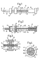
- FIG. 1
- is a lateral view of a stylet manipulation device according to the present invention;
- FIG. 2
- is a sectional view of the manipulation device along the line II-II in FIG. 1;
- FIG. 3
- is an enlarged sectional view of the circular area III in FIG. 2; and
- FIG. 4
- is a sectional view along the line IV-IV in FIG. 2.
- FIGS. 1 and 2 show a manipulation device, generally designated 10, for a stylet unit, for achieving a desired stiffening of an electrode cable (not shown) during its introduction into a body cavity, e.g. through a vein in the right atrium of the heart, and a desired positioning of the distal end of the electrode cable against the heart wall for fixation of the end there. The
manipulation device 10 is intended for manipulating astylet unit 12 of the kind containing an internal stylet 14 (shown most clearly in FIG. 3) and atubular sleeve 16 enclosing same, both thesleeve 16 and thestylet 14 intended for introduction inside the central channel of an electrode cable to stiffen the cable during its introduction. Thisstylet unit 12 is designed to bend the distal end of the electrode cable into e.g. a J shape when the cable reaches its final position. For this purpose, the internal stylet's 12 distal end is pre-curved in a known manner, but it is kept enclosed inside thetubular sleeve 16 during the electrode cable's introduction, thereby keeping the distal end section of thestylet unit 12 and, accordingly, the electrode cable essentially straight When the distal end of the electrode cable has been advanced e.g. into the right atrium of the heart, thetubular stylet sleeve 16 can be retracted, whereupon the pre-tensioning of the curved, exposed distal end section of thestylet 14 bends the flexible, distal end section of the electrode cable into the desired L or J shape. Themanipulation device 10 according to the invention is therefore designed to control the movement of thetubular sleeve 16 in relation to thestylet 14. Thedevice 10 comprises an elongatecylindrical housing 18 with aproximal end section 20 and adistal end section 22. A cavity in the form of a channel orhole 24, devised to admit thestylet sleeve 16, containing thestylet 14, with a tight fit, passes through the center of thehousing 18, as well as through a coil spring means 26, a free,proximal end section 14a of the stylet passing through aguide channel 27 in the spring means 26 (FIG. 4) to an attachment point F (FIG. 2) on theproximal end section 20 of thehousing 18. - The
housing 18 has an elongate,axial slot 28 which passes diametrically through the hole 24 (FIG. 4), thehole 24 in this slotted section of thehousing 18 then being limited by two opposing,semicylindrical walls operating slide 32 is arranged to move axially along thehousing 18 and has aring collar 34 which is connected to a hub section with two diametrically opposedradial pins 36 which pass through theslot 28, theproximal end 40 of thetubular sleeve 16 being affixed to said hub section. - In one appropriate embodiment, the coil spring means 26 is a pressure spring whose proximal end rests against or is mounted on a
proximal end section 42 affixed to theproximal end 20 of thehousing 18, whereas the distal end of the coil spring means presses against theproximal end section 40 of thetubular sleeve 16 and/or against the operating slide's 32hub section 26 which affixes this end section. Or the spring means 26 can consist of a draw spring whose ends are mounted on theend section 42 andtubular sleeve 16 orhub section 38. - An
end section 44, with an axial, distally projectingshaft journal 46 on which a known sleeve (not shown) can be mounted and which can be connected to a contact pin on the proximal end of the electrode cable to permit rotation of the cable during active fixation of the cable's distal end, is mounted on thedistal end 22 of thehousing 18. - The
manipulation device 10 according to the invention works in the following manner. Before the electrode cable is introduced into the body cavity, thestylet unit 12 is fully inserted into the electrode cable with thestylet 14 enclosed by thetubular sleeve 16, i.e. theoperating slide 32 is kept in a forward, distal end position in thehousing 18. When the distal end of thetubular sleeve 16 reaches the distal end of the electrode cable, the latter can be advanced into the body cavity, e.g. the right atrium of the heart. After it reaches the atrium, the distal end section of the electrode cable is bent into the desired L or J shape when the physician manually retracts theoperating slide 32 with his fingers, i.e. in the proximal direction, such that theslide 32 moves thetubular sleeve 16 and exposes the pre-curved distal end of thestylet 14 which accordingly bends the end of the electrode cable into the desired shape, depending on how much of the curved distal end of the stylet is exposed. When the spring means 26 consists of a draw spring, the spring means 26 tends to contract, thereby facilitating the operating slide's 32 movement in the proximal direction. When the spring means 26 is a pressure spring, this spring is compressed by the operating slide. In both instances, the primary task of the spring means 26 is to enclose, with a tight fit, or "brace" theproximal end section 14a of thestylet 14, thereby keeping thisfree end section 14a from being buckled by thestylet 14 because of friction between thestylet 14 and thesleeve 16. As a result of the shortening of the length of the spring means 26, the total length of the manipulatingdevice 10 can be kept relatively short. - When the distal end of the electrode cable reaches its final position, it can be actively affixed to the heart wall by manual rotation of a rotation sleeve (not shown) mounted on the shaft journal to which the electrode cable's proximal contact pin is affixed.
Claims (13)
- A device for manipulating a stylet unit (12) for positioning an electrode cable in a body cavity, said device (10) containing an elongate housing (18) with a proximal (20) and a distal (22) end section, an elongate axial cavity (24) in the housing (18) and an operating slide (32), axially moveable in relation to the housing, for connection to a proximal end section (40) of a tubular stylet sleeve (16) of the stylet unit (12), characterized in that the elongate cavity (24) is designed to enclose, with a tight fit, an elongate coil spring means (26) on the proximal side of the operating slide (32), said spring means (26) forming an inner, axial guide channel (27) to prevent a free, proximal end section (14a) of a stylet (14) of the stylet unit (12) from buckling when the operating slide (32) is retracting the proximal end section (40) of the stylet sleeve (16) over the free proximal end section (14a) of the stylet, while shortening the length of the spring means (26).
- A device according to claim 1, characterized in that the spring means (26) consists of a pressure spring with a proximal end and a distal end.
- A device according to claim 2, characterized in that the proximal end of the spring means (26) is affixed to the proximal end section (20) of the housing (18).
- A device according to claim 3, characterized in that the distal end of the spring means (26) is arranged to press against the proximal end section (40) of the stylet sleeve (16).
- A device according to claim 3, characterized in that the distal end of the spring means (26) is arranged to press against a hub section (38) of the operating slide (32).
- A device according to claim 2, characterized in that the spring means (26) consists of a draw spring with a proximal end attached to the proximal end section (20) of the housing (18) and with a distal end attached to the proximal end section (40) of the stylet sleeve (16) or the hub section (38) of the operating slide (32).
- A device according to any of claims 1-6, characterized in that the housing (18) has an axial, elongate slot (28) connecting the cavity (24) in the housing to the exterior of same.
- A device according to claim 7, characterized in that the cavity (24) is formed by a cylindrical hole in the proximal end section (20) of the housing (18) and by two opposed semicylindrical surfaces (30a, 30b) in the slot section of the housing (18).
- A device according to claim 7 or 8, characterized in that the operating slide (32) contains at least one trunnion (36), radially projecting from the proximal end section (40) of the stylet sleeve (16) which can move in the slot (28).
- A device according to claim 9, characterized in that the operating slide (32) comprises manipulation means (34), connected to the trunnion (36) which is movably journalled on the exterior of the housing (18).
- A device according to claim 10, characterized in that the manipulation means (34) is ring-shaped.
- A device of any of claims 1-11, characterized in that the distal end section (22) of the housing (18) has an axially projecting shaft journal (46) for a means for rotating the electrode cable.
- A device according to any of claims 1-12, characterized in that the proximal ends of the coil spring means (26) and stylet (14) are attached to fixed end section (42) on the proximal end section (20) of the housing (18).
Applications Claiming Priority (2)
| Application Number | Priority Date | Filing Date | Title |
|---|---|---|---|
| SE9503647 | 1995-10-18 | ||
| SE9503647A SE9503647D0 (en) | 1995-10-18 | 1995-10-18 | Control unit for a control wire unit |
Publications (2)
| Publication Number | Publication Date |
|---|---|
| EP0773036A1 EP0773036A1 (en) | 1997-05-14 |
| EP0773036B1 true EP0773036B1 (en) | 2003-01-02 |
Family
ID=20399868
Family Applications (1)
| Application Number | Title | Priority Date | Filing Date |
|---|---|---|---|
| EP96850169A Expired - Lifetime EP0773036B1 (en) | 1995-10-18 | 1996-10-11 | Device for manipulating a guide wire unit |
Country Status (5)
| Country | Link |
|---|---|
| US (1) | US5752915A (en) |
| EP (1) | EP0773036B1 (en) |
| JP (1) | JPH09122252A (en) |
| DE (1) | DE69625577T2 (en) |
| SE (1) | SE9503647D0 (en) |
Families Citing this family (20)
| Publication number | Priority date | Publication date | Assignee | Title |
|---|---|---|---|---|
| AUPO037496A0 (en) * | 1996-06-11 | 1996-07-04 | Wildon, Michael Peter | Epicardiac pacing lead |
| AU720147B2 (en) * | 1996-06-11 | 2000-05-25 | Michael Peter Wildon | Epicardiac pacing lead |
| SE9602998D0 (en) | 1996-08-16 | 1996-08-16 | Pacesetter Ab | Control unit for a control wire unit |
| US6178354B1 (en) | 1998-12-02 | 2001-01-23 | C. R. Bard, Inc. | Internal mechanism for displacing a slidable electrode |
| DE19930266A1 (en) * | 1999-06-25 | 2000-12-28 | Biotronik Mess & Therapieg | catheter |
| US6451016B1 (en) | 1999-07-12 | 2002-09-17 | C. R. Bard, Inc. | Displaceable ablation electrode |
| SE9903430D0 (en) * | 1999-09-22 | 1999-09-22 | Pacesetter Ab | A device for manipulating a styled unit |
| US6755794B2 (en) * | 2000-04-25 | 2004-06-29 | Synovis Life Technologies, Inc. | Adjustable stylet |
| US6776765B2 (en) * | 2001-08-21 | 2004-08-17 | Synovis Life Technologies, Inc. | Steerable stylet |
| US6944506B1 (en) | 2002-06-25 | 2005-09-13 | Pacesetter, Inc. | Stylet feature for resisting perforation of an implantable lead |
| US6973352B1 (en) | 2002-12-05 | 2005-12-06 | Pacesetter, Inc. | Steerable cardiac pacing and sensing catheter and guidewire for implanting leads |
| US20050177199A1 (en) * | 2004-02-09 | 2005-08-11 | Cardiac Pacemakers, Inc. | PSA cable and connector for quadripolar lead terminal |
| US7637916B2 (en) * | 2004-06-01 | 2009-12-29 | Medtronic, Inc. | Medical electrical lead implant tool |
| US20060089569A1 (en) * | 2004-10-26 | 2006-04-27 | Soukup Thomas M | Articulator with adjustable stiffness distal portion |
| US7753696B2 (en) * | 2005-05-12 | 2010-07-13 | Cardiac Pacemakers, Inc. | Lead terminal multi-tool |
| US7983764B2 (en) * | 2005-08-12 | 2011-07-19 | Cardiac Pacemakers, Inc. | Co-radial lead with extendable/retractable fixation mechanism and apparatus therefor |
| US7892186B2 (en) | 2005-12-09 | 2011-02-22 | Heraeus Materials S.A. | Handle and articulator system and method |
| US10992078B2 (en) | 2018-01-29 | 2021-04-27 | Bard Access Systems, Inc. | Connection system for establishing an electrical connection through a drape and methods thereof |
| EP3793464A4 (en) | 2018-05-18 | 2021-07-21 | Bard Access Systems, Inc. | Connection systems and methods thereof for establishing an electrical connection through a drape |
| WO2021021408A1 (en) | 2019-07-29 | 2021-02-04 | Bard Access Systems, Inc. | Connection systems and methods for establishing optical and electrical connections through a drape |
Family Cites Families (7)
| Publication number | Priority date | Publication date | Assignee | Title |
|---|---|---|---|---|
| US4136703A (en) * | 1978-03-09 | 1979-01-30 | Vitatron Medical B.V. | Atrial lead and method of inserting same |
| DE3150052C2 (en) * | 1981-12-17 | 1985-02-21 | Sterimed Gesellschaft für medizinischen Bedarf mbH, 6600 Saarbrücken | Catheter for catheterizing central veins |
| US4601599A (en) * | 1983-12-27 | 1986-07-22 | Katoh Kinzoku Kogyo Kabushiki Kaisha | Ball-point pen |
| US4935017A (en) * | 1988-04-29 | 1990-06-19 | C. R. Bard, Inc. | Variable shaped catheter system and method for catheterization |
| EP0450181B1 (en) | 1990-03-30 | 1995-05-17 | Pacesetter AB | Device for positioning an electrode |
| US5397321A (en) * | 1993-07-30 | 1995-03-14 | Ep Technologies, Inc. | Variable curve electrophysiology catheter |
| US5465733A (en) * | 1993-10-14 | 1995-11-14 | Hinohara; Tomoaki | Guide wire for catheters and method for its use |
-
1995
- 1995-10-18 SE SE9503647A patent/SE9503647D0/en unknown
-
1996
- 1996-10-11 EP EP96850169A patent/EP0773036B1/en not_active Expired - Lifetime
- 1996-10-11 DE DE69625577T patent/DE69625577T2/en not_active Expired - Fee Related
- 1996-10-15 US US08/732,815 patent/US5752915A/en not_active Expired - Fee Related
- 1996-10-18 JP JP8276583A patent/JPH09122252A/en active Pending
Also Published As
| Publication number | Publication date |
|---|---|
| EP0773036A1 (en) | 1997-05-14 |
| JPH09122252A (en) | 1997-05-13 |
| DE69625577D1 (en) | 2003-02-06 |
| US5752915A (en) | 1998-05-19 |
| DE69625577T2 (en) | 2003-07-10 |
| SE9503647D0 (en) | 1995-10-18 |
Similar Documents
| Publication | Publication Date | Title |
|---|---|---|
| EP0773036B1 (en) | Device for manipulating a guide wire unit | |
| EP1781363B1 (en) | A steerable catheter | |
| US4676249A (en) | Multi-mode guidewire | |
| US5944689A (en) | Variable curve electrophysiology catheter | |
| EP0619748B1 (en) | Steerable stylet and manipulative handle assembly | |
| EP1019140B1 (en) | Balloon catheterization | |
| US4586923A (en) | Curving tip catheter | |
| DE4201280C1 (en) | ||
| EP0778044B1 (en) | Guidewire unit | |
| US5833604A (en) | Variable stiffness electrophysiology catheter | |
| US5397321A (en) | Variable curve electrophysiology catheter | |
| EP1368085B1 (en) | Catheter for insertion of a stent | |
| EP1844739A1 (en) | Short handle for a long stent | |
| US9119609B2 (en) | Rotating cell collection device | |
| IE980241A1 (en) | Delivery catheter with split sheath | |
| CA2159824A1 (en) | Steerable stylet and manipulative handle assembly | |
| WO1996039998B1 (en) | Pull back sleeve system with compression resistant inner shaft | |
| CA2354367A1 (en) | A delivery apparatus for a self-expanding stent | |
| JPH119696A (en) | Catheter system | |
| EP1543785B1 (en) | A basket-like medical treating tool for removing occlusive material | |
| EP0713713A1 (en) | Balloon catheter | |
| WO1995003742A1 (en) | Bendable tip assemblies for catheters | |
| JPS6137931B2 (en) | ||
| EP0920344B1 (en) | Operating device for a stylet unit | |
| EP3298973B1 (en) | Endoscopic treatment instrument |
Legal Events
| Date | Code | Title | Description |
|---|---|---|---|
| PUAI | Public reference made under article 153(3) epc to a published international application that has entered the european phase |
Free format text: ORIGINAL CODE: 0009012 |
|
| AK | Designated contracting states |
Kind code of ref document: A1 Designated state(s): DE ES FR GB IT |
|
| 17P | Request for examination filed |
Effective date: 19971110 |
|
| RAP1 | Party data changed (applicant data changed or rights of an application transferred) |
Owner name: ST. JUDE MEDICAL AB |
|
| GRAG | Despatch of communication of intention to grant |
Free format text: ORIGINAL CODE: EPIDOS AGRA |
|
| 17Q | First examination report despatched |
Effective date: 20020304 |
|
| GRAG | Despatch of communication of intention to grant |
Free format text: ORIGINAL CODE: EPIDOS AGRA |
|
| GRAG | Despatch of communication of intention to grant |
Free format text: ORIGINAL CODE: EPIDOS AGRA |
|
| GRAG | Despatch of communication of intention to grant |
Free format text: ORIGINAL CODE: EPIDOS AGRA |
|
| GRAH | Despatch of communication of intention to grant a patent |
Free format text: ORIGINAL CODE: EPIDOS IGRA |
|
| GRAH | Despatch of communication of intention to grant a patent |
Free format text: ORIGINAL CODE: EPIDOS IGRA |
|
| GRAA | (expected) grant |
Free format text: ORIGINAL CODE: 0009210 |
|
| AK | Designated contracting states |
Kind code of ref document: B1 Designated state(s): DE ES FR GB IT |
|
| RTI1 | Title (correction) |
Free format text: DEVICE FOR MANIPULATING A GUIDE WIRE UNIT |
|
| REG | Reference to a national code |
Ref country code: GB Ref legal event code: FG4D Free format text: 20030102 |
|
| REF | Corresponds to: |
Ref document number: 69625577 Country of ref document: DE Date of ref document: 20030206 Kind code of ref document: P |
|
| PG25 | Lapsed in a contracting state [announced via postgrant information from national office to epo] |
Ref country code: ES Free format text: LAPSE BECAUSE OF FAILURE TO SUBMIT A TRANSLATION OF THE DESCRIPTION OR TO PAY THE FEE WITHIN THE PRESCRIBED TIME-LIMIT Effective date: 20030730 |
|
| ET | Fr: translation filed | ||
| PG25 | Lapsed in a contracting state [announced via postgrant information from national office to epo] |
Ref country code: GB Free format text: LAPSE BECAUSE OF NON-PAYMENT OF DUE FEES Effective date: 20031011 |
|
| PLBE | No opposition filed within time limit |
Free format text: ORIGINAL CODE: 0009261 |
|
| STAA | Information on the status of an ep patent application or granted ep patent |
Free format text: STATUS: NO OPPOSITION FILED WITHIN TIME LIMIT |
|
| 26N | No opposition filed |
Effective date: 20031003 |
|
| GBPC | Gb: european patent ceased through non-payment of renewal fee |
Effective date: 20031011 |
|
| PGFP | Annual fee paid to national office [announced via postgrant information from national office to epo] |
Ref country code: DE Payment date: 20041027 Year of fee payment: 9 |
|
| PGFP | Annual fee paid to national office [announced via postgrant information from national office to epo] |
Ref country code: FR Payment date: 20050930 Year of fee payment: 10 |
|
| PG25 | Lapsed in a contracting state [announced via postgrant information from national office to epo] |
Ref country code: DE Free format text: LAPSE BECAUSE OF NON-PAYMENT OF DUE FEES Effective date: 20060503 |
|
| PGFP | Annual fee paid to national office [announced via postgrant information from national office to epo] |
Ref country code: IT Payment date: 20061031 Year of fee payment: 11 |
|
| REG | Reference to a national code |
Ref country code: FR Ref legal event code: ST Effective date: 20070629 |
|
| PG25 | Lapsed in a contracting state [announced via postgrant information from national office to epo] |
Ref country code: FR Free format text: LAPSE BECAUSE OF NON-PAYMENT OF DUE FEES Effective date: 20061031 |
|
| PG25 | Lapsed in a contracting state [announced via postgrant information from national office to epo] |
Ref country code: IT Free format text: LAPSE BECAUSE OF NON-PAYMENT OF DUE FEES Effective date: 20071011 |